TEGO Glide 450(迪高450)技术资料
涂料的流动与流平(绝对经典)

涂料的流动与流平(绝对经典)一、前言涂膜的流平是涂料表观性能的体现,实际上流平性好坏涉及到涂料的许多方面,例如粘度、涂料的流变性、原材料匹配性、颜料分散工艺的设计、助剂的选择及应用技术、涂装工艺及涂装环境等诸方面因素。
可以说涉及到涂料生产及涂装的全过程,绝非单独依靠流平剂所能控制的。
以实际工作经验为基础,拟对涂料的流动与流平及其与流平剂的关系作如下介绍:流平剂在涂料的流动与流平中所发挥的作用。
流平剂种类不同作用机理和发挥的效果亦不同,即使流平剂的种类相同结构不同,使用效果亦不同。
所以应用流平剂时要根据涂料需要克服的问题和助剂的结构类别进行选择。
应用时要注意流平剂与其他助剂的匹配性及其负面作用和克服对策。
掌握了流平剂的应用对提高涂料产品质量水平会有一定帮助的,另外对流平剂的开发也是有益的。
二、影响涂料流动与流平的因素涂料流动成膜的力是外加的剪切力。
即外力作用于涂料使其铺展成膜。
流平的动力是表面张力即涂料自身收缩的力,这是在外力消失后,使涂膜表面达到光滑平整状态的主要作用力。
由此可以得出这样的结论:流动与流平两个定义之间没有什么太大的区别,涂料要达到光滑平整的表面需要具有良好的流动与流平特性。
2.1涂料流体性质对流动与流平的影响不管是流动还是流平都是涂料的运动形式,都要受到涂料粘度的影响。
涂料流体性质不同,粘度与剪切速率呈现出不同的关系,所以对流动和流平的影响程度也不一样。
如何利用涂料这一属性即达能到流动与流平的目的,又能克服涂料某些弊病是我们技术人员所追求的目标。
涂料大约有五种流体类型:牛顿流体、塑性流体、假塑性流体、膨涨流体、触变流体。
假塑性流体和触变流体是涂料最常用的两种流体结构。
它们对防沉、防浮色发花、防流挂、防止立面涂装时的波纹都是相当有益的。
但对流平和光泽会造成一定影响。
只要注意选择触变剂,合适地调节流挂极限膜厚度,仍有可能达到理想的涂膜流平效果。
由式1中可以看出极限膜厚度与屈伏值成正比,只要改变屈伏值就可以调整涂膜厚度。
450可配置控制器说明书

450 CONFIGURABLE CONTROLLERMain applications •Packaging machines •Packing machines• Labelers•Food processing lines andmachines •Laboratory machines and ovens •Electrical heaters for industrial heating Main features•Universal input configurable from the faceplate•Accuracy better than 0,2% f.s.at nominal condition•Control output: relay or logic with Heat or Cool function•1 alarm with configurable function •Self-tuning, Auto-tuning, Soft-start, Man/Auto function •Possibility to configure the unit byserial linePROFILEThe series 450 temperature controller, measuring 48x48mm (1/16 DIN), offers simplicity of use and high quality of con-trol.The input from temperature sensors is “universal” and configurable with type J, K, R, S, T, B, E, N thermocouples and with 3-wire Rt100 resistance thermome-ters.The user interface has a complete double display with green LEDs, 4 keys, and two red LEDs to signal active outputs.The Lexan® membrane on the front panel guarantees an IP65 protection level for these products.The controller outputs, freely configurable as control output and alarm output, are available in a 5A/250VAC relay version or in a logic signal version to drive solid state relays.The input signal read speed (120msec) and the tested PID control algorithm with selftuning and autotuning parameter functions guarantee accurate and stable control even for rapid and discontinuous heating systems.Series 450 models are factory-configured to satisfy most industrial heating applica-tions (input for probe J, hot PID setting, 10 second cycle time) and can always bemodified from keyboard and from PC witha few parameters grouped on intuitivemenus.A programming kit for PC is available,consisting of a cable and a user-friendlyprogram for Windows with Wizard pages,oscilloscope for process analysis, savingof parameter recipes, and ability to resetfactory parameters. A settable softwareprotection code (password-protected) letsyou limit access to internal parameters tovarious levels, up to total protection.TECHNICAL DATAI nputsAccuracy 0,2% f.s. ±1digit.Sampling time 120msec.TC - ThermocoupleJ(Fe-CuNi) 0...1000°C / 32...1832°FK(NiCr-Ni) 0...1300°C / 32...2372°FR(Pt13Rh-Pt) 0...1750°C / 32...3182°FS(Pt10Rh-Pt) 0...1750°C / 32...3182°FT(Cu-CuNi) -200...400°C / -328...752°FB(Pt30Rh-Pt6Rh) 44...1800°C / 111...3272°FE(NiCr-CuNi) -100...750°C / -148...1382°FN(NiCrSi-NiSi) 0...1300°C / 32...2372°FRTD 3-wiresPt100 -200...600°C / -328...1112°FO utputsOutputs fully configurable for control andsingle alarm function.RelayWith rating: 5A/250 Va.c., cos j=1(order code: R)Logic12V (6V min 20mA)(order code D)p Ower s upply(Standard) 100...240 V a.c. ±10% (Optional) 11...27 V a.c./d.c. ±10% 50/60Hz, max. 10VAA mbIent C OndItIOnWorking temperature range: 0...50°C Storage temperature range: -20...70°C Humidity: 20...85%Ur non condensing C OntrOlOn/Off, P, PD, PID either for heating or cooling, with parameters configurable from the faceplate.Cooling setpoint relative to heating setpoint.• Manual reset -999...999 digit• Power reset -100,0...100,0%• Cycle time 0...200sec• Soft-start 0,0...500,0 minFor each action:• Proportional band 0,0...999,9% f.s.• Integral time 0,0...99,99 min• Derivative time 0,0...99,99 min• Max power limit 0,0...100,0%A lArms• 1 alarm with setpoint settable at absolu-te, deviation, symmetrical deviation value compared to setpoint with direct or inver-se function.• The alarm point may be set anywhere within the configured scale.• LBA (Loop Break Alarm) function alarm • Alarm Hysteresis configurablew eIght210g complete versionFACEPLATE DESCRIPTIONL38888 450FCDE FCONNECTION DIAGRAMGEFRAN spa reserves the right to make any kind of design or functional modification at any moment without prior notice.GEFRAN spa via Sebina, 74 - 25050 Provaglio d’Iseo (BS)Tel. 03098881 - fax 0309839063 - Internet: DTS_450_10-2016_ENG。
Victrex_PEEK450CA30

VICTREX ® PEEK ™ high performance polymers ©Victrex plc Revision Mar 081VICTREX ® PEEK TM450CA30Product Description:High performance thermoplastic material, 30% carbon fibre reinforced P oly E ther E ther K etone (PEEK), semi crystalline, granules for injection moulding and extrusion, standard flow, FDA food contact compliant, colour black.Typical Application Areas:Applications for higher strength and stiffness in a static or dynamic system. Excellent wear resistance, low coefficient of friction, low coefficient of thermal expansion. Chemically resistant to aggressive environments.VICTREX ®PEEK ™high performance polymers ©Victrex plc 0620072Miscellaneous Density Crystalline ISO 1183 g cm -31.40 Shore D hardness23°C ISO 868 90 Water Absorption (3.2mm thick Tensile bar) 24 h, 23°C ISO 62-1% 0.04 (by immersion)Equilibrium, 23°C0.3Fire Smoke ToxicityFlammability RatingUL94 n/a V-0 @ 0.5 mmGlow Wire Test 2mm thickness IEC 60695-2-12ºC 960 Toxicity Index CO content NES 713n/a 0.05 CO 2 content 0.12Total gases0.17Recommended Processing ConditionsDrying Temperature / Time 150°C / 3h or 120°C / 5hTemperature settings 375 / 380 / 390 / 395°C (Nozzle)Hopper Temperature Not greater than 100°C Mould Temperature 180°C - 210°C (max 250°C) Mould Shrinkage Along Flow, 3 mm, 170°C mould, 0.0% Across flow, 3 mm, 170 °C mould, 0.5% Runner Die / nozzle >3mm, manifold >3.5mmGate>2mm or 0.5 x part thicknessDetailed data available on our website or upon requestWorld HeadquartersVictrex plc, Hillhouse International, Thornton Cleveleys, Lancashire FY5 4QD United Kingdom Tel: + (44) 1253 897700 Fax: + (44) 1253 897701 Email: victrexplc@VICTREX PLC BELIEVES THAT THE INFORMA TION CONT AINED IN THIS BROCHURE IS AN ACCURA TE DESCRIPTION OF THE TYPICAL CHARACTERISTICS AND/OR USES OF THE PRODUCT OR PRODUCTS, BUT IT IS THE CUSTOMER'S RESPONSIBILITY TO THOROUGHL Y TEST THE PRODUCT IN EACH SPECIFIC APPLICA TION TO DETERMINE ITS PERFORMANCE, EFFICACY AND SAFETY FOR EACH END-USE PRODUCT , DEVICE OR OTHER APPLICATION. SUGGESTIONS OF USES SHOULD NOT BE T AKEN AS INDUCEMENTS TO INFRINGE ANY P ARTICULAR P ATENT . THE INFORMA TION AND DA T A CONT AINED HEREIN ARE BASED ON INFORMA TION WE BELIEVE RELIABLE. MENTION OF A PRODUCT IN THIS DOCUMENT A TION IS NOT A GUARANTEE OF A V AILABILITY . VICTREX PLC RESERVES THE RIGHT TO MODIFY PRODUCTS, SPECIFICA TIONS AND/OR P ACKAGING AS P ART OF A CONTINUOUS PROGRAM OF PRODUCT DEVELOPMENT . VICTREX IS A REGISTERED TRADEMARK OF VICTREX MANUFACTURING LIMITED. VICOTE IS A REGISTERED TRADEMARK OF VICTREX PLC. PEEK™, APTIV™ AND PEEK-HT™ ARE TRADEMARKS OF VICTREX PLC.VICTREX PLC MAKES NO WARRANTIES, EXPRESS OR IMPLIED, INCLUDING , WITHOUT LIMIT A TION, A WARRANTY OF FITNESS FOR A P ARTICULAR PURPOSE OR OF INTELLECTUAL PROPERTY NON-INFRINGEMENT , INCLUDING , BUT NOT LIMITED TO P A TENT NON-INFRINGEMENT , WHICH ARE EXPRESSL Y DISCLAIMED, WHETHER EXPRESS OR IMPLIED, IN FACT OR BY LA W. FURTHER, VICTREX PLC MAKES NO WARRANTY TO YOUR CUSTOMERS OR AGENTS, AND HAS NOT AUTHORIZED ANYONE TO MAKE ANY REPRESENT A TION OR WARRANTY OTHER THAN AS PROVIDED ABOVE. VICTREX PLC SHALL IN NO EVENT BE LIABLE FOR ANY GENERAL, INDIRECT , SPECIAL, CONSEQUENTIAL, PUNITIVE, INCIDENT AL OR SIMILAR DAMAGES, INCLUDING WITHOUT LIMIT A TION, DAMAGES FOR HARM TO BUSINESS, LOST PROFITS OR LOST SA VINGS, EVEN IF VICTREX HAS BEEN ADVISED OF THE POSSIBILITY OF SUCH DAMAGES, REGARDLESS OF THE FORM OF ACTION.2。
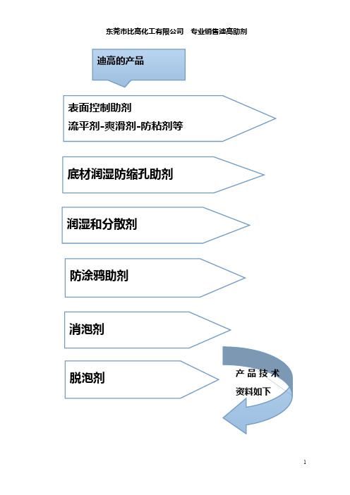
迪高产品应用
水
UV
溶
静
动
防
低
性
剂
态
态
缩
稳
体
型
表
表
孔
泡
系
面
面
张
张
力
力
●
●
●
●
●
●
●
●
●
●
●
●
●
●
●
●
●
●
●
●
●
●
●
●
●
●
●
●
●
●
●
●
●
●
●
●
●
●
●
●
●
●
●
●
●
●
●
●
●
●
●
●
●
●
●
●
●
推荐的助剂
TEGO Wet KL 245 适用于水性配方和溶剂型配方,重涂性佳。主要应用于:汽车涂料,塑胶漆, 工业涂料,木器漆,喷墨油墨等。
●●
TEGO®Foamex 805
●
●
●●
●●
●
TEGO®Foamex 8050 ●
●
●
●
TEGO®Foamex 810 ●
●●
●
●●
TEGO®Foamex 815N
●●
●
●●
●
TEGO®Foamex 822
●●●
●●
●●●
●
TEGO®Foamex 823
●●●
●●
●●●●
TEGO®Foamex 825
●
●
●
Lincoln Magnum PRO Curve 450 商品说明书

Operator’s ManualRegister your machine:/registerAuthorized Service and Distributor Locator: /locatorIM10416| Issue D a te Aug-17© Lincoln Global, Inc. All Rights Reserved.For use with Code Numbers:K3518-2, K3518-2-8-45, K3518-2-10-45Save for future referenceDate PurchasedCode: (ex: 10859)SECTION A:WARNINGSC ALIFORNIA PROPOSITION 65 WARNINGSWARNING: This product, when used for welding or cutting, produces fumes or gases which contain chemicals known to the State of California to cause birth defects and, in some cases, cancer. (California Health & Safety Code § 25249.5 et seq.)ARC WELDING CAN BE HAZARDOUS. PROTECTYOURSELF AND OTHERS FROM POSSIBLE SERIOUS INJURY OR DEATH. KEEP CHILDREN AWAY.PACEMAKER WEARERS SHOULD CONSULT WITH THEIR DOCTOR BEFORE OPERATING.Read and understand the following safety highlights. For additional safety information, it is strongly recommended that you purchase a copy of “Safety in Welding & Cutting - ANSI Standard Z49.1” from the American Welding Society, P.O. Box 351040, Miami, Florida 33135 or CSA Standard W117.2-1974. A Free copy of “Arc Welding Safety” booklet E205 is available from the Lincoln Electric Company, 22801 St. Clair Avenue, Cleveland, Ohio 44117-1199.BE SURE THAT ALL INSTALLATION, OPERATION,MAINTENANCE AND REPAIR PROCEDURES ARE PERFORMED ONLY BY QUALIFIED INDIVIDUALS.FOR ENGINE POWERED EQUIPMENT.1.a.Turn the engine off before troubleshootingand maintenance work unless themaintenance work requires it to be running.1.b.Operate engines in open, well-ventilated areas or vent the engineexhaust fumes outdoors. 1.c.Do not add the fuel near an open flame weldingarc or when the engine is running. Stop the engine and allow it to cool before refueling to with hot engine parts and igniting. Do not spill fuel when filling tank. If fuel is spilled, wipe it up and do not start engine until fumes have been eliminated.1.d. Keep all equipment safety guards, coversand devices in position and in good repair.Keep hands, hair, clothing and tools away from V-belts, gears, fans and all other moving parts when starting, operating or repairing equipment.1.e.In some cases it may be necessary to remove safety guards toperform required maintenance. Remove guards only when necessary and replace them when the maintenance requiring their removal is complete. Always use the greatest care when working near moving parts. 1.f. Do not put your hands near the engine fan. Do not attempt tooverride the governor or idler by pushing on the throttle control rods while the engine is running. 1.g.To prevent accidentally starting gasoline engines while turningthe engine or welding generator during maintenance work,disconnect the spark plug wires, distributor cap or magneto wire as appropriate. 1.h.To avoid scalding, do not remove the radiatorpressure cap when the engine is hot.ELECTRIC ANDMAGNETIC FIELDS MAY BE DANGEROUS2.a.Electric current flowing through any conductorcauses localized Electric and Magnetic Fields (EMF).Welding current creates EMF fields around welding cables and welding machines 2.b.EMF fields may interfere with some pacemakers, andwelders having a pacemaker should consult their physician before welding. 2.c.Exposure to EMF fields in welding may have other health effectswhich are now not known. 2.d.All welders should use the following procedures in order tominimize exposure to EMF fields from the welding circuit:2.d.1.Route the electrode and work cables together - Securethem with tape when possible.2.d.2.Never coil the electrode lead around your body.2.d.3.Do not place your body between the electrode and workcables. If the electrode cable is on your right side, the work cable should also be on your right side.2.d.4.Connect the work cable to the workpiece as close as pos-sible to the area being welded.2.d.5.Do not work next to welding power source.SAFETYTABLE OF CONTENTSTechnical Specifications.........................................................................................................................................A-1Installation ..................................................................................................................................................Section A Connector Kit Installation to Gun Cable......................................................................................................................A-2 K466-1 and K466-8 Installation (for Lincoln Feeders)................................................................................................A-3 K466-2 Installation (For Tweco Adapted Feeders)......................................................................................................A-3 K466-3 Installation (For Miller feeders; i.e. Millermatic 200, Cricket, S-32P, 54D...)...................................................A-3 K466-6 and K466-10 Installation (Wirematic and Lincoln 10 Series Feeders).............................................................A-3 Liner Installation and Trimming Instructions...............................................................................................................A-4 Rotating the Gun Tube...............................................................................................................................................A-4 Contact Tip and Gas Nozzle Installation......................................................................................................................A-4 Connection to Feeder.................................................................................................................................................A-4 Connection to Lincoln Feeders...................................................................................................................................A-4 Connection to Tweco Adapted Feeders......................................................................................................................A-4 Connection to Miller Feeders.....................................................................................................................................A-5 Connection To Lincoln Wirematic, Hobart Series 2000 Feeders, Or Sp100t Type Feeders..........................................A-5 Connection To Lincoln 10 Series Feeders..................................................................................................................A-5 Consumable Thread Sizes.........................................................................................................................................A-5Operation ..................................................................................................................................................Section B Electrodes and Equipment.........................................................................................................................................B-1 Making a Weld..........................................................................................................................................................B-1 Avoiding Wire Feeding Problems................................................................................................................................B-1Maintenance..................................................................................................................................................Section C Removal, Installation and Trimming Gun Liners.........................................................................................................C-1 Gun Tubes and Nozzles.............................................................................................................................................C-1 Gun Cables ............................................................................................................................................................C-1 Cable Repair ............................................................................................................................................................C-1 Troubleshooting............................................................................................................................................Section DPARTS CONTENT/DETAILS MAY BE CHANGED OR UPDATED WITHOUT NOTICE. FOR MOST CURRENT INSTRUCTION M ANUALS, GO TO .FIGURE 2FIGURE 3.125g)Slip the connector nut over the copper strands with the threadend out. Orient gun tube connector so machined flat is on theFIGURE 4 Pull the cut-off lead terminals off the trigger assembly andWire Feeder End Repair(REQUIRES 2 #S19492-1 TERMINALS)a)Remove the cable liner per 3.1.b)Remove the feeder end connector, molded gas plug (orbarbed fitting), cable handle nut, plastic tailpiece, andconnector cover (see Figure 6).NOTE:In order to remove the cable handle nut, the tail of the connector cover must be depressed and the cable handle nut rotated 1/4 turn counterclockwise as viewed from the feeder end.c)Remove incoming connector from cable by unscrewingconnector nut from incoming connector. If the cable innertube is difficult to remove from the connector assembly,carefully slit it lengthwise with a knife up to the brassconnector.d)Move the cable boot, cable handle, and strain relief towardthe middle of the cable past the damaged section.e)Cut off the damaged section of cable and strip off the outerjacket as shown in Figure 3. Be careful not to cut theinsulation on the control wires while stripping jacket. Stripthe red and white control leads 1/4" (6.4 mm) from the endand crimp a new S19492-1 terminal to each lead. Trim theinner tube to dimensions shown.NOTE:The cable contains four control leads. Any two control leads can be used, provided the two colors used are the same at both ends. The extra leads are spares that can be used if one of the other leads breaks.f)Check that the cable boot, cable handle and strain relief areon the cable. Slip the connector nut over the copper strands with the threaded end out. Assemble incoming connector tocable by forcing the steel tube of the connector into the inside diameter of the cable inner tube until the copper strands are butted against the incoming connector shoulder. Keeping the copper strands against the shoulder, pull the connector nutover the copper strands, engage the incoming connectorthreads, and tighten in place. Refer to Figure 4.NOTE:For best results, insert a .250" (6.4mm) diameter rod through the connector and into core of cable approximately11.00" (280 mm) when pushing the connector tube into thecable core tube. To tighten, hold the connector in place while turning the nut, then remove the rod from the core. Thisprocedure assures the inner core does not kink whileassembling or tightening.Position the plastic strain relief such that the tapered end is7.10" (180 mm) from the incoming connector (see Figure 6).Lock into place with steel housing.g)Position cable boot and cable handle on cable and assemblereplacement control wire terminals in place on the cablehandle. Insert connector cover in place. Install tailpiece and fasten to cable handle with cable handle nut. Refer to Figure 6.h)Replace the molded gas plug (or barbed fitting) and feederend connector.i)Install and trim liner per Section 1.2.FIGURE 6If for any reason you do not understand the test procedures or are unable to perform the tests/repairs safely, contact yourIf for any reason you do not understand the test procedures or are unable to perform the tests/repairs safely, contact yourATENÇÃOJapaneseChineseKoreanArabicREAD AND UNDERSTAND THE MANUFACTURER’S INSTRUCTION FOR THIS EQUIPMENT AND THE CONSUMABLES TO BE USED AND FOLLOW YOUR EMPLOYER’S SAFETY PRACTICES.SE RECOMIENDA LEER Y ENTENDER LAS INSTRUCCIONES DEL FABRICANTE PARA EL USO DE ESTE EQUIPO Y LOS CONSUMIBLES QUE VA A UTILIZAR, SIGA LAS MEDIDAS DE SEGURIDAD DE SU SUPERVISOR.LISEZ ET COMPRENEZ LES INSTRUCTIONS DU FABRICANT EN CE QUI REGARDE CET EQUIPMENT ET LES PRODUITS A ETRE EMPLOYES ET SUIVEZ LES PROCEDURES DE SECURITE DE VOTRE EMPLOYEUR.LESEN SIE UND BEFOLGEN SIE DIE BETRIEBSANLEITUNG DER ANLAGE UND DEN ELEKTRODENEINSATZ DES HER-STELLERS. DIE UNFALLVERHÜTUNGSVORSCHRIFTEN DES ARBEITGEBERS SIND EBENFALLS ZU BEACHTEN.ATENÇÃOJapaneseChineseKoreanArabicLEIA E COMPREENDA AS INSTRUÇÕES DO FABRICANTE PARA ESTE EQUIPAMENTO E AS PARTES DE USO, E SIGA AS PRÁTICAS DE SEGURANÇA DO EMPREGADOR.customer assistance policYThe business of The Lincoln Electric Company is manufacturing and selling high quality welding equipment, consumables, and cutting equipment. Our challenge is to meet the needs of our customers and to exceed their expectations. On occasion, purchasers may ask Lincoln Electric for advice or information about their use of our products. We respond to our customers based on the best information in our possession at that time. Lincoln Electric is not in a position to warrant or guarantee such advice, and assumes no liability, with respect to such information or advice. We expressly disclaim any warranty of any kind, including any warranty of fitness for any customer’s particular purpose, with respect to such information or advice. As a matter of practical consideration, we also cannot assume any respon-sibility for updating or correcting any such information or advice once it has been given, nor does the provision of information or advice create, expand or alter any warranty with respect to the sale of our products.Lincoln Electric is a responsive manufacturer, but the selection and use of specific products sold by Lincoln Electric is solely within the control of, and remains the sole responsibility of the customer. Many variables beyond the control of Lincoln Electric affect the results obtained in applying these types of fabrication methods and service requirements.Subject to Change – This information is accurate to the best of our knowledge at the time of printing. Please refer to for any updated information.。
PHE450中文资料

234In accordance with IEC E12 series.±5% standard. Other tolerances on request –55° C to +105° C +85° CThe rated voltage is decreased with 1.3% / ° C between +85° C and +105° C 55/105/56The 100 % factory test is carried out at 1.6 x U R VDC Measured at 23° C, 100 VDC 60s for U R < 500 VDC and at 500 VDC for U R ≥ 500 VDC Between terminals:C ≤ 0.33 µF: ≥ 100 000 M ΩC > 0.33 µF: ≥ 30 000 sBetween terminals and case:≥ 100 000 M ΩMaximum values at 23°CC ≤ 0.1 µF 0.1 µF < C ≤ 1.0 µFC > 1.0 µF 1 kHz 0.03 %0.03 %0.03 %10 kHz 0.04 %0.06 %–100 kHz 0.15 %––Approximately 6 nH/cm for the total length of capacitor winding and the leads.The capacitors can withstand an unlimited number of pulses with a dU/dt according to the article table. For peak to peak voltages lower than the rated voltage (U PP < U R ), the specified dU/dt can be multiplied by U R /U PP .PHE450• Double metallized film pulse capacitor, polypropylene dielectric • According to IEC 60384-17 Grade 1.1• Small sizes• Replacing PHE427, PHE428TYPICAL APPLICATIONSCONSTRUCTIONTECHNICAL DATAHigh frequency applications with high current stress, such as deflection circuits in TV-sets, protection circuits in SMPS and in electronic ballasts.Polypropylene dielectric with double metallized polyester film as electrodes.Encapsulation in self-extinguishing material meeting the requirements of UL 94V-0.Rated voltage U R , VDC Rated voltage U R , VAC Capacitance range Capacitance valuesCapacitance tolerance Categorytemperature range Rated temperature Voltage derating Climatic category T est voltagebetween terminals Insulation resistanceDissipation factor tan δInductance Pulse rise timeENVIRONMENTAL TEST DATAAccording to IEC 60384-17, Grade 1.1 and Quality tests and requirements for PulseCapacitors in the Evox Rifa Film Capacitors catalogue.p d std I max I b 7.5±0.40.65-130± 0.410.0±0.40.65-130± 0.415.0±0.40.86-130± 0.422.5±0.40.86-130± 0.427.5±0.40.86-130± 0.437.5±0.51.06-130± 0.7Three different winding constructions are used, depending on voltage and lead spacing. They are specified in the article table.2 section construction3 section construction235PHE450µF F FµF FPHE450236PHE450237PHE450238PHE450239PHE450240PHE450241PHE450242PHE450243PHE450244PHE450245。
迪高主要助剂介绍

Tego Rad 2100
自由基交联型流动促进剂,高相容性、可交联性佳、良好的再涂性和覆印性、可轻微增加滑爽性、防缩孔,特别适用于辐射固化体系。
Tego Rad 2200N
高相容性自由基交联型增滑及流动助剂,可交联性、高效、防缩孔,在面漆配方中可提高表面滑度和抗擦伤性,同时可提高基材润湿和流平性。特别适用于辐射固化体系,亦可用于水性紫外光固化体系。
用于辐射固化油墨和涂料体系的高性能润湿分散剂,特别适用于有机颜料和碳黑,展色性能优异、着色力强,良好的降粘效果,不含溶剂和APE。
Tego Dispers681UV
用于辐射固化油墨和涂料体系的高性能润湿分散剂,特别适用于有机颜料和碳黑,展色性能优异、着色力强,良好的降粘效果,不含溶剂和APE。
Tego Dispers 700
Tego Dispers 750W
适用于水性印刷油墨及涂料的通用润湿分散剂,特别推荐用于不含基料的色浆生产。对无机、有机颜料和碳黑都有极好的稳定作用,非常好的展色性及突出的色浆稳定性。储存稳定性佳、抗水性佳,不含溶剂和乙氧基壬基酚。
Tego Dispers 752W
用于水性体系润湿和分散剂,特别推荐用于透明氧化铁和透明钛白粉。优异的展色性及储存稳定性佳、抗水性佳,不含乙氧基壬基酚。
特别适用于溶剂型和无溶剂型(双组份)体系、脱泡破泡性佳、热稳定性好、重涂性好。
Tego Glide 432
特别适用于辐射固化体系、突出的基材润湿性、提高抗擦伤性、高效、不稳泡。
Tego Glide 435
流动及平滑性佳、基材润湿性佳、改善抗擦伤性、高效、低稳泡、适用于水性、辐射固化和溶剂型体系,特别适用于辐射固化体系。
高效的非有机硅类脱泡剂,特别推荐用于双组份聚氨酯和酸固化体系,以及基于硝基纤维素及其混合物的涂料,可用于底漆及面漆,适合高光泽配方,推荐用于刷涂、喷涂及滚涂。
GD-S450说明书正文(白色纸打印)

组成:包括印刷头(刮刀升降行程自动调节装置、刮刀片安装部分)、刮刀横梁及刮刀驱动部分(步进马达、联轴器)等。
功能:悬浮式能平衡自重的自适应刮刀,刮刀Y方向驱动使用随动结构,双滑块线性导轨,印刷平稳,动作敏捷,独立直联式步进马达控制,内置精确压力控制系统,能精确的测定刮刀原始压力值,无需顾及刮刀片类型,长度,重量或者厚度的变化.可编程实现印刷工艺灵活多变。
3.1开机前检查……………………………………………………………13
3.2开始生产前准备………………………………………………………13
3.2.1模板的准备………………………………………………………13
3.2.2锡膏准备………………………………………………………14
3.2.3PCB定位调试…………………………………………………14
第二章设备安装与调试……………………………………………………9
2.1开箱……………………………………………………………………9
2.2操作环境………………………………………………………………10
2.3设备安置及高度调整…………………………………………………10
2.4电源气源………………………………………………………………10
1.4.6电控系统
组成:
Windows XP操作系统,集成电路,智能化的先进软件控制。
特点:安全,维修方便,极大地方便了用户的使用。
1.5工作原理
由以上各部组成的全自动视觉印刷机在印刷焊膏时,锡膏受刮刀的推力产生滚动的前进,所受到的推力可分解为水平方向的分力和垂直方向的分力。当运行至模板窗口附近,垂直方向的分力使粘度已降低的焊膏顺利地通过窗口印刷到PCB焊盘上,当平台下降后便留下精确的焊膏图形。
- 1、下载文档前请自行甄别文档内容的完整性,平台不提供额外的编辑、内容补充、找答案等附加服务。
- 2、"仅部分预览"的文档,不可在线预览部分如存在完整性等问题,可反馈申请退款(可完整预览的文档不适用该条件!)。
- 3、如文档侵犯您的权益,请联系客服反馈,我们会尽快为您处理(人工客服工作时间:9:00-18:30)。
TEGO Glide 450(迪高450)
平滑和流动助剂
特性
●可普遍用于水性,辐射固化和溶剂型配方中
●高效能
●高相容性(发雾的风险减至最低)
●良好的重涂性
●改善耐刮擦性
●对层间附着力的影响极小
●给皮草面漆提供光滑的手感
电话135.370.070.10 李小姐 QQ197.973.11.18
应用实例
●木器和家具涂料推荐
用量:0.05~0.5%
●水性和溶剂型工业涂料推荐
用量:0.05~0.3%
●汽车漆推荐
用量:0.03~0.2%
●辐射固化印刷油墨和罩印光油的环氧体系(阳离子固化) 推荐
用量:0.05~1.0%
●基于聚氨脂,丙烯酸树脂,硝基和干酪素体系的皮革面漆推荐
用量:0.1~1.0%
(以供货形式对总配方计)
工艺说明
●预稀释或按供应形直接添加于涂料中均可。
●用推荐的溶剂预稀释会便于加入和混合。
技术数据
●供货形式透明液体
●成份聚醚硅氧烷共聚物
●活性物含量约100%
●粘度,25℃约 250 mPa s
包装储存
●25kg/塑料桶
●200kg/铁桶
●未开封的原包装中12个月。