SIC433-02光敏传感器规格书(可天士)
天科合达2英寸SiC晶片产品标准

Cumulative area ≤2%
5 scratches to 1×wafer diameter cumulative length 3 allowed, ≤0.5 mm each
Cumulative area ≤5%
5 scratches to 1×wafer diameter cumulative length 5 allowed, ≤1 mm each
6H-N/6H-SI/4H-N/4H-SI
≤1 cm-2
≤5 cm-2
≤15 cm-2
On axis : <0001>±0.5° for ≤50 cm-2
电阻率
Resistivity
4H-N 6H-N 4/6H-SI
0.015~0.028 Ω·cm 0.02~0.1 Ω•cm ≥1E5 Ω·cm
主定位边方向 Primary Flat
表面污染物(强光灯观测) Contamination by high intensity light
None
Notes:
* Defects limits apply to entire wafer surface except for the edge exclusion area.
# Defects shall be existed in the edge area, only defect beyond of the prescribed scope could be considered as reject cause.
厚度
Thickness
330 μm±25μm
晶片方向 微管密度
Wafer Orientation Micropipe Density
施克SICK G2S 迷你型光电传感器型号介绍
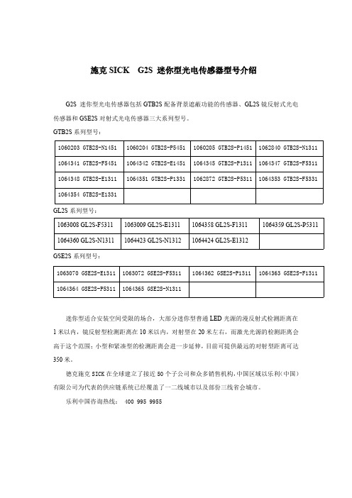
施克SICK G2S迷你型光电传感器型号介绍G2S迷你型光电传感器包括GTB2S配备背景遮蔽功能的传感器、GL2S镜反射式光电传感器和GSE2S对射式光电传感器三大系列型号。
GTB2S系列型号:1060203GTB2S-N14511060204GTB2S-P54511060205GTB2S-P14511062840GTB2S-N1311 1064341GTB2S-F54511064342GTB2S-E14511064345GTB2S-P131********GTB2S-F5311 1064348GTB2S-E131********GTB2S-P133********GTB2S-P53111064353GTB2S-F5331 1064354GTB2S-E1331GL2S系列型号:1063008GL2S-F53111063009GL2S-E131********GL2S-F131********GL2S-P5311 1064360GL2S-N131********GL2S-N131********GL2S-E1312GSE2S系列型号:1063070GSE2S-E131********GSE2S-F53111064362GSE2S-P131********GSE2S-F1311 1064364GSE2S-P53111064365GSE2S-N1311迷你型适合安装空间受限的场合,大部分迷你型普通LED光源的漫反射式检测距离在1米以内,镜反射型检测距离在10米以内,对射型在20米左右,而激光光源的检测距离会高于这个范围;小型和紧凑型的检测距离会进一步延伸,目前可提供最远的对射型距离可达350米。
德克施克SICK在全球建立了接近50个子公司和众多销售机构,中国区域以乐利(中国)有限公司为代表的供应链系统已经覆盖了一二线城市以及部份三线省会城市。
乐利中国咨询热线:4009959955。
光敏电阻型号及参数

光敏电阻型号及参数光敏电阻,也被称为光敏电阻器或光电导电阻器,是一种用于测量光强度的电阻器件。
它的电阻值会随着周围光照强度的变化而变化。
下面是几个常见的光敏电阻型号及其参数:1.GL5528-最大光敏电阻值:20MΩ- 光敏特性:响应波长400-700nm- 外观:圆形,直径为5mm-工作温度范围:-30°C至+70°C-主要应用:室内光控制设备、室外太阳能照明系统、安全系统等。
2.LDR5528-最大光敏电阻值:20MΩ- 光敏特性:响应波长540nm- 外观:圆形,直径为5mm-工作温度范围:-30°C至+70°C-主要应用:自动照明系统、相机调焦控制、电子血压计等。
3.VT90N2-最大光敏电阻值:5MΩ- 光敏特性:响应波长400-1000nm- 外观:方形,尺寸为5.8mm x 4.8mm x 2.0mm-工作温度范围:-30°C至+70°C-主要应用:光电开关、光电传感器、荧光检测等。
4.PRM7510-最大光敏电阻值:100KΩ- 光敏特性:响应波长380-1000nm- 外观:圆形,直径为6mm-工作温度范围:-20°C至+80°C-主要应用:计时器、自动控制系统、光电探测器等。
5.CDS-5-最大光敏电阻值:1MΩ- 光敏特性:响应波长400-700nm- 外观:圆形,直径为5mm-工作温度范围:-30°C至+70°C-主要应用:室内照明控制、安防系统、电子游戏机等。
以上只是部分常见的光敏电阻型号和参数,市场上还有很多其他型号的光敏电阻可供选择。
在选择光敏电阻时,需要根据具体应用需求来选择合适的型号,如测量范围、响应波长、工作温度范围等。
此外,还需根据电路设计的要求考虑光敏电阻的尺寸、灵敏度、稳定性等因素。
Ramco Innovations Z2系列光感传感器说明书

Cost effective and Eco-FriendlyLow price achieved by equipping our unique Opto-ASIC Employs a newly developed 4 element red LED light source Ultra-low current consumptionEasy-to-see indicators and operating panelSelection tableFor the connector type, please purchase an optional JCN series connector cable.Options/AccessoriesReflectorReflective sheetStandard (included withretro-reflective type)V-6160.9 × 50.9 mm Sensing distance:0.01 to 4.4 mSmall type V-4242 × 35 mm Sensing distance:0.01 to 2.7 mVertical type P45A54 × 12.4 mm Sensing distance:0.01 to 1.5 mSide mount P2532 × 14 mm Sensing distance:0.01 to 2 mUltra-small V-3043 × 23 mm Sensing distance:0.01 to 2.5 mDiamond grade sheet 100 × 100 mm Sensing distance:0.1 to 1.1 mProtective mounting bracketAnti-interference filter Slit mask for through-beam typeConnector cables Durable 2 mm thick stainless steel typeLK seriesBL-100-POLF For through-beam type (4 pieces)BL-W100Slit width 0.5 mm, 1 mm,2 mm (2 of each)StraightJCN-SCable length: 2 m JCN-5S Cable length: 5 m JCN-10S Cable length: 10 m LK-S01LK-S02L-shaped JCN-LCable length: 2 mJCN-5LCable length: 5 mJCN-10LCable length: 10 mRelated productsSensor head for amplifier separate typeZ3R-QP .404BGS type BGS-ZP .326Laser typeZ-LP .272Detection of deviation from conveyor belts Detection of glossy pouches Detection of paper passage168Ramco National - Optex FA Sensors Got Questions? 1-800-280-6933Low cost type Z2 seriesAchieved by our unique Opto-ASICRealized unprecedented price reductionWe’ve succeeded in lowering costs through in-house development of the chip-on-board Opto-ASIC, in which both a switching circuit and light receiving element have been integrated.Employs a newly developed high-brightness 4 element LEDLongest sensing distance in the class!Equipped with a newly developed 4 element red LED light source. In addition to minimizing the decreases in emitted light that occur over time, it features a through-beam type sensor with a longest-in-class 25 m sensing distance! Not only is detection over long distances possible, but it is also tolerant against dust and fine particles.Eco-friendly Ultra-low current consumptionPower consumption reduced by 35% *, contributing to the eco-friendliness of all devices and machinery.*When compared with our conventional retro-reflective typeMirrored cover of indicator partSilk-printed operating panelEnhanced operabilityEasy-to-see indicators and operating panelThe indicator part is equipped with a cover featuring an inner-surface reflecting structure. The cover surface does not diffuse light, but instead improves visibility by reflecting light in multiple directions internally.Also, silk printing has been used for the operating panel. This is a user-friendly design that enables labelling to be easily seen even in dark areas.Retro-reflective typeSensing distance: 0.01 to 4.4 mDiffuse-reflective typeSensing distance: 0 to 1 mLED chipsLow deterioration 4 element red LED.The spot light is also highly visible.Through-beam typeSensing distance: 25 mLow cost type Z2 seriesSpecifications*1. When reflector V-61 is used*2. Using a 100 × 100 mm white sheet of paper.*3. Mounting bracket BEF-W100-A is included with the connector type.Low cost type Z2 seriesOutput circuit diagramNPN output typeThrough-beam type emitterPNP output type(Pin configuration)Sensor side Connector cable sideConnecting1 to 4 are connector pin No.NotesW hen using a switching regulator for the power supply, be sure to ground the frame ground terminal. B ecause wiring sensor wires with high-voltage wires or power supply wires can result in malfunctions due to noise, which can cause damage, make sure to wire separately. A void using the transient state while the power is on (approx. 100 ms). T he connector direction is fixed as the drawing below when you use L-shaped connector cable. Be aware that rotation is not possible.1 10 to 30 VDC2 —3 0 V4 Control output0 V10 to 30 VDC0 V10 to 30 VDCConnector type0 V10 to 30 VDCLow cost type Z2 seriesDimensionsSensor(Unit: mm)Mounting bracketCable typeBEF-W100-B (included with cable type)Connector typeBEF-W100-A (included with connector type)Through-beam type receiver/retro/diffuseThrough-beam type emitterselection switch2-M3 (tightening torque:Low cost type Z2 series Reflector(Unit: mm)V-61: Standard type reflector (included with retro-reflective type) P45A: Vertical type reflector (optional)V-30: Ultra-small reflector (optional) V-42: Small reflector (optional)P25: Side mount reflector (optional)Low cost type Z2 seriesDimensionsProtective mounting bracket(Unit: mm) LK-S01LK-S0226Low cost type Z2 seriesConnector cable (optional)Slit mask(Unit: mm)JCN-S, JCN-5S, JCN-10SBL-W100: Slit mask (optional)JCN-L, JCN-5L, JCN-10Lø9.8ø4.7 4-wire × 0.325 mm 2 PVC (vinyl)18.8ø5 4-wire × 0.25 mm 2ø9.860Low cost type Z2 seriesTypical characteristic dataZ2T-2000When slit mask is attached Z2T-2000Excess gain11010010203040Operation level③E x c e s s g a i n ④③O p e r a t i n g p o i n t Y (m m )④③D i s t a n c e X (m )④③D i s t a n c e Y (m )④③Sensing distance (m)④③Sensing distance X (m)④③Operating angle (°)④③Sensing distance X (m)④③Sensing distance (m)④③Sensing distance X (m)④③Angle (°)④③Angle (°)④③E x c e s s g a i n ④③O p e r a t i n g p o i n t Y (m m )④③D i s t a n c e X (m )④③D i s t a n c e X (m )④③Angle (°)④③Sensing distance X (m)④③D i s t a n c e X (m )④③D i s t a n c e Y (m )④Low cost type Z2 seriesZ2D-80Z2R-400Excess gain1White paper:Re ection rate 90%Gray paper:Re ection rate 18%Black paper:Re ection rate 6%1005001000Operation level ③D i s t a n c e Y (m m )④100③E x c e s s g a i n ④③D i s t a n c e Y (m )④③O p t i c a l p l a n e ④③Sensing distance (mm)④③Sensing distance X (mm)④③Sensing distance (mm)④③Sensing distance X (mm)④③E x c e s s g a i n ④③O p e r a t i n g p o i n t Y (m m )④③D i s t a nc e Y (m m)④③S e n s i n g d i s t a n c e X (m ) ④③S e n s i n g d i s t a n c e X (m ) ④③Sensing distance (m)④③Sensing distance X (m)④③Angle (°)④③Angle (°)④③S e n s i n g d i s t a n c e X (m ) ④③Angle (°)④③Sensing distance X (m)④New industry standard sensorLongest sensing distance in class at 25 m*Significantly reduced dead zoneIndicators visible from any angle*Red LED type, with through-beam typeSelection tableA mounting bracket is not included. If necessary, please purchase separately.A reflector is not included with the retro-reflective type. Please purchase an optional reflector separately.For the connector type, please purchase an optional connector cable separately.For the sensor head for amplifier separate type, please refer to P.404.Options/AccessoriesReflector Connector cablesReflective sheetStandardV-6160.9 × 50.9 mmSensing distance:Z3R-4000.01 to 4 mSmall typeV-4242 × 35 mmSensing distance:Z3R-4000.01 to 2.4 mUltra-smallV-3043 × 23 mmSensing distance:Z3R-4000.01 to 2.2 mVertical typeP45A54 × 12.4 mmSensing distance:Z3R-4000.01 to 1.4 mStraightJCN-SCable length: 2 mJCN-5SCable length: 5 mJCN-10SCable length: 10 mJCN-LCable length: 2 mJCN-5LCable length: 5 mJCN-10LCable length: 10 mL-shapedDiamond grade sheetSensing distance:Z3R-4000.1 to 1 m100 × 100 mm(adhesive type)Side mountP2532 × 14 mmSensing distance:Z3R-4000.01 to 1.6 mRelatedproductsSensor head for amplifierseparate typeZ3R-QP.404BGS typeBGS-ZP.326Laser typeZ-LP.272148Mounting bracket Protective mounting bracketLK series Slit mask Stainless steel slit mask Anti-interference filterWorld-renowned Z series basic photoelectric sensors continue to evolve.Total volume of Z series photoelectric sensors sold around the world exceeds 3 million units. The FASTUS Z3 series built-in amplifier photoelectric sensors with improved detection performance is the successor of the easy-to-use Z series.This series takes the functionality, practicality and cost performance required of general purpose photoelectric sensors to the next level.Sensing distanceLongest in class*Red LED type, with through-beam typeFeatures an industry standard mounting pitch of 25.4 mmIndicators visible from any angle25 mFor cable typeFloor-mountedBEF-W100-BFor connector type Back-mounted BEF-W100-A Cannot be used with connector cable JCN- L.Slit mask for through-beamtype (adhesive type)BL-W100Shipped with two of each slitwidth (0.5 mm, 1 mm, 2 mm).Stainless steel slit mask forthrough-beam typeBL-100-M1-10pcsBL-100-M0510 pieces of slit masks are shippedfor M1 with a slit width of 1 mm,and 1 piece of slit mask is shippedfor M05 with a slit width of 0.5 mm.For through-beamtype (4 pieces)BL-100-POLF LK-S01LK-S02Ultra-durable 2 mm thick typeRust-resistant stainless steelS ensor is firmly secured using M3Hex socket head cap screwsT he bracket is also firmly securedusing M6 screwsFeaturesHigh power LED provides stable detectionThe Z3 series through-beam type sensor has a 25 m sensing distance, the longest in its class.The margin for the receiving light quantity has been increased significantly, helping the sensor overcome interference from dust or other fine particles.Significantly reduced dead zoneThe diffuse-reflective type features an optimized optical receiver structure that successfully minimizes the dead zone in front of the lens.This makes it easier to detect workpieces with a low reflectivity that pass close to the sensor, even on lines that convey workpiecesof varying heights.Z3T-2500□Sensing distance:Sensing distanceTwi c eor moreSigni cantly increased excess gainSensing distance (m)PlusEasy optical axis adjustment thanks to a large spot size with good visibility 4 element LED helps reduce emitting power degradation during long-term useThrough-beam type emitterClose-range dead zone (typical value)*2. Using a 200 × 200 mm white sheet of paper. *3. Using a 100 × 100 mm white sheet of paper. *4. Using a 300 × 300 mm white sheet of paper.Specifications are subject to change without prior notice for product improvement purposes.Output circuit diagramNPN output typePNP output typeThrough-beam type emitterConnector typeConnecting1 to 4 are connector pin No.NotesW hen using a switching regulator for the power supply, be sure to ground the frame ground terminal.B ecause wiring sensor wires with high-voltage wires or power supply wires can result in malfunctions due to noise, which can cause damage, make sure to wire separately. Avoid using the transient state while the power is on (approx. 100 ms). T he connector direction is fixed as the drawing below when you use L-shaped connector cable. Be aware that rotation is not possible.0 V10 to 30 VDC0 V10 to 30 VDC0 V10 to 30 VDC(Pin configuration)Sensor sideConnector cable side1 10 to 30 VDC2 —3 0 V4 Control outputDimensionsSensorCable type Connector type(Unit: mm)Through-beamMounting bracketBEF-W100-BBEF-W100-ADimensionsReflectorV-61: Standard type reflectorProtective mounting bracketLK-S01 LK-S02(Unit: mm)V-30: Ultra-small reflectorP25: Side mount reflector26V-42: Small reflector P45A: Vertical type reflectorConnector cableJCN-S, JCN-5S, JCN-10SJCN-L, JCN-5L, JCN-10LSlit maskBL-W100BL-100-M1 BL-100-M05ø5 4-wire × 0.25 mm 2ø9.8ø9.8ø4.7 4-wire × 0.325 mm 218.8(Unit: mm)60Section-ATypical characteristic dataZ3T-2500When slit mask is attached Z3T-2500Z3R-400③D i s t a n c e Y (m )④③Sensing distance X (m)④③Sensing distance (m)④③Angle (°)④Excess gain110100100005101520253035③Sensing distance X (m)④③E x c e s s g a i n ④③O p e r a t i n g p o i n t Y (m m )④③D i s t a n c e X (m )④Operation level③Sensing distance (m)④③Sensing distance X (m)④③Sensing distance X (m)④③Angle (°)④③D i s t a n c e X (m )④③E x c e s s g a i n ④③O p e r a t i n g p o i n t Y (m m )④③D i s t a n c e Y (m )④③Sensing distance (m)④③Sensing distance X (m)④③Sensing distance X (m)④③Angle (°)④③E x c e s s g a i n ④③O p e r a t i n g p o i n t Y (m m )④③D i s t a n c e X (m )④③D i s t a n c e Y (m m )④③Sensing distance (m)④③Sensing distance X (m)④③Sensing distance X (m)④③Angle (°)④③E x c e s s g a i n ④③O p e r a t i n g p o i n t Y (m m )④③D i s t a n c e X (m )④③D i s t a n c e Y (m m )④Z3D-100Z3D-L09Z3D-W20③Sensing distance X (mm)④③E x c e s s g a i n ④③D i s t a n c e Y (m m )④③Sensing distance X (mm)④③O p t i c a l p l a n e ④③Distance (mm)④③O p e r a t i n g p o i n t Y (m m )④③Sensing distance (mm)④③Sensing distance X (mm)④③Sensing distance (mm)④③E x c e s s g a i n ④③D i s t a n c e Y (m m )④③Sensing distance X (mm)④③O p t i c a l p l a n e ④③Distance (mm)④③O p e r a t i n g p o i n t Y (m m )④③Sensing distance X (mm)④③Sensing distance (mm)④③E x c e s s g a i n ④③D i s t a n c e Y (m m )④③Sensing distance X (mm)④③Distance (mm)④③O p e r a t i n g p o i n t Y (m m )④。
可见光光敏传感器 - LXDGB5-A1DPZ(SMD1206技术资料

光谱曲线图:
白光LED响应
4.5
4
3.5
3
2.5
2
1.5
1
0.5
0
0 100 200 300 400 500 600 700 800 900 1000
Ev(Lux)
Http://
Output Current(mA)
Shen Zhen Long Xin Da Technology Electronic Co., Ltd.
Ad. :Shenzhen Baoan District 44 road venture B, Fuyuan Trade Center,Room 703;
Ad. :Shenzhen Baoan District 44 road venture B, Fuyuan Trade Center,Room 703;
Tel : 0755-29129090 ; Fax: 0755-29129092 ; E-mai : wusheng888@ ;
测试电路:
Ad. :Shenzhen Baoan District 44 road venture B, Fuyuan Trade Center,Room 703; Tel : 0755-29129090 ; Fax: 0755-29129092 ; E-mai : wusheng888@ ;
LXD-GB5-A1DPZ
可见光光敏传感器 - LXD/GB5-A1DPZ(SMD1206)
定额参数
参数名称 工作电压范围 工作温度范围
存储温度 焊接温度 静态电流
MicaSense 下行光传感器(DLS 2)集成指南说明书

下行光传感器 (DLS 2)集成指南Revision 01, November 2018Seattle, WA目录3 4 5 6 6 7 7 概述和范围尺寸和连接点DLS 2 连接器和按钮DLS 2 安装指南固定翼多旋翼7 11 13 DLS 固件升级磁力计校准磁方向检查磁干扰检查基本集成14 14 15 16 使用RedEdge-MX 和DLS 2进行独立集成示例RedEdge-MX + DLS 2集成使用Altum 和DLS 2进行独立集成示例Altum + DLS 2集成17概述和范围下行光传感器(DLS 2)是一种先进的入射光传感器,可直接连接到您的MicaSense传感器(RedEdge-M,RedEdge-MX和Altum)。
在任务期间,DLS 2测量相机的五个频带中每一个的环境光和太阳角度,并将该信息记录在由相机捕获的TIFF图像的元数据中。
然后,专业处理工具(如Pix4Dmapper)可以使用此信息来校正飞行中间的全局照明变化,例如由于云覆盖太阳而发生的变化。
此外,DLS 2向MicaSense传感器提供GPS数据,除非GPS数据来自外部源(有关更多信息,请参阅连接部分)。
如果使用替代GPS源,GPS接收器将保持非常低的功率(uBlox C/A code GPS @ 5 Hz)。
尺寸和连接点BOTTOMHeight 14.03 mmWidth 46.00 mmLength 63.50 mmWeight 49 gSIDEDLS 2 连接器和按钮传感器套件包括连接到DLS 2所需的所有接口电缆。
LED相机状态指示灯模拟MicaSense传感器上的LED信号。
“传感器固件指南”中概述了信号类型。
相机触发按钮将命令捕获MicaSense传感器。
这对于捕获校准面板的预检图像很有用。
RF连接器目前无法使用,但可能会在将来使用。
如果可用,我们将更新本指南。
DLS 2 安装指南DLS 2应始终是飞机上的最高物体,以避免阴影或反射。
SICK施克继电器技术原理
SICK施克继电器技术原理产品系列 W18-3用于高规格工业应用得益于优越的 OES 技术,光学性能同类佳自动对准背景抑制功能和前景抑制功能,带有第二个 LED 发射器纤巧坚固的外壳通过双示教或者电位计可选接口、固件和光学部件,型号丰富多样灵活的传感器设置、监测、扩展诊断功能和可视化产品系列 W24-2多用途的坚固传感器技术不惧严酷的工业环境锌压铸的坚固外壳带有 IP 69K 防护等级操作元件由一个盖子保护漫反射式光电传感器高度的环境光抗扰度切换:PNP/NPN 和亮/暗通开关DC 或 DC/AC 版本带有 UL 证书可选:测试输入,定时器,报警输出污染物警告,前窗加热器以及高性能变型M12 插头或 M16 插头:可以90° 旋转产品系列 W24-2 Ex爆炸性危险场所(气体)检测和安全开关标志:EX II 2 G Ex ia op is IIC T4,符合 2014/34/EX/EU (ATEX) 指令符合类别 2 G开关量输出符合 EN 60947-5-6 (NAMUR)M12 插头或 M16 插头:可以 90° 旋转由压铸锌的坚固外壳精确的背景抑制功能SICK施克原装正品光电传感器产品系列 V180-2不仅经济上实用,技术上也不容小觑经济型圆柱形传感器 M18最远扫描范围如下: 100 mm,400 mm,800 mm(漫反射式光电传感器);300mm(带背景抑制功能的漫反射式光电传感器);6 m(漫反射式光电传感器)以及 20 m(对射式光电传感器)明亮的状态显示器360° 可视丰富的产品系列为您提供广泛的应用解决方案开关频率高达 1000 Hz金属或塑料外壳可选光轴轴向或径向(90°)可选圆柱型的 M18-外壳整合低成本激光传感器在圆柱型的 M18 外壳里集成激光发射 LED 灯激光等级 1快速的响应时间轴向或径向的光学输出使用长久金属外壳外壳防护等级 IP67小而可见的光点来检测小物体产品系列 GR18圆型,经济,无与伦比的标杆价格实惠的圆柱型 M18-传感器采用标准的外壳设计可选带直头出线口的塑料和金属外壳类型清晰醒目的 PinPoint-LED 灯醒目的 LED 状态外壳防护等级 IP 67产品系列 GR18S圆型,短小,无与伦比的经济性超短结构的低成本圆柱形 M18-传感器五个不同的外壳设计可选塑料或金属、轴向或径向光学版本清晰醒目的 PinPoint-LED 灯通过电位计开关阈值(视类型而异)特殊的"完全齐平"变型由金属制成醒目的 LED 状态外壳防护等级 IP 67产品系列 W2 Flat微型光电传感器系列产品:超小、超平、超强全球小的按钮不需要外接信号放大器能识别透明或者反光的物体内嵌金属安装螺纹坚固的外壳产品系列 W8 Inox经久耐用、种类丰富,安装轻松坚固的外壳防护等级 IP 69K 不锈钢 1.4404/316L 外壳前窗由高性能抗化学腐蚀耐高温的塑料 PPSU 制成操作元件由机械性能稳定的高性能塑料 PEEK 制成FDA 认证材料通过尖锐醒目的光点随附 M3-固定螺纹和不锈钢安装支架(1.4301/304)产品系列 G6超越标准...PinPoint LED 提供非常明亮和准确的光点带有内螺纹的坚固金属配件SICK-专用集成电路,数十载光电传感器的经验结晶大型易操作的调节螺丝大尺寸高亮 LED 显示外壳防护等级:IP 67产品系列 W4S-3 Glass没有什么东西是传感器所不能识别的在脏污的环境内持续性跟踪开关阈值自动对准单片镜系统通过示教功能和 IO-Link 实现简单的调试PinPoint 技术的光斑细小、醒目、锐利,即使使用小型反光板也具有很大的裕量系数通过 IO-Link 实现便捷的传感器设置,监测,扩展诊断功能和可视化产品系列 W4SL-3适用于细小透明物体的高精度激光准确的激光光斑,激光等级 1通过示教功能按钮可以在透明和不透明物体之间切换测量距离 25 mm 到 60 m新的 SICK 专用集成电路技术和激光技术带有第二个 LED 发射器,实现优异的背景抑制功能和环境光抗扰度可通过示教功能按钮、电位计、电缆或 IO-Link 来设置产品系列 W4SLG-3可以切换所有物体准确的激光光斑,激光等级 1通过示教功能按钮可以在透明和不透明物体之间切换连续阈值适应自动适应光线变化测量距离可达 4.5 m自动对准,没有盲区可通过示教功能按钮、电位计、电缆或 IO-Link 来设置产品系列 W4S-3 Inox Glass可靠的玻璃识别经 ECOLAB 认证,经过 IP 66,IP 67,IP 68 和 IP 69K 测试坚固的不锈钢外壳(316L/1.4404)可抵抗现有的多种清洁剂和消毒剂现代化电气连接,比如 100% 密封的 M12-灌封接口所有变型通过 PinPoint 技术提供类似激光的光斑通过由焊接不锈钢膜片制成的革命性示教功能键进行调节持续的开关阀值跟踪来识别变化条件下的物体产品系列 W4SL-3V光学和机械坚固性的新标杆准确的激光光斑,激光等级 1不锈钢外壳搭配冲洗设计新的 SICK 专用集成电路技术和激光技术带有第二个 LED 发射器,实现优异的背景抑制功能和环境光抗扰度通过示教功能按钮可以在透明和不透明物体之间切换ECOLAB 证书,经过 IP 66,IP 67,IP 68 和 IP 69K 测试IO-Link(可选)产品系列 W4S-3 Inox Hygiene 玻璃可靠的玻璃识别卫生型不锈钢外壳和附件(316L/1.4404)通过 M12-连接螺纹或 D12-连接头实现卫生的安装经 ECOLAB 认证,经过 IP 66,IP 67,IP 68 和 IP 69K 测试可抵抗现有的多种清洁剂和消毒剂所有变型通过 PinPoint 技术提供激光类似的光点通过由焊接不锈钢膜片制成的革命性示教功能键进行调节产品系列 W4SL-3H激光技术和不锈钢的强大组合带有卫生设计的不锈钢外壳准确的激光光斑,激光等级 1新的 SICK 专用集成电路技术和激光技术带有第二个 LED 发射器,实现优异的背景抑制功能和环境光抗扰度通过示教功能按钮可以在透明和不透明物体之间切换ECOLAB 证书,经过 IP 66,IP 67,IP 68 和 IP 69K 测试IO-Link(可选)产品系列 W4SLG-3H在最严苛的环境下检测所有物体带有卫生设计的不锈钢外壳准确的激光光斑,激光等级 1,没有盲区新的 SICK 专用集成电路技术和激光技术带有第二个 LED 发射器,实现优异的背景抑制功能和环境光抗扰度ECOLAB 认证,通过 IP66,IP67,IP68 和 IP69K 测试通过示教功能按钮可以在透明和不透明物体之间切换IO-Link(可选)产品系列 MultiPulse切换到全自动模式物体检测和传感器间隙监测验证物体存在以及传感器故障节省空间的微型外壳允许集成在紧凑的机器空间内无论表面和粗糙度如何,准确的背景抑制功能保证可靠地检测任何类型的物体有效工作范围 3 到 150 mm不同型号可选带或无调节、线性光点和窗口功能 (30 mm ... 150 mm)。
激光测距传感器L2 L2s说明书
L2/L2s 激光测距传感器说明书Version 1.2.2修订记录日期版本号责任人修订内容2017/06/01 1.0许工初稿2019/11/06 1.1韩工新增<快速入门>章节2021/08/081.2韩工新增<上电是否打开激光>功能,新增<上电是否打印版本信息>功能,订正错误传感器型号1、电路模块的型号:L22、带防水外壳的型号:L2s产品特点∙高精度,±(1.5mm+D*5‱),D为实测距离值∙长距离,最远80m(与反光膜配合)∙快速率,最高20Hz∙重复精度高,±1mm∙低功耗,小于0.6W∙可用于室外,不使用反光膜15m,使用反光膜80m∙宽电压输入,DC9-36V∙小体积,76x60x21mm(L2s)∙防水外壳,IP55等级,可安装在室外∙温漂小,信噪比高,受温度、表面颜色和粗糙度影响较小∙易操控,标准Modbus RTU协议重要事项∙由于L2的元器件外露,请规范操作,防止静电/瞬态电压电流/电源短路/挤压或撞击损坏器件。
a)避免裸手接触电路板,特别是光器件属于敏感器件,请务必佩戴防静电手套或手环;b)确保接线牢固,最好焊接线缆,不使用插针,避免接触不稳导致频繁上下电,瞬间的断电又上电,会冲击控制芯片和光器件损坏;∙透明液体和油,需要在液面增加反射浮标才能测量。
∙黑色物质,如原油、煤炭等黑色凝脂、固体物料,需要激光垂直正射平滑的表面,室内环境可以稳定测量12米。
∙强反射面,如镜面油漆面、不锈钢、铝板的光滑表面等,需加装漫反射的辅助材料。
近距离用白纸,远距离加3M的漫反射材料。
先在连接电脑看回光量,60#-3000#之间可以正常测距,小于60#,调整反射角度(垂直的时候最强)或者粘贴白纸等增强反射信号,大于3000#,调整反射角度(斜一定角度)或者改成磨砂面减弱信号强度。
∙避免L2的激光源和透镜喷涂绝缘漆或其它化学物品,否则激光源或透镜上的镀膜被化学物质损坏,无法发射或接收激光。
ES1C 红外热敏传感器产品说明书
New ProductAchieve Superior Environmental Resis-tance and a Wide Measurement Range of 0 to 400°C.•Flexible placement with slim cylindrical shape and long focus with a distance of 500 mm and area diameter of 80 mm.•The SUS body and silicon lens resist ambient operating tempera-tures of up to 70°C and resist dust and water to the equivalent of IP67.•Fast measurement with high-speed response of 100 ms/90%. •Strong resistance to noise with output of 4 to 20 mA.Ordering InformationApplication ExamplesRefer to the Safety Precautions on page 6.Specification (measuring temperature range)Model0 to 400°C ES1C-A40Do not use the ES1C in locations subject to rapid changes in ambient temperature.Use a heat shield to suppress temperature changes if the ES1C is used in a location that is subject to rapid changes in ambient temperature due to radiating heat or hot air.1ES1C2Ratings and CharacteristicsNote:EN61326-1 : Industrial electromagnetic environment (EN/IEC 61326-1 Table 2)Connections Measurement RangeDimensions (Unit: mm) Item Model ES1CPower supply voltage12 to 24 VDCOperating voltage range 90% to 110% of rated voltageCurrent consumption 70 mA max.Measuring temperature range 0 to 400°CMeasurement accuracy0 to 200°C: ±2°C, 201 to 400°C: ±1% PV (emissivity: 0.95)Influence ofEMSRadiated electromagneticfield immunity±10°C max.Imunity ConductedDisturbance±10°C max.Response time 100 ms/90%Reproducibility±1% of reading valueMeasurement wavelength8 to 14 μmLight-receiving element ThermopileEmissivity0.95 fixedCurrent output 4 to 20 mA DC, Load: 250 Ω max.Ambient temperature range Operating: 0 to 70°C, Storage: −20 to 70°C (with no icing or condensation)Ambient humidity range Operating and storage: 35% to 85%Vibration resistance (destruction) 1.5-mm amplitude at 10 to 55 Hz for 2 hours each in the X, Y, and Z directionsWeight180 gDegree of protection Equivalent to IP67Applicable safety standards CE Marking (See note.)Power supply:4 to 20 mA DCF.G.Note:The measurement range is the measurement diameter for an opticalresponse of 90%. Make sure that the actual object to be measured issufficiently larger than the measurement diameters in the above figure.(cable length)ES1CES1C3Characteristics of Infrared Thermosensors1. Principles of Infrared ThermosensorsThe ES1C uses thermopile light-receiving elements to receive the specific wavelengths (8 to 14 μm) in the infrared range ra-diated from the measurement range of the measurement ob-ject, converts the received light into an output signal in the internal circuits, and outputs a current that corresponds to the measured temperature.2. Measurement Error due to EmissivityThe ES1C outputs a current of 4 to 20 mA for measurement object temperatures of 0 to 400°C at a emissivity of 0.95. If the emissivity of the measurement object is less than 0.9, the ef-fects of the ambient temperature will cause measurement er-ror. Glossy metal surfaces generally have an extremely low emissivity, and so operation is easily affected by the ambient temperature, and it is difficult to measure the temperature of the measurement object. (Refer to the emissivities that are given on page 5.)In an application like this, select a location with a high emissiv-ity, or use Black spray or Black tape as necessary.Setting and Adjusting the Connected DeviceThis section describes an example of making settings and adjustments when a Digital Temperature Controller and Digital Panel Meter are connected.1. Mounting•Select a location with a high emissivity for the object to be measured. If required, use Black spray or Black tape.•Secure the Thermosensor with the enclosed lock nuts. Use a tightening torque of 20 N·m max.•Mount the Thermosensor so that it is perpendicular to the object to be measured.•Mount the Thermosensor in a location that is not subject to ambient temperatures above 70°C, to direct hot air, etc.2. Setting the Connected DeviceMake the settings so that 0.0 to 400.0°C is displayed for an output of 4 to 20 mA for the ES1C.*For details, refer to the User’s Manual for the connected device.3. Adjusting the Connected DeviceError may occur due to the emissivity of the measurement en-vironment or measurement object. There are two easy meth-ods that can be used to adjust the error: simple shifting and two-point shifting, as described in the following section. ●Adjustment Example for the E5@N-L (Analog Input) **E5@N Series have been discontinued at the end of March 2017.A Shift Method1. Measuring the Temperature of the Measurement Object Use the thermometer (B) to measure the actual tempera-ture when using the measurement object (C).2. Shifting the Display Value of the Connected Device Adjust the settings of the connected device after checking the following value:Temperature B (thermometer) − Temperature A (connect-ed device)If temperature B minus temperature A is 10.0, adjust the settings so that measurement value of the connected de-vice is +10.0.•Scaling upper limit = 4,000 to 4,100 •Scaling lower limit = 0 to 100(The setting for the decimal point position is 1, and so the scaling set value will be increased by 100 for a displayed value of +10.0.)E5@N-@L Digital Temperature Controller (Analog Input) K3GN-ND @ Digital PanelMeter (DC Input)Input type 0 (4 to 20 mA) Input typeAnalog Scaling upper limit 4,000Analog rangescaling input value 14 to 20 4.00Scaling lower limit 0Scaling display value 1scaling input value 2020.00Decimal point position1Scaling display value 24,000Decimal point position0000.0ES1C4B Two-point Shift1. Measuring the Temperature of the Measurement ObjectSet the temperature of the measurement object to roomtemperature and to the temperature during operation, andcheck the values indicated by the connected device (A)and the temperatures of the measurement object (B).2. Shifting the Indicated ValueUse the following formula to calculate the upper limit andlower limit of input scaling after the shift from the values Y1and Y2 indicated by the connected device and tempera-tures X1 and X2 of the measurement object.(1) Scaling upper limit after shift (°C)(2) Scaling lower limit after shift (°C)Change the values to the scaling upper and lower limitsfrom the result considering the decimal point position. Forexample, if the scaling upper limit after shift is 487.5 (°C)and the scaling lower limit after shift is −12.5 (°C), the dec-imal point position of the connected device will be set to thefirst decimal position, and so the scaling upper limit will beset to 4,875 and the scaling lower limit to −125.●Adjustment Example for the K3GNA Shift Method1. Measuring the Temperature of the Measurement ObjectUse a thermometer (B) to measure the actual temperaturewhen using the measurement object (C).2. Shifting the Display ValueAdjust the settings of the connected device after checkingthe following value:Temperature B (thermometer) − Temperature A (connect-ed device)If temperature B minus temperature A is 10.0, adjust thesettings so that measurement value of the connected de-vice is +10.0.•Scaling display value 1 = 0 to 100•Scaling display value 2 = 4,000 to 4,100(The setting for the decimal point position is 0000.0, and sothe scaling set value will be increased by 100 for a dis-played value of +10.0.)B Two-point ShiftUse the teaching function of the K3GN to make adjustmentsusing the ES1C's actual analog input value and the actual tem-perature. Set one of the two teaching points to room tempera-ture and the other to the actual temperature of themeasurement object during operation.1. Move the K3GN to the initial setting level.2. Set the temperature of the object to be measured to roomtemperature and set scaling input value 1 using teaching.Next, set the temperature (B) of the thermometer to scal-ing display value 1. (Point A in the following figure. Thedecimal point position for the K3GN is set to the first deci-mal position, and so set 250 for 25.0°C.)3. Next, set the measurement object to the actual operatingtemperature and set scaling input value 2 and scaling dis-play value 2 in step 2. (A value of 1,000 is set to specify100.0°C for point B in the following graph.) Value indicated byconnected device (A)Temperature of mea-surement object (B)Room tem-peratureY1X1Temperatureduring opera-tionY2X2(e.g., 100.0)shift (e.g., 90.0)shift (e.g., 30.0)(e.g., 25.0)X2X1–Y2Y1–--------------------400Y1–()X1+=X2X1–Y2Y1–--------------------0Y1–()X1+=Value indicated by connected device (A)(e.g., 100.0)Value indicated beforeshift (e.g., 90.0)Temperaturedisplayed bythermometer (B)°C)(e.g., 8.02 mA)(e.g., 5.01 mA)(e.g., 100.0°C)(e.g., 25.0°C)ES1C5EmissivitiesNote:Operation will be easily affected by the ambient temperature if the emissivity of the measurement object is lower than 0.9. Glossy metal surfaces generally have an extremely low emissivity, and it is difficult to measure the temperature of the measurement object. Use Black spray or Black tape.ItemEmissivityItemEmissivity MetalsAluminumIron oxide 0.78 to 0.82Pure aluminum, high-gloss alumi-num0.04 to 0.06Red rusted iron 0.69Aluminum oxide0.76Gray oxidized lead 0.28Commercially available aluminum sheets 0.09Mercury0.09 to 0.12BrassMolybdenum filament 0.10 to 0.20High-gloss sheets of pure brass 0.10NickelBrass oxide 0.56 to 0.64Glossy 0.07Glossy chrome 0.08 to 0.36Nickel oxide 0.90Chrome oxide 0.81PlatinumCopperGlossy platinum sheets 0.05 to 0.10Glossy 0.05Platinum wire rods 0.07 to 0.18Copper oxide0.78Glossy pure silver 0.03 to 0.28Bronze with uneven surface 0.55Stainless steelGlossy pure gold0.02 to 0.03Glossy0.07Iron and steel (except stainless)Rolled stainless steel 0.45Glossy iron 0.14 to 0.38Glossy tin0.06Glossy cast iron 0.21Etched tungsten filament 0.03 to 0.35Glossy wrought iron0.28ZincOxidized dull-colored wrought iron 0.94Commercially available glossy pure zinc 0.05Rusty iron sheet 0.69Galvanized sheets 0.21Glossy steel0.07Zinc oxide 0.11 to 0.28Thin rolled steel sheets 0.66Titanium oxide0.40 to 0.60Unpolished steel sheets0.94 to 0.97ItemEmissivity ItemEmissivity Non-metalsAsbestos 0.93 to 0.94Water 0.92 to 0.96BricksIce 0.96 to 0.98Red, unpolished 0.93Snow 0.83Fireclay 0.75Glass 0.85 to 0.95CarbonCeramics0.90 to 0.94Filament 0.53Marble 0.94Soot film0.84 to 0.95Fluorite 0.30 to 0.40Paint, lacquer, varnishGypsum 0.80 to 0.90Coated lacquer0.80 to 0.95Plaster 0.89 to 0.91White enamel 0.91Brick (red)0.93 to 0.95Black lacquer 0.96 to 0.98Fibers 0.90Aluminum paint 0.27 to 0.67Cloth (black) 0.9816-color oil-based paint 0.92 to 0.96Skin (human)0.98Glazed porcelain 0.92Leather0.75 to 0.80Opaque crystals (quartz)0.68 to 0.92Charcoal (powder) 0.96Asphalt 0.90 to 0.98Rubber (black) 0.94Concrete 0.94Plastic 0.85 to 0.95Cement 0.96Lumber0.90Sand0.90Paper0.70 to 0.94Dirt 0.92 to 0.96ES1C6Safety Precautions(1)This Product is designed for indoor use only. Do not usethe Product outdoors or in any of the following locations.•Locations directly subject to heat radiated from heating equipment.•Locations subject to splashing liquid or oil atmosphere.•Locations subject to direct sunlight.•Locations subject to dust or corrosive gases (in particu-lar, sulfide or ammonia gases).•Locations subject to intense temperature changes.•Locations subject to icing or condensation.•Locations subject to excessive vibration or shock. (2)Use and store the Product within the rated ambient tem-perature and humidity. If there is heating equipment in the vicinity of the Product, heat radiated from the equipment will cause the temperature inside the Product to rise and shorten its service life. In such a case, use forced cooling by fans or other means of air ventilation.(3)Be sure to wire properly with correct polarity of terminals.(4)Attach a surge protector or noise filter on nearby noise-generating devices (in particular, motors, transformers, solenoids, magnetic coils, or devices that have an induc-tance component). If a noise filter is used on the power supply, check the voltage and current, and attach the noise filter as near as possible to the Product. Allow as much space as possible between the product and devices that generates high frequencies (such as high-frequency welders and high-frequency sewing machines) or surges.(5)Use the product within the rated load and power supply.(6)The current output and power supply are not isolated. Besure that unwanted currents do no occur with the connect-ed device.(7)Do not measure glossy surfaces.(8)Do not let the Product touch the object to be measured.(9)Do not touch the lens.(10)Do not allow charged objects in the vicinity of the Product.CAUTIONA malfunction in the product may occasionallyresult in property damage to connected equip-ment or devices. To maintain safety in theevent of malfunction of the product, takeappropriate safety measures, such as install-ing a monitoring device on a separate line.Precautions for Safe UseWarranty and Application ConsiderationsRead and Understand This CatalogPlease read and understand this catalog before purchasing the products. Please consult your OMRON representative if you have any questions or comments.WARRANTYOMRON's exclusive warranty is that the products are free from defects in materials and workmanship for a period of one year (or other period if specified) from date of sale by OMRON.OMRON MAKES NO WARRANTY OR REPRESENTA TION, EXPRESS OR IMPLIED, REGARDING NON-INFRINGEMENT, MERCHANTABILITY, OR FITNESS FOR PARTICULAR PURPOSE OF THE PRODUCTS. ANY BUYER OR USER ACKNOWLEDGES THAT THE BUYER OR USER ALONE HAS DETERMINED THAT THE PRODUCTS WILL SUIT ABL Y MEET THE REQUIREMENTS OF THEIR INTENDED USE. OMRON DISCLAIMS ALL OTHER WARRANTIES, EXPRESS OR IMPLIED.LIMITATIONS OF LIABILITYOMRON SHALL NOT BE RESPONSIBLE FOR SPECIAL, INDIRECT, OR CONSEQUENTIAL DAMAGES, LOSS OF PROFITS, OR COMMERCIAL LOSS IN ANY WAY CONNECTED WITH THE PRODUCTS, WHETHER SUCH CLAIM IS BASED ON CONTRACT, WARRANTY, NEGLIGENCE, OR STRICT LIABILITY.In no event shall the responsibility of OMRON for any act exceed the individual price of the product on which liability is asserted. IN NO EVENT SHALL OMRON BE RESPONSIBLE FOR WARRANTY, REPAIR, OR OTHER CLAIMS REGARDING THE PRODUCTS UNLESS OMRON'S ANAL YSIS CONFIRMS THAT THE PRODUCTS WERE PROPERL Y HANDLED, STORED, INSTALLED, AND MAINTAINED AND NOT SUBJECT TO CONTAMINATION, ABUSE, MISUSE, OR INAPPROPRIATE MODIFICATION OR REPAIR.SUITABILITY FOR USEOMRON shall not be responsible for conformity with any standards, codes, or regulations that apply to the combination of products in the customer's application or use of the products.Take all necessary steps to determine the suitability of the product for the systems, machines, and equipment with which it will be used.Know and observe all prohibitions of use applicable to this product.NEVER USE THE PRODUCTS FOR AN APPLICATION INVOLVING SERIOUS RISK TO LIFE OR PROPERTY WITHOUT ENSURING THAT THE SYSTEM AS A WHOLE HAS BEEN DESIGNED TO ADDRESS THE RISKS, AND THAT THE OMRON PRODUCTS ARE PROPERL Y RATED AND INST ALLED FOR THE INTENDED USE WITHIN THE OVERALL EQUIPMENT OR SYSTEM.PERFORMANCE DATAPerformance data given in this catalog is provided as a guide for the user in determining suitability and does not constitute a warranty. It may represent the result of OMRON's test conditions, and the users must correlate it to actual application requirements. Actual performance is subject to the OMRON Warranty and Limitations of Liability.CHANGE IN SPECIFICATIONSProduct specifications and accessories may be changed at any time based on improvements and other reasons. Consult with your OMRON representative at any time to confirm actual specifications of purchased product.DIMENSIONS AND WEIGHTSDimensions and weights are nominal and are not to be used for manufacturing purposes, even when tolerances are shown.Authorized Distributor:In the interest of product improvement,specifications are subject to change without notice.Cat. No. H163-E1-01Printed in Japan 0209© OMRON Corporation 2009 All Rights Reserved.OMRON Corporation Industrial Automation CompanyOMRON ELECTRONICS LLCOne Commerce Drive Schaumburg,IL 60173-5302 U.S.A.T el: (1) 847-843-7900/Fax: (1) 847-843-7787Regional Headquarters OMRON EUROPE B.V.Wegalaan 67-69-2132 JD Hoofddorp The NetherlandsTel: (31)2356-81-300/Fax: (31)2356-81-388 Contact: Tokyo, JAPANOMRON ASIA PACIFIC PTE. LTD.No. 438A Alexandra Road # 05-05/08 (Lobby 2), Alexandra T echnopark, Singapore 119967T el: (65) 6835-3011/Fax: (65) 6835-2711OMRON (CHINA) CO., LTD.Room 2211, Bank of China Tower, 200 Yin Cheng Zhong Road,PuDong New Area, Shanghai, 200120, China T el: (86) 21-5037-2222/Fax: (86) 21-5037-2200CSM_5_4_0419。
150mW-433MHz 低功率 无线温度传感器模块 使用手册
注:用户如需要接温度采集传感器,需要通信协议,请联系我公司技术部索取相关详细 资料。
三、 SM43型的技术指标
序号 1 2 3 4 5 6 7 8 9 10 11 12 13 14 15 技术指标 调制方式 工作频率 发射功率 最大接收 灵敏度 发射电流 接收电流 休眠电流 唤醒时间 接口速率 接口类型 工作电压 工作温度 储存温度 工作湿度 外形尺寸 参数 GFSK 433MHz, 21dBm -111dBm ≤100mA ≤30mA ≤25uA ≤10ms 9600bps UART(TTL)/RS-232/RS-485 +3~5.5VDC -40℃~85℃ -65℃~150℃ 10%~90%相对湿度,无冷凝 47mm×26mm×7mm 技术支持: 上海上志电子信息技术有限公司 地址:上海嘉定区国家高新技术产业开发区叶城路1288号 电话:021-59539372, 59532657, 59539351 传真:021-59539351 备注
订货时须指定
无线通信模块
SM43-Sensor Datasheet (rev.1.2),2008-02-15
Page
4 of 4
上海上志电子信息技术有限公司
中国.上海 Tel:086-21-59539372,59539351,59532657 Fax:086-21-59539351
SM43 系列: SM43-Sensor
150mW-433MHz低功率 无线温度传感器模块 使用手册
上海上志电子信息技术有限公司
1 of 4
上海上志电子信息技术有限公司
中国.上海 Tel:086-21-59539372,59539351,59532657 Fax:086-21-59539351