Depth of cut per abrasive in fixed diamond wire sawing
8测量专业常用英语翻译短语或词组

测量专业常用英语翻译短语或词组-1阿贝比长原理Abbe comparator principle阿达马变换Hadamard transformation安平精度setting accuracy岸台,*固定台base station暗礁reef靶道工程测量target road engineering survey 半导体激光器semiconductor laser半日潮港semidiurnal tidal harbor半色调halftone饱和度saturation北极星任意时角法method by hour angle of Polaris贝塞尔大地主题解算公式Bessel formula for solution of geodetic problem贝塞尔椭球Bessel ellipsoid贝叶斯分类Bayesian classification被动式遥感passive remote sensing本初子午线prime meridian比较地图学comparative cartography比较地图学comparative cartography比例尺scale比例量表ratio scaling比例误差proportional error比值变换ratio transformation比值增强ratio enhancement闭合差closing error闭合差closure闭合差closing error闭合差closure闭合导线closed traverse闭合导线closed traverse闭合水准路线closed leveling line闭合水准路线closed leveling line边长中误差mean square error of side length 边交会法linear intersection边角测量triangulateration边角交会法linear-angular intersection边角网triangulateration network边缘检测edge detection边缘增强edge enhancement编绘compilation编绘compilation编绘原图compiled original 编绘原图compiled original变比例投影varioscale projection变换光束测图affine plotting变线仪variomat变形观测控制网control network for deformation observation变形观测控制网control network for deformation observation变形椭圆indicatrix ellipse标称精度nominal accuracy标称精度nominal accuracy标尺rod标尺staff标高差改正correction for skew normals标高差改正correction for skew normals标界测量survey for marking of boundary标志灯,*回光灯signal lamp标准差standard deviation标准配置点Gruber point标准纬线standard parallel冰后回弹post glacial rebound波茨坦重力系统Potsdam gravimetric system波带板zone plate波浪补偿compensation of undulation波浪补偿compensation of undulation波浪补偿heave compensation波浪补偿器,*涌浪滤波器heave compensator波罗-科普原理Porro-Koppe principle波谱测定仪spectrometer波谱集群spectrum cluster波谱特征空间spectrum feature space波谱特征曲线spectrum character curve波谱响应曲线spectrum response curve波束角beam angle波束角wave beam angle泊位Berth补偿器compensator补偿器compensator补偿器补偿误差compensating error of compensator补偿器补偿误差compensating error of compensator布格改正Bouguer correction布格异常Bouguer anomaly布隆斯公式Bruns formula布耶哈马问题Bjerhammar problem采剥工程断面图striping and mining engineering profile采剥工程综合平面图synthetic plan of striping and mining采场测量stope survey采掘工程平面图mining engineering plan采区测量survey in mining panel采区联系测量connection survey in mining panel采区联系测量connection survey in mining panel采样sampling采样间隔sampling interval彩色编码color coding彩色编码color coding彩色变换color transformation彩色变换color transformation彩色复制color reproduction彩色复制color reproduction彩色感光器材color sensitive material彩色感光器材color sensitive material彩色红外片,*假彩色片false color film彩色红外片,*假彩色片color infrared film 彩色红外片,*假彩色片color infrared film 彩色片color film彩色片color film彩色摄影color photography彩色摄影color photography彩色校样color proof彩色校样color proof彩色样图color manuscript彩色样图color manuscript彩色增强color enhancement彩色增强color enhancement彩色坐标系color coordinate system彩色坐标系color coordinate system参考数据reference data参考椭球reference ellipsoid参考效应reference effect参数平差,*间接平差parameter adjustment 侧方交会side intersection侧扫声呐side scan sonar侧视雷达side-locking radar测标[measuring] mark测杆measuring bar测高仪Altimeter测绘标准standards of surveying and mapping测绘联合会International Union of Surveying and Mapping测绘学geomatics测绘学SM测绘学surveying and mapping测绘仪器instrument of surveying and mapping测角中误差mean square error of angle observation测距定位系统,*圆-圆定位系统range positioning system测距雷达range-only radar测距盲区range hole测距仪rangefinder测量标志survey mark测量船survey vessel测量规范specifications of surveys测量控制网surveying control network测量平差adjustment of observation测量平差survey adjustment测量学surveying测流current surveying测流current surveying测深改正correction of depth测深改正correction of depth测深杆sounding pole测深精度total accuracy of sounding测深仪读数精度reading accuracy of sounder测深仪发射参数,*测深仪零线transmiting line of sounder测深仪回波信号echo signal of sounder测深仪记录纸recording paper of sounder测速标marks for measuring velocity测图卫星mapping satellite测微密度计microdensitometer测微目镜micrometer eyepiece测微器micrometer测线survey line测站station测站归心station centring层间改正plate correction觇牌target长度标准检定场standard field of length厂址测量surveying for site selection超导重力仪superconductor gravimeter超焦点距离hyperfocal distance超近摄影测量macrophotogrammetry潮汐表tidal tables潮汐波tidal wave潮汐调和常数tidal harmonic constants潮汐调和分析tidal harmonic analysis潮汐非调和常数tidal nonharmonic constants潮汐非调和分析tidal nonharmonic analysis 潮汐摄动tidal perturbation潮汐因子tidal factor潮汐预报tidal prediction潮信表tidal information panel沉船wreck沉降观测settlement observation成像光谱仪imaging spectrometer成像雷达imaging radar城市测量urban survey城市地形测量urban topographic survey城市地形图topographic map of urban area城市基础地理信息系统UGIS城市基础地理信息系统urban geographical information system城市控制测量urban control survey城市制图urban mapping乘常数multiplication constant尺度参数scale parameter抽象符号abstract symbol触觉地图tactual map船台,*移动台mobile station垂核面vertical epipolar plane垂核线vertical epipolar line垂球plumb bob垂线偏差改正correction for deflection of the vertical垂线偏差改正correction for deflection of the vertical垂直角vertical angle垂直折光误差vertical refraction error垂直折光系数vertical refraction coefficient 垂准仪,*铅垂仪plumb aligner纯重力异常pure gravity anomaly磁变年差annual change of magnetic variation磁测深magnetic sounding磁测深线magnetic sounder磁方位角magnetic azimuth磁力扫海测量magnetic sweeping磁力异常区magnetic anomaly area磁偏角magnetic variation磁倾角magnetic dip磁像限角magnetic bearing磁子午线magnetic meridian粗差gross error粗差检测gross error detection粗码C/A Code粗码Coare/Acquision Code粗码C/A Code粗码Coare/Acquision Code打样Proofing大比例尺测图large scale topographical mapping大潮升spring rise大地测量边值问题geodetic boundary value problem大地测量参考系geodetic reference system大地测量数据库geodetic database大地测量学geodesy大地测量仪器geodetic instrument大地方位角geodetic azimuth大地高ellipsoidal height大地高geodetic height大地基准geodetic datum大地经度geodetic longitude大地水准面geoid大地水准面高geoidal height大地水准面高geoidal undulation大地天顶延迟atmosphere zenith delay大地天文学geodetic astronomy大地网geodetic network大地纬度geodetic latitude大地线geodesic大地原点geodetic origin大地主题反解inverse solution of geodetic problem大地坐标geodetic coordinate大地坐标系geodetic coordinate system大陆架地形测量continental shelf topographic survey大陆架地形测量continental shelf topographic survey大气传输特性characteristics of atmospheric transmission大气传输特性characteristics of atmospheric transmission大气窗atmospheric window大气改正,*气象改正atmospheric correction 大气透过率atmospheric transmissivity大气噪声atmospheric noise大气阻力摄动atmospheric drag perturbation 大像幅摄影机large format camera大像幅摄影机LFC大洋地势图GEBCO大洋地势图general bathymetric chart of the oceans大圆航线图great circle sailing chart带谐系数coefficient of zonal harmonics带谐系数coefficient of zonal harmonics带状平面图zone plan单差相位观测single difference phase observation单点定位point positioning单片坐标量测仪monocomparator单位权unit weight单位权方差,*方差因子variance of unit weight弹道摄影测量ballistic photogrammetry弹道摄影机ballistic camera当地平均海面local mean sea level挡差改正correction of scale difference挡差改正correction of scale difference导标leading beacon 导弹定向测量missile orientation survey导弹试验场工程测量engineering survey of missile test site导航台定位测量navigation station location survey导航台定位测量navigation station location survey导航图navigation chart导航图navigation chart导航线,*叠标线leading line导入高程测量induction height survey导线边traverse leg导线测量traverse survey导线点traverse point导线横向误差lateral error of traverse导线角度闭合差angle closing error of traverse导线结点junction point of traverses导线曲折系数meandering coefficient of traverse导线全长闭合差total length closing error of traverse导线网traverse network导线相对闭合差relative length closing error of traverse导线折角traverse angle导线纵向误差longitudinal error of traverse 岛屿测量island survey岛屿联测island-mainland connection survey 岛屿图island chart倒锤[线]观测,倒锤法inverse plummet observation测量专业常用英语翻译短语或词组-2灯[光性]质characteristic of light灯[光性]质characteristic of light灯标light beacon灯船light ship灯船light vessel灯浮标light buoy灯高height of light灯光节奏flashing rhythm of light灯光射程light range灯光遮蔽Eclipse灯光周期light period灯色light color灯塔light house等比线isometric parallel等高距contour interval等高距contour interval等高棱镜contour prism等高棱镜contour prism等高线Contour等高线Contour等高仪astrolabe等积投影equivalent projection等级结构hierarchical organization等角定位格网equiangular positioning grid等角条件,*正形投影conformal projection 等角条件,*正形投影conformal projection 等精度[曲线]图equiaccuracy chart等距量表interval scaling等距投影equidistant projection等距圆弧格网equilong circle arc grid等量纬度isometric latitude等偏摄影parallel-averted photography等倾摄影equally tilted photography等权代替法method of equalweight substitution等值灰度尺equal value gray scale等值区域图,*分区量值地图choroplethic map等值区域图,*分区量值地图choroplethic map等值线地图isoline map等值线法isoline method低潮线low water line底板测点floor station底点纬度latitude of pedal底色去除under color removal底色增益under color addition底质bottom characteristics底质quality of the bottom底质采样bottom characteristics sampling底质调查bottom characteristics exploration 底质分布图bottom sediment chart地产界测量property boundary survey 地磁经纬仪magnetism theodolite地磁仪magnetometer地底点ground nadir point地固坐标系body-fixed coordinate system地固坐标系earth-fixed coordinate system地基系统ground-based system地极坐标系coordinate system of the pole地极坐标系coordinate system of the pole地籍cadastre地籍cadastre地籍簿land register地籍册cadastral lists地籍册cadastral lists地籍测量cadastral survey地籍测量cadastral survey地籍调查cadastral inventory地籍调查cadastral inventory地籍更新renewal of the cadastre地籍管理cadastral survey manual地籍管理cadastral survey manual地籍图cadastral map地籍图cadastral map地籍修测cadastral revision地籍修测cadastral revision地籍制图cadastral mapping地籍制图cadastral mapping地界测量land boundary survey地壳均衡isostasy地壳均衡改正isostatic correction地壳形变观测crust deformation measurement地壳形变观测crust deformation measurement地块测量parcel survey地类界图land boundary map地理格网geographic grid地理视距geographical viewing distance地理信息传输geographic information communication地理信息系统geographic information system地理信息系统GIS地理坐标geographic graticule地理坐标参考系geographical referencesystem地貌图geomorphological map地貌形态示量图morphometric map地面接收站ground receiving station地面立体测图仪terrestrial stereoplotter地面摄谱仪terrestrial spectrograph地面摄影测量terrestrial photogrammetry地面摄影机terrestrial camera地面实况ground truth地面照度illuminance of ground地名geographical name地名place name地名标准化place-name standardization地名录gazetteer地名数据库place-name database地名索引geographical name index地名通名geographical general name地名学toponomastics地名学toponymy地名转写geographical name transcription地名转写geographical name transliteration地平线摄影机horizon camera地平线像片horizon photograph地倾斜观测ground tilt measurement地球定向参数earth orientation parameter地球定向参数EOP地球同步卫星geo-synchronous satellite地球椭球earth ellipsoid地球位,*大地位geopotential地球位数geopotential number地球位系数potential coefficient of the earth 地球形状earth shape地球形状Figure of the earth地球仪globe地球引力摄动terrestrial gravitational perturbation地球重力场模型earth gravity model地球资源卫星earth resources technology satellite地球资源卫星ERTS地球自转参数earth rotation parameter地球自转参数ERP地球自转角速度rotational angular velocity of the earth 地势图hypsometric map地图map地图编绘map compilation地图编辑map editing地图编辑大纲map editorial policy地图表示法cartographic presentation地图表示法cartographic presentation地图传输cartographic communication地图传输cartographic communication地图叠置分析map overlay analysis地图分类cartographic classification地图分类cartographic classification地图分析cartographic analysis地图分析cartographic analysis地图符号库map symbols bank地图符号学cartographic semiology地图符号学cartographic semiology地图负载量map load地图复杂性map complexity地图复制map reproduction地图感受map perception地图更新map revision地图集信息系统Atlas information system地图利用map use地图量算法cartometry地图量算法cartometry地图模型,*制图模型cartographic model地图模型,*制图模型cartographic model地图内容结构cartographic organization地图内容结构cartographic organization地图判读map interpretation地图评价cartographic evaluation地图评价cartographic evaluation地图潜信息cartographic potential information地图潜信息cartographic potential information地图清晰性map clarity地图色标color chart地图色标color chart地图色标map color standard地图色谱map color atlas地图设计map design地图数据结构map data structure地图数据库cartographic database地图数据库cartographic database地图数字化map digitizing地图投影map projection地图显示map display地图信息cartographic information地图信息cartographic information地图信息系统cartographic information system地图信息系统CIS地图信息系统cartographic information system地图信息系统CIS地图选取cartographic selection地图选取cartographic selection地图学cartography地图学cartography地图研究法cartographic methodology地图研究法cartographic methodology地图易读性map legibility地图印刷map printing地图语法cartographic syntactics地图语法cartographic syntactics地图语言cartographic language地图语言cartographic language地图语义cartographic semantics地图语义cartographic semantics地图语用cartographic pragmatics地图语用cartographic pragmatics地图阅读map reading地图整饰map decoration地图制图map making地图制图软件cartographic software地图制图软件cartographic software地图注记map lettering地下管线测量underground pipeline survey 地下铁道测量subway survey地下铁道测量underground railway survey地下油库测量underground oil depot survey 地心经度geocentric longitude地心纬度geocentric latitude地心引力常数geocentric gravitational constant地心坐标系geocentric coordinate system 地形测量topographic survey地形底图base map of topography地形改正topographic correction地形数据库topographic database地形图topographic map地形图更新revision of topographic map地形图图式topographic map symbols地震台精密测量precise survey at seismic station地质测量geological survey地质点测量geological point survey地质略图geological scheme地质剖面测量geological profile survey地质剖面图geological section map典型图形平差adjustment of typical figures 点方式point mode点位中误差mean square error of a point点下对中centering under point点下对中centering under point点状符号point symbol电磁波测距electromagnetic distance measurement电磁波测距仪electromagnetic distance measuring instrument电磁传播[时延]改正correction for radio wave propagation of time signal电磁传播[时延]改正correction for radio wave propagation of time signal电荷耦合器件CCD电荷耦合器件charge-coupled device电荷耦合器件CCD电荷耦合器件charge-coupled device电离层折射改正ionospheric refraction correction电子测距仪EDM电子测距仪electronic distance measuring instrument电子出版系统electronic publishing system 电子地图集electronic atlas电子分色机color scanner电子分色机color scanner电子海图electronic map电子海图数据库ECDB电子海图数据库electronic chart database电子海图显示和信息系统ECDIS电子海图显示和信息系统electronic chart display and information system电子经纬仪electronic theodolite电子平板仪electronic plane-table电子求积仪electronic planimeter电子水准仪electronic level电子速测仪,*全站仪electronic tachometer 电子显微摄影测量nanophotogrammetry电子显微摄影测量nanophotogrammetry电子相关electronic correlation电子印像机electronic printer调绘Annotation调焦误差error of focusing调频频率modulation frequency调制传递函数modulation transfer function 调制传递函数MTF调制器modulator叠栅条纹图,*莫尔条纹图moirétopography顶板测点roof station定深扫海sweeping at definite depth定位标记positioning mark定位点间距positioning interval定位检索,*开窗检索retrieval by windows 定位统计图表法positioning diagram method定线测量Alignment survey定向连接点connection point定向连接点connection point for orientation 定向连接点connection point定向连接点connection point for orientation 定性检索retrieval by header定影Fixing动感autokinetic effect动画引导animated steering动画制图animated mapping动态定位kinematic positioning独立交会高程点elevation point by independent intersection独立模型法空中三角测量independent model aerial triangulation独立坐标系independent coordinate system度盘circle 度盘circle断面仪Profiler对景图front view对流层折射改正tropospheric refraction correction对数尺logarithmic scale对中杆centering rod对中杆centering rod多倍仪multiplex多边形地图polygonal map多边形结构polygon structure多边形平差法Adjustment by method of polygon多波束测探multibeam echosounding多波束测探系统multibeam sounding system 多层结构multi layer organization多级纠正multistage rectification多焦点投影polyfocal projection多路径效应multipath effect多媒体地图multimedia map多年平均海面multi-year mean sea level多谱段扫描仪MSS多谱段扫描仪multispectral scanner多谱段摄影multispectral photography多谱段摄影机multispectral camera多谱段遥感multispectral remote sensing多时相分析multi-temporal analysis多时相遥感multi-temporal remote sensing多星等高法equal-altitude method of multi-star多用途地籍multi-purpose cadastre多余观测redundant observation多圆锥投影polyconic projection厄特沃什效应Eötvös effect二值图像binary image测量专业常用英语翻译短语或词组-3发光二极管LED发光二极管light-emitting diode法方程normal equation法方程normal equation法截面normal section法截面normal section法伊改正Faye correction反差Contrast反差Contrast反差系数contrast coefficient反差系数contrast coefficient反差增强contrast enhancement反差增强contrast enhancement反立体效应pseudostereoscopy反射波谱reflectance spectrum反束光导管摄影机return beam vidicon camera反像mirror reverse反像wrong-reading反转片reversal film范围法area method方差-协方差传播律variance-covariance propagation law方差-协方差矩阵variance-covariance matrix 方里网kilometer grid方位角中误差mean square error of azimuth 方位圈compass rose方位圈compass rose方位投影azimuthal projection方向观测法method by series方向观测法method of direction observation 防波堤Breakwater防波堤mole房地产地籍real estates cadastre仿射纠正affine rectification放样测量setting-out survey非地形摄影测量nontopographic photogrammetry非地形摄影测量nontopographic photogrammetry非监督分类unsupervised classification非量测摄影机non-metric camera非量测摄影机non-metric camera菲列罗公式Ferrero's formula分版原图Flaps分瓣投影interrupted projection分层layer分层设色表graduation of tints分层设色法hypsometric layer分潮Constituent 分潮Constituent分潮迟角epoch of partial tide分潮振幅amplitude of partial tide分带纠正zonal rectification分带子午线zone dividing meridian分类器classifier分类器classifier分区统计图表法cartodiagram method分区统计图表法chorisogram method分区统计图表法cartodiagram method分区统计图表法chorisogram method分区统计图表法,*等值区域法cartogram method分区统计图表法,*等值区域法cartogram method分区统计图法,*等值区域法choroplethic method分区统计图法,*等值区域法choroplethic method分色,*分色参考图color separation分色,*分色参考图color separation分析地图analytical map风讯信号杆wind signal pole浮标Buoy浮雕影像地图picto-line map浮子验潮仪float gauge符号化symbolization辐射三角测量radial triangulation辐射线格网radial positioning grid辐射校正radiometric correction辐射遥感器radiation sensor负荷潮load tide负片negative负片negative附参数条件平差condition adjustment with parameters附参数条件平差condition adjustment with parameters附合导线connecting traverse附合导线connecting traverse附合水准路线annexed leveling line附加位additional potential附条件参数平差,*附条件间接平差parameter adjustment with conditions复测法repetition method复垦测量reclaimation survey复照仪reproduction camera副台slave station概率判决函数Probability decision function 概然误差probable error干出礁covers and uncovers rock干出礁covers and uncovers rock干涉雷达INSAR干涉雷达interometry SAR感光sensitization感光材料sensitive material感光测定sensitometry感光度sensitivity感光特性曲线characteristic curve of photographic transmission感光特性曲线characteristic curve of photographic transmission感受效果perceptual effect港界harbor boundary港口port港口工程测量harbor engineering survey港湾测量harbor survey港湾锚地图集harbor/anchorage atlas港湾图harbor chart高差仪statoscope高程height高程导线height traverse高程点elevation point高程基准height datum高程控制测量vertical control survey高程控制点vertical control point高程控制网vertical control network高程系统height system高程异常height anomaly高程中误差mean square error of height高度角altitude angle高度角elevation angle高密度数字磁带HDDT高密度数字磁带high density digital tape高斯-克吕格投影Gauss-Krüger projection高斯平面子午线收敛角Gauss grid convergence高斯平面坐标系Gauss plane coordinate system高斯投影方向改正arc-to-chord correction in Gauss projection高斯中纬度公式Gauss midlatitude formula 格网单元cell格网单元cell跟踪数字化tracing digitizing工厂现状图测量survey of present state at industrial site工程测量engineering survey工程测量学engineering surveying工程经纬仪engineer's theodolite工程控制网engineering control network工程摄影测量engineering photogrammetry 工程水准仪engineer's level工业测量系统industrial measuring system工业摄影测量industrial photogrammetry公路工程测量road engineering survey功率谱power spectrum共面方程coplanarity equation共面方程coplanarity equation共线方程collinearity equation共线方程collinearity equation构像方程imaging equation古地图ancient map骨架航线,*构架航线,测控条control strip 骨架航线,*构架航线,测控条control strip 固定平极fixed mean pole固定误差fixed error固定相移fixed phase drift固体潮[solid] Earth tide固体激光器solid-state laser管道测量pipe survey管道综合图synthesis chart of pipelines贯通测量holing through survey贯通测量breakthrough survey惯性测量系统inertial surveying system惯性测量系统ISS惯性坐标系inertial coordinate system惯用点conventional name惯用点conventional name灌区平面布置图irrigation layout plan光电测距导线EDM traverse光电测距仪electro-optical distancemeasuring instrument光电等高仪photoelectric astrolabe光电遥感器photoelectric sensor光电中星仪photoelectric transit instrument 光碟,*光盘CD光碟,*光盘compact disc光碟,*光盘CD光碟,*光盘compact disc光谱感光度,*光谱灵敏度spectral sensitivity光圈,*有效孔径Aperture光圈号数f-number光圈号数stop-number光束法空中三角测量bundle aerial triangulation光栅grating广播星历broadcast ephemeris归化纬度reduced latitude归心改正correction for centering归心改正correction for centering归心元素elements of centring龟纹moire规划地图planning map规矩线register mark国际测绘联合会IUSM国际测量师联合会Fédération Internationale des Géométres国际测量师联合会FIG国际大地测量协会IAG国际大地测量协会International Association of Geodesy国际大地测量与地球物理联合会International Union of Geodesy and Geophysics国际大地测量与地球物理联合会IUGG国际地球参考架international terrestrial reference frame国际地球参考架ITRF国际地球自转服务局IERS国际地球自转服务局International Earth Rotation Service国际海道测量组织IHO国际海道测量组织International Hydrography Organization 国际海图international chart国际航天测量与地球学学院ITC国际矿山测量学会International Society of Mine Surveying国际摄影测量与遥感学会International Society for Photogrammetry and Remote S国际摄影测量与遥感学会ISPRS国际天球参考架ICRF国际天球参考架international celestial reference frame国际协议原点CIO国际协议原点Conventional International Origin国际协议原点CIO国际协议原点Conventional International Origin国际原子时IAT国际原子时international atomic time国际制图协会ICA国际制图协会International Cartographic Association国家地图集national atlas国家地图集national atlas国家基础地理信息系统national fundamental geographic information system国家基础地理信息系统national fundamental geographic information system海[洋]图集marine atlas海岸coast海岸coast海岸地形测量coast topographic survey海岸地形测量coast topographic survey海岸图coast chart海岸图coast chart海岸线coast line海岸线coast line海岸性质nature of the coast海岸性质nature of the coast海拔height above sea level海道测量,*水道测量hydrographic survey 海道测量学,*水道测量学hydrography海底成像系统seafloor imaging system海底地貌submarine geomorphology海底地貌图submarine geomorphologic chart海底地势图submarine situation chart海底地形测量bathymetric surveying海底地形图bathymetric chart海底地质构造图submarine structural chart 海底电缆submarine cable海底管道submarine pipeline海底控制网submarine control network海底倾斜改正seafloor slope correction海底声标acoustic beacon on bottom海底施工测量submarine construction survey海底隧道测量submarine tunnel survey海福德椭球Hayford ellipsoid海军导航卫星系统Navy Navigation Satellite System海军导航卫星系统NNSS海军导航卫星系统Navy Navigation Satellite System海军导航卫星系统NNSS海军勤务测量naval service survey海军勤务测量naval service survey海控点hydrographic control point海流计current meter海流计current meter海面地形sea surface topography海区界线sea area bounding line海区资料调查sea area information investigation海区总图general chart of the sea海图Chart海图Chart海图比例尺Chart scale海图比例尺Chart scale海图编号Chart numbering海图编号Chart numbering海图编制Chart compilation海图编制Chart compilation海图标题Chart title海图标题Chart title海图大改正Chart large correction海图大改正Chart large correction海图分幅Chart subdivision海图分幅Chart subdivision海图改正Chart correction 海图改正Chart correction海图投影Chart projection海图投影Chart projection海图图廓Chart boarder海图图廓Chart boarder海图图式symbols and abbreviations on chart 海图小改正Chart small correction海图小改正Chart small correction海图制图charting海图制图charting海图注记lettering of chart海洋测绘marine charting海洋测绘数据库marine charting database海洋测量marine survey海洋测量定位marine survey positioning海洋磁力测量marine magnetic survey海洋磁力图marine magnetic chart海洋磁力异常marine magnetic anomaly海洋大地测量marine geodetic survey海洋大地测量学marine geodesy海洋工程测量marine engineering survey海洋划界测量marine demarcation survey海洋环境图marine environmental chart海洋气象图marine meteorological chart海洋生物图marine biological chart海洋水文图marine hydrological chart海洋水准测量marine leveling海洋卫星Seasat海洋质子采样器marine bottom proton sampler海洋质子磁力仪marine proton magnetometer海洋重力测量marine gravimetry海洋重力仪marine gravimeter海洋重力异常marine gravity anomaly海洋重力异常图Chart of marine gravity anomaly海洋重力异常图Chart of marine gravity anomaly海洋专题测量marine thematic survey海洋资源图marine resource chart航标表list of lights航带法空中三角测量strip aerial triangulation航道channel航道channel航道fairway航道图navigation channel chart航道图navigation channel chart航高flight height航高flying height航海天文历nautical almanac航海天文历nautical almanac航海通告NM航海通告notice to mariners航海通告NM航海通告notice to mariners航海图nautical chart航海图nautical chart航迹track航空摄谱仪aerial spectrograph航空摄影aerial photography航空摄影测量aerial photogrammetry航空摄影测量aerophotogrammetry航空摄影机aerial camera航空图aeronautical chart航空遥感aerial remote sensing航空重力测量airborne gravity measurement 航路指南sailing directions航路指南SD航摄计划flight plan of aerial photography航摄领航navigation of aerial photography航摄领航navigation of aerial photography航摄漏洞aerial photographic gap航摄软片aerial film航摄像片,航空像片aerial photograph航摄质量quality of aerophotography航速speed航天飞机space shuttle航天摄影space photography航天摄影测量,*太空摄影测量space photogrammetry航天遥感space remote sensing航向course航向course航向倾角longitudinal tilt航向倾角pitch航向重叠end overlap 航向重叠fore-and-aft overlap航向重叠forward overlap航向重叠longitudinal overlap航行通告notice to navigator航行通告notice to navigator航行图sailing chart航行障碍物navigation obstruction航行障碍物navigation obstruction合成地图synthetic map合成孔径雷达SAR合成孔径雷达synthetic aperture radar合点控制vanishing point control河道整治测量river improvement survey河外致密射电源,*类星体extragalactic compact radio source核点epipole核面epipolar plane核线epipolar line核线epipolar ray核线相关epipolar correlation盒式分类法box classification method黑白片black-and-white film黑白摄影black-and-white photography恒时钟sidereal clock恒星摄影机stellar camera恒星时sidereal time恒星中天测时法method of time determination by star transit横断面测量cross-section survey横断面测量cross-section survey横断面图cross-section profile横断面图cross-section profile横轴投影transverse projection红外测距仪infrared EDM instrument红外辐射计infrared radiometer红外片infrared film红外扫描仪infrared scanner红外摄影infrared photography红外图像infrared imagery红外遥感infrared remote sensing后方交会resection湖泊测量lake survey互补色地图anaglyphic map互补色镜anaglyphoscope。
A new model for predicting the depth of cut in abrasive

R
profile curvature radius (mm)
Sd
standoff distance (mm)
u
nozzle traverse speed (mm/s)
v
particle velocity (m/s)
vj
waterjet velocity (m/s)
Vs
volume of material removal by a particle (m3)
© 2008 Elsevier B.V. All rights reserved.
1. Introduction
Machining performance, including depth of cut (or depth of jet penetration) and cut quality, is a major technological challenge to the abrasive waterjet (AWJ) machining technology. This challenge becomes more intensified as the technology is more widely used in industry. A continual research and development effort has been made to explore its underlying science with an aim to increase its machining performance and application domain, as documented by Kovacevic et al. (1997), Momber and Kovacevic (1998) and Wang (2003a). Liu et al. (2004) carried out a computational fluid dynamics (CFD) study to understand the jet and particle dynamic characteristics so as to optimize the jetting and process parameters for enhancing the cutting performance. Wang and Liu (2008) later developed a jet characteristic model that enabled to evaluate the particle velocity distribution along and across an
A study of high efficiency facemilling tools

A study of high ef®ciency face milling toolsChung-Shin Chang *Department of Mechanical Engineering,National I-Lan Institute of Technology,I-Lan 26014,Taiwan,ROCReceived 3June 1998AbstractA new predictive force model for a single-tooth face milling cutter with a chamfered main cutting edge has been derived.Machining tests has been conducted for ¯y cutting with a chamfered main cutting edge tools on plane surfaces.An S45C medium carbon plate has been used as the workpiece matrial.Force data from these tests were used to estimate the empirical constants of the mechanical model and to verify its prediction capabilities.The results show a good agreement between the predicted and measured forces.Since tool manufacturers does not provide tools with selected combinations of chamfered main cutting edge,radial angle,axial angle and inclination angles,tool holders manufactured in-house were used in the tests.The tips were prepared to the required geometry using a tool grinder.#2000Elsevier Science S.A.All rights reserved.Keywords:Face milling;Silver white chip;Oblique cutting;Chamfered main cutting edge;Built up edgeNomenclature A area of shear plane (mm 2)C e end cutting edge angle (rad)C s lead angle(side cutting edge angle)(rad)d depth of cut (mm)f feedrate (mm/(rev.per.tooth))f y feed rate of cutting positionF H theoretical horizontal cutting force (N)(F H )M modified F H (N)F HH final modified (F H )M (N)F p plowing force (N)F t friction force (N)F T theoretical transversal cutting force (N)(F T )M modified F T (N)F TT final modified (F T )M (N)F V theoretical vertical cutting force (N)(F V )M modified F V (N)F VV final modified (F V )M (N)F x milling force in x -axis direction F y milling force in y -axis direction F z milling force in z -axis direction F W additional force due to wear (N)HBBrinell hardness (N/mm 2)i inclination angle (rad)L f length of contact between tool and workpiece (mm)L p projected length of contact between tool and workpiece (mm)N t normal force (N)Q projected area of cutting section on the tool face (mm 2)r main cutting edge radius (mm)R nose radius (mm)t 1undeformed chip thickness for each tooth (mm)U f friction energy per unit time (N m s À1)U s shear energy (N m s À1)V cutting velocity (m/min)V b flank wear (mm)V c chip velocity (m/min)V s shear velocity (m/min)W e chamfering width (mm)a e effective rake angle (rad)a nnormal rake angle (rad)a r1(a s1)the first radial (first normal side rake angle)(rad)a r2(a s2)the second radial (second normal side rake angle)(rad)a a (ab )axis direction (parallel back rake angle)(rad)b friction angle (rad)y i entry angle (rad)y f exit angle (rad)y xalter entry angle(rad)Journal of Materials Processing Technology 100(2000)12±29*Tel.: 886-3-9357400ext.689;fax: 886-3-9311326.E-mail address :cschang@.tw (C.-S.Chang).0924-0136/00/$±see front matter #2000Elsevier Science S.A.All rights reserved.PII:S 0924-0136(99)00363-5y ref side relief angle(rad)f e effective shear angle(rad)Z c chip flow angle(rad)s y yield shear stress(N/mm2)t y yield normal stress(N/mm2)t s shear stress(N/mm2)1.IntroductionThe face milling process is one of the most widely used and ef®cient means of machining materials at relatively high metal removal rates.In this process there is a periodically varying chip section during the milling process,therefore the cutting force also varies during the process.Recently,in the interest of increased productivity,there has been the require-ment of heavy cuts which produced good®nish machined surface.The cutting ef®ciency increases signi®cantly if the machine tool and the cutting tool are suitably selected. Suitable tools need suf®cient hardness and to be of an appropriate geometry.Hoshi and Hoshi[1]illustrated that the apparent strength and the life of the tool were increased if a small region of negative rake angle was ground on the main cutting edge and the contact length was controlled by a chip curler,which is called the silver white chip(SWC)cutting method.A single-point turning tool with a chamfered main cutting edge have been emphasized by Fuh and Chang[2]. Hoshi[3]studied extensively the characteristics of the built-up edge(BUE)and developed an SWC tool in the face milling method.This method involves tool geometries that produce a BUE which¯ows away continuously in the form of a separated secondary chip.A tool of this kind was reported to decrease the cutting forces by20%and to prolong tool life by about25%compared with conventional tools.For an understanding of the cutting dynamics,Kim and Ehmann[4]demonstrated the knowledge of the cutting forces is one of the most fundamental requirements.This knowledge also gives very important information for cutter design and machine tool design and for the detection of tool wear and breakage.There have been many analyses of three-dimensional cutting forces[5±9].Amongst other factors, cutting force has a great effect on the dynamics of the cutting process as well as on the machine tool structure and there-fore a full understanding of cutting force variation is crucial. The cutting force system in face milling has been studied extensively both analytically and empirically.A practical approximation to real cutting conditions is a double-edge cutting ui et al.[10]presented an analytical model to approach theories of single oblique cutting such as the energy method.Vinod et al.[11]adopted a new model of oblique cutting by considering the variation of the slip line on the shear plane.Fuh and Tsai[12]suggested a model which incorporated the plowing force with the shear force and predicted the cutting force of a double-edge cutting tool, Fuh and Chang[13]emphasized that for the cutting force prediction model,a value of C s of268gives the minimum cutting force and current consumption when W e is set to be 0.25mm,where C s is the side cutting edge angle(lead angle) and W e is the chamfering width.Yang[14]arranged a special experimental set-up,and conducted a series of experiments,which showed good correlation between milling and turning for the same con-ditions,and gave strong support to the use of a steady-state intermittent cut operation such as face milling.Lin and Fuh [15]demonstrated the prediction of milling forces in tool wear conditions.However,an intermittent milling cutting action which has variable chip thickness along the cutting path makes the analysis of the mechanics of cutting more dif®cult than that for a typical turning operation.A force model of a face milling tool with a chamfered main cutting edge and the relationhip between the secondary chip and the BUE have not yet been thoroughly studied.To measure the cutting force,Hoshi[3]used quick-photo technology,mea-suring the contact length between the chip and the tool and the chip¯ow angle(Z c)and calculating the thermal stress etc.,which is time consuming and inef®cient.In the present study,the energy method is applied to cutting in order to obtain the theoretical values of the three-dimensional cutting forces by changing the chip¯ow angle(Z c)with the aid of computer to reach a minimum value of cutting energy according to which the principle component of cutting force, F H,can be obtained.Due to the effect of size and tool geometry,a modi®ed cutting force is presented in this model to obtain more precise results.The main objective of this study is to accurately calculate the cutting force in face milling with a single-tooth having a chamfered main cutting edge cutter,such that the cutting forces of multi-tooth cutters can be predicted by superposition.Once the model is established and veri®ed,the effects on the cutting force of many factors can be evaluated.The factors include the cutting conditions,the cutting edge angle,and the cutter size and geometry.A second objectives was to check the sensi-tivity of single-tooth testing and the usefulness of its results as a research tool.For this purpose,the in¯uence of the most important cutting parameter was investigated.Extreme values of cutting speed,cutting edge angle,and feed per tooth have been compared with the results for normal milling conditions.2.Theoretical analysisPandey and Shan[16]have employed a single shear plane model to develop an analytical force model for face milling. Whilst such a model may be sound in principle,it requires knowledge of the shear angle,the dynamic stress,and the friction angle which are usually not easy to determine in practice.As a result,a more emprical approach to modeling a force milling system is popular and well developed[6±8,25].Hoshi[3]has studied the SWC cutting principle in face milling,and has found good geometries of the milling cutter by experiment.Most of the research has dealt with the development of force equations and the modeling of speci®cC.-S.Chang/Journal of Materials Processing Technology100(2000)12±2913cutting pressure under the simplest of conditions,e.g.,a plane surface,limited consideration of cutter geometry,and no run-out considerations.A force model for face milling with chamfered main cutting edge tools which can deal with the realities of more complicated machining situations should be systematically organized and computerized.To this end,Kline and Devor[17]have established a mechan-istic end milling force model and implemented it on the computer.The limited contact cutting method had been studied by Usui and Shaw[18],their method differing from that of Hoshi and Hoshi[1].Usui and Shaw introduced a positive secondary side rake angle(a2)to reduce the chip contact length and frictional force in order to decrease the cutting force.To obtain adequate strength of the cutting edge and to reduce the cutting forces,Hoshi[3]suggested that the value of the side rake angle(a2)1should be in the range of 15±308.Hoshi and Hoshi[1]modi®ed the main cutting edge with a chamfer which had a negative primary side rake angle (a1)ofÀ308and a suitable width W e,this width being constrained by an empirical equation,shown below:W e cos C s d Y(1) where d is the depth of cut and C s is the lead angle(side cutting edge angle).Fuh and Chang[13]developed a cutting force prediction model,from amongst the various sets of cutting experiments designed and performed in research, which shows that the geometry parameters,C s 308, W e 0.25mm,a s1(a r1) À308,and a s2(a r2) 308,provide the smallest levels of cutting force and current consumption. Nakayama et al.[19]investigated the relationship between the cutting forces,temperatures,surface®nish and BUE,the results indicating that the cutting forces are low when BUE is present.Recently,a theory has been developed which considered the various geometrical aspects of the tool and the cutting conditions to determine the forces and temperatures when machining with these tools.A chamfered main cutting edge tool which can produce a secondary chip reduces the cutting force and aids thermal dissipation.The results indicated that,for ease of chip¯ow, the side cutting edge angle C s should fall in the range of20±408The edge of the negative side rake angle lightly contacts the workpiece and participates in the cutting action.From the experience,the nose radius was selected within the range 0.05±0.1mm.Once C s,a s1(a r1),a s2(a r2)and R were determined,the cut depth was selected according to Eq.(1).The choice of the width of chamfer,the value of the negative side rake angle and the value of the nose radius greatly affect the ease of chip¯ow and the resulting surface roughness of the workpiece.Based on the experimental results of Hoshi[3]and Fuh et al.[2,13,15],the milling tool geometries were selected, then the tool holders were designed and manufactured,the basic model for a sharp corner tool with a chamfered main cutting edge tool(R 0)shown in Fig.1being developed. Although plastic¯ow in three-dimensional cutting does not take place under plane-strain conditions as in orthogonal cutting,it seems practical to regard the¯ow as a modi®ca-tion of plane plastic¯ow and to utilize orthogonal cutting data for prediction.The idea was®rst applied by Shaw[20], in the case of oblique cutting,the effective rake angle(a e), the effective shear angle f e which were de®ned in the plane velocity V s and chip velocity V c being introduced in his analysis.The concept of plane plastic¯ow in the orthogonal cutting process can be applied to the three-dimensional cutting process with a double edge tool.Because of the effects of size,shape and tool angle,a modi®ed cutting forces is presented in this chapter in order to obtain more precision results.When metal is cut in a two-dimensional cutting operation, the total energy consumed per unit time is:U F X V Yso that the total energy per unit volume of metal is:u U a Vbd Ywhere b is the width of cut and d the depth of cut.The total energy will be consumed in several ways:U U s U f U a U m Ywhere U s is shear energy;U f the friction energy;U s the surface energy and U m the momentum energy.From the experimental results presented by Shaw[20],the surface energy(U a)and momentum energy U m are negli-gible relative to the other two components and hence to a good approximation:U U s U f XPractically all of the energy associated with a cutting operation is consumed in either plastic deformation or friction,and essentially all of this ends up as thermal energy. The cutting model for sharp face milling tools with a chamfered main cutting edge is shown in Fig.1,in which the plane containing the cutting velocity V,shear velocity V s and chip velocity V c is indicated.The effective rake angle and effective shear angle are de®ned in this plane,and the cutting process may be interpreted as the piling up of orthogonal cuttings that are the same but with different undeformed chip thickness along the cutting edge. Denoting shear velocity on the shear as V s,the shear energy U s may be written as:U s V s A Ywhere A is the area of shear plane.The®ctional energy per unit time U f on the tool face is similarly given by the equation:U f F tÁV c Ywhere F t is the frictional force on the tool face.1The side rake angle in papers of Usui and Shaw is denoted by a1,whereas in Hoshi's paper it is denoted as a2:here a s2(a r2),shown in Table1,is used.14 C.-S.Chang/Journal of Materials Processing Technology100(2000)12±29It was assumed that energy was consumed as shear energy on the shear plane and as friction energy on the tool face.The shear energy per unit time (U s )and the friction energy per unit time (U f )[10]can be expressed as:U s F s ÁV s F s ÁV cos a ecos f e Àa eY (2)andU f F t ÁV c f tB 1d b ÁV ct s X sin b cos a e ÁQ ÁVcos f e b Àa e Ácos f e Àa eY(3)where B10d b is the integral width of the chip ¯ow direction along the tool face (B 1is the width measured in thedirectionFig.1.Basic model of the chamfered main cutting edge tool,f >R ,R 0(a s1 a r1,a s2 a r2).C.-S.Chang /Journal of Materials Processing Technology 100(2000)12±2915orthogonal to the chip ¯ow and d b is an increment of integration in that direction)in which:F s t s ÁA Y V s V cos a ecos f e Àa eYf tt s t 1sin bcos f b Àa sin fYwhere f t is the frictional force in orthogonal cutting forunit width of cut and t 1the undeformed chip thickness (Fig.2):V cV sin f ecos f e Àa eX For convenience of calculation the shear plane must be projected in the plane perpendicular to the direction of cut,where an easy operation of calculation and ana-lysis can be made to save the time of calculation.For de®ning the chip ¯ow angle in this perpendicular section as Z c ,where is the relationship between Z H c and Z c on the tool face:Z H c tan À1 tan Z c Àsin a r2tan a a cos a a a cos a r2 X(4)According to this equation,the shear plane can be veri®ed by changing Z c by small amounts.Also:a e sin À1sin a r2cos a a cos Z c sin Z c sin a a Y(5)where a e is the effective rake angle,a r2the second radial (side rake)angle,a a the axial (parallel back rake)angle,f e the effective shear angle equal to (0.581a e À1.139),b is the ®ction angle equal to exp(0.848a e À0.416),t s is the shear stress equal to 517À19.9a e (MN/m 2)[10],and Z c is the chip ¯ow angle which was determined from minimization of the total cutting energy U .The constitution of the shear plane area A and the projected area Q of the cutting cross-section with a cham-fered main cutting edge tool are re-drawn in detail in Fig.3.The areas of the shear plane A and the projected area Q of the various cases are obtained as follows.The shear area A is equal to A 1 A 2 A 3,as illustrated in Fig.3.A 1t 232r24cos 2a e sin 2f e cos 2Z c À1 cos 2a e sin 2f e cos 2Z c À12c&Ásin 2Z c sin a e cos a e cot f e2À2sin Z c sin a asin a e cos a e cot f e!!2'1a 2Y(6)A 2t 3 2b a cos a a Àt 3tan Z c a cos a r22sin f e cos a r2cos Z c Âncos 2a e Àsin 2f e sin Z c Àsin a ecos a e cot f e sin a a2o 1a 2Y (7)andA s W 2ecos 2a r1tan C s ÀÁa 2cos a a sin f e X (8)(A 1 A 2)is the area of the main chip,A 1is the area oftriangle BCE ,A 2is the area trapezoid CEFD ;and A s is the triangular area of the secondary chip.The area of the projected cross-section Q is equal to Q 1 Q 2 Q 3,where Q 1is the area of the trapezoid BCD ;Q 2is the area of the rectangle CC H DD H and Q 3is the area oftriangle DD H"Y (Fig.3):Q 112b 2 b cos a a t 3cos a r2Y (9)Q 2 W e b 2a cos a a Y (10)andQ 3 W 2ecos a r1tan C s ÀÁa 2cos a a X (11)Expressions for t 1,t 2,t 3,f 1,b ,b 2and b 4are shown inAppendix A;b is the width ofcut.Fig.2.Calculation of friction forces on the tool face,f >R ,R 0(a s2 a r2,a b a a ).16 C.-S.Chang /Journal of Materials Processing Technology 100(2000)12±29The cutting power is clearly a function of the parameters of a r1,a r2,a a ,d ,W e ,y ref ,C s ,C e ,f ,V and Z c .Assuming that the chip ¯ows up the tool in a direction that minimizes the total cutting power U ,then by changing Z c within the computer program,the angle Z c can be determined to minimize U .Quantities a r1,a r2,a a ,d ,W e ,y ref ,C s ,C e ,f ,V and Z c .were given in the tool speci®cations and cutting conditions.Once Z c had been determined,then a e ,f e ,t s and b that describe the chip formation can be determined.The value of Z c for the total minimum power U min used in Eq.(5)was obtained by calculating U for a range of values Z c according to the computer ¯ow chart (Fig.4).Then F H U minwas determined by solving Eq.(12)in conjunction with the energy method (REM)[21]:U min V ÁF H U min and U minfunctions ofÂa r1Y a r2Y a a Y d Y W e Y y ref Y C s Y C e Y f Y V and Z c X (12)The principal component of the cutting force F H is obtained from Eq.(12)when U min is calculated from the known function.Practically all of the energy associated with a cutting operation is consumed in either plastic deformationofFig.3.Detail model of the shear plane A and the projected area Q with the chamfered main cutting edge tool,f >,R 0(a s1 a r1,a s2 a r2).C.-S.Chang /Journal of Materials Processing Technology 100(2000)12±2917friction and essentially all of this ends up as thermal energy:F H F H U minU minV Ât s Ácos a e ÁA cos f e Àa e t s Ásin b Ácos a e ÁQcos f e b Àa e Ácos f e Àa e&'X (13)To obtain the value of F H U min from Eq.(13), F H U min is equated to the principal component of the resultant cutting force R t on the tool face,which consists of functions of F t in Eq.(15)for U min and normal force N t ,i.e:R t H N t Ácos a r2Ácos a a F t U min Ásin a e F H U min Y(14)in which,the ®ctional force is determined by:F tt s Ásin b Ácos a e ÁQcos f e b Àa e Ásin f eX(15)Therefore,N t is rewritten as:N tF H U min ÀF t U min Ásin a eh i cos a r2Ácos a a Y (16)so thatF T ÀN t Ácos a r2Ásin a aF t sin Z c Ácos a a Àcos Z c Ásin a r2Ásin a a Y (17)andF V ÀN t Ásin a r2 F t cos Z c Ácos a r2X(18)(R t )H is the horizontal cutting force in the horizontal plnae and N t is the normal force at the tip surface with minimum energy.Because of the effects of size and shape with tool edge wear,a modi®ed cutting force is presented in this paper in order to secure more precise results.Besides the F H U min force,the plowing force F P due to the effects of the tool edge speci®cation and the wear force F W due to the effects of ¯ank wear [12]are considered in the prediction of the horizontal cutting force (Fig.5),i.e.:F H M F H U min F W F P Y (19)F P HB Ár ÁL f Y (20)andF W t y ÁL f ÁV b Y(21)in which r is the radius on the main cutting edge between the face and the ¯ank,and V b the length of ¯ank wear.Based on experimental evidence in measuring the length of V b ,the value is between 0.05and 0.1mm (the cutting time is 15min);for simplifying the experiment,the value of V b is set equal to 0.05mm.L f is the contact length between the cutting edge and the workpiece,L p the projectedcontactFig.4.The ¯ow chart of cutting forceprediction.Fig.5.The composition of the modi®ed (F H )M .18 C.-S.Chang /Journal of Materials Processing Technology 100(2000)12±29length between the tool and workpiece.The contact lengths L f and L p are determined from the following conditions (Fig.6):L fd cos C sf 1ÁcosC scos C e ÀC s Ácos a r2 Y (22)L p d cos C sÁsin C sf 1Ácos C s Ácos C ecos a r2Ácos C s ÀC e X (23)The modi®ed transverse cutting force (F T )M is equal to thetheoretical transverse cutting force,F T (obtain from Eq.(17))plus a thrust force caused by tool wear.This thrust force can be estimated by multiplying the worn surface area (L p ÁV b )by the yield strength of the workpiece s y .The expression for (F T )M is shown in Eq.(24).For the same reason,the modi®ed vertical cutting force,(F V )M is equal to the theoretical vertical cutting force,F V (obtained from Eq.(18))plus a shear force caused by tool wear.This shear force can be estimated by multiplying the worn surface area (V b ÁL p )by the shear strength of the workpiece t y .The expression for (F V )M is shown in Eq.(25):F T M F T L p ÁV b Ás y Y (24)F V M F y L p ÁV b Át y X(25)If HB is the Brinell hardness of the workpiece,the expressions of s y and t y are given by [22]:t ys yY s yHBX (26)Based on Fig.7,the ®nal modi®ed cutting force compo-nents are rewritten for C s 08as the following:F FF F H M YF TT F T M Ácos C s F V M Ásin C s Y (27)F VV F V M Ácos C s ÀF T M Ásin C s X(28)Face milling is one of the most important machinin processes,and inherently has a high metal removal rate due to multi-tooth cutting.In Fig.8,the entry angle and exit angle of each tooth of the cutter are both varied by the workpiece and cutter diameter,the values altering y x 0±1808.To understand the whole process of the cutting force pulsation,the complete process (y i 08,y f 1808)will be investigated in this paper.In the face milling operation,the cutter has a rotary motion and the workpiece has a plane motion.By contrast with the turning operation as shown in Fig.9(b),the workpiece carries out a rotary motion and the tool has a plane motion.However,as long as the feed-rate is small,the cutting velocity,the radial angle (a r ),the axial angle (a a ),the undeformed chip thickness,and the normal rake angle,will all be in¯uenced by less than 5%[23],so that the path can be approximation as a circle without much loss in accuracy.The tooth path of a face milling cutter is a cycloid,as shown in Fig.8.The comparison of tool geo-metry between the face milling cutter and turning tool is shown in Fig.9,where the radial angle(a r ),the axial angle (a a ),and lead angle of face milling cutter are equal to the second normal side rake angle (a s2),the back rake angle (a b )and the side cutting edge angle (C s )respectively.As shown in Fig.8,the undeformed chip thickness of the tooth path is divided into a series of elements,108in each element,inFig.6.Figures for calculation of the contact lengths L f and L p between the cutting edge tool and theworkpiece.Fig.7.Rotation of the main cutting edge and positive directions of force components (®nal modi®ed cutting force).C.-S.Chang /Journal of Materials Processing Technology 100(2000)12±2919Fig.8.Cutting forces model for face milling and the cutting geometric relationships.Fig.9.The tool geometrical angles for:(a)a milling cutter;and(b)a turning tool.Fig.10.Experimental arrangement.which the undeformed chip thickness(t1)is the central cross-section between both sides,Comparing the chip cross-section with the turning process,it is realized that the f(feed per tooth)and d of face milling are equal to f(feed per rev)and d(cutting depth)in turning,so that the undeformed chip thickness and cutting width W in the face milling process are calculated by means of the following equations:t1 f y cos C s Yf y f sin y x YW d a cos C s X(29)where f is the feed-rate(rev/tooth).Shown in Fig.8are the unit chip cross-section and the various cutting force components exerted on the work-piece at cutting edge in which F HH,F VV and F TT are equal to the cutting force components in turning.Since the directions and magnitudes of the elemental oblique cutting force components F HH,F VV and F TT will vary from element to element,these can be resolved into the®xed and practical directions x,y and z.Thus the cutting forces are given by:F x F HH cos y x F VV sin y x Y(30) F y F HH sin y x F VV cos y x Y(31) F z F TT X(32)3.Experimental method and procedureIn previous sections,the cutting force model for various cutting conditions and tool geometries was derived.To verify this force model,the con®guration of the experimen-tal set-up is shown in Fig.10,a sampling rate of1024 samples/s being found to be suf®cient for the experiments. The experiments were on a vertical machining center using a plate face milling process without using any cutting¯uids.It was required to measure the cutting force components F HH, F VV and F TT(Figs.7and8)for a range of conditions(cutting speed,feed-rate and depth of cut)and tool geometrical factors(radial,axial angle,nose radius,etc.).In order to keep the experiments to a manageable number,priority was placed on the parameters having greater relevance to the present investigation.The machine tool used for the tests was a Leadwell vertical machining center(brand name, MCV-0P having a variable feed range of1$10000mm/ min,a motor with speeds of60$6000rpm,and a rating of 3.7/5.5kW.In measuring the cutting forces a Kistler type 9257B,three-component piezoelectric dynamometer was used with a data acquisition system together with Kistler type5807A charge ampli®ers.All measured data were recorded by a data acquisition system(Keithley Metro-byte-DAS20)and analyzed by control software(Easyest). Since the manufacturers do not provide tools with selected combinations of lead,radial,axial andinclinationFig.11.Theoretical cutting forces:horizontal(F x),transverse(F y)and vertical(F z)vs rotation angles(8)for a chamfered and an unchamfered main cutting edge tools,for C s 208,a r1 À308and a r2 308,f 45mm/min,d 1mm and V 75m/min.C.-S.Chang/Journal of Materials Processing Technology100(2000)12±2921。
机械制造技术英文PPT21

The influence of original error on machining accuracy and its control
The influence of principle error on machining accuracy and its control
The principle error refers to the error due to the use of approximate machining methods, approximate forming movements or approximate tool contours. For example, the gear hob for hobbing has two kinds of errors. First, for manufacturing convenience, the use of an Archimedes worm instead of the involute basic worm produces an approximate forming error of the blade tooth profile; second, due to the cutting edge of the hob The number is limited and the cutting is discontinuous. Therefore, the tooth profile of the gear cut by rolling is not a smooth involute, but a broken line. Forming turning tools and forming milling cutters also use approximate tool contours.
ASTM D 4966-98_ Standard test method for abrasion resistance of textile fabrics (Martindale abrasio

Abrasion Resistance by the Martindale MethodASTM D4966-98Standard Test Method for Abrasion Resistance of Textile Fabrics (MartindaleAbrasion Tester Method)What This Test is Used For:This test method covers the determination of the abrasion resistance of textile fabrics. Fabrics of all types may be tested by this method, including woven, non-woven, and knit apparel fabrics, household fabrics, industrial fabrics, and floor coverings, but difficulties may arise with fabrics with a pile depth greater than 2mm. Agreement between laboratories conducting this test is poor, but it is used widely, especially outside the United States.The resistance of textile materials to abrasion as measured on a testing machine in the laboratory is generally only one of several factors contributing to wear performance or durability as experienced in the actual use of the material. While "abrasion resistance" and "durability" frequently are related, the relationship varies with different end uses, and different factors may be necessary in any calculation when trying to predict durability based on findings from specific abrasion tests.There are three options for testing abrasion resistance included in this method.For the purposes of the Quality Assurance Class, you will be using Option 1.Option 1:The end point is reached for a woven fabric when two or more yarns havebroken, or for a knitted fabric when a hole appears.How the Test Works:Abrasion resistance is measured by subjecting the specimen to rubbing motion in the form of a geometric figure. Resistance to abrasion is evaluated by various means, including comparison to visual aids in the form of photographs or actual samples. Scientific Testing Requirements:When using this equipment for scientific purposes, the fabric must be prepared according to ASTM D1776.Equipment Needed:Martindale abrasion testerStandard abradant fabricStandard feltPolyurethane foam backingFabric press cuttersAATCC Gray Scale for Color ChangeProcedure:Sample Preparation1. When cutting specimens, avoid wrinkles, folds or creases.2. Avoid getting oil, water, grease, etc. on the specimens when handling.3. Using the smallest cutting die, cut six circular specimens from the fabric to be testedwith each specimen being 1.5 inches (38mm) in diameter. Take care not to apply too much pressure on the cutting die as it will break the razor blades.4. Weigh one specimen to determine pre-test mass.5. Also use this measurement to determine mass/unit area.Preparation of Test Apparatus (see manual)1. Make all tests in the standard atmosphere for testing.2. Remove the specimen holders from the Martindale tester bya. Loosening and lifting off the black knobs on top of the tester.b. Removing the silver covers held on by the black knobs.c.Lifting the specimen holders out3. Note that all three parts of the specimen holders (handle, face, and ring) are numbered 1-6 and correspond to numbers on top of the Martindale tester.4. Assemble the holder by:a. Placing the cut specimen with the technical face down into the gold ring.b. For specimens having a mass/unit area of less than 500 grams per square meter,place a disk of polyurethane foam between the specimen and the metal face.c. The face must sit flush and square inside the ring.d. Screw the handle back on.5. Place the assembled holders into the machine, replacing silver caps and black knobs.6. Add the required weight (9kpa for apparel, 12kPa for upholstery) by resting theweights on the ends of the handles. (kPa = 1 kilo Pascal = # pounds) Note that the weights are also numbered 1-6.7. Set the counter system to record the desired movements using the third black buttonfrom the right.Starting the abrasion tester1. Turn the power on.2. The machine should already be programmed to run a batch of 500 movements.3. Push the green button to start the batch3. After the first batch is complete take specimen holders off of the machine and observeAnd record the results and changes in specimens.5. Put specimens back on the machine and continue with the test.6. Observe and record the results after each batch of 500 movements until you haveReached the desired number of movements (total of 3500). The end point if reached for a woven when two or more yarns have broken, or for a knitted fabric when a hole appears.Report:1. State that the specimens were tested as directed in Test Method D4966.2. Describe the material or product sampled and the method of sampling used.3. Report the type of abradant and the mass of the weights used.4. State the average number of movements required to rupture two or more yarns in awoven fabric or develop a hole in a knitted fabric.。
A flexible force model for end milling of low-rigidity parts
135
with the mechanistic force model and finite element methods. Based on the mechanistic principles of metal cutting, Feng and Menq [14] developed a cutting force model taking into account the engaged cut geometry, the undeformed chip thickness distribution along the cutting edges and the effect of the cutter axis offset and tilt on the undeformed chip geometry. Lim et al. [15] proposed a mechanistic force model for predicting the machining errors caused by tool deflection. Tsai and Liao [16] analysed the surface dimension errors in the peripheral milling of thin-walled workpiece by taking into account the tool and the workpiece. In essence, the existing body of knowledge can be clustered into two groups of studies: development of a theoretical rigid force model [2,3,5–9] and using mechanistic force models that consider the effect of tool/part deflection during machining [10–16]. However, their applicability to force modelling in machining of low rigidity parts is limited due to the non-liner dependency between the forces and the continuously changing tool immersion angle and chip thickness. In this paper, an adaptive flexible theoretical force model suitable for static error compensation in machining low rigidity components is presented based on the perfect plastic layer model [2,3,5–9]. This flexible theoretical force model is developed to integrate with a finite element tool to predict the machining surface finish error. At each computational step, the flexible force is calculated by taking into account the changes of the immersion angles on the engaged tooth length due to the part deflection, which allows for the change in the starting and exit points travelling along the tooth. The cutting process of any infinitesimal segment of the milling cutter tooth is considered as oblique cutting, for which the force is obtained through the orthogonal–oblique transformation [6]. In the force model and the experimental verifications, statistic analysis of the average force is employed. The theoretically predicted average force has been compared with the measured average force counterpart.
股骨逆行钉视频 2 英文文案及译文

A ball tipped guide wire is then placed into the distal femur.
放入球头导针。
The femur is then reduced and the reductions confirmed in both AP and lateral planes.The placement of the guidewire proximally is also noted.
The patient will normally be allowed full weight bearing on the right lower extremity as regards to this femoral fracture.But he cannot in this case secondary to his sacral fracture.
小技巧。在近端锁钉的尾部系一根缝线,用来预防锁钉丢失在软组织中。这对于肥胖病人尤其重要。
After the screw is placed ,some systems have an end cap screw which could convert the distal most screw into a fixed angle device as this case here.Therefore, in especially osteoporotic bone, this end cap screw should be used.
逆行髓内钉适用于股骨远端非关节内骨折或髁上骨折。
This case example is that of a 56-year-old gentleman who also had a pubic symphysis diastasis.This is a non-articular fracture with spiral configuration.
切割理论
VT (μm/min)
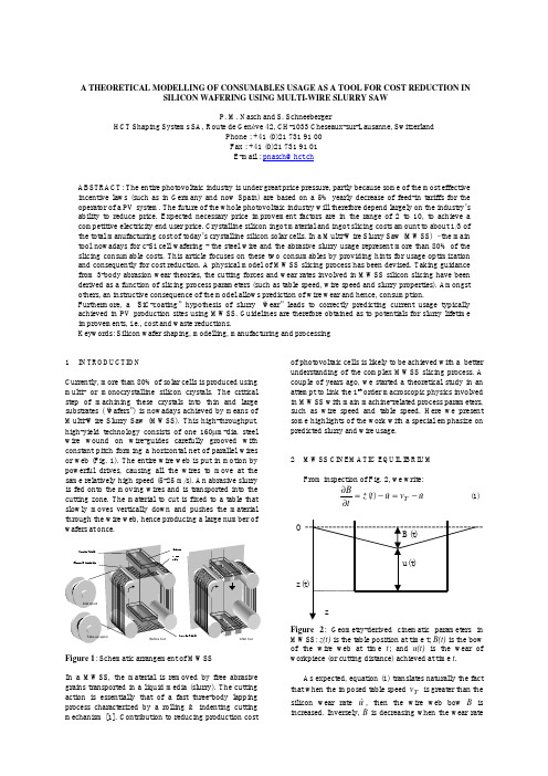
The MWSS “wear” is the distance u in the cutting direction. The wear rate, or cutting speed, is hence & = du dt . The total volume of wear or removed u material is from geometry Vu = K ⋅ L ⋅ u (Fig. 3). The volume-wear rate, or Material Removal Rate (also noted & = dV dt = K ⋅ L ⋅ u &. MRR) is V u u
vT =
π D
2 K
bPvf
(4)
This MWSS wear law expresses the proportionality between the table speed vT and the product P.vf under permanent regime. Experimental verification of (4) is illustrated in Fig. 4. This result is perfectly in line with recent work on multi-wire sawing [6, 7].
批注本地保存成功开通会员云端永久保存去开通
A THEORETICAL MODELLING OF CONSUMABLES USAGE AS A TOOL FOR COST REDUCTION IN SILICON WAFERING USING MULTI-WIRE SLURRY SAW P. M. Nasch and S. Schneeberger HCT Shaping Systems SA, Route de Genève 42, CH-1033 Cheseaux-sur-Lausanne, Switzerland Phone : +41 (0)21 731 91 00 Fax : +41 (0)21 731 91 01 E-mail : pnasch@hct.ch
- 1、下载文档前请自行甄别文档内容的完整性,平台不提供额外的编辑、内容补充、找答案等附加服务。
- 2、"仅部分预览"的文档,不可在线预览部分如存在完整性等问题,可反馈申请退款(可完整预览的文档不适用该条件!)。
- 3、如文档侵犯您的权益,请联系客服反馈,我们会尽快为您处理(人工客服工作时间:9:00-18:30)。
Int J Adv Manuf Technol(2015)80:1337–1346DOI10.1007/s00170-015-7089-zORIGINAL ARTICLEDepth of cut per abrasive in fixed diamond wire sawing Chunhui Chung1·Van-Nhat Le2Received:22August2014/Accepted:25March2015/Published online:19April2015©Springer-Verlag London2015Abstract Because of the high requirement for quality, the surfaces of prime wafers have to be flat and without damages.During the first machining process in wafer manu-facturing,the defects introduced by wire sawing must be removed by the subsequent lapping,grinding,and polis-hing processes.Therefore,the quality of sliced wafer is very important.Fixed diamond wire saw,on which the diamond grains are coated as abrasives,has become the major tool to slice ingot into wafers.Ductile-regime machining is an attractive process to achieve crack free surface on brittle materials in abrasive machining process.The depth of cut of the abrasive is a hint for the transition between ductile-and brittle-regime machining.In order to understand the cutting behavior in fixed diamond wire sawing,this paper presents an investigation of depth of cut per abrasive based on the wire profile model developed by the authors.The simulation results show that the larger depths of cut are unavoidable in fixed diamond wire sawing because of the random position and size distribution of diamond grains on the wire.Although the number of active abrasives and the depths of cut at the bottom of slicing groove are larger than those at the side of the groove,few larger diamond Van-Nhat Lelenhat@.vnChunhui Chungchunhui.chung@.tw1Department of Mechanical Engineering,National Taiwan University of Science and Technology,Taipei,Taiwan2Faculty of International Training,Thai Nguyen University of Technology,Thai Nguyen,Vietnam grains may introduce larger depths of cut and cracks on the side,which is the sliced wafer surface.Effects of pro-cess parameters to the depth of cut distributions are also analyzed.The variation in number of active abrasives in cutting zone as well as their depth of cut shows the pos-sibility to increase process productivity without increasing the depths of cut of the diamond grains.Consequently, the surface quality could be remained without further deterioration.Keywords Wire sawing·Diamond wire·Abrasive machining1IntroductionWire saw has been the prevailing tool to slice hard and brittle ingots into thin-disk wafers in semiconductor and photovoltaic pared to inner-diameter saw (ID saw),the main advantages of the wire sawing process are lower kerf loss and less wafer surface damage.When the wafer size is increased according to high demand of wafer production as well as the trend of cost reduction,the wire saw is expected to be the major tool to slice450mm sil-icon wafer[1].Furthermore,the diamond-coated wire has been utilized to replace slurry wire sawing process due to its high efficiency and less waste[2,3].Figure1is an SEM image of a diamond-coated wire and its model[4]. Figure2gives a schematic view of typical wire sawing process.Researchers have focused on different aspects of the wire sawing process which can be classified into mate-rial removal mechanism[5–7],process modeling[8–11], and parametric study between process inputs and outputsFig.1SEM image of a diamond-coated wire(left)and its model (right)[4][12–16].In order to fulfill the strict requirements in wafer surface quality,some studies concentrate the ways to mini-mize surface defects by controlling wire and process param-eters[5,13,14].Some suggestions have been made for improving surface quality[6,12,13].Increasing the wire speed and decreasing the feed rate are often recommended to achieve better sliced surface.However,most of these con-clusions are made based on experimental results.The trade-off between wafer surface quality and process productivity is still difficult to be balanced.A study of Gao et al.shows the possibility of optimal wire sawing process in which the ductile cutting happens mostly at the sides of the cutting groove and produces less damage on wafer surface.The brittle fracture at the bottom of the wire results in appropriate productivity[17].How-ever,the assumption that the abrasive grains are distributed evenly on the wire surface is far different from those on actual wire.In addition,the assumption that all of abrasive grains are assumed to be involving in cutting is impracti-cal because even a small difference in size or position of one abrasive could affect whether the abrasive contributes in cutting or not.When machining brittle materials with other processes such as turning and grinding,it is often possible to achieve pure ductile cutting regime by well-controlled depth of cut under certain value[18,19].It is doubtful whether the pure ductile machining exists in wire sawing or not,since the specific investigation of the depth of cut per abrasive in wire sawing is still absent,and most of sliced wafers still show a few cracks on the surfaces.The model of diamond-coated wire was proposed by the authors[4].This model successfully represents the surface of diamond-coated wire with the wire parameters including random characteristics in positions and sizes of the abra-sives.The slicing process has been simulated in other work of the authors[20]in which the sliced wafer surface is generated using the proposed wire model.In this study,the investigation of depth of cut per abra-sive during fixed diamond wire sawing is presented.The existence of abrasive in cutting zone as well as its ran-dom characteristics is considered in the model.The number of active abrasives,the depth of cut per abrasive,and the amount of material removed by each abrasive are defined by simulating one cross section of the ingot during slicing.The cutting groove is updated by the cutting behavior of each abrasive which is identified by both ploughing model and indentation fracture model proposed in the previous works. The results show that the brittle machining regime mainly contributes in material removal.The variation in number of active abrasives in cutting zone as well as their depth of cut show the possibility to increase process productiv-ity without decreasing the wafer surface quality.The effects of process parameters to the distributions of depth of cut are also discussed.The approach makes it possible to pre-dict the surface and subsurface damages in fixed diamond wire sawing with different slicing parameters.In addition, the depth of cut of all abrasives must be controlled to reduce the subsurface damage.2Model of material removal in abrasive machining of hard and brittle materialIn machining hard and brittle materials,ductile cutting regime exists at low depth of cut[19].Some research on ductile mode cutting of crystalline silicon have been reported[5,21,22].The critical depth of cut,at which the cutting mechanism transforms from purely ductile to brittle mode,depends on material property,tool shape,and cut-ting conditions.Higher depth of cut not only introduces the fractures and cracks beneath bulk material and result in higher material removal,but also increases wafer surface and subsurface damages.On the contrary,ductile-regime machining,which yields crack-free surface,is likely to hap-pen at the depth of cut lower than critical value.Priorwork Fig.2Schematic of multi-wire sawinghas been done to predict the critical depth for transition from ductile to brittle mode of cutting [19].d c =0.15EHK c H 2(1)where K c is the fracture toughness,H is the hardness,andE is the Young’s modulus of workpiece material.This expression,while useful,does not explicitly account for the effects of grain tip geometry and the friction to the critical depth of cut.Experimental works show that the critical depth of cut for hard material such as sin-gle crystal silicon,STV glass,and sapphire substrate are found to be between 0.1and 0.5μm [22].Diamond scrib-ing tests have been carried out,and the transitions between ductile and brittle cutting regimes on mono-crystalline sil-icon are under various depths of penetration for different conditions [5].The depth of cut of each abrasive directly identifies the cutting regime of that abrasive.The material removed from bulk material of each abrasive is varied and depends on whether the cutting mechanism in brittle mode or duc-tile mode.In ductile mode,the material removed area is estimated by projected area of the penetrated abrasive tip following the slicing direction as seen in Fig.3.In brittle mode,in which the depth of cut is higher than critical value,the cracks propagated during loading helps to remove more material.It is assumed that the amount of material above the lateral cracks,which is calculated by the depth of the lat-eral crack,h ,and the length of the lateral crack,c ,will be removed after unloading (also see Fig.3).The depth and the length of the lateral crack can be obtained by the following equations [23,24].h ≈b ≈⎡⎣ E H12H 12⎤⎦(cot ψ)13P 12(2)andc =⎛⎝ζ12L M14⎞⎠(cot ψ)512E 12K 12c H12P 58(3)Fig.3Indentation model of single pyramidal indenter [23]where ζL =25×10−3,M =34,E is the Young’s modu-lus,H is the hardness,and K c is the fracture toughness of workpiece material.The normal load on the abrasive required to penetrate the workpiece is P =12πa 2H =12π(g tan ψ)2H (4)in which a is the radius of contact area and g is the depth of penetration of the abrasive.The length of lateral crack,according to theoretical ana-lysis as shown in Eq.3,could be an impractical value since the coefficients remain unchanged regardless of material properties and scribing conditions.For example,the criti-cal depth of cut of 0.5μm will introduce the lateral length of 22.7μm based on Eq.3,which is quite different from the results in the experimental work conducted by Wu et al.[5].In this study,the length of lateral crack induced by each abrasive is assumed to be about the size of plastic zone,b ,based on diamond scribing test on silicon and subsurface stress analysis [5].3Modeling of the depth of cut per abrasive in fixed diamond wire sawing3.1Coordinate setting and definitions of wire and cutting groove profileOne cross section of the silicon ingot is considered during slicing as depicted in Fig.4.In the figure,v x is wire speed and v z is feed rate.The polar coordinate system is set with the origin O fixed at the wire center and the polar axis is aligned in lateral direction of the wire as seen in Fig.5.TheFig.4Simulating section of the ingot during slicingFig.5Coordinate setting for the simulationCartesian coordinate system is also employed with the sameorigin with the polar coordinate.Coordinate y is set hori-zontally to the right,and positive z is vertically down as the wire slicing direction.It is assumed that the slicing process is at a steady state,in which the rate of wire slicing into the workpiece is the same as the feed rate without further bending the wire.Let Δt be the time interval which is defined small enough to achieve appropriate accuracy in the simulation.In one time interval,the length of the wire crossing the simulating area can be estimated as:ΔL =v x Δt(5)where v x is the wire speed.At each step,a new wire profile will be generated by the method in Section 3.2.In this model,the peripheral profile of bottom of the cut-ting groove and the wire are divided by N point which are equivalent to (N −1)segments.The polar element angle of each segment is:Δθ=180◦N −1(6)Let W i θi ,r w i and T i θi ,r t ibe the two arrays present-ing the cutting groove and the wire profiles in which r w i and r t i are the radial distances from the i th point of the cutting groove and the wire profile to the coordinate ori-gin,respectively.The two profiles can be also converted to W i y w i ,z w i and T i y t i ,z t i ,respectively,in the Cartesian coordinate system (also see Fig.5).The polar angle spec-ifying the i th position on the cutting groove and the wire profile is calculated as:θi =(i −1)Δθ,i =i...N(7)The wire center is fixed at the coordinate origin during simulation.The relative motion between cutting groove and the wire profile is required to simulate process feed rate.Therefore,workpiece is moving in negative z direction withthe increase of time in this model.In each step,the transver-sal distance is calculated by the process feed rate and the time interval:Δz =v z Δt(8)where v z is the process feed rate.The cutting groove after transformation is identified based on Cartesian coordinate system,as shown in Fig.6:W i y w i ,z w i,t +Δt =W i y w i ,z wi −Δz,t (9)After the coordinate transformation,the polar angle specifying the position of cutting groove profile is changed from θi to θ i ,as depicted in Fig.6,which can be calculated as:θ i =arctan z w i −Δzy w i (t) ≈jΔθ(10)Because the transversal distance depends on the time interval setting value as well as the feed rate,the angle θ i will not be aligned with any of the polar angles which are defined according to the polar element angle Δθ.Therefore,the i th position of the array representing the cutting groove will be moved to the j th position which is closest to the updated data point and best presents the cutting groove point after coordinate transformation.3.2Generation of wire profileThe model of diamond-coated wire has been developed by the authors [4,20].This model was employed in this study to generate the surface profile of diamond-coated wire.The wire profile is formed depending on wire parameters including random characteristics of abrasives.The steel core diameter,wire outer diameter,the size,shape,and density of abrasive abrasives are the main parameters of diamond-coated wire.The shape of diamond abrasive variesandFig.6Coordinate trasformation of W i for each stepdirectly affects the cutting efficiency of the process.To sim-plify the model,all of the diamond abrasives are considered to be conical shape with the tip angle of 2ψ,and all abra-sives contact to wire core surface.In addition,the sizes of abrasive grains are assumed to follow the Gaussian distri-bution according to the previous works [26].At each time interval,the wire profile with the length ΔL was generated and projected to the simulating cross section to study the depth of cut per abrasive.The number of abrasives on the bottom half of the wire crossing the ingot during time interval can be estimated as:ΔK =ηπdΔL 2=ηπdv x Δt 2(11)where d is the diameter of wire core and ηis the diamond abrasive density.The random position of abrasives is defined by the possibility of existence of an abrasive,which is:s =ΔK N =ηπdv x Δt 2N(12)where N is the number of nodes on the peripheral surface of bottom half of the wire.If the existence of an abrasive at the i th point is con-firmed,then the abrasive size,r g ,will be identified accord-ing to probability density function as follows:p(r g )=1√2πσe−(μ+log (r g ))22σ2(13)where μand σare abrasive mean size and standard devia-tion of abrasive size range,respectively.The radial distance of abrasive tip to the center of the wire T i θi ,r t iis definedFig.7Defining wire profileFig.8Conflicts in identifying the wire profileas:r t i =d2+r g (14)The profile of diamond-coated wire at the neighboring points,j th ,is also updated according to the geometry of diamond abrasive as (Fig.7):r tj≈r t i −r t i θij cot ψ(15)There will be conflicts in updating radial profile if two abrasives are overlapped,as seen in Fig.8.In this case,the radial profile at the overlapped point,i th ,will be updated as:r t i =max r t iA ,r tiB (16)where r t iA and r t iBare two radial distances updated by the two overlapped abrasives A and B,respectively.3.3Updating cutting groove profile based by cutting regime of each abrasiveThe initial cutting groove profile W i θi ,r w iis defined by outer diameter of the wire,d o :r w i =d 02,i =1...N(17)If there exists an abrasive at the considering point,the depth of cut of the abrasive is defined by the disparity between the cutting groove and wire profile.It is assumed that the elastic deformation of the workpiece and the wire has no effect to the depth of cut of the active abrasives.Therefore,the depth of cut of an active abrasive is:g i =r t i −r wi (18)Fig.9Different cutting behaviors in cutting zone of wire sawing processThe cutting groove profile is updated based on the amount of material removed by individual active abrasive,as illustrated in Fig.9,which is identified according to cutting behaviors as follows:–No interaction between abrasive and workpiece (Abra-sive A):g i ≤0r w i =max r w i ,r t i=r w i (19)–Cutting regime is in ductile mode (Abrasive C):0≤g i ≤g c ,where g c is the critical value depth of cut,at which the cutting transits from ductile to brittle mode.r w i =max r w i ,r t i=r ti (20)–Cutting regime is in brittle mode (Abrasive B):g i >g c r w i =r w i +h(21)where h is the depth of lateral crack introduced by thecurrent abrasive,which can be obtained by Eq.2.For ductile machining,the profile of cutting groove is updated by the shapes of diamond grains.For brittle machining,the profile of cutting groove is updated accord-ing to the indentation cracking model as illustrated in Fig.3.4Simulation procedureFigure 10presents the simulation procedure of the proposed model.The simulation starts with the input of the wire and process parameters.The time interval and polar angle ele-ment are also defined in the simulation input stage.At each loop,the number of abrasives and the position and size of each abrasive grain are identified to generate new wire profile based on the given parameters.The cutting groove profile is then updated by the cutting behavior of individual abrasive and then transformed to the new coordinate by sim-ulating process feed rate.The positions of active abrasives and their depth of cut are recorded at eachstep.Fig.10Simulation procedure5Simulation resultsThe program of numerical simulation was compiled in MATLAB program.Three simulations have been conducted with different process parameters.The time interval,ele-ment polar angle,and total feed were set at 10−3s,0.1◦,and 500μm,respectively.The abrasive tip angle is assumed to be 90◦.The properties of single crystalline silicon are listed in Table 1.Table 2shows the parameters of the wire which were retrieved from SEM images.The critical depth of cut of single crystalline silicon is assumed to be 0.5μm accord-ing to the previous works [5,22].Different feed rate and wire speed were set as listed in Table 3in order to investigate the effects of these parameters to abrasive cutting behav-ior in wire sawing.Figure 11is an example of illustration during simulation.Table 1Material properties of single crystalline silicon [27]Young’s modulus Hardness Fracture toughness 127GPA10GPa0.7MPaTable2Wire saw parametersParameters Unit ValueWire outer diameterμm250 Core diameterμm190 Abrasive mean sizeμm50 Abrasive size rangeμm40–60 Abrasive density Abrasive/mm250The abrasives which contact the workpiece and con-tribute to material removal are considered as active abra-sives.We define active abrasive ratio as the ratio of the number of active abrasives to the number of all abrasives passing the cross section in the simulation.The simulation results of active abrasive rates are listed in Table4.These results indicate that the assumption of all abrasives involved in cutting in wire sawing process is impractical.Figures12,13,and14are the graphs of the depth of cut per abrasive during slicing with different feed rates and wire speeds.Although the cutting frequency with lower depth of cut is higher than that of with higher depth of cut,a lot of abrasives are still cutting with the depths of cut larger than critical value.Under different process parameters in the simulations,the number of brittle regime cutting abrasives always occupy a small portion of the total number of active abrasives.Thus,it seems impossible to obtain the pure duc-tile machining regime in wire sawing process.The surface and subsurface damages introduced by brittle cutting always take place in sliced wafer surface.Figure12shows the distribution of depth of cut under different feed rates.When doubling the feed rate,there is a significant decrease in number of abrasive cutting in duc-tile mode.The number of cutting abrasives with the depth of cut above1.4μm is larger with higher feed rate.How-ever,it is insignificant compared to the number of active abrasives in ductile mode.It is expected that these active abrasives in brittle mode contribute much more material removal than those in ductile mode.Figure13is the com-parison of the depth of cut distributions under different wire speeds.The plot shows the increasing number of ductile cut-ting abrasive when the wire speed is doubled.It is noted that increasing wire speed or decreasing feed rate increases sig-nificantly the number of ductile cutting abrasives while the Table3Process parameters in the simulationSimulation Wire speed Feed rate(m/s)(μm/s)A5 6.25B10 6.25C1012.5Fig.11Display of a simulation.The profile of diamond-coated wire was projected to the simulation sectionnumber of brittle cutting abrasives decreases,although the change is insignificant for brittle mode.However,the mate-rial removal still relies on brittle cutting regime even though the number of ductile cutting abrasives is large.When both feed rate and wire speed are doubled,the dis-tributions of the depth of cut seem unchanged as shown in Fig.14.According to Table4(simulation A and C), the average depth of cut and the active abrasive rate have not changed much when both increased feed rate and wire speed.This comparison shows that the process productivity can be increased without increasing damage on sliced wafer surface by increasing feed rate proportionally with respect to wire speed.This result is similar to other works based on the experimental results[12,14].The distribution of active abrasive in cutting zone is shown in Fig.15.The position angle is measured from the horizontal axis.There are more active abrasives at the bot-tom of the wire than those at other positions in cutting groove during slicing.The comparison between the number of active abrasive and the depth of cut in different area in cutting zone is shown in Fig.16.The ranges of side and bot-tom area of the cutting groove are defined from0◦to10◦for the side cutting and80◦to90◦for the bottom cutting.They have different numbers of active abrasives as well as the depth of cut per abrasive.More active abrasives with higher depth of cut take place at the bottom of cutting groove rather than the side.In addition,the depth of cut over2μm is almost not available in side cutting range.This result indi-cates that ductile-regime machining dominates the side-wall Table4Active abrasive ratio and average depth of cutSimulation Active abrasive ratio Average depth of cut(μm)A0.23%0.68B0.15%0.58C0.22%0.70Fig.12Comparison of depth of cut distribution under different feed rate (v x =10m/s and total feed of 500μm)cutting.However,large depth of cut still exists.This is the reason why the cracks on the sliced wafer surface always exist.6DiscussionFrom the simulation results,it is clear that the number of active abrasives and the depth of cut per abrasive depend on the interaction of wire speed and feed rate.In abrasive machining process,the number of active abrasives is not measurable,as well as the active abrasive ratio.This is the reason why we study this topic by simulations.The three simulation results are illustrated and compared in Figs.12,13,and 14.Either the double of wire speed or the half of feed rate increases the usage of wire length.However,the number of active abrasives is not proportional to theincreaseFig.13Comparison of depth of cut distribution under different wire speed (v z =6.25μm/s and total feed of 500μm)Fig.14Comparison of depth of cut distribution under different wire speed and feed rate (total feed of 500μm)of wire speed or inverse proportional to the decrease of feed rate.The reason is because of the transition between ductile-and brittle-regime machining.Higher feed rate will reduce the time of machining and the usage of wire.However,each abrasive must remove more material and penetrate deeper into the workpiece.It can be observed from Fig.12that the number of active abrasives with depth of cut over 1.4μm in higher feed rate is larger than that of in lower feed rate.These abrasives with larger depth of cut can remove much more material due to the brittle fracture.The decrease of wire speed also reduces the usage of wire length and num-ber of active abrasives,as shown in Fig.13.However,more active abrasives remove material with larger depth of cut,and more fracture are expected.During wire sawing process,the abrasives at the bottom of diamond-coated wire penetrate directly into the work-piece with the increase of feed.It is expected thattheseFig.15Distribution of active abrasives in cutting zone (v x =10m/s;v z =12.5μm/s and total feed of 500μm)Fig.16Number of active abrasives and the depth of cut in side and bottom cutting zone(v x=10m/s;v z=12.5μm/s and total feed of500μm)abrasives contribute most of material removal.For the abra-sives at the side,the motion of the diamond grains is parallel to the wall of slicing groove,which results in shallow depth of cut.Figure16illustrates the distribution of number of active abrasives with respect to the depth of cut.The num-ber of active abrasives in side cutting is less than that in bottom cutting.In addition,the number of active abrasives in side cutting reduces quickly with the increase of depth of cut.However,it is unavoidable that the larger depth of cut still happens occasionally in side cutting,which results in the cracks on the sliced wafer surface.Although the larger depth of cut cannot be avoided at the side of slicing groove,it is observed that the increase of wire speed and the decrease of feed rate can reduce the number of active abrasives with larger depth of cut.The trade-off between the process productivity and the wafer surface qual-ity can be discussed by the simulation results presented in this paper.The material removal can be maintained effec-tively while ductile-regime cutting dominates the two sides of the wire with the increase of wire speed to the machine limitation.Reduction of feed rate is an alternate method which also reduces the productivity,however.7ConclusionIn this paper,the model to investigate the depth of cut per abrasive has been developed.Different cutting behaviors of abrasive and their characteristics including random features in size and position are considered in the puter simulation has been employed to study the depth of cut per abrasive as well as its distribution.The conclusions are as follows:–The number of abrasives that contributes in cutting is small compared to the number of abrasives on the wire.More active abrasives take place on bottom of the wire than other positions during slicing.–Material removal during slicing is mainly contributed by brittle cutting regime.Pure ductile-regime machin-ing seems to be unattainable since the large depths of cut are frequently involved in slicing.–It is possible to increase the process productivity without increasing wafer surface and subsurface dam-ages because the distribution of depth of cut remains unchanged when increasing feed rate is proportioned with the wire speed.The approach presented in this study could be used to opti-mize practical wire sawing to increase process yield while limiting the wafer surface damage.References1.Goldstein M,Watanabe M(2008)450mm silicon waferschallenges—Wafer thickness scaling.In:Honolulu,HI,United states,2008.ECS transactions.Electrochemical Society Inc., pp3–132.Tso P-L,Yan B-H(2005)A study of slicing process with thindiamond wire.In:3rd international conference on leading edge manufacturing in21st century,LEM,Nagoya,Japan,2005.Japan Society of Mechanical Engineers,pp619–6243.Sugawara J,Yamakawa M,Mizoguchi A(2001)Development offixed-abrasive grain wire saw.SEI Tech Rev52:87–904.Chung C,Nhat LV(2013)Surface generation of diamond coatedwire for wire sawing process.In:16th international conference on advances in materials and processing technologies.AMPT,Taipei, p20135.Wu H,Melkote SN(2008)Study of ductile-to-brittle transition insingle grit diamond scribing of silicon:Application to wire sawing of silicon wafers.J Eng Mater Technol134(4):1–86.Gao Y,Ge P,Li S(2009)Investigation of subsurface damagedepth of single crystal silicon in electroplated wire saw slicing.In:15th conference on abrasive technology in China:advances in grinding and abrasive technology,Laubisrutistr.24,Stafa-Zuerich, CH-8712,Switzerland,2009.Key engineering materials.Trans Tech Publications Ltd,pp306–3107.Chung C(2012)Abrasive distribution of the fixed diamond wirein wire sawing process.Adv Mater Res579:145–1528.Li J,Kao I,Prasad V(1998)Modeling stresses of contacts inwire saw slicing of polycrystalline and crystalline ingots:applica-tion to silicon wafer production.J Electron Packag120(2):123–1289.Liedke T,Kuna M(2011)A macroscopic mechanical model of thewire sawing process.Int J Mach Tools Manuf51(9):711–720 10.Liedke T,Kuna M(2013)Discrete element simulation ofmicromechanical removal processes during wire sawing.Wear 304(1–2):77–8211.Nassauer B,Hess A,Kuna M(2014)Numerical and experimentalinvestigations of micromechanical processes during wire sawing.Int J Solids Struct51(14):2656–266512.Teomete E(2011)Effect of process parameters on surface qualityfor wire saw cutting of alumina ceramic.Gazi University J Sci 24(2):291–297。