罗斯蒙特 -温度产品-2008
罗斯蒙特仪表系统设置技术通告
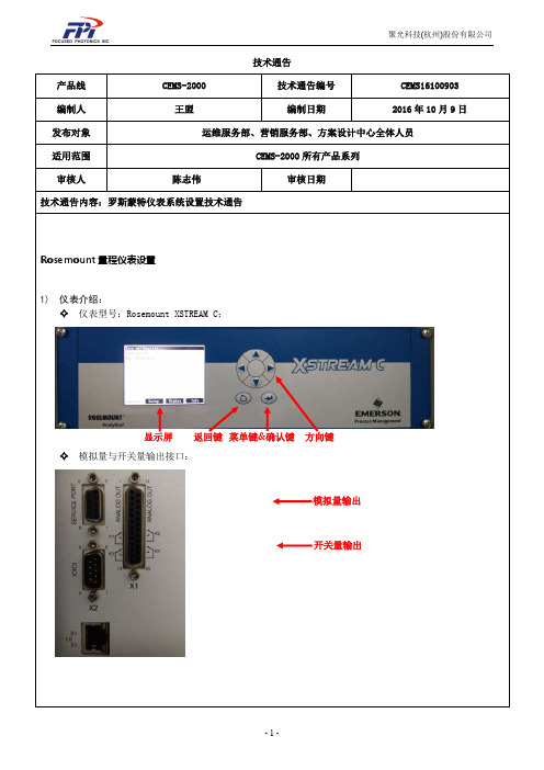
技术通告产品线 CEMS-2000 技术通告编号 CEMS16100903 编制人 王盟编制日期2016年10月9日发布对象 运维服务部、营销服务部、方案设计中心全体人员适用范围 CEMS-2000所有产品系列审核人陈志伟 审核日期技术通告内容:罗斯蒙特仪表系统设置技术通告Rosemount 量程仪表设置1) 仪表介绍:✧ 仪表型号:Rosemount XSTREAM C;✧ 模拟量与开关量输出接口:显示屏返回键 菜单键&确认键 方向键模拟量输出开关量输出✧按键说明:在测量界面按进入菜单,按为返回或取消在具体对某项设置时与是对数字位数的选择,与具有调节数字大小或者选择某个组分的功能。
仪表上电需要预热,测量主界面上的“Temperature”(温度)达到46℃左右时才算预热结束,此时才能进行调零和标定操作。
2)上电设置✧单位设置(设为ppm):(测量主界面)测量主界面按 进入菜单Control(操作)按切换到Setup(设置) 选中 Display(显示),按进入配置,选中 Unit(单位)按键来切换到ppm量程设置:测量主界面按 Control(操作),然后按切换到Setup(设置)点确定点选中In/Outputs(输入输出)点确定。
选中Analog outputs(模拟量输出)按键,选择相应的组分,因子输出顺序和测量界面因子顺序一致分别设置“LowScale”(量程下限)和“HowScale”(量程上限)按上、下键进行量程的修改,键确认更改设置,按保存。
开关量设置:测量主界面按键Control(操作) → 按切换到Setup(设置) →点选中In/Outputs(输入输出)点确定, 选中Digital outputs(数字量输出)按进行配置。
超低开关量配置:Output2(第二输出)按进行设置,按上、下键调为Fail(仪表故障) → 按保存 →Output4(第四输出)设置为AutoC(自动调零)→Output1(第一输出)和Output3(第三输出)设置为Blank(空)→ 按确认键保存常规开关量配置:Output1(第一输出)设置为Fail(仪表故障) → 按保存 →Output2(第二输出)设置为AutoC(自动调零)→Output3(第三输出)和Output4(第四输出)设置为Blank(空)→ 按确认键保存(操作方法同上) 超低仪表和常规仪表如何区分:1、开关量和模拟量开关接口(超低仪表) (常规仪表)2、自动调零时间(超低仪表) (常规仪表)自动调零时间单位不同,超低仪表单位为M;常规仪表单位为h,且不可更改。
罗斯蒙特产品选型
3051TG3A2B21AS1B4E5 1199WAC51ARTW30DAA5B
3051TG5A2B21AS1B4E5
1199WAC51ARTW32DAA5B
3051TG2A2B21AB4 4 压力变送器
3051TG5A2B21AB4E5
248HAE5U2XA
5
温度变送器
0065N33N0000D0200W12A1E5XA 248HAE5U2XA
0065N33N0000D0100W12A1E5XA
6 HART 手操器 475HP1ENA9GM9
固定点式红外 7 可燃气体探测 Ultima-XIR、9020、R10
器
8
便携式可燃气 体检测仪
ORIONPLUS
9 磁翻柱液位计 UHZ-518A11618070/2
测量范围
单 位
数数 量量 12
厂家
备注
0-18000 0-15000
台 22
配套提供与过程引
台
44
罗斯蒙
压管连接的活动接 头
特
台2
配套提供配对安装 法兰及紧固件
0-1MPa 台 17
0-1.5MPa
台 台 台
2
17 2
罗斯蒙 特
配套提供与过程引 压管连接的活动接 头
0-30MPa 台 4
台
4
0-1MPa 0-30MPa
台1 台1
罗斯蒙 特
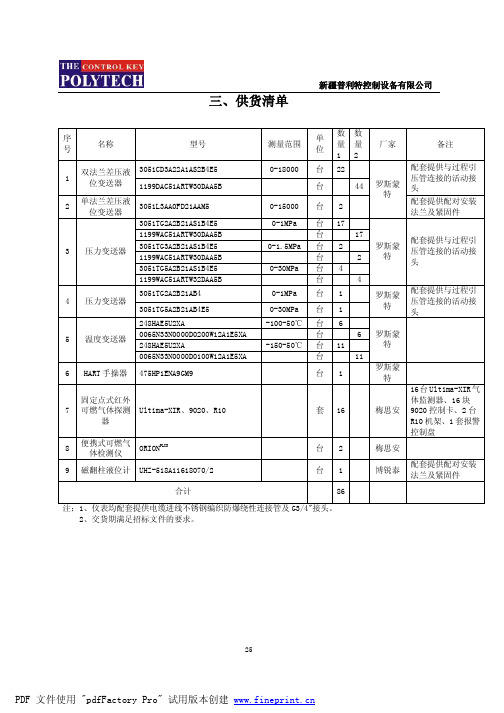
三、供货清单
新疆普利特控制设备有限公司
序 号
名称
型号
1
双法兰差压液 3051CD3A22A1AS2B4E5 位变送器 1199DAC51ARTW30DAA5B
2
单法兰差压液 位变送器
(完整word版)罗斯蒙特质量流量计操作说明
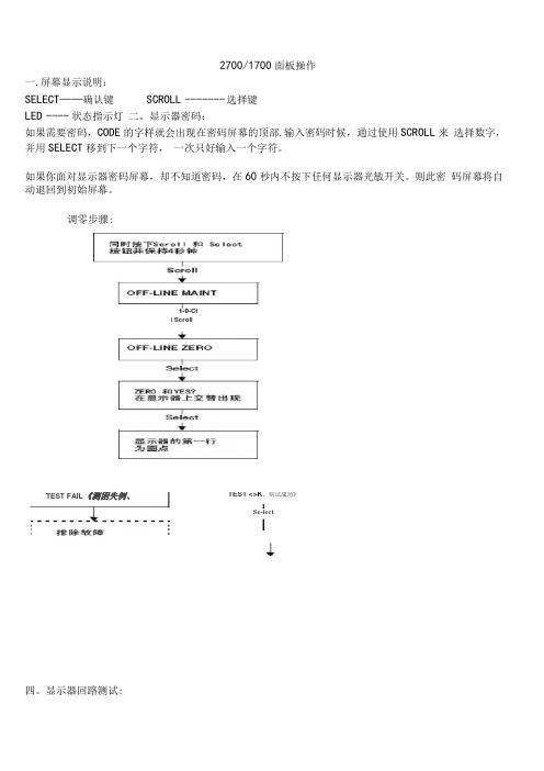
2700/1700面板操作一.屏幕显示说明:SELECT——确认键SCROLL ------- 选择键LED ---- 状态指示灯二。
显示器密码:如果需要密码,CODE的字样就会出现在密码屏幕的顶部.输入密码时候,通过使用SCROLL来选择数字,并用SELECT移到下一个字符,一次只好输入一个字符。
如果你面对显示器密码屏幕,却不知道密码,在60秒内不按下任何显示器光敏开关。
则此密码屏幕将自动退回到初始屏幕。
调零步骤:四。
显示器回路测试:TEST <>K。
则试成功》ISe-lectI1-0-CtI ScrollTEST FAIL《测困失例、五. Set MA01Set MA024 mA12 mA20 mASe eelScroll3e eel正码?二>SelectScrollOFF-LINE SIMSelectScrollScroll1 KMzIDKHzSclent读取接受设餐的输出HPYesSst D01Set D02SelectScrollOHOFP阱I M]读取接克设备的箍出致T回路测试成功女%,人出?狂.停止历具ScrollExh检登回率接线排除输出故慎显示器查看报警:LED指示灯状态及报警查看状态指示灯的状态报警优先级魄色无报警-正常运行模式鼻电闪姆”已改正但尚未信认的状态黄色已偏认的低强度报警黄色闪探⑴未稳认的做强度报警虹笆己碉认的高强度指警红色闪峭'未询认的高强虚报警11)如果报警菜单被禁止,则无沫箱认报警,在这种情况下.状态指示LEim不再闪保工报警按照报警队列中的优先级排列,要查看队列中某指定报警:L同时按下配Ml和Select按钮,当屏幕上出现"EE ALARM'」札松开按钮“ 参阅图7-1.2 .按Select按钮,3 .如果屏幕上交替出现“AGK ALL”时,则按配FQ11按钮,4 .如果屏幕上出现"0 ALARN” ,则到第6步,5,按配ell按钮查看队列中的每个技警.要了解显示帚显示的报警代码的含义请参阅翦1QJ1幸节,6,按Scroll按钮直到解幕上出现“EXIT” ”7.按Select按祗六.管理累积量和库存量:(完整word 版)罗斯蒙特质量流量计操作说明宫动/停止所有累租值和质存量⑵进行酬重副可定翻值出现空位七:测量单位设置:SELECT+SCROLL 按 4 秒 ----- ► SEE ALARM ---- ► [SCROLL] ---- ►OFFLINE MAINTAIN -------- ► [SELECT]- ..... > [SCROLL] ----- ►CONFIG ----- ► [SELECT] ---- ► MASS ------- [SELECT] ------- ►SELECTI 如果有需求.输入密码SELECTSELECT如果有需求,输入密码SELECTSELECT复位!特定累积值⑴深部翻屏直到特定累积值可以按SCROLL选择你要的单位> 选定后按SELECT按SCROLL 直到出现EXIT ----- ► [SELECT]体积单位和密度单位设置和上述步骤相同八量程设置(LRV URV)[SELECT+SCROLL] 按 4 矛秒/ SEE ALARM ------- ► [SCROLL] --- ►OFFLINE MAINTAIN --------- ► [SELECT^ ------ ►继续按SCROLL 直到出现MAO1[SELECT] ----------------------------- k SRC MAO1 ------ k [SELECT]MFLOW ---- ► [SELECT]----- SRC MAO1 ——[SCROLL]4 MAO1 ----- ►输入最小量程------ ►[SCROL L+SELEC T] 4 MAO1 ------- ► [SCROLL] ------ ►——20HMAO1 ----------- ►[SELECT] 输入最大量程------ ►[SELECT+SCROLL]--------------- > 20 MAO1>[SCROLL]EXIT ---- ^ 按SELECT 退出.其他量程设置和上述步骤相同。
美国罗斯蒙特传感器型号

美国罗斯蒙特Rosemount 3051,1151压力/差压变送器,产品有3051C,3051S系列,1151智能压力变送器,2088绝压/表压智能压力变送器,3095MV多变量质量流量变送器,4600石油与天然气压力变送器,4500卫生型压力变送器,1810嵌入式安装压力变送器。
性能优异:精度0.075%量程比100:1差压:校验量程从0.5inH2O至2000psi表压:校验量程从2.5inH2O至2000psi绝对压力:校验量程从0.167psia至4000psia过程隔离膜片:不锈钢,哈氏合金CR,蒙乃尔R,钽(仅限CD,CG)及镀金蒙乃尔设计小巧、坚固而质轻,易于安装3051S压力变送器系列1.工业标准产品,提供无以匹敌的性能与可靠性;2.同类产品性能最优,精度高达0.025%;3.规模可变平台,具有HART、基金会现场总线,过程诊断与安全认证证书;4.共面法兰设计把阀组,密封件(膜盒)与一次元件一体化成为单个组合件.3051C型差压、表压与绝压变送器1.性能优异:精度0.4%2.总体性能高达0.125%,五年稳定性3.共平面平台允许将阀组、一次元件和远传装置一体化4.校验量程从0.1inH2O至4000psia(25Pa到27.6mPa)5.过程隔离膜片:316L不锈钢,哈氏合金C,蒙乃尔,钽(仅限CD,CG)及镀金蒙及尔,镀金不锈钢6.设计小巧、坚固而质轻,易于安装7.复合量程(仅限CD、CG),可测量负压3051T型表压与绝压变送器1.性能优异:精度0.04%2.绝压:校验量程从0.3至10,000psia3.不锈钢与哈氏合金C过程隔离膜片4.灌充液:硅油与惰性液5.可选DIN和与压力反应罐相配的过程相连3051L型液位变送器1.液位测量精度达0.075%2.校验量程从0.25inH2O垤8310inH2O3.平膜片式,2-,4-,与英寸伸出式膜片4.多种灌充液可选,可满足不同应用场合要求5.小巧而质轻,易于安装与维护6.接液件材料:316L不锈钢,哈氏合金和钽1151DP、GP和AP型差压、表压和绝压变送器1.性能优越:精度0.075%,量程比50:12.差压测量范围:30inH2O至1,000psi(7.5-6895kPa)3.表压测量范围:30inH2O至6,000psi(7.5-41369kPa)4.绝压测量范围:150inH2O至1,000psi(37.4-6895kPa)1151HP型高静压差压变送器1.性能优越:精度0.075%,量程比50:12.差压测量范围:150inH2O至300psi(37.3-2068kPa)3.在4500psi(31Mpa)高静压下,可实现差压的精确测量1151LT型法兰安装式液位变送器1.液位测量精度0.25%2.测量范围:0-25至0-2,770inH2O (0-6.2至0-690kPa)3.平膜片式,2-,4-和6-英寸伸出式膜片4.多种灌充液选择,可满足各种应用要求5.阻尼可调6.接液件材料:不锈钢,哈氏合金C-276和钽2088绝压/表压智能压力变送器——1. 绝压和表压测量10.3Kpa至27.6Mpa2. 0.1%参考精度(0.075%高精度选项)3. 20:1量程比4. 采用HART通讯协议5. 外部零部和量程调整6. 可选的液晶表头(刻度可调)7. 超过35年的变送器制造经验,工业领域中完善的服务和支持网络美国罗斯蒙特3051C,3051S压力变送器美国罗斯蒙特2088绝压/表压智能压力变送器美国罗斯蒙特4600石油与天然气压力变送器美国罗斯蒙特4500卫生型压力变送器美国罗斯蒙特1151智能压力变送器美国罗斯蒙特3095MV多变量质量流量变送器美国罗斯蒙特375手操器罗斯蒙特Saab Rex计量级雷达液位计罗斯蒙特5600 过程级雷达液位计罗斯蒙特3300导波雷达液位计罗斯蒙特PRO库存管理级雷达罗斯蒙特P/H 分析仪罗斯蒙特3244MV 基金会现场总线型多参数温度变送器罗斯蒙特244EH型和244ER型248型为PC机可编程温度变送器罗斯蒙特484T型644H型和644R型智能温度变送器罗斯蒙特3144/3244 温度变送器美国罗斯蒙特质量流量计美国罗斯蒙特流量计算机美国丹尼尔超声波气体流量计罗斯蒙特8800型质量流量计罗斯蒙特8700系列电磁流量计罗斯蒙特阿牛巴3095MFA质量流量计罗斯蒙特阿牛巴3051SFA体积流量计罗斯蒙特3095MFC孔板质量流量计罗斯蒙特3051SFC孔板流量计罗斯蒙特高准公司R系列质量流量计罗斯蒙特RFT9739高准质量流量和密度变送器。
罗斯蒙特3144P温度传感器说明书
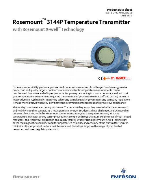
Product Data Sheet00813-0100-4021, Rev SBApril 2019 Rosemount™ 3144P Temperature Transmitter with Rosemount X-well™ TechnologyFor every responsibility you have, you are confronted with a number of challenges. You have aggressive production and quality targets, but inaccurate or unavailable temperature measurements create unscheduled downtime and off-spec products. Loops may be running in manual because you don’t trust your temperature measurement, requiring the attention of your maintenance staff and costing money in lost production. Additionally, improving safety and complying with government and company regulations is made more difficult when you don’t have the information or tools needed to prove your compliance. That is why companies are coming to Emerson™ – because they know they need reliable measurements and visibility into their temperature measurements in order to address these challenges and achieve their business objectives. With the Rosemount 3144P Transmitter, you gain greater visibility into your temperature processes so you can improve safety, comply with regulations, make the most of your limited resources, and reach your production and quality targets. By leveraging Rosemount X-well Technology, advanced diagnostic capabilities and the unparalleled reliability and accuracy of the transmitter, you can minimize off-spec product, reduce maintenance and downtime, improve the usage of your limited resources, and meet regulatory demands.Features and benefitsRosemount X-well ™Technology provides a Complete Point Solution ™foraccurately measuring process temperature in monitoring applications withoutthe requirement of a thermowell or process penetration.■Simplify temperature measurement point specification, installation andmaintenance, and eliminate possible leak points.■Calculates a repeatable and accurate process temperature measurement via an in-transmitter thermal conductivity algorithm.■Measures pipe surface and ambient temperature, and utilizes the thermalconductivity properties of the installation and process piping in order to provide an accurate process measurement.ContentsFeatures and benefits........................................................................................................................................................................2Ordering information........................................................................................................................................................................5How to order Rosemount X-well ™Technology...................................................................................................................................9Specifications..................................................................................................................................................................................10Product Certifications......................................................................................................................................................................23Dimensional drawings (34)April 2019Industry-leading temperature transmitter delivers unmatched field reliability and innovative process measurement solutions■Superior accuracy and stability■Dual and single sensor capability with universal sensor inputs (RTD, T/C,mV, ohms)■Comprehensive sensor and process diagnostics offering■SIL3 Capable: IEC 61508 certified by an accredited 3rd party agency for usein safety instrumented systems up to SIL 3 (minimum requirement of single use [1oo1] for SIL 2 and redundant use [1oo2] for SIL 3)■Dual-compartment housing ■Large LCD display■4–20 mA /HART ® with selectable revisions (5 and 7)■F OUNDATION ™Fieldbus, compliant to ITK 6.0 and NE107 standardsImprove efficiency with best-in-class product specifications and capabilities■Reduce maintenance and improve performance with industry leading accuracy and stability.■Improve measurement accuracy by 75 percent with transmitter-sensor matching.■Ensure process health with system alerts and easy to use device dashboards.■Easily check device status and values on local LCD display with large percent range graph.■Achieve high reliability and installation ease with the industry's most rugged dual compartment design.Optimize measurement reliability with diagnostics designed for any protocolon any host system■Thermocouple degradation diagnostic monitors the health of athermocouple loop, enabling preventative maintenance.■Minimum and maximum temperature tracking tracks andrecords temperature extremes of the process sensors and the ambient environment.■Sensor drift alert detects sensor drift and alerts the user.■The Hot Backup ™ feature provides temperature measurementredundancy.April 2019Explore the benefits of a Complete Point Solution from Emerson■An “Assemble To Sensor” option enables Emerson toprovide a complete point temperature solution, delivering an installation-ready transmitter and sensor assembly.■Emerson offers a selection of RTDs, thermocouples, andthermowells that bring superior durability and Rosemount reliability to temperature sensing, complementing theRosemount Transmitter portfolio.Experience global consistency and local support from numerous worldwideEmerson manufacturing sites■World-class manufacturing provides globally consistentproduct from every factory and the capacity to fulfill the needs of any project, large or small.■Experienced instrumentation consultants help select theright product for any temperature application and advise on best installation practices.■An extensive global network of Emerson service and supportpersonnel can be on-site when and where they are needed.■Make wireless installation and configuration easy with theEmerson Wireless Gateway.Looking for a wireless temperature solution? For wireless applications that require superior performance and unmatched reliability,consider the Rosemount 648 Wireless Temperature Transmitter .April 2019April 2019Ordering informationRosemount™ 3144P Temperature TransmitterSpecification and selection of product materials, options, or components must be made by the purchaser of the equipment. See for more information on material selection. When ordering Rosemount X-well™ Technology, specific option codes are required. See for more information.Table 1: Rosemount 3144P Temperature Transmitter Ordering InformationThe starred offerings (H) represent the most common options and should be selected for best delivery. The non-starred offerings are subject to additional delivery lead time.April 2019(1)When IS approval is ordered on a Foundation Fieldbus, both standard IS and FISCO IS approvals apply. The device label is marked appropriately.(2)Consult factory for availability when ordering with HART or F OUNDATION Fieldbus models.Table 2: Options (include with selected model number)April 2019(1)Not available with F OUNDATION Fieldbus models.(2)Enhanced accuracy only applies to RTDs, however the option can be ordered with any sensor type.(3)Available with Intrinsically Safe approvals only. For FM Intrinsically Safe or non-incendive approval (option code I5), install in accordance withRosemount drawing 03151-1009 to maintain 4X rating.April 2019April 2019How to order Rosemount X-well™ TechnologyRosemount X-well Technology is for temperature monitoring applications and is not intended for control or safety applications. It is available in the Rosemount™ 3144P Transmitter in a factory assembled direct mount configuration with a Rosemount 0085 Pipe Clamp Sensor. It cannot be used in a remote mount configuration. Rosemount X-well Technology will only work as specified with factory supplied and assembled Rosemount 0085 Sensor silver tipped single element sensor with an 80 mm extension length. It will not work as specified if used with other sensors.Table 3: Rosemount 3144P X-well Technology Option Code RequirementsTable 4: Rosemount 0085 Pipe Clamp Sensor Option Code Requirements for Use with X-well TechnologyRosemount X-well assemblies are available in most Rosemount 0085 Pipe Clamp Sensor diameter sizes.April 2019 SpecificationsHART® and F OUNDATION™ FieldbusFunctional specificationsInputsUser-selectable. See for sensor options.OutputTwo-wire device with either 4–20 mA/HART, linear with temperature or input, or completely digital output with F OUNDATION Fieldbus communication (ITK 6.0.1 compliant).IsolationInput/output isolation specified to 500 Vdc (500 Vrms 707 V peak) at 50/60 Hz.Humidity limits0–99 percent relative humidity, non-condensingUpdate timeApproximately 0.5 second for a single sensor (one second for dual sensors).Physical specificationsMaterial selectionEmerson provides a variety of Rosemount™ products with various product options and configurations including materials of construction that can be expected to perform well in a wide range of applications. The Rosemount product information presented is intended as a guide for the purchaser to make an appropriate selection for the application. It is the purchaser’s sole responsibility to make a careful analysis of all process parameters (such as all chemical components, temperature, pressure, flow rate, abrasives, contaminants, etc.), when specifying product, materials, options and components for the particular application. Emerson is not in a position to evaluate or guarantee the compatibility of the process fluid or other process parameters with the product, options, configuration or materials of construction selected.Conformance to specification (±3σ [Sigma])Technology leadership, advanced manufacturing techniques, and statistical process control ensure specification conformance to at least ±3σ.Conduit connectionsThe standard field mount housing has ½–14-in. NPT conduit entries. Additional conduit entry types are available, including PG13.5 (PG11), M20 3 1.5 (CM20), or JIS G ½. When any of these additional entry types are ordered, adapters are placed in the standard field housing so these alternative conduit types fit correctly. See for dimensions.Materials of constructionEnclosure Low-copper aluminum CF-8M (cast version of 316 stainless steel)Paint PolyurethaneO-rings Buna NMounting specificationTransmitters may be attached directly to the sensor. Optional mounting brackets (codes B4 and B5) allow for remote mounting. SeeTransmitter weightAluminum 3.1 lb (1.4 kg)Stainless steel7.8 lb (3.5 kg)Enclosure ratingsType 4XIP66 and IP68StabilityRTDs:±0.1 percent of reading or 0.1 °C (0.18 °F), whichever is greater, for two years for RTDs. Thermocouples:±0.1 percent of reading or 0.1 °C (0.18 °F), whichever is greater, for one year for thermocouples.Five-year stabilityRTDs:±0.25% of reading or 0.25 °C, whichever is greater, for five years.Thermocouples:±0.5% of reading or 0.5 °C, whichever is greater, for five years.Vibration effectTested to the following with no effect on performance per IEC 60770-1, 1999:Self calibrationThe analog-to-digital measurement circuitry automatically self-calibrates for each temperature update by comparing the dynamic measurement to extremely stable and accurate internal reference elements.RFI effectWorst case RFI effect is equivalent to the transmitter’s nominal accuracy specification, according to , when tested in accordance with IEC 61000-4-3, 30 V/m (HART)/20 V/m (HART T/C) /10 V/m (F OUNDATION Fieldbus), 80 to 1000 MHz, with unshielded cable. CE electromagnetic compatibility compliance testingThe Rosemount 3144P meets or exceeds all requirements listed under IEC 61326: 2006.External ground screw assemblyThe external ground screw assembly can be ordered by specifying code G1. However, some approvals include the ground screw assembly in the transmitter shipment, hence it is not necessary to order code G1. The table below identifies which approval options include the external ground screw assembly.(1)The parts contained with the G1 option are included with the Integral Protector option code T1. When ordering T1, the G1 option code does notneed to be ordered separately.Hardware tag■No charge■Two lines of 28 characters (56 characters total)■Tags are stainless steel■Permanently attached to transmitter■Character height is 1/16-in. (1.6 mm)■ A wire-on tag is available upon request. Five lines of 12 characters (60 characters total)Software tag■HART® transmitter can store up to eight characters in HART 5 mode and 32 characters in HART 7 mode. F OUNDATION Fieldbus transmitters can store up to 32 characters.■Can be ordered with different software and hardware tags.■If no software tag characters are specified, the first eight characters of the hardware tag are the default.Transmitter accuracyTable 5: Transmitter Accuracy(1)No minimum or maximum span restrictions within the input ranges. Recommended minimum span will hold noise within accuracy specificationwith damping at zero seconds.(2)Digital accuracy: digital output can be accessed by the Field Communicator.(3)Enhanced accuracy can be ordered using the P8 Model Code.(4)Total Analog accuracy is the sum of digital and D/A accuracies.(5)Applies to HART/4–20 mA devices.(6)Total digital accuracy for thermocouple measurement: sum of digital accuracy +0.25 °C (0.45 °F) (cold junction accuracy)(7)Digital accuracy for NIST Type B is ±3.0 °C (±5.4 °F) from 100 to 300 °C (212 to 572 °F).(8)Digital accuracy for NIST Type K is ±0.50 °C (±0.9 °F) from –180 to –90 °C (–292 to –130 °F).Reference accuracy example (HART Protocol only)When using a Pt 100 (α = 0.00385) sensor input with a zero to 100 °C span: Digital Accuracy would be ±0.10 °C, D/A accuracy would be ±0.02% of 100 °C or ±0.02 °C, Total = ±0.12 °C.Differential capability exists between any two sensor types (dual-sensor option)For all differential configurations, the input range is X to Y where:■X = Sensor 1 minimum – Sensor 2 maximum and■Y = Sensor 1 maximum – Sensor 2 minimumDigital accuracy for differential configurations (dual-sensor option, HART Protocol only)■Sensor types are similar (e.g., both RTDs or both T/Cs): Digital Accuracy = 1.5 times worst case accuracy of either sensor type ■Sensor types are dissimilar (e.g., one RTD, one T/C): Digital accuracy = Sensor 1 accuracy + Sensor 2 accuracyAmbient temperature effectTransmitters may be installed in locations where the ambient temperature is between –40 and 85 °C (–40 and 185 °F). To maintain excellent accuracy performance, each transmitter is individually characterized over this ambient temperature range at the factory. Table 6: Ambient Temperature Effect on Digital Accuracy(1)Change in ambient is in reference to the calibration temperature of the transmitter (20 °C [68 °F]).(2)Ambient temperature effect specification valid over minimum temperature span of 28 °C (50 °F).(3)Applies to HART/4–20 mA devices.Process temperature effectsTable 7: Ambient and Process Temperature Difference Effect on Digital Accuracy(1)Valid under steady state process and ambient conditions.Temperature effects exampleWhen using a Pt 100 (α = 0.00385) sensor input with a 0 to 100 °C span at 30 °C ambient temperature, the following statements would be true:Digital temp effects■0.0015 °C/°C x (30 - 20 °C) = 0.015 °CD/A effects (HART/4–20 mA only)■[0.001%/°C of span] x 100 °C x |(30 - 20 °C)| = °C DA effect■[0.001%/°C x 100] x |(30 - 20)| = 0.001 °CWorst case error■Digital + D/A + Digital temp effects + D/A effects= 0.10 °C + 0.02 °C + 0.015 °C + 0.01 °C = 0.145 °CTotal probable error■Rosemount X-well temperature effects exampleWhen using Rosemount X-well Technology at 30 °C ambient temperature and 100 °C process temperature:Digital ambient temperature effects:■0.0058 °C x (30 - 20) = 0.058 °CProcess temperature effects:■0.01 °C x (100 - 30) = 0.70 °CWorst case error:■Digital accuracy + Digital ambient temperature effects + Process temperature effects =0.29 °C + 0.058 °C + 0.70 °C = 1.05 °CTotal probable error:■HART/4-20 mA specificationsPower supplyExternal power supply required. Transmitters operate on 12.0 to 42.4 Vdc transmitter terminal voltage (with 250 ohm load, 18.1 Vdc power supply voltage is required). Transmitter power terminals rated to 42.4 Vdc.Wiring diagramSee Figure 7.AlarmsCustom factory configurations of alarm and saturation levels are available for valid values with option code C1. These values can also be configured in the field using a Field Communicator.Transient protection (option code T1)The transient protector helps to prevent damage to the transmitter from transients induced on the loop wiring by lightning, welding, heavy electrical equipment, or switch gears. The transient protection electronics are contained in an add-on assembly that attaches to the standard transmitter terminal block. The external ground lug assembly (code G1) is included with the transient protector. The transient protector has been tested per the following standard:■IEEE C62.41-1991 (IEEE 587)/location categories B3. 6 kV/3 kA peak (1.2 x 50 μS Wave 8 x 20 μS combination wave) 6 kV/0.5 kA peak (100 kHz ring wave) EFT, 4 kV peak, 2.5 kHz, 5 x 50 nS■Loop resistance added by protector: 22 ohmsmax.■Nominal clamping voltages: 90 V (common mode), 77 V (normal mode)Local displayOptional five-digit LCD display includes 0–100% bar graph. Digits are 0.4 inches (8mm) high. Display options include engineering units (°F, °C, °R, K, ohms, and millivolts), percent, and milliamperes. The display can also be set to alternate between engineering units/milliamperes, Sensor 1/Sensor 2, Sensor 1/Sensor 2/Differential Temperature, and Sensor 1/Sensor2/Average Temperature. All display options, including the decimal point, may be reconfigured in the field using a Field Communicator or AMS Device Manager.Turn-on timePerformance within specifications is achieved less than six seconds after power is applied to the transmitter when the damping value is set to zero seconds.Power supply effectLess than ±0.005 percent of span per volt.SIS safety transmitter failure valuesIEC 61508 Safety Certified SIL 2 and SIL 3 Claim Limit■Safety accuracy: Span ≥ 100 °C: ±2% of process variable span■Span < 100 °C: ±2 °C■Safety response time: five seconds■Safety specifications and FMEDA report available at /Rosemount/Safety■Software suitable for SIL3 applicationsTemperature limitsTable 8: Temperature Limits(1)LCD display may not be readable and LCD display updates will be slower at temperatures below –4 °F (–20 °C).Field Communicator connectionsField Communicator connections are permanently fixed to power/signal block.Failure modeThe Rosemount 3144P features software and hardware failure mode detection. An independent circuit is designed to provide backup alarm output if the microprocessor hardware or software fails.The alarm level is user-selectable using the failure mode switch. If failure occurs, the position of the hardware switch determines the direction in which the output is driven (HIGH or LOW). The switch feeds into the digital-to-analog (D/A) converter, which drives the proper alarm output even if the microprocessor fails. The values at which the transmitter drives its output in failure mode depends on whether it is configured to standard, or NAMUR-compliant (NAMUR recommendation NE 43) operation. The values for standard and NAMUR-compliant operation are as follows:Table 9: Operation Parameters(1)Measured in milliamperes.Load limitationsMaximum load = 40.8 x (Supply voltage - 12.0) without transient protection (optional).1.HART® and analog operating range2.Analog only operating rangeNoteHART Communication requires a loop resistance between 250 and 1100 ohms. Do not communicate with the transmitter when power is below 12 Vdc at the transmitter terminals.F OUNDATION™ Fieldbus specificationsF OUNDATION Fieldbus device registrationDevice tested and registered to ITK 6.0.1Power SupplyPowered over F OUNDATION Fieldbus with standard Fieldbus power supplies. Transmitters operate on 9.0 to 32.0 Vdc, 12 mA maximum. Transmitter power terminals are rated to 42.4 Vdc.Wiring diagramSee Figure 8AlarmThe AI function block allows the user to configure the alarms to HIGH-HIGH, HIGH, LOW, or LOW-LOW with a variety of priority levels and hysteresis settings.Transient protection (option code T1)The transient protector helps to prevent damage to the transmitter from transients induced on the loop wiring by lightning, welding, heavy electrical equipment, or switch gears. The transient protection electronics are contained in an add-on assembly that attaches to the standard transmitter terminal block. The transient terminal block is not polarity insensitive. The transient protector has been tested to the following standard:■IEEE C62.41-1991 (IEEE 587)/Location Categories B3. 6 kV/3 kA peak (1.2 x 50 μS Wave 8 x 20 μS Combination Wave) 6 kV/0.5 kA peak (100 kHz Ring Wave) EFT, 4 kV peak, 2.5 kHz, 5*50 nS■Loop resistance added by protector: 22 ohmsmaximum■Nominal clamping voltages: 90 V (common mode), 77 V (normal mode)Diagnostics suite for FOUNDATION Fieldbus (option code D01)The Rosemount 3144P Diagnostics Suite for FOUNDATION Fieldbus provides advanced functionality in the form of Statistical Process Monitoring (SPM), a thermocouple diagnostic, and sensor drift alert. SPM technology calculates the mean and standard deviation of the process variable and makes them available to the user. This may be used to detect abnormal process situations. The thermocouple diagnostic enables the transmitter to measure and monitor the resistance of thermocouple loops in order to detect drift or changing wiring connections.Sensor drift alert allows the user to monitor the difference in measurement between two sensors installed in one process point. A change in this differential value may indicate drifting sensors.Local displayDisplays all DS_65 measurements in the Transducer and Function Blocks including Sensor 1, Sensor 2, differential, and terminal temperatures. The display alternates up to four selected items. The meter can display up to five digits in engineering units (°F, °C,°R, K, Ω, and millivolts). Display settings are configured at the factory according to the transmitter configuration (standard or custom). These settings can be reconfigured in the field using a Field Communicator or DeltaV. In addition, the LCD display provides the ability to display DS_65 parameters from other devices. In addition to the configuration of the meter, sensor diagnostic data is displayed. If the measurement status is Good, the measured value is shown. If the measurement status is Uncertain, the status indicating uncertain is shown in addition to the measured value. If the measurement status is Bad, the reason for the bad measurement is shown.NoteWhen ordering a spare electronics module assembly, the LCD display transducer block will display the default parameter.Turn-on timePerformance within specifications is achieved less than 20 seconds after power is applied to the transmitter when the damping value is set to zero seconds.StatusThe device is compliant to NAMUR NE 107, ensuring consistent, reliable and standardized device diagnostic information.The new standard is designed to improve the way device status and diagnostic information is communicated to operators and maintenance personnel in order to increase productivity and reduce costs.If self-diagnostics detect a sensor burnout or a transmitter failure, the status of the measurement will be updated accordingly. The status may also send the PID output to a safe value.F OUNDATION Fieldbus parametersSchedule entries25 (max)Links30 (max)Virtual Communications Relationships (VCR)20 (max)Function blocks■All blocks will ship with unique block names, e.g. AI_1400_XXXX.■All blocks shall be instantiated to avoid invalid defaults.■All Rosemount 3144P FF have parameter COMPATIBILITY_REV for backward compatibility.■Parameters will be initialized to common values for easier bench configuration.■All default block tags are less than or equal to 16 characters in length to avoid inconvenience of apparently identical tags.■Default block tags include underscores, “_”, instead of whitespaces for easier configuration.Resource block■Contains physical transmitter information including available memory, manufacture identification, device type, software tag, and unique identification.■Plantweb™ Alerts enable the full power of the PW digital architecture by diagnosing instrumentation issues, communicating the details, and recommending a solution.Transducer block■Contains the actual temperature measurement data, including sensor 1, sensor 2, and terminal temperature.■Includes information about sensor type and configuration, engineering units, linearization, range, damping, and diagnostics.■Device Revision 3 and above includes Hot Backup functionality in the transducer block.LCD display block (when an LCD display is used)■Configures the local display.Analog input (AI)■Processes the measurement and makes it available on the Fieldbus segment.■Allows filtering, engineering unit, and alarm changes.■All devices ship with the AI blocks scheduled, meaning no configuration is needed if the factory default channels are used.PID block (provides control functionality)■Performs single loop, cascade, or feedforward control in the field.Product CertificationsRev 1.30European Directive InformationA copy of the EU Declaration of Conformity can be found at the end of the Quick Start Guide. The most recent revision of the EU Declaration of Conformity can be found at /Rosemount.Ordinary Location CertificationAs standard, the transmitter has been examined and tested to determine that the design meets the basic electrical, mechanical, and fire protection requirements by a nationally recognized test laboratory (NRTL) as accredited by the Federal Occupational Safety and Health Administration (OSHA).North AmericaE5 FM Explosionproof, Dust-Ignitionproof, and NonincendiveCertificate FM16US0202XStandards FM Class 3600: 2011, FM Class 3611: 2004, FM Class 3615: 2006, FM Class 3810: 2005, ANSI/NEMA 250: 1991, ANSI/ISA 60079-0: 2009, ANSI/ISA 60079-11: 2009Markings XP CL I, DIV 1, GP A, B, C, D; T5(-50 °C ≤ T a ≤ +85 °C); DIP CL II/III, DIV 1, GP E, F, G; T5(-50 °C ≤ T a ≤ +75 °C); T6(-50 °C ≤T a ≤ +60 °C); when installed per Rosemount™ drawing 03144-0320; NI CL I, DIV 2, GP A, B, C, D; T5(-60 °C ≤ T a ≤ +75°C); T6(-60 °C ≤ T a ≤+60 °C); when installed per Rosemount™ drawing 03144-0321, 03144-5075I5 FM Intrinsic Safety and NonincendiveCertificate FM16US0202XStandards FM Class 3600: 2011, FM Class 3610: 2010, FM Class 3611: 2004, FM Class 3810: 2005, ANSI/NEMA 250: 1991, ANSI/ISA 60079-0: 2009, ANSI/ISA 60079-11: 2009Markings IS CL I/II/III, DIV 1, GP A, B, C, D, E, F, G; T4(-60 °C ≤ T a ≤ +60 °C); IS [Entity] CL I, Zone 0, AEx ia IIC T4(-60 °C ≤ T a ≤ +60°C); NI CL I, DIV 2, GP A, B, C, D; T5(-60 °C ≤ T a ≤ +75 °C); T6(-60 °C ≤ T a ≤ +60 °C); when installed per Rosemount™drawing 03144-0321, 03144-5075I6 CSA Intrinisic Safety and Division 2Certificate1242650Standards CAN/CSA C22.2 No. 0-M91 (R2001), CAN/CSA-C22.2 No. 94-M91, CSA Std C22.2 No. 142-M1987, CAN/CSA-C22.2 No. 157-92, CSA Std C22.2 No. 213-M1987Markings Intrinsically Safe for Class I Groups A, B, C, D; Class II, Groups E, F, G; Class III;[HART® only zone markings]: Intrinsically Safe for Class I Zone 0 Group IIC; T4(-50 °C ≤ Ta ≤ +60 °C); Type 4X;Suitable for Class I, Div. 2, Groups A, B, C, D;[HART only zone markings]: Suitable for Class I Zone 2 Group IIC; T6(-60 °C ≤ T a ≤ +60 °C); T5(-60 °C ≤ T a ≤ +85 °C);when installed per Rosemount™ drawing 03144-5076。
艾默生罗斯蒙特超声波液位变送器手册说明书

display for simple diagnosis. Linearization function (up to 32 points) for conversion of the measured value into any unit of length, volume or flow rate. silver tiger baccarat strategy pdf Two-wire or four wire instrument for continuous non-contact level and flow measurement.pastes, sludges and powdery to coarse bulk materials. The measurement is unaffected by dielectric constant, density or humidity and also unaffected by build-up due to the self-cleaning effect of the sensors.easy planning and assembly, fast and safe commissioning, a long service life and reduced maintenance costs.Typical applications include abrasive and aggressive media, even in rough ambient conditions. Measuring Principle Ultrasonic with Time-of-Flight Prosonic is based on the Time-of-Flight principle. A sensor emits ultrasonic pulses, the surface of the media reflects the signal and the sensor detects it again.The Time-of-Flight of the reflected ultrasonic signal is directly proportional to the distance traveled. With the known tank geometry the level can be calculated. Non-contact, maintenance-free measurement Measurement unaffected by media properties, like dc value or densityCalibration without filling or discharging Self-cleaning effect due to vibrating sensor diaphragm。
罗斯蒙特压力变送器的基本知识
罗斯蒙特压力变送器的原理:
将水压这种压力的力学信号转变成电流(4-20mA)这样的电子信号压力和电压或电流大小成线性关系,一般是正比关系,所以,变送器输出的电压或电流随压力增大而增大由此得出一个压力和电压或电流的关系式。
压力变送器的被测介质的两种压力通入高、低两压力室,低压室压力采用大气压或真空,作用在δ元(即敏感元件)的两侧隔离膜片上,通过隔离片和元件内的填充液传送到测量膜片两侧。
压力变送器是由测量膜片与两侧绝缘片上的电极各组成一个电容器。
当两侧压力不一致时,致使测量膜片产生位移,其位移量和压力差成正比,故两侧电容量就不等,通过振荡和解调环节,转换成与压力成正比的信号。
罗斯蒙特压力变送器的特点:
1.使用被测介质广泛,可测油、水及与316不锈钢和304不锈钢兼容的糊状物,具有一定的防腐能力。
2.高准确度、高稳定性、选用进口原装传感器,线性好,温度稳定性高。
3.体积小、重量轻、安装、调试、使用方便
4.不锈钢全封闭外壳,防水好。
5.压力传感器直接感测被测液位压力,不受介质起泡、沉积的影响。
罗斯蒙特 DIN-Style 温度传感器和温度井(公制)产品数据手册说明书
Product Data Sheet00813-0200-2654, Rev MBJuly 2022 Rosemount™ DIN-Style Temperature Sensors and Thermowells (Metric)■RTDs (0065) and thermocouples (0185) available to meet any process requirement■DIN-style for easy installation and replacement■Integrated temperature assembly with Rosemount transmitters availableFeatures and benefitsOptimize plant efficiency and increase measurement reliability with industry-proven design and specifications ■Available in a wide variety of sensing technologies – RTD and thermocouples.■All sensor styles and lengths are available in 6 mm diameter.■State of the art manufacturing procedures provide robust element packaging and increasing reliability.■Industry-leading calibration capabilities allow for Callendar-Van Dusen values to give increased accuracy when paired withRosemount transmitters.■Optional Class A accuracy for critical temperature measurement points.Streamline operations and maintenance with sensor and thermowell design■DIN-style sensor uses connection heads that allow quick mounting and replacement while maintaining environmental integrity.■Terminal block, flying leads, and spring loaded threaded adapter styles offer remote or integral transmitter mountingconfiguration.ContentsFeatures and benefits........................................................................................................................................................................2Rosemount DIN-Style Sensor and Thermowell...................................................................................................................................4Rosemount Series 96 Barstock Thermowell.....................................................................................................................................23Sensor reference information..........................................................................................................................................................27Specifications..................................................................................................................................................................................31Product certifications......................................................................................................................................................................34Sensor-to-transmitter matching .....................................................................................................................................................43Accessories......................................................................................................................................................................................49Wake frequency calculation. (52)Sensor and Accessories (Metric)July 2022Explore the benefits of Complete Point Solutions ™ from Emerson■An “Assemble Sensor to Specific Transmitter” option enables Emerson to provide a complete point temperature solution,delivering an installation-ready transmitter and sensor assembly.■Emerson has a complete portfolio of single point and high density temperature measurement solutions, allowing you toeffectively measure and control your processes with the reliability you trust from Rosemount products.Experience global consistency and local support from numerous worldwide Rosemount Temperature manufacturing sites ■World-class manufacturing provides globally consistent products from every factory and the capacity to fulfill the needs of anyproject, large or small.■Experienced instrumentation consultants help select the right product for any temperature application and advise on bestinstallation practices.■An extensive global network of Emerson service and support personnel can be on-site when and where they are needed.Access information when you need it with asset tagsNewly shipped devices include a unique QR code asset tag that enables you to access serialized information directly from the device. With this capability, you can:■Access device drawings, diagrams, technical documentation, and troubleshooting information in your MyEmerson account ■Improve mean time to repair and maintain efficiency ■Ensure confidence that you have located the correct device■Eliminate the time-consuming process of locating and transcribing nameplates to view asset informationJuly 2022Sensor and Accessories (Metric)Rosemount DIN-Style Sensor and ThermowellOnline Product ConfiguratorMany products are configurable online using our Product Configurator. Select the Configure button or visit our website to start.With this tool's built-in logic and continuous validation, you can configure your products more quickly and accurately.Model codesModel codes contain the details related to each product. Exact model codes will vary; an example of a typical model code is shown in Figure 1.Figure 1: Model code example1.Required model components (choices available on most)2.Additional options (variety of features and functions that may be added to products)Specifications and optionsThe purchaser of the equipment must make the specification and selection of product materials, options, or components. For more information, see the Material selection section.Sensor and Accessories (Metric)July 2022July 2022Sensor and Accessories (Metric)Optimizing lead timeThe starred offerings (★) represent the most common options and should be selected for the fastest delivery times. The non-starred offerings are subject to additional delivery lead time.Series 65 Platinum RTD and 185 Thermocouple without thermowellRequired model componentsModelConnection head(1)To maintain IP rating, use a suitable cable gland on the conduit connection thread. All threads must be sealed with a suitable sealing tape.Sensor and Accessories (Metric)July 2022 Sensor lead wire terminationSensor typeExtensionExtension length (N) in millimetersJuly 2022Sensor and Accessories (Metric)Thermowell materialSensor length (L) in millimetersAdditional optionsSensor optionsAvailable with Series 65 Sensor only.Product certificationsRefer to Table 3 for limitation on options available with approvals.Sensor and Accessories (Metric)July 2022Ground screwCable glandsCover chain optionExtension ringJuly 2022Sensor and Accessories (Metric) TerminationAssemble-to optionIf ordering Assemble-to option XA with a transmitter, specify the same option on the transmitter model number.Sensor calibration with works certificateAvailable with Series 65 only.VS system calibrationAvailable with Series 65 Sensor only.GOST calibration certificateTemperature range optionSensor and Accessories (Metric)July 2022 Series 65 Platinum RTD and 185 Thermocouple with tubular thermowellRequired model componentsModelConnection head(1)To maintain IP rating, use a suitable cable gland on the conduit connection thread. All threads must be sealed with a suitable sealing tape.Sensor lead wire terminationSensor typeExtensionExtension length (N) in millimetersThermowell materialImmersion length (U)Thermowell mounting style(1)The NAMUR stepped profile is available in both thermowell material options, however to maintain NAMUR compliance material code Y isrequired. 115 mm is the minimum immersion length stepped thermowells are available and is the minimum requirement to maintain NAMUR compliance however for lengths shorter than 115 mm a straight thermowell with a 8 mm OD will be provided.(2)Not available with thermowell Material code D.Additional optionsSensor optionsAvailable with Series 65 Sensor only.Product certificationsRefer to Table 3 for limitation on options available with approvals.Ground screwCable glandsCover chain optionExtension ringMaterial certificationExternal pressure testDye testAssemble-to optionIf ordering Assemble-to option XA with a transmitter, specify the same option on the transmitter model number.Sensor calibration with works certificateAvailable with Series 65 only.Temperature range optionSeries 65 Platinum RTD and 185 Thermocouple with barstock thermowellRequired model componentsModelConnection head(1)To maintain IP rating, use a suitable cable gland on the conduit connection thread. All threads must be sealed with a suitable sealing tape. Sensor lead wire terminationSensor typeExtensionExtension length (N) in millimetersThermowell materialImmersion lengthThermowell mounting style(1)This mounting style is only available with the lagging length code T040.(2)Full penetration weld option R07 is required with this mounting style.(3)This mounting style has a minimum lagging length of 80 mm.(4)Only available with extension style T.(5)This mounting style is only available with the lagging length code T075.(6)This mounting style is only available with the lagging length code T135.Additional optionsSensor optionsAvailable with Series 65 Sensor only.Product certificationsRefer to Table 3 for limitation on options available with approvals.Ground screwCable glandsCover chain optionExtension ringTerminationMaterial certificationExternal pressure testInternal pressure testDye testNACE approvalOnly available with thermowell material codes D, J, and A.Assemble-to optionIf ordering Assemble-to option XA with a transmitter, specify the same option on the transmitter model number.Sensor calibration with works certificateAvailable with Series 65 only.VS system calibrationAvailable with Series 65 Sensor only.Temperature range optionRosemount Series 96 Barstock ThermowellOnline Product ConfiguratorMany products are configurable online using our Product Configurator. Select the Configure button or visit our website to start. With this tool's built-in logic and continuous validation, you can configure your products more quickly and accurately.Model codesModel codes contain the details related to each product. Exact model codes will vary; an example of a typical model code is shown in Figure 2.Figure 2: Model code example1.Required model components (choices available on most)2.Additional options (variety of features and functions that may be added to products)Specifications and optionsThe purchaser of the equipment must make the specification and selection of product materials, options, or components. For more information, see the Material selection section.Optimizing lead timeThe starred offerings (★) represent the most common options and should be selected for the fastest delivery times. The non-starred offerings are subject to additional delivery lead time.Required model components ModelThermowell materialAdditional materials are available upon request.Immersion length (L) in millimetersThermowell mounting style(1)This mounting style is only available with the lagging length code T040.(2)Full penetration weld option R07 is required with this mounting style.(3)This mounting style has a minimum lagging length of 80 mm.(4)This mounting style is only available with the lagging length code T075.(5)This mounting style is only available with the lagging length code T135. Lagging lengthInstrument connection thread typeAdditional optionsMaterial certificationExternal pressure testInternal pressure testDye testNACE approvalOnly available with thermowell material codes D, J, and A.Plug/chainWeld optionFlange typeWake frequency calculationSensor reference informationOverviewRosemount integral mount temperature sensors, accessory hardware, and assemblies constitute a complete line of industrial temperature-sensing instruments. A variety of RTD and thermocouple sensors are available alone, or as complete assemblies including connection heads, thermowells, and extension fittings. Emerson offers complete temperature measurement assemblies including Rosemount Smart and Programmable Temperature Transmitters. Ask your Emerson representative for details.Series 65 Platinum RTD Temperature Sensors are highly linear and have a stable resistance versus temperature relationship. These sensors are used primarily in industrial environments where high accuracy, durability, and long-term stability are required. Series 65 Sensors are designed to meet the most critical parameters of international standards: IEC 751:1983, Amendment 1:1986 and2:1995 and DIN EN 60751:1996. This standardization provides sensor interchangeability without the need for transmitter circuitry adjustment.Enhanced performance and optimal temperature measurement accuracy is available for Series 65 Sensors coupled with a range of Rosemount Temperature Transmitters through calibration schedules and Callendar-Van Dusen constants.Series 185 Thermocouple Temperature Sensors conform to IEC 584:1982, Amendment 1:1989 and are available in types J, K, and N. Series 185 Sensors are available single ungrounded, or dual ungrounded, isolated.All sensors are available in a variety of lengths(1) and ranges with flying lead, terminal block, or ½-in. NPT spring-loaded adapter lead wire terminations.In addition to complete assemblies, Emerson offers a selection of separate accessory hardware including connection heads and thermowells.Selecting an extension and thermowellAside from ambient temperature variations, heat from the process, in a direct mounting configuration, is transferred from the thermowell to the transmitter housing. If the expected process temperature is near or beyond the transmitter specification limits,consider the use of additional thermowell extension length, an extension nipple, or a remote mounting configuration to isolate the transmitter from these excessive temperatures. Figure 3 provides an example of the relationship between transmitter housing temperature rise and extension length. Use Figure 3 and the accompanying example as a guide for determining adequate thermowell extension length.Figure 3: Transmitter Housing Temperature Rise vs. Uninsulated Extension Length605040302010075100125150175200225H o u s i n g R i s e A b o v e A m b i e n t (°C )Uninsulated Extension “N” Length (mm)A B CA.815 °C process temperatureB.540 °C process temperatureC.250 °C process temperature ExampleThe rated ambient temperature specification for the transmitter is 85 °C. If the maximum ambient temperature is 40 °C and the temperature to be measured is 540 °C, the maximum allowable housing temperature rise is the rated temperature specification limit minus the existing ambient temperature (85 – 40 °F), or 45 °C.As shown in Figure 3, an “N” dimension of 90 mm will result in a housing temperature rise of 22 °C. An “N” dimension of 100 mm would therefore be the minimum recommended length, and would provide a safety factor of about 25 °C. A longer “N” dimension,such as 150 mm, would be desirable in order to reduce errors caused by transmitter temperature effect, although in that case the transmitter may require extra support.Integral mount sensors and assembliesSeries 65 RTD and Series 185 Thermocouple Temperature Sensors may be ordered as complete assemblies, which provide a complete, yet simple, means of specifying the proper industrial hardware for most temperature measurements. One assembly model number, derived from one ordering table, completely defines the type of sensing element, as well as the material, length,and style of extension fittings and thermowells.All sensor assemblies are sized and inspected by Emerson to ensure complete component compatibility and performance.(1)Sensors over one meter long will be supplied coiled unless otherwise requested.Mounting configurationsSeries 65 Platinum RTDs and Series 185 ThermocouplesYou may order the Series 65 RTDs and the Series 185 Thermocouples with flying leads, a terminal block, or a ½-in. NPT spring-loaded adapter.Ordered with flying leads, the sensors are designed to be used with a head mount temperature transmitter attached directly to the sensor. The flying lead configuration allows the removal of the sensor and transmitter as one assembly.The BUZH connection head allows terminal block style sensors and transmitters to be mounted together. The transmitters in these assemblies will be mounted in the cover of the BUZH connection head.The sensors with a ½-in. NPT spring-loaded adapter are used with directly mounted Rosemount 3144P Field Mount Temperature Transmitters or through the use of Rosemount connection heads. This assembly requires a terminal block to be mounted inside the head.Hazardous area approvals are available with all three types of sensors, but they are dependent on the configuration of the entire temperature measurement assembly (see Product certifications).Temperature considerationsAmbient temperature limits for the connection head are –40 °C to +85 °C. The LT option may be extended down to a range of –51°C to +85 °C.Ambient temperature range addresses the connection head only, and requires suitable cable glands and field wiring provisions to meet the temperature requirements below –40 °C.Figure 4: Series 65 RTD Lead Wire ConfigurationSeries 65 RTD terminal block termination code 2Dual element (1)Red Red Wht321Red Red Wht654123456(1)The color of the terminal posts in the terminal block may not match the color of the lead wires connected to the capsule.Figure 5: Series 185 Lead Wire ConfigurationSeries 185 RTD thermocouple terminal block Dual elementSpecificationsSeries 65 Platinum RTD100 Ω RTD at 0 °C, α = 0.00385 °C-1Temperature range-50 to 450 °C (-58 to 842 °F) or -196 to 300 °C (-321 to 572 °F) depending on typeSelf heating0.15 °C/mW when measured per method defined in IEC 751:1983, Amendments 1 and 2Thermal response timeNine seconds maximum required to reach 50 percent sensor response when tested in flowing water according to IEC 751:1983, Amendments 1 and 2Immersion error60 mm minimum usable depth of immersion when tested according to IEC 751:1983, Amendments 1 and 2Insulation resistance1,000 MΩ minimum insulation resistance when measured at 500 Vdc and at room temperatureSheath material316 SST sensor tip (hot end) with 321SST mineral insulated cable constructionLead wirePTFE insulated, silver-coated, 0.21mm2 (24 AWG) stranded copper wire. See Figure 4 for wire configuration.Identification dataThe model and serial numbers are marked on each sensor.Ingress protection (IP) ratingsThe Rosemount connection head is rated to IP66/IP68 and NEMA® 4X. The BUZ and BUZH connection heads are rated to IP65. To maintain IP rating at installation, one of the following options must be used with the connection head:■Extension and/or adapter and barstock thermowell■Tubular thermowell■Sensor and sealing screw (extension option “V”)■General purpose adapterVibration limitsFor sensor types option code “1”, “2”, and “5”, the vibration resistance is ±0.02 percent (0.05 °C) maximum ice-point resistance shift after 3 g vibration between 10 and 500 Hz for 150 hours according to IEC 751:1983, Amendments 1 and 2.For sensor types option code “3”, “4”, and “6” the vibration resistance is 0.1 °C maximum ice-point resistance shift after 1 g vibration between 10 and 500 Hz for 150 hours according to IEC 60751:2008, Amendments 1 and 2.For sensor types option code “7”, “9”, and “0”, the vibration resistance is ±0.02 percent (0.05 °C) maximum ice-point resistance shift after 10 g vibration between 10 and 500 Hz for 150 hours according to IEC 751:1983, Amendments 1 and 2.Table 1: Series 65 InterchangeabilitySeries 185 ThermocoupleConstructionA thermocouple consists of a junction between two dissimilar metals that produces a change in thermoelectric emf in relationship to a change in temperature. Rosemount Series 185 Thermocouple sensors are manufactured from selected materials to meet IEC 584 Tolerance Class 1. The junction of these wires is welded to form a pure joint, maintaining the integrity of the circuit and ensuring the highest accuracy. Ungrounded junctions are protected from the environment by the sensor sheath. The ungrounded and isolated junctions provide electrical isolation from the sensor sheath.Sheath materialRosemount thermocouples are made of a mineral insulated cable design with a variety of sheath materials available to suit both the temperature and the environment. For temperatures up to 800 °C in air, 1.4541 (321 SST) is standard. For temperatures from 800 to 1100 °C in air, 2.4816 (Alloy 600) is standard. For temperatures above 1100 °C, precious metal or ceramic protective sheaths are available upon request. For strongly oxidising or reducing atmospheres, consult your local Emerson representative.Lead wiresPTFE insulated, 0.52 mm2 (20 AWG) stranded thermocouple wire. Color coded per IEC 584. See Figure 5 for wire configuration. Identification dataThe model and serial numbers are marked on each sensor.Insulation resistance1,000 MΩ minimum insulation resistance when measured at 500 Vdc and at room temperature.Ingress protection (IP) ratingsThe Rosemount connection head is rated to IP66/IP68 and NEMA 4X. The BUZ and BUZH connection heads are rated to IP65. To maintain IP rating at installation, one of the following options must be used with the connection head:■Extension and/or adapter and barstock thermowell■Tubular thermowell■Sensor and sealing screw (Extension option “V”)■General purpose adapterTable 2: Characteristics of Series 185 ThermocouplesMaterial selectionEmerson provides a variety of Rosemount product with various product options and configurations including materials of construction that can be expected to perform well in a wide range of applications. The product information presented is intended as a guide for the purchaser to make an appropriate selection for the application. It is the purchaser’s sole responsibility to make a careful analysis of all process parameters (such as all chemical components, temperature, pressure, flow rate, abrasives, contaminants, etc.), when specifying product, materials, options and components for the particular application. Emerson is not in a position to evaluate or guarantee the compatibility of the process fluid or other process parameters with the product, options, configuration or materials of construction selected.Functional specificationsPowerOvervoltage category IEnvironmentalPollution degree 4Product certificationsRev 1.36European Directive informationA copy of the EU Declaration of Conformity can be found at the end of the Quick Start Guide. The most recent revision of the EU Declaration of Conformity can be found at /Rosemount.Ordinary Location CertificationAs standard, the transmitter has been examined and tested to determine that the design meets the basic electrical, mechanical, and fire protection requirements by a nationally recognized test laboratory (NRTL) as accredited by the Federal Occupational Safety and Health Administration (OSHA).North AmericaThe US National Electrical Code® (NEC) and the Canadian Electrical Code (CEC) permit the use of Division marked equipment in Zones and Zone marked equipment in Divisions. The markings must be suitable for the area classification, gas, and temperature class. This information is clearly defined in the respective codes.Hazardous locations certificationsUSAE5 USA Explosionproof (XP) and Dust-Ignitionproof (DIP)Certificate70044744Standards FM 3600:2011, FM 3615:2006, UL 50E:2007, UL 61010-1:2010, ANSI/ISA 60529:2004Markings XP CL I, DIV 1, GP B, C, D; DIP CL II, DIV 1, GP E, F, G; CL III; T6 (-50 °C ≤ T a ≤ +80 °C), T5 (-50 °C ≤ T a ≤ +95 °C); Seal not required; installed per Rosemount drawing 00214-1030; Type 4X† and IP 66/67; V max 35VDC, 750mW max CanadaE6 Canada Explosionproof (XP) and Dust-Ignitionproof (DIP)Certificate70044744Standards CAN/CSA C22.2 No. 0:2010, CAN/CSA No. 25-1966 (R2000), CAN/CSA C22.2 No. 30-M1986 (R2012), CAN/CSA C22.2 No. 94-M1991 (R2011), CAN/CSA C22.2 No. 61010-1:2012Markings XP CL I, DIV 1, GP B, C, D; DIP CL II, DIV 1, GP E, F, G; CL III; T6 (-50 °C ≤ T a ≤ +80 °C), T5 (-50 °C ≤ T a ≤ +95 °C); Seal not required; installed per Rosemount drawing 00214-1030; Type 4X(2) and IP 66/67; Vmax 35VDC, 750mWmax(2)Spring loaded indicator has reduced ingress and dust ratings. Spring loaded sensors must be installed in a thermowell to maintain dust and ingress ratings.EuropeE1 ATEX FlameproofCertificate DEKRA 19ATEX0076XStandards EN IEC 60079-0: 2018, EN 60079-1: 2014Markingsa ≤ +80 °C)Special Conditions for Safe Use (X):1.Flameproof joints are not intended for repair.2.Non-Standard Paint options may cause risk from electrostatic discharge. Avoid installations that cause electrostatic build-upon painted surfaces, and only clean the painted surfaces with a damp cloth. If paint is ordered through a special option code, contact the manufacturer for more information.3.When provided on their own, the adapter style sensors must be assembled to a suitable Ex db enclosure with a free internalvolume no greater than 550 cm3.4.Guard DIN sensors against impacts greater than 4 Joules.(1)Minimum process temperature and minimum ambient temperature is limited to -50 °C for models with enclosure designation “7”, “8”, “9”, “K”,“R” or “W”.I1 ATEX Intrinsic SafetyCertificate Baseefa16ATEX0101XStandards EN 60079-0:2012+A11:2013, EN 60079-11:2012MarkingsSpecial Condition for Safe Use (X):The equipment must be installed in an enclosure which affords it a degree of ingress protection of at least IP20.N1 ATEX Type nCertificate BAS00ATEX3145Standards EN 60079-0:2012+A11:2013, EN 60079-15:2010Markingsa ≤ + 70 °C)ND ATEX DustATEX Certificate DEKRA 19ATEX0076XStandards EN IEC 60079-0:2018, EN 60079-31:2014Markingsa ≤ + 80 °C);Special Conditions for Safe Use (X):1.Non-Standard Paint options may cause risk from electrostatic discharge. Avoid installations that cause electrostatic build-upon painted surfaces, and only clean the painted surfaces with a damp cloth. If paint is ordered through a special option code, contact the manufacturer for more information.2.When provided on their own, the adapter style sensors must be assembled to a suitable Ex tb enclosure with a free internalvolume no greater than 550 cm3.3.The spring loaded adapter style sensors and DIN style sensors must be installed in a thermowell to maintain Ex tbprotection.(1)Minimum process temperature and minimum ambient temperature is limited to -50 °C for models with enclosure designation “7”, “8”,“9”, “K”, “R” or “W”.InternationalE7 IECEx FlameproofCertificate IECEx DEK 19.0041XStandards IEC 60079-0: 2017, IEC 60079-1: 2014Markings Ex db IIC T6...T1 Gb, (–60 °C ≤ T a ≤ + 80 °C)Special Conditions for Safe Use (X):1.Flameproof joints are not intended for repair.2.Non-Standard Paint options may cause risk from electrostatic discharge. Avoid installations that cause electrostatic build-upon painted surfaces, and only clean the painted surfaces with a damp cloth. If paint is ordered through a special option code, contact the manufacturer for more information.3.When provided on their own, the adapter style sensors must be assembled to a suitable Ex db enclosure with a free internalvolume no greater than 550 cm3.4.Guard DIN sensors against impacts greater than 4 Joules.。
ROSEMOUNT罗斯蒙特雷达液位计介绍
创新测量技术---5400系列
12
An Emerson Process Management Company
5400 技术汇总
Rosemount 5401, 6 GHz
Rosemount 5402, 26 GHz
非接触测量,不受外界影响
两线制,脉冲式雷达
13
An Emerson Process Management Company
高灵敏性 – 双端口传感技术
双端口技术是指具有两个端口可用于传送和接收信 号
– 降低噪音干扰并减少信号损失
可以接收比标准两线制变送器少50%的反射能量, 同样具有相同的或更优良的液面跟踪能力。
Transmitter/ Receiver Receiver/ Transmitter
16
An Emerson Process Management Company
Cones
3”
4”
6”
8” Teflon Rod
2” Cone extensions
3”
4” Cone w/ integrated Teflon Window
Cone extensions
2”, 3”, 4”
18
An Emerson Process Management Company
3300 系列导波雷达 (Guided Wave Radar)
导波雷达液位计-设计特点
双室结构
全方位旋转 无需开罐更换雷达头
可以任意 切割合适 长度
22
各种类型天线
An Emerson Process Management Company
技术性能
罗斯蒙特 第4版电子部件 8732EM 电磁流量计 参考手册
参考手册00809-0106-4444,AB 版2014 年 8 月采用第 4 版电子部件的 8732EM 型罗斯蒙特电磁流量计参考手册00809-0106-4444,AB 版扉页2014 年 8 月i一体式或分体式电磁流量计系统注意在使用本产品之前,请阅读本手册。
为保证人身及系统安全以及获得最佳的产品性能,安装、使用或维护本产品前一定要完全了解手册内容。
罗斯蒙特公司有两路免费技术支持电话:客户中心技术支持、报价及订购相关问题。
美国 – 1-800-522-6277(中部标准时间早 7:00 到晚 7:00)亚太地区 – 65 777 8211欧洲 / 中东 / 亚洲 – 49 (8153) 9390北美响应中心设备维修需求。
1-800-654-7768(全天候 – 包括加拿大)上述区域以外的地区,请与当地的罗斯蒙特代表联系。
注意本文档描述的产品不是专为核工业级应用而设计的。
在需要核工业级硬件或产品的应用场合,若使用非核工业级产品会导致读数不精确。
有关罗斯蒙特核工业级产品的资料,请与当地的罗斯蒙特销售代表联系。
参考手册00809-0106-4444,AB 版目录2014 年 8 月目录第 1节:简介1.1系统描述 . . . . . . . . . . . . . . . . . . . . . . . . . . . . . . . . . . . . . . . . . . . . . . . . . . . 11.2安全提示信息 . . . . . . . . . . . . . . . . . . . . . . . . . . . . . . . . . . . . . . . . . . . . . . . . 21.3技术支持 . . . . . . . . . . . . . . . . . . . . . . . . . . . . . . . . . . . . . . . . . . . . . . . . . . . 31.4维护 . . . . . . . . . . . . . . . . . . . . . . . . . . . . . . . . . . . . . . . . . . . . . . . . . . . . . . . 3第 2节:快速安装和启动2.1简介 . . . . . . . . . . . . . . . . . . . . . . . . . . . . . . . . . . . . . . . . . . . . . . . . . . . . . . . 52.2安全提示信息 . . . . . . . . . . . . . . . . . . . . . . . . . . . . . . . . . . . . . . . . . . . . . . . . 52.3变送器符号 . . . . . . . . . . . . . . . . . . . . . . . . . . . . . . . . . . . . . . . . . . . . . . . . . . 62.4安装准备 . . . . . . . . . . . . . . . . . . . . . . . . . . . . . . . . . . . . . . . . . . . . . . . . . . . 72.5安装步骤 . . . . . . . . . . . . . . . . . . . . . . . . . . . . . . . . . . . . . . . . . . . . . . . . . . . 72.5.1变送器安装 . . . . . . . . . . . . . . . . . . . . . . . . . . . . . . . . . . . . . . . . . . . . . 72.5.2确定选项和组态. . . . . . . . . . . . . . . . . . . . . . . . . . . . . . . . . . . . . . . . . 72.5.3机械考虑因素 . . . . . . . . . . . . . . . . . . . . . . . . . . . . . . . . . . . . . . . . . . . 82.5.4电气考虑因素 . . . . . . . . . . . . . . . . . . . . . . . . . . . . . . . . . . . . . . . . . . 102.5.5环境考虑因素 . . . . . . . . . . . . . . . . . . . . . . . . . . . . . . . . . . . . . . . . . . 102.6搬运和起吊 . . . . . . . . . . . . . . . . . . . . . . . . . . . . . . . . . . . . . . . . . . . . . . . . . 112.7安装 . . . . . . . . . . . . . . . . . . . . . . . . . . . . . . . . . . . . . . . . . . . . . . . . . . . . . . 122.7.1上游/下游管道 . . . . . . . . . . . . . . . . . . . . . . . . . . . . . . . . . . . . . . . . 122.7.2流向. . . . . . . . . . . . . . . . . . . . . . . . . . . . . . . . . . . . . . . . . . . . . . . . . 122.8传感器位置 . . . . . . . . . . . . . . . . . . . . . . . . . . . . . . . . . . . . . . . . . . . . . . . . . 132.8.1电极朝向 . . . . . . . . . . . . . . . . . . . . . . . . . . . . . . . . . . . . . . . . . . . . . 132.9传感器安装 . . . . . . . . . . . . . . . . . . . . . . . . . . . . . . . . . . . . . . . . . . . . . . . . . 142.9.1法兰型传感器 . . . . . . . . . . . . . . . . . . . . . . . . . . . . . . . . . . . . . . . . . . 142.9.2法兰螺栓 . . . . . . . . . . . . . . . . . . . . . . . . . . . . . . . . . . . . . . . . . . . . . 152.10对夹型传感器 . . . . . . . . . . . . . . . . . . . . . . . . . . . . . . . . . . . . . . . . . . . . . . . 192.10.1垫片. . . . . . . . . . . . . . . . . . . . . . . . . . . . . . . . . . . . . . . . . . . . . . . . . 192.10.2位置校准 . . . . . . . . . . . . . . . . . . . . . . . . . . . . . . . . . . . . . . . . . . . . . 202.10.3法兰螺栓 . . . . . . . . . . . . . . . . . . . . . . . . . . . . . . . . . . . . . . . . . . . . . 212.11过程参考(接地)连接 . . . . . . . . . . . . . . . . . . . . . . . . . . . . . . . . . . . . . . . 222.12变送器接线 . . . . . . . . . . . . . . . . . . . . . . . . . . . . . . . . . . . . . . . . . . . . . . . . . 252.12.1导线管入口和电气接口 . . . . . . . . . . . . . . . . . . . . . . . . . . . . . . . . . . . 252.12.2导线管要求 . . . . . . . . . . . . . . . . . . . . . . . . . . . . . . . . . . . . . . . . . . . . 252.12.3将传感器连接至变送器 . . . . . . . . . . . . . . . . . . . . . . . . . . . . . . . . . . . 26目录iiiiv 参考手册00809-0106-4444,AB 版目录2014 年 8 月目录2.12.48732EM 的接线端子连接 . . . . . . . . . . . . . . . . . . . . . . . . . . . . . . . . . 302.12.5模拟输出 . . . . . . . . . . . . . . . . . . . . . . . . . . . . . . . . . . . . . . . . . . . . . 312.12.6为变送器通电 . . . . . . . . . . . . . . . . . . . . . . . . . . . . . . . . . . . . . . . . . . 332.13压盖螺钉 . . . . . . . . . . . . . . . . . . . . . . . . . . . . . . . . . . . . . . . . . . . . . . . . . . 352.14基本组态 . . . . . . . . . . . . . . . . . . . . . . . . . . . . . . . . . . . . . . . . . . . . . . . . . . 352.14.1基本设置 . . . . . . . . . . . . . . . . . . . . . . . . . . . . . . . . . . . . . . . . . . . . . 35第 3节: 高级安装详细信息3.1简介 . . . . . . . . . . . . . . . . . . . . . . . . . . . . . . . . . . . . . . . . . . . . . . . . . . . . . . 393.2安全提示信息 . . . . . . . . . . . . . . . . . . . . . . . . . . . . . . . . . . . . . . . . . . . . . . . 393.3硬件开关 . . . . . . . . . . . . . . . . . . . . . . . . . . . . . . . . . . . . . . . . . . . . . . . . . . 393.3.1报警模式 . . . . . . . . . . . . . . . . . . . . . . . . . . . . . . . . . . . . . . . . . . . . . 393.3.2变送器安全 . . . . . . . . . . . . . . . . . . . . . . . . . . . . . . . . . . . . . . . . . . . . 403.3.3内部/外部模拟电源 . . . . . . . . . . . . . . . . . . . . . . . . . . . . . . . . . . . . . 403.3.4内部/外部脉冲电源 . . . . . . . . . . . . . . . . . . . . . . . . . . . . . . . . . . . . . 403.3.5更改硬件开关设置 . . . . . . . . . . . . . . . . . . . . . . . . . . . . . . . . . . . . . . 403.4其他回路 . . . . . . . . . . . . . . . . . . . . . . . . . . . . . . . . . . . . . . . . . . . . . . . . . . 423.4.1连接脉冲输出 . . . . . . . . . . . . . . . . . . . . . . . . . . . . . . . . . . . . . . . . . . 423.4.2连接离散输出 . . . . . . . . . . . . . . . . . . . . . . . . . . . . . . . . . . . . . . . . . . 483.4.3连接离散输入 . . . . . . . . . . . . . . . . . . . . . . . . . . . . . . . . . . . . . . . . . . 493.5过程参考(接地)连接 . . . . . . . . . . . . . . . . . . . . . . . . . . . . . . . . . . . . . . . 503.6线圈外壳配置 . . . . . . . . . . . . . . . . . . . . . . . . . . . . . . . . . . . . . . . . . . . . . . . 513.6.1标准线圈外壳配置 . . . . . . . . . . . . . . . . . . . . . . . . . . . . . . . . . . . . . . 513.6.2过程流体泄漏防护(选项 M1) . . . . . . . . . . . . . . . . . . . . . . . . . . . . 523.6.3过程流体泄漏容器(选项 M2 或 M4) . . . . . . . . . . . . . . . . . . . . . . . 533.6.4高温应用场合和传感器隔离最佳实践 . . . . . . . . . . . . . . . . . . . . . . . . 54第 4节: 操作4.1简介 . . . . . . . . . . . . . . . . . . . . . . . . . . . . . . . . . . . . . . . . . . . . . . . . . . . . . . 574.2本地操作界面 (LOI) . . . . . . . . . . . . . . . . . . . . . . . . . . . . . . . . . . . . . . . . . . 574.2.1基本功能 . . . . . . . . . . . . . . . . . . . . . . . . . . . . . . . . . . . . . . . . . . . . . 574.2.2数据输入 . . . . . . . . . . . . . . . . . . . . . . . . . . . . . . . . . . . . . . . . . . . . . 584.2.3数据输入示例 . . . . . . . . . . . . . . . . . . . . . . . . . . . . . . . . . . . . . . . . . . 594.2.4累加器功能 . . . . . . . . . . . . . . . . . . . . . . . . . . . . . . . . . . . . . . . . . . . . 594.2.5显示锁定 . . . . . . . . . . . . . . . . . . . . . . . . . . . . . . . . . . . . . . . . . . . . . 604.2.6诊断消息 . . . . . . . . . . . . . . . . . . . . . . . . . . . . . . . . . . . . . . . . . . . . . 614.2.7显示符号 . . . . . . . . . . . . . . . . . . . . . . . . . . . . . . . . . . . . . . . . . . . . . 61参考手册00809-0106-4444,AB 版目录2014 年 8 月目录4.3现场手持通讯器界面 . . . . . . . . . . . . . . . . . . . . . . . . . . . . . . . . . . . . . . . . . 664.3.1现场手持通讯器用户界面 . . . . . . . . . . . . . . . . . . . . . . . . . . . . . . . . . 664.4过程变量 . . . . . . . . . . . . . . . . . . . . . . . . . . . . . . . . . . . . . . . . . . . . . . . . . . 894.4.1PV – 初级变量 . . . . . . . . . . . . . . . . . . . . . . . . . . . . . . . . . . . . . . . . 894.4.2PV – 范围百分比 . . . . . . . . . . . . . . . . . . . . . . . . . . . . . . . . . . . . . . . 894.4.3PV – 模拟输出 . . . . . . . . . . . . . . . . . . . . . . . . . . . . . . . . . . . . . . . . 904.4.4脉冲输出 . . . . . . . . . . . . . . . . . . . . . . . . . . . . . . . . . . . . . . . . . . . . . 90第 5节:高级组态功能5.1简介 . . . . . . . . . . . . . . . . . . . . . . . . . . . . . . . . . . . . . . . . . . . . . . . . . . . . . . 915.2组态输出. . . . . . . . . . . . . . . . . . . . . . . . . . . . . . . . . . . . . . . . . . . . . . . . . . 915.2.1模拟输出 . . . . . . . . . . . . . . . . . . . . . . . . . . . . . . . . . . . . . . . . . . . . . 915.2.2脉冲输出 . . . . . . . . . . . . . . . . . . . . . . . . . . . . . . . . . . . . . . . . . . . . . 935.2.3累加器 . . . . . . . . . . . . . . . . . . . . . . . . . . . . . . . . . . . . . . . . . . . . . . . 975.2.4离散输入/输出 . . . . . . . . . . . . . . . . . . . . . . . . . . . . . . . . . . . . . . . . 985.3组态 HART . . . . . . . . . . . . . . . . . . . . . . . . . . . . . . . . . . . . . . . . . . . . . . . . 1035.3.1变量映射 . . . . . . . . . . . . . . . . . . . . . . . . . . . . . . . . . . . . . . . . . . . . 1035.3.2轮询地址 . . . . . . . . . . . . . . . . . . . . . . . . . . . . . . . . . . . . . . . . . . . . 1045.3.3突发模式 . . . . . . . . . . . . . . . . . . . . . . . . . . . . . . . . . . . . . . . . . . . . 1055.3.4组态 LOI . . . . . . . . . . . . . . . . . . . . . . . . . . . . . . . . . . . . . . . . . . . . 1065.4其他参数 . . . . . . . . . . . . . . . . . . . . . . . . . . . . . . . . . . . . . . . . . . . . . . . . . 1075.4.1线圈驱动频率 . . . . . . . . . . . . . . . . . . . . . . . . . . . . . . . . . . . . . . . . . 1075.4.2过程流体密度 . . . . . . . . . . . . . . . . . . . . . . . . . . . . . . . . . . . . . . . . . 1085.4.3反向流量 . . . . . . . . . . . . . . . . . . . . . . . . . . . . . . . . . . . . . . . . . . . . 1085.4.4小流量切除 . . . . . . . . . . . . . . . . . . . . . . . . . . . . . . . . . . . . . . . . . . . 1085.4.5PV 阻尼 . . . . . . . . . . . . . . . . . . . . . . . . . . . . . . . . . . . . . . . . . . . . . 1085.4.6信号处理 . . . . . . . . . . . . . . . . . . . . . . . . . . . . . . . . . . . . . . . . . . . . 1095.5组态特殊单位 . . . . . . . . . . . . . . . . . . . . . . . . . . . . . . . . . . . . . . . . . . . . . . 1105.5.1基本体积单位 . . . . . . . . . . . . . . . . . . . . . . . . . . . . . . . . . . . . . . . . . 1105.5.2转换系数 . . . . . . . . . . . . . . . . . . . . . . . . . . . . . . . . . . . . . . . . . . . . 1105.5.3基本时间单位 . . . . . . . . . . . . . . . . . . . . . . . . . . . . . . . . . . . . . . . . . 1115.5.4特殊体积单位 . . . . . . . . . . . . . . . . . . . . . . . . . . . . . . . . . . . . . . . . . 1115.5.5特殊流量单位 . . . . . . . . . . . . . . . . . . . . . . . . . . . . . . . . . . . . . . . . . 111vvi 参考手册00809-0106-4444,AB 版目录2014 年 8 月目录第 6节: 高级诊断组态6.1简介 . . . . . . . . . . . . . . . . . . . . . . . . . . . . . . . . . . . . . . . . . . . . . . . . . . . . . 1136.2许可和启用 . . . . . . . . . . . . . . . . . . . . . . . . . . . . . . . . . . . . . . . . . . . . . . . . 1146.2.1获得 8732EM 诊断功能许可 . . . . . . . . . . . . . . . . . . . . . . . . . . . . . 1146.3可调空管检测 . . . . . . . . . . . . . . . . . . . . . . . . . . . . . . . . . . . . . . . . . . . . . . 1156.3.1可调空管参数 . . . . . . . . . . . . . . . . . . . . . . . . . . . . . . . . . . . . . . . . . 1156.3.2优化可调空管 . . . . . . . . . . . . . . . . . . . . . . . . . . . . . . . . . . . . . . . . . 1166.4电子部件温度 . . . . . . . . . . . . . . . . . . . . . . . . . . . . . . . . . . . . . . . . . . . . . . 1166.4.1打开/关闭电子部件温度 . . . . . . . . . . . . . . . . . . . . . . . . . . . . . . . . 1166.4.2电子部件温度参数 . . . . . . . . . . . . . . . . . . . . . . . . . . . . . . . . . . . . . 1176.5接地/接线故障检测 . . . . . . . . . . . . . . . . . . . . . . . . . . . . . . . . . . . . . . . . . 1176.5.1打开/关闭接地/接线故障 . . . . . . . . . . . . . . . . . . . . . . . . . . . . . . . 1176.5.2接地/接线故障参数 . . . . . . . . . . . . . . . . . . . . . . . . . . . . . . . . . . . . 1176.6高过程噪音检测 . . . . . . . . . . . . . . . . . . . . . . . . . . . . . . . . . . . . . . . . . . . . 1186.6.1打开/关闭高过程噪音 . . . . . . . . . . . . . . . . . . . . . . . . . . . . . . . . . . 1186.6.2高过程噪音参数 . . . . . . . . . . . . . . . . . . . . . . . . . . . . . . . . . . . . . . . 1186.7电极覆盖检测 . . . . . . . . . . . . . . . . . . . . . . . . . . . . . . . . . . . . . . . . . . . . . . 1186.7.1打开/关闭电极覆盖检测 . . . . . . . . . . . . . . . . . . . . . . . . . . . . . . . . 1196.7.2电极覆盖参数 . . . . . . . . . . . . . . . . . . . . . . . . . . . . . . . . . . . . . . . . . 1196.84-20 mA 回路校验 . . . . . . . . . . . . . . . . . . . . . . . . . . . . . . . . . . . . . . . . . . 1206.8.1启动 4-20 mA 回路校验 . . . . . . . . . . . . . . . . . . . . . . . . . . . . . . . . . 1206.8.24-20 mA 回路校验参数 . . . . . . . . . . . . . . . . . . . . . . . . . . . . . . . . . 1206.9智能仪表自校验 . . . . . . . . . . . . . . . . . . . . . . . . . . . . . . . . . . . . . . . . . . . . 1216.9.1传感器基线(签名)参数 . . . . . . . . . . . . . . . . . . . . . . . . . . . . . . . 1226.9.2确定传感器基线(签名) . . . . . . . . . . . . . . . . . . . . . . . . . . . . . . . . 1226.9.3智能仪表自校验测试标准 . . . . . . . . . . . . . . . . . . . . . . . . . . . . . . . . 1236.10执行手动智能仪表自校验 . . . . . . . . . . . . . . . . . . . . . . . . . . . . . . . . . . . . . 1246.10.1测试条件 . . . . . . . . . . . . . . . . . . . . . . . . . . . . . . . . . . . . . . . . . . . . 1246.10.2测试范围 . . . . . . . . . . . . . . . . . . . . . . . . . . . . . . . . . . . . . . . . . . . . 1246.11连续智能仪表自校验 . . . . . . . . . . . . . . . . . . . . . . . . . . . . . . . . . . . . . . . . 1256.11.1测试范围 . . . . . . . . . . . . . . . . . . . . . . . . . . . . . . . . . . . . . . . . . . . . 1256.12智能仪表自校验测试结果 . . . . . . . . . . . . . . . . . . . . . . . . . . . . . . . . . . . . . 1266.13智能仪表自校验测量 . . . . . . . . . . . . . . . . . . . . . . . . . . . . . . . . . . . . . . . . 1276.14优化智能仪表自校验 . . . . . . . . . . . . . . . . . . . . . . . . . . . . . . . . . . . . . . . . 1306.14.1优化连续智能仪表自校验 . . . . . . . . . . . . . . . . . . . . . . . . . . . . . . . . 130参考手册00809-0106-4444,AB 版目录2014 年 8 月目录第 7节:数字信号处理7.1简介 . . . . . . . . . . . . . . . . . . . . . . . . . . . . . . . . . . . . . . . . . . . . . . . . . . . . . 1337.2安全提示信息 . . . . . . . . . . . . . . . . . . . . . . . . . . . . . . . . . . . . . . . . . . . . . . 1337.3过程噪音分布 . . . . . . . . . . . . . . . . . . . . . . . . . . . . . . . . . . . . . . . . . . . . . . 1347.4高过程噪音诊断 . . . . . . . . . . . . . . . . . . . . . . . . . . . . . . . . . . . . . . . . . . . . 1347.5优化高噪音应用中的流量读数 . . . . . . . . . . . . . . . . . . . . . . . . . . . . . . . . . 1347.5.1线圈驱动频率 . . . . . . . . . . . . . . . . . . . . . . . . . . . . . . . . . . . . . . . . . 1357.5.2自动调零 . . . . . . . . . . . . . . . . . . . . . . . . . . . . . . . . . . . . . . . . . . . . 1357.5.3数字信号处理 (DSP) . . . . . . . . . . . . . . . . . . . . . . . . . . . . . . . . . . . 1357.6信号处理算法说明 . . . . . . . . . . . . . . . . . . . . . . . . . . . . . . . . . . . . . . . . . . 138第 8节:维护8.1简介 . . . . . . . . . . . . . . . . . . . . . . . . . . . . . . . . . . . . . . . . . . . . . . . . . . . . . 1398.2安全信息 . . . . . . . . . . . . . . . . . . . . . . . . . . . . . . . . . . . . . . . . . . . . . . . . . 1398.3安装本地操作界面 (LOI) . . . . . . . . . . . . . . . . . . . . . . . . . . . . . . . . . . . . . . 1408.4更换 8732EM 第 4 版电子部件架 . . . . . . . . . . . . . . . . . . . . . . . . . . . . . . . 1418.5更换插座模块 . . . . . . . . . . . . . . . . . . . . . . . . . . . . . . . . . . . . . . . . . . . . . . 1438.5.1一体式插座模块. . . . . . . . . . . . . . . . . . . . . . . . . . . . . . . . . . . . . . . 1438.5.2更换接线端子插座模块 . . . . . . . . . . . . . . . . . . . . . . . . . . . . . . . . . . 1458.6调整 . . . . . . . . . . . . . . . . . . . . . . . . . . . . . . . . . . . . . . . . . . . . . . . . . . . . . 1468.6.1数/模调整. . . . . . . . . . . . . . . . . . . . . . . . . . . . . . . . . . . . . . . . . . . 1468.6.2定标数/模调整 . . . . . . . . . . . . . . . . . . . . . . . . . . . . . . . . . . . . . . . 1478.6.3数字调整 . . . . . . . . . . . . . . . . . . . . . . . . . . . . . . . . . . . . . . . . . . . . 1478.6.4通用调整 . . . . . . . . . . . . . . . . . . . . . . . . . . . . . . . . . . . . . . . . . . . . 1488.7检查 . . . . . . . . . . . . . . . . . . . . . . . . . . . . . . . . . . . . . . . . . . . . . . . . . . . . . 149第 9节:故障排除9.1简介 . . . . . . . . . . . . . . . . . . . . . . . . . . . . . . . . . . . . . . . . . . . . . . . . . . . . . 1519.2安全信息 . . . . . . . . . . . . . . . . . . . . . . . . . . . . . . . . . . . . . . . . . . . . . . . . . 1519.3安装检查和指南 . . . . . . . . . . . . . . . . . . . . . . . . . . . . . . . . . . . . . . . . . . . . 1529.3.1变送器 . . . . . . . . . . . . . . . . . . . . . . . . . . . . . . . . . . . . . . . . . . . . . . 1529.3.2传感器 . . . . . . . . . . . . . . . . . . . . . . . . . . . . . . . . . . . . . . . . . . . . . . 1529.3.3远程接线 . . . . . . . . . . . . . . . . . . . . . . . . . . . . . . . . . . . . . . . . . . . . 1539.3.4过程流体 . . . . . . . . . . . . . . . . . . . . . . . . . . . . . . . . . . . . . . . . . . . . 1539.4诊断消息 . . . . . . . . . . . . . . . . . . . . . . . . . . . . . . . . . . . . . . . . . . . . . . . . . 1549.4.1排除空管故障 . . . . . . . . . . . . . . . . . . . . . . . . . . . . . . . . . . . . . . . . . 1589.4.2排除接地/接线故障 . . . . . . . . . . . . . . . . . . . . . . . . . . . . . . . . . . . . 1589.4.3排除高过程噪音故障 . . . . . . . . . . . . . . . . . . . . . . . . . . . . . . . . . . . 159viiviii 参考手册00809-0106-4444,AB 版目录2014 年 8 月目录9.4.4排除电极覆盖检测故障 . . . . . . . . . . . . . . . . . . . . . . . . . . . . . . . . . . 1609.4.5排除 4-20 mA 回路校验故障 . . . . . . . . . . . . . . . . . . . . . . . . . . . . . 1609.4.6排除智能仪表自校验测试故障 . . . . . . . . . . . . . . . . . . . . . . . . . . . . 1609.5基本故障排除 . . . . . . . . . . . . . . . . . . . . . . . . . . . . . . . . . . . . . . . . . . . . . . 1619.6传感器故障排除 . . . . . . . . . . . . . . . . . . . . . . . . . . . . . . . . . . . . . . . . . . . . 1659.6.1传感器适配器 . . . . . . . . . . . . . . . . . . . . . . . . . . . . . . . . . . . . . . . . . 1659.6.2插座模块 . . . . . . . . . . . . . . . . . . . . . . . . . . . . . . . . . . . . . . . . . . . . 1669.6.3已安装的传感器的测试 . . . . . . . . . . . . . . . . . . . . . . . . . . . . . . . . . . 1679.6.4未安装的传感器的测试 . . . . . . . . . . . . . . . . . . . . . . . . . . . . . . . . . . 169第 A 节: 实施通用变送器A.1安全提示信息 . . . . . . . . . . . . . . . . . . . . . . . . . . . . . . . . . . . . . . . . . . . . . . 171A.1.1通用功能 . . . . . . . . . . . . . . . . . . . . . . . . . . . . . . . . . . . . . . . . . . . . 171A.1.2三步流程 . . . . . . . . . . . . . . . . . . . . . . . . . . . . . . . . . . . . . . . . . . . . 172A.2罗斯蒙特传感器 . . . . . . . . . . . . . . . . . . . . . . . . . . . . . . . . . . . . . . . . . . . . 174A.2.1罗斯蒙特 8705/8707/8711/8721 型传感器连接至罗斯蒙特 8732 型变送器 . . . . . . . . . . . . . . . . . . . . . . . . . . . . . . . . . . . . . . . . 174A.2.2罗斯蒙特 8701 型传感器连接至罗斯蒙特 8732 型变送器 . . . . . . . 175A.2.3连接其他制造商的传感器 . . . . . . . . . . . . . . . . . . . . . . . . . . . . . . . . 176A.3Brooks 传感器 . . . . . . . . . . . . . . . . . . . . . . . . . . . . . . . . . . . . . . . . . . . . . 177A.3.15000 型传感器连接至罗斯蒙特 8732 型变送器 . . . . . . . . . . . . . . . 177A.3.27400 型传感器连接至罗斯蒙特 8732 型变送器 . . . . . . . . . . . . . . . 178A.1Endress and Hauser 传感器 . . . . . . . . . . . . . . . . . . . . . . . . . . . . . . . . . . 179A.1.1Endress and Hauser 传感器连接至罗斯蒙特 8732 型变送器 . . . . 179A.4Endress and Hauser 传感器 . . . . . . . . . . . . . . . . . . . . . . . . . . . . . . . . . . 180A.4.1Endress and Hauser 传感器连接至罗斯蒙特 8732 型变送器 . . . . 180A.5Fischer and Porter 传感器 . . . . . . . . . . . . . . . . . . . . . . . . . . . . . . . . . . . . 181A.5.110D1418 型传感器连接至罗斯蒙特 8732 型变送器 . . . . . . . . . . . . 181A.5.210D1419 型传感器连接至罗斯蒙特 8732 型变送器 . . . . . . . . . . . . 182A.5.310D1430 型(分体式)传感器连接至罗斯蒙特 8732 型变送器 . . . 183A.5.410D1430 型(一体式)传感器连接至罗斯蒙特 8732 型变送器 . . . 184A.5.510D1465 型和 10D1475 型(一体式)传感器连接至 8732 型变送器 . . . . . . . . . . . . . . . . . . . . . . . . . . . . . . . . . . . . . . . . 185A.5.6Fischer and Porter 传感器连接至罗斯蒙特 8732 型变送器 . . . . . . 186A.6Foxboro 传感器 . . . . . . . . . . . . . . . . . . . . . . . . . . . . . . . . . . . . . . . . . . . . 187A.6.11800 系列传感器连接至罗斯蒙特 8732 型变送器 . . . . . . . . . . . . . 187A.6.21800 系列(版本 2)传感器连接至罗斯蒙特 8732 型变送器 . . . . 188A.6.32800 系列传感器连接至 8732 型变送器 . . . . . . . . . . . . . . . . . . . . 189A.6.4Foxboro 传感器连接至 8732 型变送器 . . . . . . . . . . . . . . . . . . . . . 190参考手册00809-0106-4444,AB 版目录2014 年 8 月A.7Kent Veriflux VTC 传感器 . . . . . . . . . . . . . . . . . . . . . . . . . . . . . . . . . . . . . 191A.7.1Veriflux VTC 传感器连接至 8732 型变送器. . . . . . . . . . . . . . . . . . 191A.8Kent 传感器 . . . . . . . . . . . . . . . . . . . . . . . . . . . . . . . . . . . . . . . . . . . . . . . 192A.8.1Kent 传感器连接至罗斯蒙特 8732 型变送器 . . . . . . . . . . . . . . . . . 192A.9Krohne 传感器. . . . . . . . . . . . . . . . . . . . . . . . . . . . . . . . . . . . . . . . . . . . . 193A.9.1Krohne 传感器连接至罗斯蒙特 8732 型变送器 . . . . . . . . . . . . . . . 193A.10Taylor 传感器 . . . . . . . . . . . . . . . . . . . . . . . . . . . . . . . . . . . . . . . . . . . . . . 194A.10.11100 系列传感器连接至罗斯蒙特 8732 型变送器 . . . . . . . . . . . . . 194A.10.2Taylor 传感器连接至罗斯蒙特 8732 型变送器 . . . . . . . . . . . . . . . . 195A.11山武霍尼韦尔传感器 . . . . . . . . . . . . . . . . . . . . . . . . . . . . . . . . . . . . . . . . 196A.11.1山武霍尼韦尔传感器连接至罗斯蒙特 8732 型变送器 . . . . . . . . . . . 196A.12横河传感器 . . . . . . . . . . . . . . . . . . . . . . . . . . . . . . . . . . . . . . . . . . . . . . . . 197A.12.1横河传感器连接至罗斯蒙特 8732 型变送器 . . . . . . . . . . . . . . . . . . 197A.13一般制造商传感器 . . . . . . . . . . . . . . . . . . . . . . . . . . . . . . . . . . . . . . . . . . 198A.13.1一般制造商传感器连接至罗斯蒙特 8732 型变送器 . . . . . . . . . . . . 198A.13.2识别端子 . . . . . . . . . . . . . . . . . . . . . . . . . . . . . . . . . . . . . . . . . . . . 198A.13.3接线. . . . . . . . . . . . . . . . . . . . . . . . . . . . . . . . . . . . . . . . . . . . . . . . 198第 B节:产品规格B.1罗斯蒙特 8732EM 型变送器规格 . . . . . . . . . . . . . . . . . . . . . . . . . . . . . . . 199B.1.1功能规格 . . . . . . . . . . . . . . . . . . . . . . . . . . . . . . . . . . . . . . . . . . . . 199B.1.2高级诊断功能 . . . . . . . . . . . . . . . . . . . . . . . . . . . . . . . . . . . . . . . . . 203B.1.3输出信号 . . . . . . . . . . . . . . . . . . . . . . . . . . . . . . . . . . . . . . . . . . . . 204B.1.4传感器补偿 . . . . . . . . . . . . . . . . . . . . . . . . . . . . . . . . . . . . . . . . . . . 206B.1.5性能规格 . . . . . . . . . . . . . . . . . . . . . . . . . . . . . . . . . . . . . . . . . . . . 206B.1.6模拟输出影响 . . . . . . . . . . . . . . . . . . . . . . . . . . . . . . . . . . . . . . . . . 208B.1.7物理规格 . . . . . . . . . . . . . . . . . . . . . . . . . . . . . . . . . . . . . . . . . . . . 208B.2罗斯蒙特 8705-M 型法兰式传感器规格 . . . . . . . . . . . . . . . . . . . . . . . . . . 210B.2.1功能规格 . . . . . . . . . . . . . . . . . . . . . . . . . . . . . . . . . . . . . . . . . . . . 210B.2.2物理规格 . . . . . . . . . . . . . . . . . . . . . . . . . . . . . . . . . . . . . . . . . . . . 213B.3罗斯蒙特 8711-M/L 对夹型传感器规格 . . . . . . . . . . . . . . . . . . . . . . . . . . . 216B.3.1功能规格 . . . . . . . . . . . . . . . . . . . . . . . . . . . . . . . . . . . . . . . . . . . . 216B.3.2物理规格 . . . . . . . . . . . . . . . . . . . . . . . . . . . . . . . . . . . . . . . . . . . . 217B.4罗斯蒙特 8721 卫生型传感器规格 . . . . . . . . . . . . . . . . . . . . . . . . . . . . . . 220B.4.1功能规格 . . . . . . . . . . . . . . . . . . . . . . . . . . . . . . . . . . . . . . . . . . . . 220B.4.2物理规格 . . . . . . . . . . . . . . . . . . . . . . . . . . . . . . . . . . . . . . . . . . . . 221参考手册00809-0106-4444,AB 版目录2014 年 8 月第 C 节: 认证信息C.1产品认证 . . . . . . . . . . . . . . . . . . . . . . . . . . . . . . . . . . . . . . . . . . . . . . . . . 225C.2FM 危险场所 . . . . . . . . . . . . . . . . . . . . . . . . . . . . . . . . . . . . . . . . . . . . . . 227C.3欧盟委员会符合性声明 . . . . . . . . . . . . . . . . . . . . . . . . . . . . . . . . . . . . . . . 232第 D 节: 接线图D.18732EM 接线图 . . . . . . . . . . . . . . . . . . . . . . . . . . . . . . . . . . . . . . . . . . . . 237D.2775 智能无线 THUM 适配器接线图 . . . . . . . . . . . . . . . . . . . . . . . . . . . . . 239D.3475 现场手持通讯器接线图 . . . . . . . . . . . . . . . . . . . . . . . . . . . . . . . . . . . 241参考手册00809-0106-4444,AB 版第 1 节: 简介2014 年 8 月第 1 节简介系统描述 . . . . . . . . . . . . . . . . . . . . . . . . . . . . . . . . . . . . . . . . . . . . . . . . . . . . . . . . 第 1 页安全提示信息 . . . . . . . . . . . . . . . . . . . . . . . . . . . . . . . . . . . . . . . . . . . . . . . . . . . . . 第 2 页技术支持 . . . . . . . . . . . . . . . . . . . . . . . . . . . . . . . . . . . . . . . . . . . . . . . . . . . . . . . . 第 3 页维护 . . . . . . . . . . . . . . . . . . . . . . . . . . . . . . . . . . . . . . . . . . . . . . . . . . . . . . . . . . . . 第 3 页1.1系统描述带有第 4 版电子部件电磁流量计系统的 8732EM 由一个传感器和一个变送器组成。
- 1、下载文档前请自行甄别文档内容的完整性,平台不提供额外的编辑、内容补充、找答案等附加服务。
- 2、"仅部分预览"的文档,不可在线预览部分如存在完整性等问题,可反馈申请退款(可完整预览的文档不适用该条件!)。
- 3、如文档侵犯您的权益,请联系客服反馈,我们会尽快为您处理(人工客服工作时间:9:00-18:30)。
– 65Q -- 卫生型 (单支或双支)
> 插入长度:50 to 990 mm > 测量范围:-50to 450oC
58C -- 剪裁型 (经济型)
— 插入长度:12, 24, 36, 48”
— 测量范围: -50 to 200oC
68Q -- 卫生型
— 插入长度:2.5 to 9.5”
20 107.79
30 111.67
IEC 751
Page 3-2: Sensors PDS (V.1)
电 阻( 欧 姆)
350 300 250 200 150 100
50 0
-400 -200
IEC 751
0
200 400 600 800
温 度 (oC)
RTD热电阻传感器-2, 3,和 4-线 RTD
» 抗潮气腐蚀能力好
温度传感器及附件-特殊热电偶
1075系列热电偶-贵金属热电偶 Vol. 4
– 高温 – 工业/ 实验室标准 – 热电势输出低!
(不是很敏感)
– 贵!
Type R
– Pt, 13% Rh / Pt » -50 to 1540 oC
Type B
– Pt, 6% Rh / Pt, 30% Rh » 38 to 1800 oC
oC
Ω
0.0 99.997 X8:
1.0 100.38 范围
2.0
100.77
X9: 点
3.0 101.16
• 由电阻与温度关系图得到的数据, 可用于减少传感器互换性误差
• 利用一点或两点,微调传感器对 变送器的关系
一点微调 400 与X9 (或X8) 350 一起使用
300
250
200
150
100
工业标准 RTDs and Thermocouples
套管 外壳和附件
多点和特殊传感器
Global Temperature Presence
D
D SS
PT D Distribution:
GTMC –Germany SMMC – Singapore RTC – Chanhassen PT Primary Transmitter Manufacturing – SMMC PS Primary Sensor Manufacturing – SMMC SS Special Sensor Manufacturing - GTMC
标准 IEC 751曲线 B级的公差
0.8oC at -100oC 0.3oC at 0oC 0.8oC at 100oC 1.3oC at 200oC 1.8oC at 300oC 2.3oC at 400oC
(传感器互换性误差)
一点和两点微调减少传感器互换性误差
用户得到 特定热电阻的 电阻与温度关系图:
两种不同金属的结合端产生一个 与温度成正比的小的电压输出!
热电偶
什么是热电偶? 被测电压与冷端和热端间的温差成正比!
热端
热
温差产生的电压 与温度关系图:
oC Millivolts
0
0.000
10
0.591
20
1.192
30
1.801
E型热电偶
冷端
+
DT
MV
-
80
60
电压 (mV)
40
20
-500
0
为什么使用2-, 3-,或4- 线 RTD? 2- 线: 成本最低 -- 使用极少,因为引线电阻的误差很大 3- 线: 成本/性能比适中. 引线补偿良好. 4- 线: 理论上最好的引线补偿方法(完全补偿); 精度最高,成 本最高.
测量元件 ( 如: 线 绕, 薄 膜)
4- 线 RTD
一般从传感器伸出的导线
50
-400
0 -200
一点微调,即以一个特性化点 为基础,将理想曲线向上或 向下平移
0
200
400
600
800
温度 (oC)
400 350 300 250 200 150 100
50 0 -200
两点微调 与 X8一起使用
两点微调,即以两个特性化点为基础, 将理想曲线向上或向下平移,并改变 斜率
0D Βιβλιοθήκη S什么是 热电阻传感器 (RTD)?
什么是RTD? Resistance Temperature Detector
工作特性由金属的固有特性决定(通常为铂电阻〕: 当金属上温 度发生变化,与电流相对应的电阻发生变化。 如果能够测量金属的电阻,就可以知道温度!
两种常用RTD测量元件类型:
铂的电阻 随温度而变化
Type S
– Pt, 10% Rh / Pt
» -50 to 1540oC
为什么使用热电阻,而不使用热电偶?
更好的精度和重复性
•RTD 信号对噪声较不敏感 • 更好的线性 •RTD 可与变送器匹配 (消除传感器互换性误差) • 冷端补偿误差是热电偶固有的;热电阻的引线电
阻误差可以消除
更好的稳定性
248 Head Mount 1 Input
848T Rail Mount 8 Inputs
3420 Fieldbus 接口模块 4 H1 Segments
644H & 644R Head & Rail Mount 1 Input
3144P / 3244MVF Dual Compartment 1 or 2 Inputs
线绕测量元件
罗斯蒙特
78系列
薄膜测量元件
罗斯蒙特 65系列 68, 58系列
RTD 热电阻传感器-电阻变化具有重复性
什么是RTD?
Resistance Temperature Detector 铂线电阻的变化近于理想曲线- IEC 751
电阻与温度 国际通用关系图:
oC
Ohms
0
100.00
10 103.90
0 -20
500
温度(oC)
1000
1500
罗斯蒙特公司热电偶供货范围
Type J
罗斯蒙特公司热电偶: 183系列-Vol. 1 185系列 - Vol. 2
J K E TType E
Iron / Constantan
Chromel / Constantan
— White, Red
— Purple, Red
• SIS
控制和安全应用
基金会现场总线服务以实现客户需要
848T 多传感器 轨道安装 • 8 传感器输入 • IP-保护的 2-线技术 • Plantweb 报警
3420 Fieldbus 接口模块 • 4 FF 片断 • Modbus 输出 • 用于网络构架的 以太网
监控应用
644H 顶部和轨道安装 • 传感器匹配 • LCD 表头 • Plantweb 报警
— 测量范围: -50 to 400oC
热电偶
什么是热电偶?
– 两种不同的金属在“热“端结合 – 引线接至一个仪表(电压表)上,该表测量出由两端的温差所产生的
电势。
过程温度
热端
DT
冷端
+ MV
-
40 millivolts!,?Tommy Seebeck yelled in a heated debate.
— 0 to 760 oC
— 0 to 900 oC
— 最经济
— 敏感性最好
+-
+-
Type K
– Chromel / Alumel
+-
» Yellow, Red
» 0 to 1150oC
» 线性最好
+-
Type T
– Copper / Constantan
» Blue, Red
» -180 to 371 oC
Emerson Confidential Slide 6
能力
644H & 644R 顶部&轨道安装 • 传感器匹配 • LCD 表头 • BioPharm 外壳 • 诊断
3144P 多变量 现场安装 • 传感器匹配 • LCD 表头 • 双传感器 • 传感器漂移报警 • Hot Backup® • 双室电子外壳 • 诊断
变送器
传感器
连接头
Thermowells 完整的的附件
标准的传感器
多点式传感器 BioPharm
清洁型
不是全部的温度都是一样的
Industrial Temperature Applications
Control & Safety
Points
20%
80%
Monitoring Points
Control & Safety
200
400
600
800
温度 (oC)
电阻 (W) 电阻 (W)
根据C.V.D.温度系数,绘制热电阻的真实曲线
使用C.V.D.温度系数,消除传感器的互换性误差!
电阻 (W)
B级公差
• 变送器不使用IEC 751 标准曲线.
• C.V.D.温度系数用于下面的公式中, 生成传感器的真实曲线
温度 (oC)
传感器 热套管 变送器 过程
热套管
传感器 变送器
过程
温度监测点常见的测量方式方式 1: 传感器直接接线式
很小的一个 毫伏信号
接线盒
端子盘/柜
特殊的 补偿导线
DCS or PLC I/O
专用 热电偶卡 (J,K,…) 或热电卡
= 结点
温度监测点常见的测量方式 方式 2: 单一传感器输入的监测点测量温度变送器
Industry Firsts with Temperature