宽压3000V隔离DC-DC ZY_WRFCS-3W
能源恒科技3000W DC到AC电源用户手册说明书

AC outlets Digital display PostsON/OFF buttonRemote control connection1 SAFETY GUIDELINES3000W POWER INVERTERImportant • Before connecting or using your 3000 watt inverter, please read and understand this User’s Manual.Please keep this manual for future reference.Safety Precautions • Incorrect installation or misuse of your DC to AC inverter may result in damage or hazardous conditions to the user. Please pay special attention to the following instructions and warnings.!Shock hazard! Keep away from children!• The safety will keep each AC outlet with only max 1500W power output. Any appliance over 1500W will not be powerd by this unit, and the overloading protection will be activated.DO NOT open the case of the inverter.DO NOT insert any foreign objects into the unit outlets, vents or fan openings.DO NOT expose the unit to rain, water or any other liquid, it is not designed to be waterproof.DO NOT operate the unit near flammable fumes or gases such as the cabin of a gasoline power boat, or near propane tanks.DO NOT operate the unit in an enclosed area that contains automotive type lead-acid batteries. This type of battery emits explosive hydrogen gas which can be ignited by sparks.The unit must be operated in an area that meets the following requirements in order to operate safely and provide optimum performance:Your 3000W Power Inverter supplies 3000 watts of continuous power with 6000 watts of surge power. When you turn on an appliance or a tool that operates using a motor or tubes, itrequires an initial surge of power to start up. This surge of power is referred to as the “starting load” or “peak load”. Once started, the tool or appliance requires less power to continue to operate. This is referred to as the “continuous load” in terms of power requirements. You will need to determine how much power your tool or appliance requires to start up and its continued running power requirements.2 OPERATING INSTRUCTIONS DescriptionDon’t allow water or other liquid to drop or splash on the unit.Dry Ambient air temperature should be 0℃~40℃(the cooler the better within this range).Cool Leave at least 2in. (5cm) clearance around the unit for air flow. Ensure that the ventilation openings are not obstructed.Ventilated Do not operate the unit in the same compartment as batteries or in any compartment capable of storing flammable liquids like gasoline.Safe Do not operate the unit in an area that is prone to dirt, dust or debris. Especially important if used in a work environment.CleanThe inverter should be connected to your 12V power source with the two sets of DC cables to four posts (included). We recommend that the equipment or appliance switch be in the “OFF” position prior to plugging into the AC receptacle of the inverter.Connecting the inverter:1) Place the inverter on a flat surface, such as on the vehicle floor.2) Please make sure that the inverter is off.3) Attach the ring type connector marked with red to the positive (+) DC terminal on the power inverter, and attach the ring connector marked with black to the negative (-) DC terminal.4) Tighten the nut on each DC terminal until it is snug. DO NOT over-tighten.5) Connect the other end of the DC cables to 12V battery, red to positive and black to negative.Reverse the polarity will arouse blown fuse or damage to the inverter, which may also void the warranty.6) Repeat step (3)-(5) to connect another set of DC cables Notice: As this is a heavy duty unit, it requires two set of cable connecting to carry the electrical power.7) Press the ON button to turn inverter on.8) Plug the AC product(s) you wish to operate into the AC. outlet(s).9) Switch them on, one at a time.10) When the power inverter is not in use, disconnect the DCO-ring from the battery to prevent slight discharge of batteryCaution!Most vehicle batteries are designed to provide short period of very high current for starting the engine. They are not designed for a constant “deep discharge”. Constantly operating the unit from a vehicle battery until the low voltage shut off will affect the life of the battery. If you are operating electrical products for extended periods of time, you should consider connecting the unit to a separate deep discharge battery. !Although the inverter incorporates protection against over-voltage, it may still be damaged if the input voltage exceeds 16 volts.Cable Gauge suggection :it's highly recommend to use the included oring cables toconnection the inverter to 12V battery. if you want longer cable, please refer to below chart of copper cable gauge suggestion:LengthGuage (2sets)3FT4FT5FT6FT7FT8FT9FT10FT 6AWG 5AWG 4AWG 4AWG 3AWG 3AWG 2AWG 2AWG3 FEATURES3000W Power Inverter, a high performance solution to use household power while on the road. Connected to the 12V volt output in your vehicle, the inverter efficiently and reliably supplies 115V/60Hz AC power for a wide variety of loads, such as all kinds of jacklights, TV sets, audio/video systems and electromotion tools with total power consumption under 3000 watts. It has been tested and found to be in line with the requirement of ETL certification. With proper care and appropriate usage, it will give you years of dependable service in your car, truck, RV and boat.The unit is not designed to be waterproof. It applies to the ambient temperature for 32℉~104℉(0℃~40℃).The inverter is designed with automatic shutdown features in abnormal conditions for safe operation. Please refer to below chart for details.1072569!1. Normal working conditions:Under normal working condition, the digital display shows the input voltage ( in V) and the output power( in W or KW) intermittently.Green indicator on Yellow in dicator on Red indicator on the number displaying is the input voltage the number displaying is the output power in KW the number displaying is the output power in WDigital display explanation:2. Abnormal condition:If there is error occurred, the inverter will shut down , alarm, and digital display shows an error code (refer to page 9 "Error codes explanation and trouble shooting"One AC outlet is limited to 1500W only4 SPECIFICATIONSMax. Continuous Power……………………….....…….……..3000W Surge Capacity (Peak Power)………………………………..6000W Single Outlet Max. Continuous Output………...………....... 1500W Input Voltage Range………………………………………11-15V DC Output Voltage Range………………………………… 104-125V AC Output Frequency………….…………………………...…..60+/- 2Hz USB Output…………..……....…………………………....….5V 2.1A Wave Form……………………………….………..Modify Sine Wave。
广州智远电子有限公司ZY_WRFCS-3W宽压输入隔离稳压单路输出系列产品说明书

产品特性—————————————————◆ 效率高达85% ◆隔离电压:3000VDC ◆可持续短路,自恢复◆ 外壳及灌封材料符合UL94 V-0标准 ◆ 无需外加散热器◆封装与国际、国内同类型产品PIN 对PIN 兼容产品型号———————————————————————————————————————产品型号输入标称电压(电压范围) (VDC) 输出 满载效率 (%,Typ) 最大容性负载(μF)标称电压 (VDC)最小电流 (mA) 最大电流 (mA) ZY1205WRFCS-3W 12 (9-18)5 60 600 79 2200 ZY1212WRFCS-3W 12 25 250 81 680 ZY2403WRFCS-3W 24 (18-36)3.3 76 758 73 1000 ZY2405WRFCS-3W 560 600 79 2200 ZY2412WRFCS-3W 12 25 250 82 680 ZY2415WRFCS-3W 15 20 200 83 470 ZY2424WRFCS-3W241212585330注:表格中满载效率(%,Typ)波动幅度为±2%。
产品系列————————————————产品系列 温度范围 隔离耐压 封装 ZY_WRFCS-3W-40℃~+85℃3000VDCSIP产品应用————————————————◆ 工业控制系统 ◆ 数据通讯系统 ◆ 分布式电源控制系统 ◆ 数字、模拟混合系统 ◆ BMS 系统、仪器仪表 ◆ 配电终端等 ◆……参数条件 最小值 典型值 最大值 单位 输入冲击电压(1)(1s ,max )12VDC 输入系列 -0.7 -- 25 VDC24VDC 输入系列 -0.7 -- 50 引脚焊接温度焊点距离外壳1.5mm ,10秒----300热插拔不支持输入特性参数条件最小值 典型值 最大值 单位 空载/满载输入电流标称输入电压,12VDC 输入系列 -- 30/310 -- mA标称输入电压,24VDC 输入系列--15/157--输入滤波器电容滤波 Ctrl模块开启 Ctrl 脚悬空或者高阻模块关断接高电平(相对于输入地),使流入Ctrl 脚电流为5~10mA输出特性参数 条件最小值 典型值 最大值 单位线性调整率 满载,输入电压从低电压到高电压 -- ±0.2 ±0.5 % 负载调整率 标称输入电压,负载从10%—100%变化-- ±0.5 ±0.75 空载输出电压精度 空载-- ±3 ±5 输出电压精度 负载从10%—100%变化 -- ±1 ±3 温度漂移系数 标称输入电压,100%负载-- -- ±0.03 %/℃ 输出纹波噪声 20MHz 带宽--50100mVp-p 输出短路保护可持续短路,自恢复一般特性参数 条件最小值 典型值 最大值 单位 隔离电压 输入-输出,时间1分钟,漏电流小于1mA3000 -- -- VDC 绝缘电阻 输入-输出,绝缘电压500VDC 1 -- -- GΩ 隔离电容 输入-输出,100kHz ,0.1V -- 45 -- pF 开关频率 标称输入电压,100%负载 -- 250 -- kHz 平均无故障时间MIL-HDBK-217F@25℃1000----k hours 封装尺寸 22.20×9.20×12.20mm外壳材料黑色阻燃塑胶外壳,符合UL94 V-0标准环境特性参数 条件最小值 典型值 最大值 单位工作温度 详情见“环境温度降额曲线图”-40 -- +85 ℃ 存储温度 -55 -- +125 外壳温升 Ta=25℃ -- 30 -- 存储湿度 无凝结----95% 冷却方式自然空冷EMI传导骚扰 EN 55032,CLASS B(应用电路2-○2) EMS静电抗电强度IEC/EN 61000-4-2 Contact±4KVPerf.Criteria B 脉冲群抗扰度 IEC/EN 61000-4-4 ±2KV(应用电路2-○1) Perf.Criteria B 传导骚扰抗扰度 IEC/EN 61000-4-6 3Vr.m.sPerf.Criteria A 浪涌抗扰度IEC/EN 61000-4-5 ±2KV(2-○1) perf. Criteria B注:(1)输入电压不能超过所规定范围值,否则可能会造成永久性不可恢复的损坏。
SVC3000用户手册

SmartView Clinet 3000用户手册目录1运行环境 (1)1.1硬件设备 (1)1.2支持软件 (1)2 软件安装 (2)3 登录 (4)4 设备管理 (5)4.1 新增设备 (6)4.2 搜索设备 (6)4.3 删除设备 (8)4.4 设备信息变更 (8)5 用户管理 (9)5.1 认证文件管理 (9)5.2 用户组管理 (10)5.3 用户管理 (13)6 会话管理 (14)6.1 启动会话 (14)6.2 终止会话 (15)6.3 会话设置 (16)6.4 鼠标 (17)6.5 键盘 (17)6.6 选项设置 (18)6.7 全屏 (19)6.7 虚拟媒体 (19)6.8 智能电源管理器(PDU)管理 (20)6.8.1 PDU 信息变更 (20)6.8.2 PDU控制 (21)1运行环境1.1硬件设备中央处理器:主频1GHz以上,推荐使用英特尔“奔腾4”以上处理器内存:256MB以上内存硬盘:200M以上可用硬盘空间显示:标准 VGA,16位真彩色以上驱动器:CD-ROM驱动器(可选)1.2支持软件操作系统:Windows XP或更高版本2 软件安装【第一步】启动计算机,并将《SmartView Client 3000》安装盘放入光驱。
单机版文件名:SVC3000(STAND)_Setup,网络版分为32位、64位,请按需求安装。
【第二步】点击“下一步”继续安装,读取用户许可协议【第三步】同意后点击“下一步”继续安装,安装程序出现“选择目的地位置”框,默认安装目录为C:\Program Files\COMPANY\SmartView,点击“更改”可更改安装目录,如图2.1:图2.1【第四步】点击“下一步”进入软件安装过程,如图2.2:图2.2出现如图2.3所示,表示安装成功图2.33 登录双击桌面上的图标,进入SVC3000系统,也可以从【开始】→【程序】→【SVC3000】进入。
MSAD

版本:初稿 第 2 页 共 2 页
注: 1.以上数据除特殊说明外,都是在 TA=25℃,湿度<75%,输入标称电压和输出额定负载时测得; 2.以上均为本手册所列产品型号之性能指标,非标准型号产品某些指标会与上述不同,具体情况可与我司
技术人员直接联系。
版本:初稿 第 1 页 共 2 页
一般特性
输出短路保护
可持续短路,自恢复
产品工作时外壳升温
此产品不能并联使用。不能热插拔。
外接电容表
Vin
Cin
Cout
Cout
(0to+70℃) (-40to+85℃)
5V&12V 100uF 100uF 24V&48V 10uF (电解电容)
47uF (钽电容)
.54
4. 00
(侧视图)
注:所有端子的直径为 0.50 mm(容差为±0.25);图中所有尺寸均为毫米。
工作条件 测试时间 1 分钟 绝缘电压 500VDC
Min Typ 1000 1000
Max 单位 VDC MΩ
选型指南
输出特性
项目 3W 输出功率 输出电压精度 负输出电压精度 负载调整率 电压调整率 温度漂移系数
纹波 噪声
开关频率
工作条件 详情请参照产品型号一览表
外部电路请参照推荐电路 外部电路请参照推荐电路 从 10%的负载到 100%的负载 输入电压从低电压到高电压 外部电路请参照推荐电路
术要求
应用范围
MSAD-3W 系列产品是专门针对线路 板上分布式电源系统中需要产生一组与 输入电源隔离的正负电源的应用场合而 设计的。该产品适用于:
莫尼森 3W宽电压隔离稳压DC-DC转换器 WRA_ZP-3WR2 WRB_ZP-3WR2系列说明书

PowerPax UK Ltd3W,wide input isolated & regulated DC-DC converterPatent Protection RoHSFEATURES● Wide range of input voltage (2:1) ● DIP package● Efficiency up to 86% ● 1.5KVDC isolation● Short circuit protection(automatic recovery) ●Operating temperature range:-40°C ~ +85°C ● Meet CISPR22/EN55022 CLASS A ● Meet EN60950The WRA_ZP-3WR2 & WRB_ZP-3WR2 Series are specially designed for applications where a wide range input voltage power supplies are isolated from the input power supply in a distributed power supply system on a circuit board. For these DC-DC converters, you can reduce the failure points of design, and save the manpower, material and time cost in developing micro power supply, and also ensure better quality, stability, safety protection, and reliability for the end products.These products apply to where: 1) Input voltage range ≤2:1;2) 1.5KVDC input and output isolation;3) Output regulated and low ripple noise is required.In circuits such as industrial control, electric power, communication system power supply, etc.Selection GuidePart No.Input V oltage (VDC) OutputEfficiency (%,Typ.) @ Full LoadMax. CapacitiveLoad ② (µF)certificationNominal (Range)Max.①Output V oltage(VDC)Output Current (mA)(Max./Min.)WRA0505ZP-3WR2 5 (4.5-9)11±5 ±300/±15 76 2200 --WRA0512ZP-3WR2 ±12±125/±6 78 1800 WRA0515ZP-3WR2 ±15 ±100/±5 78 1000 WRB0505ZP-3WR2 5 600/30 74 4700 WRB0512ZP-3WR2 12 250/12 77 2700 WRB0515ZP-3WR2 15 200/10 77 2200 WRA1205ZP-3WR2 12 (9-18)20±5 ±300/±15 81 2200 WRA1209ZP-3WR2 ±9 ±166/±8 84 2000 WRA1212ZP-3WR2 ±12 ±125/±6 84 1800 WRA1215ZP-3WR2 ±15 ±100/±5 85 1000 WRB1203ZP-3WR2 3.3 909/46 74 4700 WRB1205ZP-3WR2 5 600/30 81 4700 WRB1212ZP-3WR2 12 250/12 83 2700 WRB1215ZP-3WR2 15 200/10 82 2200 WRB1224ZP-3WR2 24 125/6 83 1800 WRA2405ZP-3WR2 24 (18-36)40±5 ±300/±15 82 2200 WRA2412ZP-3WR2 ±12 ±125/±6 84 1800 WRA2415ZP-3WR2 ±15 ±100/±5 84 1000 WRB2403ZP-3WR2 3.3 909/46 78 4700 WRB2405ZP-3WR2 5 600/30 81 4700 CE WRB2412ZP-3WR2 12 250/12 86 2700 --WRB2415ZP-3WR215200/10862200PowerPax UK LtdWRB2424ZP-3WR2 24 125/6 85 1800 WRA4805ZP-3WR2 48 (36-75)80±5 ±300/±15 82 2200 --WRA4812ZP-3WR2 ±12 ±125/±6 84 1800 WRA4815ZP-3WR2 ±15 ±100/±5 85 1000 WRB4803ZP-3WR2 3.3 909/46 76 4700 WRB4805ZP-3WR2 5 600/30 82 4700 WRB4812ZP-3WR2 12 250/12 86 2700 WRB4815ZP-3WR215200/10862200Note: ①. Absolute maximum rating without damage on the converter, but it isn't recommended; ②. For dual output converter, the given value is the same for each output.Input SpecificationsItemOperating ConditionsMin. Typ.Max.UnitInput Current (full load /no-load)5VDC input--811/40 --mA12VDC input 309/30 24VDC input 155/15 48VDC input 77/5 Reflected Ripple Current5VDC input-- 20 --12VDC input 30 24VDC input 30 48VDC input 30 Input impulse V oltage (1sec. max.)5VDC input-0.7 -- 12 VDC12VDC input -- 25 24VDC input -- 50 48VDC input -- 100 Starting V oltage5VDC input-- -- 4.5 12VDC input -- -- 9 24VDC input -- -- 18 48VDC input-- --36Input FilterPi filterOutput SpecificationsItemOperating ConditionsMin.Typ.Max.UnitOutput V oltage Accuracy-- ±1 ±3 %No load output V oltage Accuracy Input voltage range-- ±1.5 ±5 Balance of Output V oltage Dual output, balanced load-- ±0.5 ±1 Linear Regulation Full load, the input voltage is from low voltage to high voltage -- ±0.2 ±0.5 Load Regulation 5%-100% load -- ±0.2 ±0.5 Transient Recovery Time 25% load step change -- 0.5 2 ms Transient Response Deviation -- ±2 ±5 % Temperature Coefficient Full load -- ±0.02 ±0.03 %/°C Ripple&Noise* 20MHz bandwidth --5080mV p-pShort circuit Protection Input voltage rangeContinuous, self-recoveryNote: * Ripple and noise are measured by “parallel cable” method, please see DC-DC Converter Application Notes for specific operation.General SpecificationsItemOperating ConditionsMin. Typ. Max. Unit Insulation V oltageInput-output, with the test time of 1 minute and the leak current lower than 1mA1500----VDCPowerPax UK LtdInsulation Resistance Input-output, isolation voltage 500VDC 1000 -- -- M Ω Isolation Capacitance Input-output, 100KHz/0.1V-- 120 -- pFOperating Temperature Derating if the temperature is ≥85°C (see Fig. 1) -40 -- 85 ℃ Storage Temperature -55 -- 125 Casing Temperature Rise Ta=25℃-- 25 -- Hand Soldering Welding spot is 1.5mm away from the casing, 10 seconds -- -- 300 Storage HumidityNon-condensing-- -- 95 % Switching Frequency(PFM mode) 100% load, nominal input voltage -- 200 -- KHz MTBF MIL-HDBK-217F@25°C1000----K hoursPhysical SpecificationsCasing Material Aluminum Alloy Dimensions 32.00*20.00*10.80 mm Weight 14g(Typ.) CoolingFree convectionEMC SpecificationsEMIConducted emission CISPR22/EN55022 CLASS A(Bare component) CLASS B (see Fig.3-② for recommended circuit) Radiated emission CISPR22/EN55022 CLASS A(Bare component) CLASS B (see Fig.3-②for recommended circuit) EMSElectrostatic discharge IEC/EN61000-4-2 Contact ±4KV/ Air ±8KV perf. Criteria B Radiation immunity IEC/EN61000-4-3 10V/mperf. Criteria A EFTIEC/EN61000-4-4 ±2KV (see Fig.3-① for recommended circuit)perf. Criteria B Surge immunityIEC/EN61000-4-5 ±2KV (see Fig.3-①for recommended circuit) perf. Criteria B Conducted disturbance immunity IEC/EN61000-4-6 3 Vr.m.s perf. Criteria A Immunities of voltage dip, drop and short interruptionIEC/EN61000-4-29 0-70%perf. Criteria BProduct Characteristic Curve120100806040200-404085105120O u t p u t P o w e r P e r c e n t a g e (%)E nvironment T empe ra ture.()℃T e mpe ra ture De ra ting CurveS a fe Ope ra tion Are aFig. 1WR A2415ZP-3WR 25055 60 65 70 75 80 859095 100 18212427303336E f f i c i e n c y (%)Input Voltage(V)E fficiency Vs input Voltage(F ull L oad)WR A2415ZP-3WR 22030 40 50 6070 8090 100 102030405060708090100E f f i c i e n c y (%)Output Cur r ent Per centage(%)E fficiency Vs Output L oad(Vin=Vin-nominal)PowerPax UK LtdWR B2405ZP-3WR 25055 60 65 70 75 80 85 9095 100 18212427303336E f f i c i e n c y (%)Input Voltage(V)E fficiency Vs input Voltage (F ull L oad)WR B2405ZP-3WR 22030 40 50 6070 80 90100 102030405060708090100E f f i c i e n c y (%)Output Cur r ent Per centage(%)E fficiency Vs Output L oad(Vin=Vin-nominal)Design Reference1. Output load requirementsTo ensure that the module can work efficiently and reliably, its output min. load shall be no lower than 5% of the rated load when using, or the output ripple may increase rapidly. Ensure that the product working load must be higher than 5% of the rated load.2. Typical applicationAll the DC/DC converters of this series are tested according to the recommended circuit (see Fig. 2) before delivery.If it is required to further reduce input and output ripple, properly increase the input & output of additional capacitors Cin and Cout or select capacitors of low equivalent impedance provided that the capacitance is no larger than the max. capacitive load of the product.DC DCVinG ND+Vo0V C inC outVinG ND+Vo0VC inC outDC DC-VoC outDua lS ingleFig. 2Vin 5V&12V 24V&48V Cin 100µF10µF~47µFCout10µF3. EMC solution-recommended circuitVinGND+Vo-Vo (0V)DC /DCL O ADC 2L DM1②C 0MOVFUS E①C 1C Y VinGND+1C 3Fig. 3PowerPax UK LtdParameter description:Model Vin:5VVin:12VVin:24VVin:48VFUSE Slow blown fuses according to the actual input current selections of the clientsMOV -- S14K25 S14K35 S14K60 C0 1000µF 1000µF 330µF/50V330µF/100V C1 4.7µF/50V4.7µF/100VLDM1 12µHC2 4.7µF/50V4.7µF /100VC3 10µF CY11nF/2KVNote: ①.Part ① in the Fig. 3 is used for EMS test and part ② for EMI filtering, selected based on needs. ②.If there is no recommended parameters, the model no require the external component.EMC solution-recommended circuit PCB layoutDualSingleFig. 4Note: Note: the min. distance of the bonding pads between input grounding and output grounding shall be ≥ 2mm.4. Input currentWhen the electricity is provided by the unstable power supply, please make sure that the range of the output voltage fluctuation and the ripple voltage of the power supply do not exceed the indicators of the modules. Input current of power supply should afford the flash startup current of this kind of DC/DC module(see Fig. 5).Generally: Vin=5V Iave =1400mA Vin=12V Iave=620mA Vin=24V Iave=310mA Vin=48V Iave =150mAI n p u t C u r r e n t (A )Input Voltage (V)Input Voltage s copeIaveFig. 55. For more information please find DC-DC converter application notes on Dimensions and Recommended LayoutNote:1.Packing Information please refer to 'Product Packing Information'. Packing bag number: 58210008;2.The min. load shall be no lower than 5%, or the output ripple may increase rapidly; If the product is operated under the min. required load, the productperformance cannot be guaranteed to comply with all performance indexes in the Manual, but the reliability of the product will not be influenced;3.The unbalance degree of the recommended dual output module load: ≤ 5%; if the degree exceeds ±5%, then the product perf ormances cannot be guaranteedto comply with all the performance indicators in the manual, and please directly contact our technicians for specific information;4.The max. capacitive load should be tested within the input voltage range and under full load conditions;5.Unless otherwise specified, data in this datasheet should be tested under the conditions of Ta=25℃, humidity<75% when inputting nominal voltage andoutputting rated load;6.All index testing methods in this datasheet are based on our Company’s corporate standards;7.The performance indexes of the product models listed in this datasheet are as above, but some indexes of non-standard model products will exceed theabove-mentioned requirements, and please directly contact our technicians for specific information;8.We can provide product customization service;9.Specifications of this product are subject to changes without prior notice.PowerPax UK Ltd。
隔离电源模块F_S-3W系列数据手册
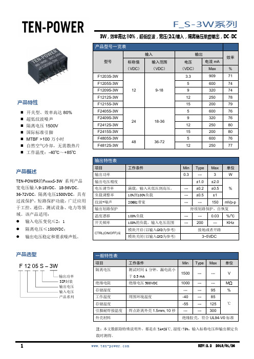
开关型、效率高达 80% 超低纹波噪声 隔离电压 1500V 国际标准引脚 MTBF >100 万小时 自然空气冷却,无需散热片 工作温度:-40℃~+85℃
产品概述
TEN-POWER的FxxxxS-3W 系列产品 宽电压输入9-18VDC,18-36VDC, 36-72VDC,隔离电压1500VDC,具有 过流保护,短路保护功能,广泛应用 于工控、通信、测试设备、电力等领 域。该产品适用: 输入电压变化≤2:1 隔离电压≤1500VDC; 输出电压稳定和要求噪声低。
输出特性表
项目 输出功率 输出电压精度 电压调节率 负载调整率 纹波+噪声 输出短路保护 温度漂移 开关频率
CTRL(ON/OFF)端
工作条件
满载,输入从低压到高压。 10%到100%负载 20MHz带宽
100%负载 100%的负载,输入电压范围 模块开启(以输入GND为参考) 模块关闭(以输入GND为参考)
REV:2.2 2013/01/26
3. 产品降额工作曲线 如右图所示。
4. 此产品不能并联使用,不支持热拔插
REV:2.2 2013/01/26
2
机械尺寸 & 引脚功能
11.10 [0.437]
4.0[0.160] 印字面
正视图 22.0[0.866]
F_S-3W系列
3W,效率高达 80%,超低纹波,宽压(2:1)输入,隔离稳压单路输出,DC-DC
3W,效率高达 80%,超低纹波,宽压(2:1)输入,隔离稳压单路输出,DC-DC
使用注意 & 典型应用
1. 最优输出负载要求 为了确保该模块能够高效可靠的工作,建议输出负载范围在50%-90%之间,这样可以获得最综合的性能:较高的效率、较低
隔离耐压3000VAC与3000VDC是否等效

可能很多朋友都遇到过这样的情况,耐压检测时打DC电压能通过,而打AC电压就出现报警或产品损坏。
其中的区别在哪里?隔离耐压3000VDC与3000VAC能等效吗?无论AC还是DC,3000V都是指有效值,3000VAC的幅值电压有4242V,那肯定有朋友会再问,那隔离耐压3000VAC与4242VDC能等效吗?答案也是不能的,原因如下:1、对于隔离模块,输入输出之间是存在隔离电容(这个电容等效于变压器原副边之间的耦合电容、PCB板原副边的耦合电容、光耦原副边的等效电容、以及模块内部原副边地之间可能外加的Y电容,这4个方面之和),大家都知道,对于直流信号,电容的阻抗无限大,而对于固定频率的交流信号,这个电容会等效于某一个固定的阻抗,因此隔离电容的大小对于直流信号没有太大的影响,而对于交流信号就会有较大的影响,表现在漏电流会变大,或者直接超标,系统报警。
2、AC与DC的另一个区别在于频率会影响绝缘介质的介电常数,频率会导致绝缘介质的介电常数降低,通常介电常数越高,绝缘能力越强。
举个例子,对于某个半成品的实验,10000VDC能通过检测,6000VAC不能通过检测,原因在于变压器原副边的空气有被电离,拉弧的现象。
那既然不能等效,是否可以把我们电源模块(尤其是我们的DC-DC模块)的AC耐压也做高呢?答案当然是肯定的,可以从以下3个方面着手:1、根据耐压等级及漏电流的要求计算出最低的隔离电容要求。
降低隔离电容可以从上面提及的4个方面着手。
2、根据耐压等级及隔离电容的要求,设计好合适的变压器,选择合适的光耦,PCB布局时原副边留好合适的距离。
3、根据耐压等级的要求,选择介电常数较大的灌封料,塑封料或者包封料,并确保内部没有气泡。
并评估50-60Hz的AC频率对介电常数的影响。
DC DC转换器 URB_MT-3WR3系列

3W,Ultra wide input isolated®ulated singleoutput DC/DC converterCB Patent Protection RoHSFEATURES●Ultra wide input voltage rang (4:1)●High efficiency up to 84%●No-load power consumption as low as 0.10W ●Isolation voltage:1.5K VDC●Input Under-voltage Protection ,outputshort-circuit protection ,over-current protection ●Operating temperature range:-40℃to +85℃●International standard pin-out●IEC60950,UL60950,EN60950approvalURB_MT-3WR3series products are of 3W output power,extremely wide range of voltage input of 9-36VDC,18-75VDC,isolation voltage of 1500VDC,Input Under-voltage Protection,output short circuit protection,over-current protection,these products are widely used in fields such as industrial control,electric power,instruments and communication.Selection GuideCertificationPart No.Input Voltage (VDC)OutputEfficiency ②(%,Min./Typ.)@Full LoadMax.Capacitive Load(µF)Nominal (Range)Max.①Output Voltage (VDC)Output Current (mA)(Max./Min.)--URB2403MT-3WR324(9-36)403.3728/073/752200UL /CE/CBURB2405MT-3WR35600/078/802200--URB2409MT-3WR39333/078/801000UL/CE/CBURB2412MT-3WR312250/080/82680URB2415MT-3WR315200/081/83470URB2424MT-3WR324125/080/82100CEURB4803MT-3WR348(18-75)803.3728/073/752200URB4805MT-3WR35600/077/792200URB4812MT-3WR312250/080/82680URB4815MT-3WR315200/082/84470URB4824MT-3WR324125/080/82100Notes:①Exceeding the maximum input voltage may cause permanent damage ;②The efficiency value is measured in the input nominal voltage and output rated load.Input SpecificationsItemOperating Conditions Min.Typ.Max.UnitInput Current (full load /no-load)24VDC input series nominal input voltage3.3V Output --134/4138/7mA Others --154/4161/748VDC input series nominal input voltage3.3V Output --67/469/7Others--77/482/7Reflected Ripple Current Nominal 24VDC input series --120--Nominal 48VDC input series --60--Surge Voltage (1sec.max.)Nominal 24VDC input series -0.7--50VDC Nominal 48VDC input series -0.7--100Starting VoltageNominal 24VDC input series ----9Nominal 48VDC input series ----18Input under-voltage protection Nominal 24VDC input series 5.5 6.5--Nominal 48VDC input series1315.5--Starting Time Nominal input voltage &constant resistance load--10--ms Input FilterC filterCtr l*Module turn-onCtrl pin floating or connected to TTL highlevel(3.5-12VDC)Module turn-offCtrl pin connected to GND or low level(0-1.2VDC)Input current when switched off--610mAHot PlugUnavailableNote:*The voltage of Ctrl pin is relative to input pin GND.Output SpecificationsItemOperating ConditionsMin.Typ.Max.UnitOutput Voltage Accuracy --±1±3%Line Regulation Full load,the input voltage is from low voltage to high voltage --±0.2±0.5Load Regulation 0%-100%load--±0.5±1Transient Recovery Time 25%load step change,nominal input voltage --300500µs Transient Response Deviation --±3±5%Temperature Coefficient Full load----±0.03%/℃Ripple &Noise*20MHz bandwidth ,5%-100%load --30120mV p-p Over-current Protection Input voltage range --150250%Io Short circuit ProtectionHiccup protectionNote:*Ripple and noise are measured by “parallel cable”method,please see DC-DC Converter Application Notes for specific operation.0%-5%load ripple&Noise is no more than 5%Vo.General SpecificationsItemOperating ConditionsMin.Typ.Max.Unit Insulation Voltage Input-output,with the test time of 1minute and the leak current lower than 1mA 1500----VDC Insulation Resistance Input-output,insulation voltage 500VDC 1000----M ΩIsolation Capacitance Input-output,100KHz/0.1V --1000--pFOperating Temperature see Fig.1-40--+85℃Storage Temperature -55--+125Casing Temperature Rise Ta=25℃,nominal input voltage,full load output --+40--Pin Welding Resistance Temperature Welding spot is 1.5mm away from the casing,10seconds ----+300Storage HumidityNon-condensing 5--95%RH Reflow Soldering Temperature Peak temp.≤245℃,maximum duration time ≤60s at 217℃.For actual application,please refer to IPC/JEDEC J-STD-020D.1.Vibration10-55Hz,10G,30Min.along X,Y and ZSwitching Frequency*PWM Mode--350--KHz MTBFMIL-HDBK-217F@25℃1000----K hoursNote:*This series of products using lower frequency technology,the switching frequency value is the test value in full load,when the load is reduced to 50%or less,the switching frequency decreases with decreasing load.Physical SpecificationsCasing Material Black flame-retardant heat-proof plastic Dimensions 19.20*18.10*10.16mm Weight3.5g(Typ.)Cooling MethodFree air convectionEMC SpecificationsEMICECISPR22/EN55022CLASS B (see Fig.3-②for recommended circuit)RE CISPR22/EN55022CLASS B (see Fig.3-②for recommended circuit)EMSESD IEC/EN61000-4-2Contact ±4KV perf.Criteria B RS IEC/EN61000-4-310V/mperf.Criteria A EFT IEC/EN61000-4-4±2KV (see Fig.3-①for recommended circuit)perf.Criteria B Surge IEC/EN61000-4-5line to line ±2KV (see Fig.3-①for recommended circuit)perf.Criteria B CSIEC/EN61000-4-63Vr.m.sperf.Criteria A Immunities of voltage dip,drop and short interruptionIEC/EN61000-4-290%,70%perf.Criteria BProduct Characteristic CurveOperating Temperature()℃Temperature Derating CurveO u t p u t P o w e r P e r c e n t a g e (%)-400407185120806010012040200Safe Operating AreaFig.1Design Reference1.Typical applicationAll the DC/DC converters of this series are tested according to the recommended circuit (see Fig.2)before delivery.If it is required to further reduce input and output ripple,properly increase the input &output of additional capacitors Cin and Cout or select capacitors of low equivalent impedance provided that the capacitance is no larger than the max.capacitive load of the product.VinGND+Vo0VDCCinDC CoutFig.2Vn Cin Cout 24VDC 100µF 10µF 48VDC10µF-47µF10µF2.EMC solution-recommended circuitVi nGND+Vo0VDC/DCLOADC2LDM1②MOVFUSE①C1CY1C3C0+Vi nGNDFig.3Notes:Part ①in the Fig.3is used for EMS test and part ②for EMI filtering;selected based on needs.Parameter descriptionModel Vin:24V Vin:48V FUSE Choose according to actual input currentMOV S20K30S14K60C0680µF/50V 680µF/100V C1,C2 4.7µF/50V4.7µF/100VC3Refer to the Cout in Fig.2LDM112µH CY11nF/2KV3.It is not allowed to connect modules output in parallel to enlarge the power4.For more information about Mornsun EMC Filter products,please visit todownload the Selection Guide of EMC FilterDimensions and Recommended LayoutNC:Pin to be isolated from circuitryNotes:1.Packing information please refer to Product Packing Information which can be downloaded from .TubePacking Bag Number:58010114,Reel Packing Bag Number:58010115;2.The max.capacitive load should be tested within the input voltage range and under full load conditions;3.If the product needs to be cleaned after welding,please wait to completely dried before electrical use it;4.Unless otherwise specified,parameters in this datasheet were measured under the conditions of Ta=25℃,humidity<75%RH with nominalinput voltage and rated output load;5.All index testing methods in this datasheet are based on our Company’s corporate standards;6.We can provide product customization service,please directly contact our technicians for specific information;7.Specifications of this product are subject to changes without prior notice.Mornsun Guangzhou Science&Technology Co.,Ltd.Address:No.5,Kehui St.1,Kehui Development Center,Science Ave.,Guangzhou Science City,Luogang District,Guangzhou,P.R.China Tel:86-20-38601850-8801Fax:86-20-38601272E-mail:***************。
- 1、下载文档前请自行甄别文档内容的完整性,平台不提供额外的编辑、内容补充、找答案等附加服务。
- 2、"仅部分预览"的文档,不可在线预览部分如存在完整性等问题,可反馈申请退款(可完整预览的文档不适用该条件!)。
- 3、如文档侵犯您的权益,请联系客服反馈,我们会尽快为您处理(人工客服工作时间:9:00-18:30)。
12 (9-18)
9
33
333
82
12
25
250
83
15
20
200
83
1000 680 470
ZY1224WRFCS-3W
24
12
125
83
330
ZY2405WRFCS-3W
5
60
600
79
2200
ZY2412WRFCS-3W
24
12
25
250
82
680
ZY2415WRFCS-3W
(18-36)
15
R = VC - VD -1 −150 IC
4. 负载要求
为了确保模块能够高效可靠的运行,建议输出负载应在额定负载的 10%到 100%之间,不建议长期在低于 10%负 载的情况下运行,否则部分产品性能不能符合本手册性能指标。
5. 注意事项
不支持热插拔功能。
广州致远电子股份有限公司
©2014 Guangzhou ZHIYUAN Electronics Stock CO., LTD.
第4页 共4页
0
40
71 85
120
环境温度(℃)
环境温度降额曲线图
效率(%) 效率(%)
100
ZY2405WRFCS-3W
ZY2415WRFCS-3W
90
80
70
60
2405
50
2415
40
30
20
10
0
10 20 30 40 50 60 70 80 90 100
负载百分比(%)
效率与负载关系曲线图
外观与包装尺寸
C1(μF) 100
10~22
Lin(μH) 4.7~120
C2、CS(μF) 100
3. Ctrl 脚
悬空或高阻时,模块正常输出;接高电平(相对于输入地)时,模块关断。注意:一般输入 Ctrl 脚电流在 5 到 10mA 为宜,电流超过其最大值(一般为 20mA)会造成模块永久性损坏。电阻 R 取值公式:
NC:不能与任何外部电路连接
12.20(0.480)
吸塑管
14.50(0.570) 20.60(0.811)
0.80 (0.031)
6.30(0.248) 注: 尺寸单位:mm(inch) 未标注之公差:±0.50(±0.020) L=282(11.102),管装数量: 11pcs 外箱规格:304×120×40mm 外箱包装数量:198pcs
最小值
典型值
最大值
单位
3000
--
--
VDC
1
--
--
GΩ
--
45
--
pF
--
250
--
kHz
1000
--
--
k hours
22.20×9.20×12.20
mm
黑色阻燃塑胶外壳,符合 UL94-V0 标准
环境特性
参数 工作温度 存储温度 外壳温升 存储湿度 冷却方式
条件 湿度≤ 95% 湿度≤ 95%
22.20(0.874)
前视图
16.30(0.642) 12.20(0.480)
0.50(0.020)
9.20(0.362)
底视图
123
5678
1.30 (0.051)
2.10(0.083)
2.54 (0.100)
PCB丝印图(俯视图)
Ø1.00 (Ø0.039)
123
5678
注: 尺寸单位:mm(inch) 未标注之公差:±0.50(±0.020) 栅格距离:2.54×2.54mm
条件 12VDC 输入系列 24VDC 输入系列 焊点距离外壳 1.5mm,10 秒
ZY_WRFCS-3W
宽压输入隔离稳压单路输出系列
最小值 -0.7 -0.7 --
典型值 ----
最大值 25 50 300
单位 VDC
℃
输入特性
参数 空载/满载输入电流
输入滤波器 Ctrl
条件 标称输入电压,12VDC 输入系列 标称输入电压,24VDC 输入系列
广州致远电子股份有限公司
©2014 Guangzhou ZHIYUAN Electronics Stock CO., LTD.
第3页 共4页
电路设计与应用
产品数据手册
Data Sheet
ZY_WRFCS-3W
宽压输入隔离稳压单路输出系列
1. 应用电路
Vin GND
Vc
Lin
2
C1 1
D1 Ic
R3
广州致远电子股份有限公司
©2014 Guangzhou ZHIYUAN Electronics Stock CO., LTD.
第2页 共4页
产品数据手册
Data Sheet
产品特性曲线
输出功率百分比(%)
ZY_WRFCS-3W
宽压输入隔离稳压单路输出系列
120 100
80 60 40 20 0
-40
产品数据手册 ZY_WRFCS-3W
Data Sheet
宽压输入隔离稳压单路输出系列
V1.10 Date: 2014/11/25
产品系列————————————————
产品系列 ZY_WRFCS-3W
温度范围
隔离耐压
-40℃~+85℃ 3000VDC
封装 SIP
产品特性—————————————————
Ta=25℃ 无凝结
最小值 -40 -55 ---
典型值
最大值
--
+85
--
+125
20
35
--
95
自然空冷
单位 ℃ %
注:(1)输入电压不能超过所规定范围值,否则可能会造成永久性不可恢复的损坏。 (2)如没有特殊说明,本手册中的参数都是在 25℃,湿度小于 75%,输入标称电压和输出纯电阻模式下测得。 (3)输出纹波噪声采用靠接测试法。
模块开启 模块关断
最小值
典型值
最大值
单位
--
20/310
--
mA
--
10/155
--
电容滤波
Ctrl 脚悬空或者高阻 接高电平(相对于输入地),使流入 Ctrl 脚电流为 5~10mA
输出特性
参数 线性调整率 负载调整率 输出电压精度 温度漂移系数 输出纹波噪声 输出短路保护
条件 满载,输入电压从低电压到高电压 标称输入电压,负载从 10%—100%变化
ZY2405WRFCS-3W
ZY2415WRFCS-3W
85
83
81
79
77
2405
75
73
2415
71
69
67
65
18 20 22 24 26 28 30 32 34 36
输入电压(VDC)
效率与输入电压关系曲线图
引脚 1 2 3 5 6 7 8
功能 GND Vin Ctrl NC +Vo 0V CC
效率高达 83%; 隔离电压:3000VDC; 可持续短路,自恢复; 外壳及灌封材料符合 UL94-V0 标准; 无需外加散热器; 封装与国际、国内同类型产品 PIN 对 PIN 兼容。
产品应用————————————————
运算放大器电源; 继电器驱动电路; 一般低频模拟电路; 医学、手持、便携仪表; 纯数字电路、模拟前端隔离电路; ……
6
8 CS
7
+VOUT C2
0V
图 1 应用电路图
2. 滤波电容
外加滤波电容的选取请参考表 1 中的数值,选择电容依据 ESR 小于 1Ω(在频率为 100kHz),建议选用陶瓷或电 解电容,不建议选用钽电容。输入及输出滤波电容值不能选择太大,否则很可能会造成启动问题。
表 1 推荐外接电容值
Vin(VDC) 12 24
20
200
82
470
ZY2424WRFCS-3W
24
12
125
82
330
广州致远电子股份有限公司
©2014 Guangzhou ZHIYUAN Electronics Stock CO., LTD.
第1页 共4页
产品数据手册
Data Sheet
极限特性
参数 输入冲击电压(1)(1s,max)
引脚焊接温度
产品型号———————————————————————————————————————
产品型号 ZY1205WRFCS-3W
输入标称电压 (电压范围) (VDC)
标称电压 (VDC)
5
输出 最小电流
(mA) 60
最大电流 (mA)
600
满载效率 (%,Typ)
80
最大容性负载 (μF)
2200
ZY1209WRFCS-3W ZY1212WRFCS-3W ZY1215WRFCS-3W
负载从 10%—100%变化 100%负载 20MHz 带宽
最小值 ------
典型值
最大值
±0.2
±0.5
±0.5
±0.75
±1
±3
--
±0.03
50
100
可持续短路,自恢复
单位
%
%/℃ mVp-p
一般特性
参数 隔离电压 绝缘电阻 隔离电容 开关频率 平均无故障时间 封装尺寸 外壳材料
条件 时间 1 分钟 绝缘电压 500VDC 100kHz,0.1V 标称输入电压,100%负载 MIL-HDBK-217F@25℃