IAR Embedded Workbench KickStart Release Notes
基于IAR-Embedded-Workbench-for-ARM-7.20的STM32F302-Nucleo板的开发环境的工程建立
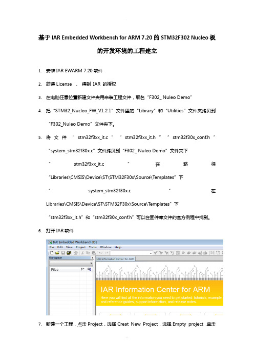
基于IAR Embedded Workbench for ARM 7.20的STM32F302 Nucleo板的开发环境的工程建立1.安装IAR EWARM 7.20软件2.获得License , 得到IAR 的授权3.在电脑任意位置新建文件夹用来装工程文件,取名“F302_ Nuleo Demo”4.把“STM32_Nucleo_FW_V1.2.1”文件里的“Library”和“Utilities”文件夹拷贝到“F302_Nuleo Demo”文件夹下。
5.将文件“stm32f3xx_it.c”“stm32f3xx_it.h”“stm32f30x_conf.h”“system_stm32f30x.c”文件拷贝到“F302_ Nuleo Demo”文件夹下“stm32f3xx_it.c”在路径“Libraries\CMSIS\Device\ST\STM32F30x\Source\Templates”下“system_stm32f30x.c”在Libraries\CMSIS\Device\ST\STM32F30x\Source\T emplates”下“stm32f3xx_it.h”和“stm32f30x_conf.h”可以在固件库文件的官方例程中找到。
6.打开IAR软件7.新建一个工程,点击Project,选择Creat New Project,选择Empty project ,单击OK保存到刚刚新建的F302_Nucleo Demo文件夹下,文件命名为“F302_Nucleo Demo”8. A.建立好空的工程了,下面需要做的事情就是将必须的文件添加进去,对着对着Workspace下面的Files文件树里面的F302_Nucleo Demo右键,选择”add”“add group”,添加”CMSISI, EWARM , LIBRARY , User”这几个group,如下图:B.新建文件夹“main.c”、“main.h”,并将这两个文件保存到文件夹“F302_NucleoDemo”下,编辑文件“main.h”,在文件中添加如下代码段:#ifndef __MAIN_H#define __MAIN_H#include "stm32f3xx_nucleo.h"#endifC.然后分别在每个文件夹下添加需要的文件,需添加的文件如下:9. A.鼠标放在工程上单击右键,选择“option”,进行相关的设置:首先在General Option里面的Target 选择core为Cortex-M0,选择Device为ST STM32F302x8B.然后在C/C++ Compiler里面的Optimization里选择Level为High。
Atme AVR IAR Embedded Workbench IDE 说明书
AVR® IAR Embedded Workbench® IDE用户手册基于Atmel® 公司AVR® 微处理器目录第一部分产品介绍 (1)1.1产品介绍 (1)1.1.1嵌入式IAR Embedded Workbench IDE (1)1.1.2 IAR C-SPY 调试器 (3)1.1.3 IAR C-SPY 调试器系统 (5)1.1.4 IAR C/C++编译器 (8)1.1.5 IAR汇编器 (9)1.1.6 IAR XLINK连接器 (9)1.1.7 IAR XAR Library Builder库创建器和IAR XLIB Librarian库管理器 (10)1.2已安装文件 (11)1.2.1目录结构 (11)1.2.2文件类型 (14)1.2.3文档 (16)第二部分教程 (18)2.1创建一个应用工程 (18)2.1.1创建一个新工程 (18)2.1.2应用程序编译和连接 (23)2.2使用IAR C-SPYDebugger进行调试 (28)程序调试 (28)2.3 C与汇编混合模式 (36)2.3.1检查调用规则 (36)2.3.2在工程中添加一个汇编模块 (37)2.4使用C++ (38)创建一个C++应用程序 (39)2.5模拟一个中断 (41)2.5.1加入一个中断句柄 (42)2.5.2创建仿真环境 (43)2.5.3中断仿真 (48)2.5.4中断和断点中宏的使用 (49)2.6使用库模块 (50)使用库 (50)第一部分产品介绍AVR® IAR Embedded Workbench® IDE用户手册的这部分包括以下章节:z产品介绍z已安装文件1.1产品介绍嵌入式IAR Embedded Workbench®是一个非常有效的集成开发环境(IDE),它使用户充分有效地开发并管理嵌入式应用工程。
作为一个开发平台,它具备任何在用户每天的工作地方所想要的特性。
常见ARM编译器简介
常见ARM编译器简介ARM应用软件的开发工具根据功能的不同,分别有编译软件、汇编软件、链接软件、调试软件、嵌入式实时操作系统、函数库、评估板、JTAG仿真器、在线仿真器等,目前世界上约有四十多家公司提供以上不同类别的产品。
用户选用ARM处理器开发嵌入式系统时,选择合适的开发工具可以加快开发进度,节省开发成本。
因此一套含有编辑软件、编译软件、汇编软件、链接软件、调试软件、工程管理及函数库的集成开发环境(IDE)一般来说是必不可少的,至于嵌入式实时操作系统、评估板等其他开发工具则可以根据应用软件规模和开发计划选用。
使用集成开发环境开发基于ARM的应用软件,包括编辑、编译、汇编、链接等工作全部在PC机上即可完成,调试工作则需要配合其他的模块或产品方可完成。
(一)SDTARM SDT的英文全称是ARM Software Development Kit,是ARM公司(为方便用户在ARM芯片上进行应用软件开发而推出的一整套集成开发工具。
ARM SDT经过ARM公司逐年的维护和更新,目前的最新版本是2.5.2,但从版本2.5.1开始,ARM公司宣布推出一套新的集成开发工具ARM ADS1.0,取ARM SDT而代之,今后将不会再看到ARM SDT的新版本。
ARM SDT由于价格适中,同时经过长期的推广和普及,目前拥有最广泛的ARM软件开发用户群体,也被相当多的ARM公司的第三方开发工具合作伙伴集成在自己的产品中,比如美国EPI公司的JEENI仿真器。
ARM SDT(以下关于ARM SDT的描述均是以版本 2.50为对象)可在Windows95、98、NT以及Solaris2.5/2.6、HP-UX10上运行,支持最高到ARM9(含ARM9)的所有ARM处理器芯片的开发,包括StrongARM。
ARM SDT包括一套完整的应用软件开发工具:*armcc ARM的C编译器,具有优化功能,兼容于ANSI C。
*tcc THUMB的C编译器,同样具有优化功能,兼容于ANSI C。
IAR Embedded Workbench for ARM 8.20安装使用图文教程

3.IAR Embedded Workbench for ARM 8.20注册
执行完后,再回到IAR License Manager for arm 8.20.1 界面 执行激活。如图
。
谢谢!Leabharlann 安装完成!手动破解注册,分享给大家,希望真正能帮助到有需求的朋友!
IAR Embedded Workbench for ARM 8.20安装注册图文教程安装步骤: 1.IAR Embedded Workbench for ARM 8.20下载 2.IAR Embedded Workbench for ARM 8.20安装 3.IAR Embedded Workbench for ARM 8.20注册、激活
IAR Embedded Workbench for ARM 8.20安装使用图文教 程
DrMeng 2017.12.17
IAR Embedded Workbench for ARM 8.20安装使用图文教程
导读:IAR Embedded Workbench for ARM 8.20(简称 IAR for 8.20)是一款强大的嵌入式开 发的软件并且含有IAR Embedded Workbench注册机 ,主要用于单片机开发是一套高度精密且 使用方便的嵌入式应用编程开发工具,那么要怎么破解安装呢?笔者这里重点给大家讲解如何
成都无线龙通讯 IAR Embedded Workbench叉编译器和调试器 说明书
IAR安装与使用IAR Embedded Workbench(简称EW)的C/C++交叉编译器和调试器是今天世界最完整的和最容易使用专业嵌入式应用开发工具。
EW对不同的微处理器提供一样直观用户界面。
EW今天已经支持35种以上的8位/16位32位ARM的微处理器结构。
EW包括:嵌入式C/C++优化编译器,汇编器,连接定位器,库管理员,编辑器,项目管理器和C-SPY调试器中。
使用IAR的编译器最优化最紧凑的代码,节省硬件资源,最大限度地降低产品成本,提高产品竞争力。
EWARM是IAR目前发展很快的产品,EWARM已经支持ARM7/9/10/11XSCALE,并且在同类产品中具有明显价格优势。
其编译器可以对一些SOC芯片进行专门的优化. 如Atmel,TI,ST,Philips。
除了EWARM标准版外,IAR公司还提供EWARM BL(256K)的版本,方便了不同层次客户的需求。
IAR System是嵌入式领域唯一能够提供这种解决方案的公司。
EW支持35种以上的8位/16位/32位的微处理器结构。
IAR Embedded Workbench集成的编译器主要产品特征:•高效PROMable代码•完全标准C兼容•内建对应芯片的程序速度和大小优化器•目标特性扩充•版本控制和扩展工具支持良好•便捷的中断处理和模拟•瓶颈性能分析•高效浮点支持•内存模式选择•工程中相对路径支持我们为什么要放弃使其他各种用免费的开发工具,而选择需要支付费用来购买IAR Systems 的开发工具?主要包括一下几点原因:由于IAR公司在微处理器C/C++编译器设计方面的丰富经验,目前没有任何一家公司的产品可以接近IAR公司针对8 位、16 位、32 位处理器生产的30多种不同C/C++编译器的水平。
经过反复实验证明,IAR Systems 的C/C++编译器可以生成高效可靠的可执行代码,并且应用程序规模越大,效果明显。
与其他的工具开发厂商相比,系统同时使用全局和针对具体芯片的优化技术。
简述iar工程的相关配置流程
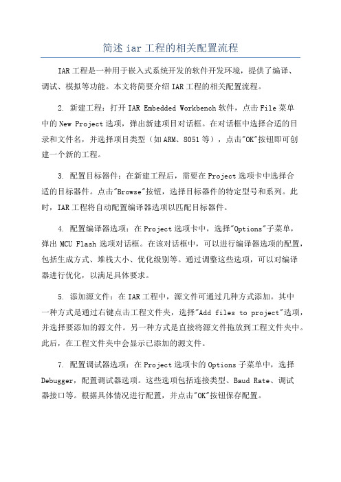
简述iar工程的相关配置流程IAR工程是一种用于嵌入式系统开发的软件开发环境,提供了编译、调试、模拟等功能。
本文将简要介绍IAR工程的相关配置流程。
2. 新建工程:打开IAR Embedded Workbench软件,点击File菜单中的New Project选项,弹出新建项目对话框。
在对话框中选择合适的目录和文件名,并选择项目类型(如ARM、8051等),点击"OK"按钮即可创建一个新的工程。
3. 配置目标器件:在新建工程后,需要在Project选项卡中选择合适的目标器件。
点击"Browse"按钮,选择目标器件的特定型号和系列。
此时,IAR工程将自动配置编译器选项以匹配目标器件。
4. 配置编译器选项:在Project选项卡中,选择"Options"子菜单,弹出MCU Flash选项对话框。
在该对话框中,可以进行编译器选项的配置,包括生成方式、堆栈大小、优化级别等。
通过调整这些选项,可以对编译器进行优化,以满足具体要求。
5. 添加源文件:在IAR工程中,源文件可通过几种方式添加。
其中一种方式是通过右键点击工程文件夹,选择"Add files to project"选项,并选择要添加的源文件。
另一种方式是直接将源文件拖放到工程文件夹中。
此后,在工程文件夹中会显示已添加的源文件。
7. 配置调试器选项:在Project选项卡的Options子菜单中,选择Debugger,配置调试器选项。
这些选项包括连接类型、Baud Rate、调试器接口等。
根据具体情况进行配置,并点击"OK"按钮保存配置。
8. 编译工程:在进行配置之后,可以点击工具栏上的"Build"按钮进行编译。
编译器将从指定的目标文件夹中读取源文件,进行编译和链接操作,生成可执行的目标文件。
9.调试工程:通过调试器,可以在实际硬件上运行和调试目标代码。
IAR Embeded Workbench的C变量段分配
IAR Embeded Workbench的C变量段分配 -- Cortex-M3(LM3S618)开发环境为IAR Embeded Workbench IDE启动代码startup.c如下://******************************************************************* **********//// startup.c - Boot code for Stellaris.//// Copyright (c) 2005-2008 Luminary Micro, Inc. All rights reserved. //// Software License Agreement//// Luminary Micro, Inc. (LMI) is supplying this software for use solely and// exclusively on LMI's microcontroller products.//// The software is owned by LMI and/or its suppliers, and is protected under// applicable copyright laws. All rights are reserved. You may not combine // this software with "viral" open-source software in order to form a larger// program. Any use in violation of the foregoing restrictions may subject // the user to criminal sanctions under applicable laws, as well as to civil// liability for the breach of the terms and conditions of this license. //// THIS SOFTWARE IS PROVIDED "AS IS". NO WARRANTIES, WHETHER EXPRESS, IMPLIED// OR STATUTORY, INCLUDING, BUT NOT LIMITED TO, IMPLIED WARRANTIES OF // MERCHANTABILITY AND FITNESS FOR A PARTICULAR PURPOSE APPLY TO THIS SOFTWARE.// LMI SHALL NOT, IN ANY CIRCUMSTANCES, BE LIABLE FOR SPECIAL, INCIDENTAL, OR// CONSEQUENTIAL DAMAGES, FOR ANY REASON WHATSOEVER.//// This is part of revision 2752 of the Stellaris Peripheral Driver Library. ////******************************************************************* **********//******************************************************************* **********//// Enable the IAR extensions for this source file.////******************************************************************* **********#pragma language=extended//******************************************************************* **********//// Forward declaration of the default fault handlers.////******************************************************************* **********void ResetISR(void);static void NmiSR(void);static void FaultISR(void);static void IntDefaultHandler(void);//******************************************************************* **********//// The entry point for the application.////******************************************************************* **********extern int main(void);//******************************************************************* **********//// Reserve space for the system stack.////******************************************************************* **********#ifndef STACK_SIZE#define STACK_SIZE 256#endifstatic unsigned long pulStack[STACK_SIZE];//******************************************************************* **********//// A union that describes the entries of the vector table. The union is needed// since the first entry is the stack pointer and the remainder are function// pointers.////******************************************************************* **********typedef union{void (*pfnHandler)(void);unsigned long ulPtr;}uVectorEntry;//******************************************************************* **********//// The minimal vector table for a Cortex M3. Note that the proper constructs// must be placed on this to ensure that it ends up at physical address // 0x0000.0000.////******************************************************************* **********__root const uVectorEntry g_pfnVectors[] @ "INTVEC" ={{ .ulPtr = (unsigned long)pulStack + sizeof(pulStack) },// The initial stack pointerResetISR, // The reset handlerNmiSR, // The NMI handlerFaultISR, // The hard fault handler IntDefaultHandler, // The MPU fault handler IntDefaultHandler, // The bus fault handler IntDefaultHandler, // The usage fault handler 0, // Reserved0, // Reserved0, // Reserved0, // ReservedIntDefaultHandler, // SVCall handlerIntDefaultHandler, // Debug monitor handler 0, // ReservedIntDefaultHandler, // The PendSV handlerIntDefaultHandler, // The SysTick handlerIntDefaultHandler, // GPIO Port AIntDefaultHandler, // GPIO Port BIntDefaultHandler, // GPIO Port CIntDefaultHandler, // GPIO Port DIntDefaultHandler, // GPIO Port EIntDefaultHandler, // UART0 Rx and TxIntDefaultHandler, // UART1 Rx and TxIntDefaultHandler, // SSI Rx and TxIntDefaultHandler, // I2C Master and SlaveIntDefaultHandler, // PWM FaultIntDefaultHandler, // PWM Generator 0IntDefaultHandler, // PWM Generator 1IntDefaultHandler, // PWM Generator 2IntDefaultHandler, // Quadrature EncoderIntDefaultHandler, // ADC Sequence 0IntDefaultHandler, // ADC Sequence 1IntDefaultHandler, // ADC Sequence 2IntDefaultHandler, // ADC Sequence 3IntDefaultHandler, // Watchdog timerIntDefaultHandler, // Timer 0 subtimer AIntDefaultHandler, // Timer 0 subtimer BIntDefaultHandler, // Timer 1 subtimer AIntDefaultHandler, // Timer 1 subtimer BIntDefaultHandler, // Timer 2 subtimer AIntDefaultHandler, // Timer 2 subtimer BIntDefaultHandler, // Analog Comparator 0IntDefaultHandler, // Analog Comparator 1IntDefaultHandler, // Analog Comparator 2IntDefaultHandler, // System Control (PLL, OSC, BO)IntDefaultHandler, // FLASH ControlIntDefaultHandler, // GPIO Port FIntDefaultHandler, // GPIO Port GIntDefaultHandler, // GPIO Port HIntDefaultHandler, // UART2 Rx and TxIntDefaultHandler, // SSI1 Rx and TxIntDefaultHandler, // Timer 3 subtimer AIntDefaultHandler, // Timer 3 subtimer BIntDefaultHandler, // I2C1 Master and Slave IntDefaultHandler, // Quadrature Encoder 1IntDefaultHandler, // CAN0IntDefaultHandler, // CAN1IntDefaultHandler, // CAN2IntDefaultHandler, // EthernetIntDefaultHandler, // HibernateIntDefaultHandler, // USB0IntDefaultHandler, // PWM Generator 3IntDefaultHandler, // uDMA Software Transfer IntDefaultHandler // uDMA Error};//******************************************************************* **********//// The following are constructs created by the linker, indicating where the// the "data" and "bss" segments reside in memory. The initializers for the// for the "data" segment resides immediately following the "text" segment. ////******************************************************************* **********#pragma segment="DATA_ID"#pragma segment="DATA_I"#pragma segment="DATA_Z"//******************************************************************* **********//// This is the code that gets called when the processor first starts execution// following a reset event. Only the absolutely necessary set is performed, // after which the application supplied main() routine is called. Any fancy// actions (such as making decisions based on the reset cause register, and// resetting the bits in that register) are left solely in the hands of the// application.////******************************************************************* **********voidResetISR(void){unsigned long *pulSrc, *pulDest, *pulEnd;//// Copy the data segment initializers from flash to SRAM.//pulSrc = __segment_begin("DATA_ID");pulDest = __segment_begin("DATA_I");pulEnd = __segment_end("DATA_I");while(pulDest < pulEnd){*pulDest++ = *pulSrc++;}//// Zero fill the bss segment.//pulDest = __segment_begin("DATA_Z");pulEnd = __segment_end("DATA_Z");while(pulDest < pulEnd){*pulDest++ = 0;}//// Call the application's entry point.//main();}//******************************************************************* **********//// This is the code that gets called when the processor receives a NMI. This// simply enters an infinite loop, preserving the system state for examination// by a debugger.////******************************************************************* **********static voidNmiSR(void){//// Enter an infinite loop.//while(1){}}//******************************************************************* **********//// This is the code that gets called when the processor receives a fault // interrupt. This simply enters an infinite loop, preserving the system state// for examination by a debugger.////******************************************************************* **********static voidFaultISR(void){//// Enter an infinite loop.//while(1){}}//******************************************************************* **********//// This is the code that gets called when the processor receives an unexpected// interrupt. This simply enters an infinite loop, preserving the system state// for examination by a debugger.////******************************************************************* **********static voidIntDefaultHandler(void){//// Go into an infinite loop.//while(1){}}main.c源代码如下:#define MY_IAR_ICC //使用ICCARM编译器// 包含必要的头文件#include "my_lm3s618.h" //根据IAR提供的头文件iolm3s618.h和io_macros.h修改得到// 主函数(程序入口)int a[2];int b[2] = {10};__no_init int c;int d = 10;int main(void){int e[50] = {10};int f[100];}make后这些变量的段分配如下:变量所在段a[2] DATA_Zb[2] DATA_Ic DATA_Nd DATA_Ie[50] DATA_Zf[100] DATA_Z说明:1)DATA_Z 存储零初始化的静态和全局变量DATA_I 存储初始化的静态和全局变量DATA_N 存储由__no_init修饰的的静态和全局变量(关于各种类型段定义参考《ARM IAR C/C++ Compiler Reference Guide》P217)2)为什么e[50]和f[100]存储在DATA_Z中?e[50]和f[100]是在main.c中定义的局部变量,C编译器规定了局部变量从栈中分配空间。
IAR Embedded Workbench KickStart Release Notes
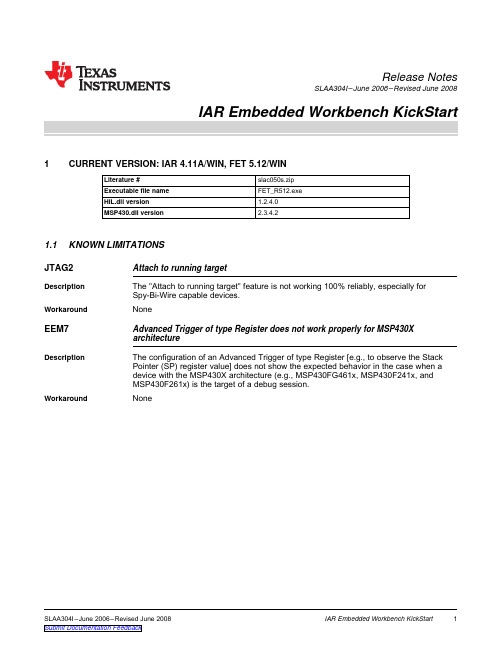
1CURRENT VERSION:IAR 4.11A/WIN,FET 5.12/WIN1.1KNOWN LIMITATIONSRelease NotesSLAA304I–June 2006–Revised June 2008Literature #slac050s.zip Executable file name FET_R512.exe HIL.dll version 1.2.4.0MSP430.dll version2.3.4.2JTAG2Attach to running targetDescription The "Attach to running target"feature is not working 100%reliably,especially for Spy-Bi-Wire capable devices.WorkaroundNoneEEM7Advanced Trigger of type Register does not work properly for MSP430X architectureDescriptionThe configuration of an Advanced Trigger of type Register [e.g.,to observe the Stack Pointer (SP)register value]does not show the expected behavior in the case when a device with the MSP430X architecture (e.g.,MSP430FG461x,MSP430F241x,and MSP430F261x)is the target of a debug session.WorkaroundNoneSLAA304I–June 2006–Revised June 2008IAR Embedded Workbench KickStart 1Submit Documentation Feedback2PRIOR VERSION:IAR 4.010E/WIN,FET 5.11/WIN2.1KNOWN LIMITATIONSPRIOR VERSION:IAR 4.010E/WIN,FET 5.11/WIN Literature #slac050r.zip Executable file name FET_R511.exe HIL.dll version 1.2.2.0MSP430.dll version2.3.3.0JTAG2Attach to running targetDescription The "Attach to running target"feature is not working 100%reliably,especially for Spy-Bi-Wire capable devices.WorkaroundNoneEEM7Advanced Trigger of type Register does not work properly for MSP430X architectureDescriptionThe configuration of an Advanced Trigger of type Register [e.g.,to observe the Stack Pointer (SP)register value]does not show the expected behavior in the case when a device with the MSP430X architecture (e.g.,MSP430FG461x,MSP430F241x,and MSP430F261x)is the target of a debug session.WorkaroundNoneCSPY1Integer values of C-type 'long'(32bit)are displayed incorrectly in Watch window for MSP430X architectureDescriptionThis affects 32-bit values that are held in two CPU registers;e.g.,a value of 0x00123456is stored in R14and R15.The lower word of the 32-bit value is stored as R14=0x3456,and the higher word is stored as R15=0x0012.The C-Spy Watch window shows a value of 0x12003456.This is a problem with the Watch window only–the program code produces the correct results.It is recommended not to change the dedicated 32-bit value via the Watch window,as this can cause unpredictable behavior.This limitation is only valid when a device with the MSP430X architecture is the target of a debug session.WorkaroundNoneIAR Embedded Workbench KickStart2SLAA304I–June 2006–Revised June 2008Submit Documentation Feedback3PRIOR VERSION:IAR 4.09A/WIN,FET 5.10/WIN3.1KNOWN LIMITATIONS PRIOR VERSION:IAR 4.09A/WIN,FET 5.10/WINLiterature #slac050q.zip Executable file name FET_R510.exe HIL.dll version 1.2.2.0MSP430.dll version2.3.1.0JTAG2Attach to running targetDescription The "Attach to running target"feature is not working 100%reliably,especially for Spy-Bi-Wire capable devices.WorkaroundNoneEEM7Advanced Trigger of type Register does not work properly for MSP430X architectureDescriptionThe configuration of an Advanced Trigger of type Register [e.g.,to observe the Stack Pointer (SP)register value]does not show the expected behavior in the case where a device with the MSP430X architecture (e.g.,MSP430FG461x,MSP430F241x,and MSP430F261x)is the target of a debug session.WorkaroundNoneIDE1Key bindings are deletedDescriptionIf this version of the IAR Embedded Workbench (4.09A/WIN)is installed in the same subdirectory where a previous version (e.g.,3.42A/WIN)is already installed,all key bindings [e.g.,debug hotkeys F5(Go),F10(Step Over),F11(Step Into)]are deleted in both versions.WorkaroundSelect in main menu Tools ->Options...->Key Bindings and push the 'Reset All'button in each IAR installation.CSPY1Integer values of C-type 'long'(32bit)are displayed incorrectly in Watch window for MSP430X architectureDescriptionThis affects 32-bit values that are held in two CPU registers;e.g.,a value of 0x00123456is stored in R14and R15.The lower word of the 32-bit value is stored as R14=0x3456,and the higher word is stored as R15=0x0012.The C-Spy Watch window shows a value of 0x12003456.This is a problem with the Watch window only–the program code produces the correct results.It is recommended not to change the dedicated 32-bit value via the Watch window,as this can cause unpredictable behavior.This limitation is only valid in the case where a device with the MSP430X architecture is the target of a debug session.WorkaroundNoneDEVICE3MSP430F2616and MSP430F2617devices are not correctly recognized by debuggerDescriptionWhen starting a debug session the Emulator shows a warning that "Chosen derivative (MSP430F2616)and actual hardware (MSP430F2619)do not match."for a project configured for MSP430F2616and "Chosen derivative (MSP430F2617)and actual hardware (MSP430F2618)do not match."for a project configured for MSP430F2617.WorkaroundMessage can be ignored.Click 'Yes'to continue download and start debug session.SLAA304I–June 2006–Revised June 2008IAR Embedded Workbench KickStart3Submit Documentation Feedback4PRIOR VERSION:IAR 3.42A/WIN,FET 4.63/WIN4.1KNOWN LIMITATIONSPRIOR VERSION:IAR 3.42A/WIN,FET 4.63/WIN Literature #slac050p.zip Executable file name FET_R463.exe HIL.dll version 1.2.2.0MSP430.dll version2.1.10.1JTAG2Attach to running targetDescription The "Attach to running target"feature is not working 100%reliably,especially for Spy-Bi-Wire capable devices.WorkaroundNoneEEM6Emulator Clock Control is not active by defaultDescription The "Emulator ->Clock Control"feature is not enabled by default when the C-Spy debugger starts.WorkaroundOpen "Emulator ->Clock Control"dialog box and close it again by clicking on the OK button.Emulation clock control is now activated.IAR Embedded Workbench KickStart4SLAA304I–June 2006–Revised June 2008Submit Documentation Feedback5PRIOR VERSION:IAR 3.42A/WIN,FET 4.62/WIN5.1KNOWN LIMITATIONS PRIOR VERSION:IAR 3.42A/WIN,FET 4.62/WINLiterature #slac050o.zip Executable file name FET_R462.exe HIL.dll version 1.2.2.0MSP430.dll version2.1.10.0DEVICE2Support for MSP430F11x1A device derivatives Revision JDescriptionSilicon revision J of MSP430F11x1A devices is not recognized correctly by the Emulator driver.It is not possible to download and debug program code on this dedicated silicon revision.WorkaroundNoneJTAG2Attach to running targetDescription The "Attach to running target"feature is not working 100%reliably,especially for Spy-Bi-Wire capable devices.WorkaroundNoneSLAA304I–June 2006–Revised June 2008IAR Embedded Workbench KickStart 5Submit Documentation Feedback6PRIOR VERSION:IAR 3.42A/WIN,FET 4.61/WIN6.1KNOWN LIMITATIONSPRIOR VERSION:IAR 3.42A/WIN,FET 4.61/WIN Literature #slac050n.zip Executable file name FET_R461.exe HIL.dll version 1.2.2.0MSP430.dll version2.1.9.0HEADERFILES1Definitions in generic header files msp430.h and io430.hDescription•Both files do not include any definitions for MSP430F161x devices.•Both files contain wrong definitions for FE,FG,and FW devices (exclusive MSP430FG461x devices).•The file msp430.h includes io430x22x2.h instead of msp430x22x2.h for MSP430F22x2devices.WorkaroundUse device-specific header files rather than the generic header files or edit generic header files accordingly.CONFIGFILES1RAM size definition in lnk430f223x.xcl linker command filesDescriptionA value of 0x02FF is specified for RAM segments (DATA16_I,DATA16_N,DATA16_N,CSTACK,HEAP),which corresponds to a RAM size of 256bytes.Actually,MSP430F223x devices have 512bytes of RAM,which results in a value of 0x03FF.WorkaroundEdit linker command files accordingly.CONFIGFILES2RAM size definition in lnk430f23x0.xcl linker command filesDescription•RAM segments definition in lnk430f2330.xcl should be 0x05FF instead of 0x02FF.•RAM segments definition in lnk430f2350.xcl should be 0x09FF instead of 0x03FF.WorkaroundEdit linker command files accordingly.JTAG1JTAG security fuse blowing for MSP430F23x0devicesDescription It is not possible to burn the JTAG security fuse of MSP430F23x0devices.WorkaroundNoneJTAG2Attach to running targetDescription The "Attach to running target"feature is not working 100%reliably,especially for Spy-Bi-Wire capable devices.WorkaroundNoneIAR Embedded Workbench KickStart6SLAA304I–June 2006–Revised June 2008Submit Documentation Feedback7PRIOR VERSION:IAR 3.42A/WIN,FET 4.60/WIN7.1KNOWN LIMITATIONS PRIOR VERSION:IAR 3.42A/WIN,FET 4.60/WINLiterature #slac050m.zip Executable file name FET_R460.exe HIL.dll version 1.2.2.0MSP430.dll version2.1.8.1DEVICE1Support for MSP430F22x2device derivativesDescriptionMSP430F22x2devices are recognized by the Emulator driver as the corresponding MSP430F22x4derivative.This results in an Emulator warning that the "Chosen derivative (MSP430F22x2)and actual hardware (MSP430F22x4)do not match".WorkaroundThe Emulator warning can be ignored.MSP430F22x2and MSP430F22x4derivatives are identical in terms of memory configuration.No issue is caused by ignoring the Emulator warning.SLAA304I–June 2006–Revised June 2008IAR Embedded Workbench KickStart 7Submit Documentation Feedback8PRIOR VERSION:IAR 3.41G/WIN,FET 4.53/WIN8.1KNOWN LIMITATIONSPRIOR VERSION:IAR 3.41G/WIN,FET 4.53/WIN Literature #slac050l.zip Executable file name FET_R453.exe HIL.dll version 1.2.2.0MSP430.dll version2.1.8.0EEM5Enhanced Emulation Module Advanced TriggerDescription Changing the Action in the Advanced Trigger dialog sometimes has no effect,especially with triggers of type Register.WorkaroundDisable/enable the according trigger by unchecking/checking the checkbox in the global Breakpoints window.IAR Embedded Workbench KickStart8SLAA304I–June 2006–Revised June 2008Submit Documentation Feedback9PRIOR VERSION:IAR 3.41A/WIN,FET 4.52/WIN9.1KNOWN LIMITATIONS PRIOR VERSION:IAR 3.41A/WIN,FET 4.52/WINLiterature #slac050k.zip Executable file name FET_R452.exe HIL.dll version 1.2.1.0MSP430.dll version2.1.7.0EEM1Enhanced Emulation Module Breakpoint CombinerDescription It is not possible to combine an Advanced Trigger of type Register with any other configured trigger.WorkaroundNoneEEM2Enhanced Emulation Module Sequencer ControlDescription Opening the Sequencer Control window prevents further debugging.The workbench hangs up.WorkaroundNoneSLAA304I–June 2006–Revised June 2008IAR Embedded Workbench KickStart 9Submit Documentation Feedback10PRIOR VERSION:IAR 3.40B/WIN,FET 4.51/WIN10.1KNOWN LIMITATIONS PRIOR VERSION:IAR 3.40B/WIN,FET 4.51/WIN Literature #slac050j.zip Executable file name FET_R451.exe HIL.dll version 1.2.1.0MSP430.dll version2.1.6.0EEM1Enhanced Emulation Module Breakpoint CombinerDescription It is not possible to combine an Advanced Trigger of type Register with any other configured trigger.WorkaroundNoneEEM2Enhanced Emulation Module Sequencer ControlDescription Opening the Sequencer Control window prevents further debugging.The workbench hangs up.WorkaroundNoneEEM3Enhanced Emulation Module Clock ControlDescription Any changes made in the Clock Control window have no effect and are discarded after clicking the "OK"button.WorkaroundNone EEM4BreakpointsDescription Advanced Triggers of type Register where the specified register is any other CPU register than the SP (Stack Pointer)have no effect.WorkaroundNoneFLASH1Debugger Flash ProgrammingDescription It is not possible to link any code/data into Information Memory segments B,C,and D of MSP430F2xx devices without erasing DCO calibration data in segment A.WorkaroundNoneIAR Embedded Workbench KickStart10SLAA304I–June 2006–Revised June 2008Submit Documentation Feedback11VERSION MATRIX:KNOWN LIMITATIONS VERSION MATRIX:KNOWN LIMITATIONSLiterature #H E A D E R F I L E S 1C O N F I G F I L E S 1C O N F I G F I L E S 2J T A G 1J T A G 2D E V I C E 1D E V I C E 2D E V I C E 3E E M 1E E M 2E E M 3E E M 4E E M 5E E M 6E E M 7F L A S H 1I D E 1C S P Y 1 slac050s.zip üüslac050r.zip üüüslac050q.zip üüüüüslac050p.zip üüüslac050o.zip üüüüslac050n.zip üüüüüüüslac050m.zip üüüüslac050l.zip üüüslac050k.zip üüüüslac050j.zipüüüüüüüSLAA304I–June 2006–Revised June 2008IAR Embedded Workbench KickStart11Submit Documentation FeedbackIMPORTANT NOTICETexas Instruments Incorporated and its subsidiaries(TI)reserve the right to make corrections,modifications,enhancements,improvements, and other changes to its products and services at any time and to discontinue any product or service without notice.Customers should obtain the latest relevant information before placing orders and should verify that such information is current and complete.All products are sold subject to TI’s terms and conditions of sale supplied at the time of order acknowledgment.TI warrants performance of its hardware products to the specifications applicable at the time of sale in accordance with TI’s standard warranty.Testing and other quality control techniques are used to the extent TI deems necessary to support this warranty.Except where mandated by government requirements,testing of all parameters of each product is not necessarily performed.TI assumes no liability for applications assistance or customer product design.Customers are responsible for their products and applications using TI components.To minimize the risks associated with customer products and applications,customers should provide adequate design and operating safeguards.TI does not warrant or represent that any license,either express or implied,is granted under any TI patent right,copyright,mask work right, or other TI intellectual property right relating to any combination,machine,or process in which TI products or services are rmation published by TI regarding third-party products or services does not constitute a license from TI to use such products or services or a warranty or endorsement e of such information may require a license from a third party under the patents or other intellectual property of the third party,or a license from TI under the patents or other intellectual property of TI.Reproduction of TI information in TI data books or data sheets is permissible only if reproduction is without alteration and is accompanied by all associated warranties,conditions,limitations,and notices.Reproduction of this information with alteration is an unfair and deceptive business practice.TI is not responsible or liable for such altered rmation of third parties may be subject to additional restrictions.Resale of TI products or services with statements different from or beyond the parameters stated by TI for that product or service voids all express and any implied warranties for the associated TI product or service and is an unfair and deceptive business practice.TI is not responsible or liable for any such statements.TI products are not authorized for use in safety-critical applications(such as life support)where a failure of the TI product would reasonably be expected to cause severe personal injury or death,unless officers of the parties have executed an agreement specifically governing such use.Buyers represent that they have all necessary expertise in the safety and regulatory ramifications of their applications,and acknowledge and agree that they are solely responsible for all legal,regulatory and safety-related requirements concerning their products and any use of TI products in such safety-critical applications,notwithstanding any applications-related information or support that may be provided by TI.Further,Buyers must fully indemnify TI and its representatives against any damages arising out of the use of TI products in such safety-critical applications.TI products are neither designed nor intended for use in military/aerospace applications or environments unless the TI products are specifically designated by TI as military-grade or"enhanced plastic."Only products designated by TI as military-grade meet military specifications.Buyers acknowledge and agree that any such use of TI products which TI has not designated as military-grade is solely at the Buyer's risk,and that they are solely responsible for compliance with all legal and regulatory requirements in connection with such use. TI products are neither designed nor intended for use in automotive applications or environments unless the specific TI products are designated by TI as compliant with ISO/TS16949requirements.Buyers acknowledge and agree that,if they use any non-designated products in automotive applications,TI will not be responsible for any failure to meet such requirements.Following are URLs where you can obtain information on other Texas Instruments products and application solutions:Products ApplicationsAmplifiers AudioData Converters AutomotiveDSP BroadbandClocks and Timers Digital ControlInterface MedicalLogic MilitaryPower Mgmt Optical NetworkingMicrocontrollers SecurityRFID TelephonyRF/IF and ZigBee®Solutions Video&ImagingWirelessMailing Address:Texas Instruments,Post Office Box655303,Dallas,Texas75265Copyright©2008,Texas Instruments Incorporated。
- 1、下载文档前请自行甄别文档内容的完整性,平台不提供额外的编辑、内容补充、找答案等附加服务。
- 2、"仅部分预览"的文档,不可在线预览部分如存在完整性等问题,可反馈申请退款(可完整预览的文档不适用该条件!)。
- 3、如文档侵犯您的权益,请联系客服反馈,我们会尽快为您处理(人工客服工作时间:9:00-18:30)。
1CURRENT VERSION:IAR 4.11A/WIN,FET 5.12/WIN1.1KNOWN LIMITATIONSRelease NotesSLAA304I–June 2006–Revised June 2008Literature #slac050s.zip Executable file name FET_R512.exe HIL.dll version 1.2.4.0MSP430.dll version2.3.4.2JTAG2Attach to running targetDescription The "Attach to running target"feature is not working 100%reliably,especially for Spy-Bi-Wire capable devices.WorkaroundNoneEEM7Advanced Trigger of type Register does not work properly for MSP430X architectureDescriptionThe configuration of an Advanced Trigger of type Register [e.g.,to observe the Stack Pointer (SP)register value]does not show the expected behavior in the case when a device with the MSP430X architecture (e.g.,MSP430FG461x,MSP430F241x,and MSP430F261x)is the target of a debug session.WorkaroundNoneSLAA304I–June 2006–Revised June 2008IAR Embedded Workbench KickStart 1Submit Documentation Feedback2PRIOR VERSION:IAR 4.010E/WIN,FET 5.11/WIN2.1KNOWN LIMITATIONSPRIOR VERSION:IAR 4.010E/WIN,FET 5.11/WIN Literature #slac050r.zip Executable file name FET_R511.exe HIL.dll version 1.2.2.0MSP430.dll version2.3.3.0JTAG2Attach to running targetDescription The "Attach to running target"feature is not working 100%reliably,especially for Spy-Bi-Wire capable devices.WorkaroundNoneEEM7Advanced Trigger of type Register does not work properly for MSP430X architectureDescriptionThe configuration of an Advanced Trigger of type Register [e.g.,to observe the Stack Pointer (SP)register value]does not show the expected behavior in the case when a device with the MSP430X architecture (e.g.,MSP430FG461x,MSP430F241x,and MSP430F261x)is the target of a debug session.WorkaroundNoneCSPY1Integer values of C-type 'long'(32bit)are displayed incorrectly in Watch window for MSP430X architectureDescriptionThis affects 32-bit values that are held in two CPU registers;e.g.,a value of 0x00123456is stored in R14and R15.The lower word of the 32-bit value is stored as R14=0x3456,and the higher word is stored as R15=0x0012.The C-Spy Watch window shows a value of 0x12003456.This is a problem with the Watch window only–the program code produces the correct results.It is recommended not to change the dedicated 32-bit value via the Watch window,as this can cause unpredictable behavior.This limitation is only valid when a device with the MSP430X architecture is the target of a debug session.WorkaroundNoneIAR Embedded Workbench KickStart2SLAA304I–June 2006–Revised June 2008Submit Documentation Feedback3PRIOR VERSION:IAR 4.09A/WIN,FET 5.10/WIN3.1KNOWN LIMITATIONS PRIOR VERSION:IAR 4.09A/WIN,FET 5.10/WINLiterature #slac050q.zip Executable file name FET_R510.exe HIL.dll version 1.2.2.0MSP430.dll version2.3.1.0JTAG2Attach to running targetDescription The "Attach to running target"feature is not working 100%reliably,especially for Spy-Bi-Wire capable devices.WorkaroundNoneEEM7Advanced Trigger of type Register does not work properly for MSP430X architectureDescriptionThe configuration of an Advanced Trigger of type Register [e.g.,to observe the Stack Pointer (SP)register value]does not show the expected behavior in the case where a device with the MSP430X architecture (e.g.,MSP430FG461x,MSP430F241x,and MSP430F261x)is the target of a debug session.WorkaroundNoneIDE1Key bindings are deletedDescriptionIf this version of the IAR Embedded Workbench (4.09A/WIN)is installed in the same subdirectory where a previous version (e.g.,3.42A/WIN)is already installed,all key bindings [e.g.,debug hotkeys F5(Go),F10(Step Over),F11(Step Into)]are deleted in both versions.WorkaroundSelect in main menu Tools ->Options...->Key Bindings and push the 'Reset All'button in each IAR installation.CSPY1Integer values of C-type 'long'(32bit)are displayed incorrectly in Watch window for MSP430X architectureDescriptionThis affects 32-bit values that are held in two CPU registers;e.g.,a value of 0x00123456is stored in R14and R15.The lower word of the 32-bit value is stored as R14=0x3456,and the higher word is stored as R15=0x0012.The C-Spy Watch window shows a value of 0x12003456.This is a problem with the Watch window only–the program code produces the correct results.It is recommended not to change the dedicated 32-bit value via the Watch window,as this can cause unpredictable behavior.This limitation is only valid in the case where a device with the MSP430X architecture is the target of a debug session.WorkaroundNoneDEVICE3MSP430F2616and MSP430F2617devices are not correctly recognized by debuggerDescriptionWhen starting a debug session the Emulator shows a warning that "Chosen derivative (MSP430F2616)and actual hardware (MSP430F2619)do not match."for a project configured for MSP430F2616and "Chosen derivative (MSP430F2617)and actual hardware (MSP430F2618)do not match."for a project configured for MSP430F2617.WorkaroundMessage can be ignored.Click 'Yes'to continue download and start debug session.SLAA304I–June 2006–Revised June 2008IAR Embedded Workbench KickStart3Submit Documentation Feedback4PRIOR VERSION:IAR 3.42A/WIN,FET 4.63/WIN4.1KNOWN LIMITATIONSPRIOR VERSION:IAR 3.42A/WIN,FET 4.63/WIN Literature #slac050p.zip Executable file name FET_R463.exe HIL.dll version 1.2.2.0MSP430.dll version2.1.10.1JTAG2Attach to running targetDescription The "Attach to running target"feature is not working 100%reliably,especially for Spy-Bi-Wire capable devices.WorkaroundNoneEEM6Emulator Clock Control is not active by defaultDescription The "Emulator ->Clock Control"feature is not enabled by default when the C-Spy debugger starts.WorkaroundOpen "Emulator ->Clock Control"dialog box and close it again by clicking on the OK button.Emulation clock control is now activated.IAR Embedded Workbench KickStart4SLAA304I–June 2006–Revised June 2008Submit Documentation Feedback5PRIOR VERSION:IAR 3.42A/WIN,FET 4.62/WIN5.1KNOWN LIMITATIONS PRIOR VERSION:IAR 3.42A/WIN,FET 4.62/WINLiterature #slac050o.zip Executable file name FET_R462.exe HIL.dll version 1.2.2.0MSP430.dll version2.1.10.0DEVICE2Support for MSP430F11x1A device derivatives Revision JDescriptionSilicon revision J of MSP430F11x1A devices is not recognized correctly by the Emulator driver.It is not possible to download and debug program code on this dedicated silicon revision.WorkaroundNoneJTAG2Attach to running targetDescription The "Attach to running target"feature is not working 100%reliably,especially for Spy-Bi-Wire capable devices.WorkaroundNoneSLAA304I–June 2006–Revised June 2008IAR Embedded Workbench KickStart 5Submit Documentation Feedback6PRIOR VERSION:IAR 3.42A/WIN,FET 4.61/WIN6.1KNOWN LIMITATIONSPRIOR VERSION:IAR 3.42A/WIN,FET 4.61/WIN Literature #slac050n.zip Executable file name FET_R461.exe HIL.dll version 1.2.2.0MSP430.dll version2.1.9.0HEADERFILES1Definitions in generic header files msp430.h and io430.hDescription•Both files do not include any definitions for MSP430F161x devices.•Both files contain wrong definitions for FE,FG,and FW devices (exclusive MSP430FG461x devices).•The file msp430.h includes io430x22x2.h instead of msp430x22x2.h for MSP430F22x2devices.WorkaroundUse device-specific header files rather than the generic header files or edit generic header files accordingly.CONFIGFILES1RAM size definition in lnk430f223x.xcl linker command filesDescriptionA value of 0x02FF is specified for RAM segments (DATA16_I,DATA16_N,DATA16_N,CSTACK,HEAP),which corresponds to a RAM size of 256bytes.Actually,MSP430F223x devices have 512bytes of RAM,which results in a value of 0x03FF.WorkaroundEdit linker command files accordingly.CONFIGFILES2RAM size definition in lnk430f23x0.xcl linker command filesDescription•RAM segments definition in lnk430f2330.xcl should be 0x05FF instead of 0x02FF.•RAM segments definition in lnk430f2350.xcl should be 0x09FF instead of 0x03FF.WorkaroundEdit linker command files accordingly.JTAG1JTAG security fuse blowing for MSP430F23x0devicesDescription It is not possible to burn the JTAG security fuse of MSP430F23x0devices.WorkaroundNoneJTAG2Attach to running targetDescription The "Attach to running target"feature is not working 100%reliably,especially for Spy-Bi-Wire capable devices.WorkaroundNoneIAR Embedded Workbench KickStart6SLAA304I–June 2006–Revised June 2008Submit Documentation Feedback7PRIOR VERSION:IAR 3.42A/WIN,FET 4.60/WIN7.1KNOWN LIMITATIONS PRIOR VERSION:IAR 3.42A/WIN,FET 4.60/WINLiterature #slac050m.zip Executable file name FET_R460.exe HIL.dll version 1.2.2.0MSP430.dll version2.1.8.1DEVICE1Support for MSP430F22x2device derivativesDescriptionMSP430F22x2devices are recognized by the Emulator driver as the corresponding MSP430F22x4derivative.This results in an Emulator warning that the "Chosen derivative (MSP430F22x2)and actual hardware (MSP430F22x4)do not match".WorkaroundThe Emulator warning can be ignored.MSP430F22x2and MSP430F22x4derivatives are identical in terms of memory configuration.No issue is caused by ignoring the Emulator warning.SLAA304I–June 2006–Revised June 2008IAR Embedded Workbench KickStart 7Submit Documentation Feedback8PRIOR VERSION:IAR 3.41G/WIN,FET 4.53/WIN8.1KNOWN LIMITATIONSPRIOR VERSION:IAR 3.41G/WIN,FET 4.53/WIN Literature #slac050l.zip Executable file name FET_R453.exe HIL.dll version 1.2.2.0MSP430.dll version2.1.8.0EEM5Enhanced Emulation Module Advanced TriggerDescription Changing the Action in the Advanced Trigger dialog sometimes has no effect,especially with triggers of type Register.WorkaroundDisable/enable the according trigger by unchecking/checking the checkbox in the global Breakpoints window.IAR Embedded Workbench KickStart8SLAA304I–June 2006–Revised June 2008Submit Documentation Feedback9PRIOR VERSION:IAR 3.41A/WIN,FET 4.52/WIN9.1KNOWN LIMITATIONS PRIOR VERSION:IAR 3.41A/WIN,FET 4.52/WINLiterature #slac050k.zip Executable file name FET_R452.exe HIL.dll version 1.2.1.0MSP430.dll version2.1.7.0EEM1Enhanced Emulation Module Breakpoint CombinerDescription It is not possible to combine an Advanced Trigger of type Register with any other configured trigger.WorkaroundNoneEEM2Enhanced Emulation Module Sequencer ControlDescription Opening the Sequencer Control window prevents further debugging.The workbench hangs up.WorkaroundNoneSLAA304I–June 2006–Revised June 2008IAR Embedded Workbench KickStart 9Submit Documentation Feedback10PRIOR VERSION:IAR 3.40B/WIN,FET 4.51/WIN10.1KNOWN LIMITATIONS PRIOR VERSION:IAR 3.40B/WIN,FET 4.51/WIN Literature #slac050j.zip Executable file name FET_R451.exe HIL.dll version 1.2.1.0MSP430.dll version2.1.6.0EEM1Enhanced Emulation Module Breakpoint CombinerDescription It is not possible to combine an Advanced Trigger of type Register with any other configured trigger.WorkaroundNoneEEM2Enhanced Emulation Module Sequencer ControlDescription Opening the Sequencer Control window prevents further debugging.The workbench hangs up.WorkaroundNoneEEM3Enhanced Emulation Module Clock ControlDescription Any changes made in the Clock Control window have no effect and are discarded after clicking the "OK"button.WorkaroundNone EEM4BreakpointsDescription Advanced Triggers of type Register where the specified register is any other CPU register than the SP (Stack Pointer)have no effect.WorkaroundNoneFLASH1Debugger Flash ProgrammingDescription It is not possible to link any code/data into Information Memory segments B,C,and D of MSP430F2xx devices without erasing DCO calibration data in segment A.WorkaroundNoneIAR Embedded Workbench KickStart10SLAA304I–June 2006–Revised June 2008Submit Documentation Feedback11VERSION MATRIX:KNOWN LIMITATIONS VERSION MATRIX:KNOWN LIMITATIONSLiterature #H E A D E R F I L E S 1C O N F I G F I L E S 1C O N F I G F I L E S 2J T A G 1J T A G 2D E V I C E 1D E V I C E 2D E V I C E 3E E M 1E E M 2E E M 3E E M 4E E M 5E E M 6E E M 7F L A S H 1I D E 1C S P Y 1 slac050s.zip üüslac050r.zip üüüslac050q.zip üüüüüslac050p.zip üüüslac050o.zip üüüüslac050n.zip üüüüüüüslac050m.zip üüüüslac050l.zip üüüslac050k.zip üüüüslac050j.zipüüüüüüüSLAA304I–June 2006–Revised June 2008IAR Embedded Workbench KickStart11Submit Documentation FeedbackIMPORTANT NOTICETexas Instruments Incorporated and its subsidiaries(TI)reserve the right to make corrections,modifications,enhancements,improvements, and other changes to its products and services at any time and to discontinue any product or service without notice.Customers should obtain the latest relevant information before placing orders and should verify that such information is current and complete.All products are sold subject to TI’s terms and conditions of sale supplied at the time of order acknowledgment.TI warrants performance of its hardware products to the specifications applicable at the time of sale in accordance with TI’s standard warranty.Testing and other quality control techniques are used to the extent TI deems necessary to support this warranty.Except where mandated by government requirements,testing of all parameters of each product is not necessarily performed.TI assumes no liability for applications assistance or customer product design.Customers are responsible for their products and applications using TI components.To minimize the risks associated with customer products and applications,customers should provide adequate design and operating safeguards.TI does not warrant or represent that any license,either express or implied,is granted under any TI patent right,copyright,mask work right, or other TI intellectual property right relating to any combination,machine,or process in which TI products or services are rmation published by TI regarding third-party products or services does not constitute a license from TI to use such products or services or a warranty or endorsement e of such information may require a license from a third party under the patents or other intellectual property of the third party,or a license from TI under the patents or other intellectual property of TI.Reproduction of TI information in TI data books or data sheets is permissible only if reproduction is without alteration and is accompanied by all associated warranties,conditions,limitations,and notices.Reproduction of this information with alteration is an unfair and deceptive business practice.TI is not responsible or liable for such altered rmation of third parties may be subject to additional restrictions.Resale of TI products or services with statements different from or beyond the parameters stated by TI for that product or service voids all express and any implied warranties for the associated TI product or service and is an unfair and deceptive business practice.TI is not responsible or liable for any such statements.TI products are not authorized for use in safety-critical applications(such as life support)where a failure of the TI product would reasonably be expected to cause severe personal injury or death,unless officers of the parties have executed an agreement specifically governing such use.Buyers represent that they have all necessary expertise in the safety and regulatory ramifications of their applications,and acknowledge and agree that they are solely responsible for all legal,regulatory and safety-related requirements concerning their products and any use of TI products in such safety-critical applications,notwithstanding any applications-related information or support that may be provided by TI.Further,Buyers must fully indemnify TI and its representatives against any damages arising out of the use of TI products in such safety-critical applications.TI products are neither designed nor intended for use in military/aerospace applications or environments unless the TI products are specifically designated by TI as military-grade or"enhanced plastic."Only products designated by TI as military-grade meet military specifications.Buyers acknowledge and agree that any such use of TI products which TI has not designated as military-grade is solely at the Buyer's risk,and that they are solely responsible for compliance with all legal and regulatory requirements in connection with such use. TI products are neither designed nor intended for use in automotive applications or environments unless the specific TI products are designated by TI as compliant with ISO/TS16949requirements.Buyers acknowledge and agree that,if they use any non-designated products in automotive applications,TI will not be responsible for any failure to meet such requirements.Following are URLs where you can obtain information on other Texas Instruments products and application solutions:Products ApplicationsAmplifiers AudioData Converters AutomotiveDSP BroadbandClocks and Timers Digital ControlInterface MedicalLogic MilitaryPower Mgmt Optical NetworkingMicrocontrollers SecurityRFID TelephonyRF/IF and ZigBee®Solutions Video&ImagingWirelessMailing Address:Texas Instruments,Post Office Box655303,Dallas,Texas75265Copyright©2008,Texas Instruments Incorporated。