8uftp使用说明
NETGEAR S350系列8口光纤猫咪网络管理开关操作指南说明书

1. Register With the NETGEAR Insight AppUse the NETGEAR Insight App to register your switch.1. On your iOS or Android mobile device, visit the app store, search forNETGEAR Insight, and download the latest app.2. Open the NETGEAR Insight app.3. If you did not set up a NETGEAR account, tap Create NETGEAR Account andfollow the onscreen instructions.4. Enter the email address and password for your account and tap LOG IN .5. Tap + in the upper right corner.6. Either use the camera on your phone to scan the serial number bar codelocated on the bottom of the switch, or type in the serial number. 7. Tap Go .8. Tap View Device to add the switch to a network.The switch is registered and added to your account.NETGEAR® S350 Series 8-Port Gigabit Ethernet Smart Managed Pro Switch (GS308T)NETGEAR® S350 Series 8-Port Gigabit PoE+ Ethernet Smart Managed Pro Switch with 2 SFP • Switch model GS308T or GS310TP• GS308T power adapter (varies by region) orGS310TP adapter with detatchable power cord (varies by region)•Installation guide2. Connect the SwitchNote: For more information, see the hardware installation guide which you can download from https:///support/.3. Check the PoE Status (GS310TP Only)PoE+ power is provided by the GS310TP switch on ports 1-8. The switch can supply up to 30W PoE+ (IEEE 802.3at) to each port, with a maximum PoE power budget of 55W across all active PoE+ ports.The PoE Max LED indicates the status of the PoE budget on the switch:• Off . Sufficient (more than 7W of) PoE power is available.• Solid yellow . Less than 7W of PoE power is available.• Blinking yellow . At least once during the previous two minutes, less than 7Wof PoE power was available.4. Discover the IP AddressAn IP address is required to configure your switch. The switch gets an IPaddress from a DHCP server (such as your router) by default. If your switch is not connected to a DHCP server, use the default IP address: 192.168.0.239.Note: Make sure that you are using the latest version of the app.1. On your mobile device, connect with WiFi to the same router as the switch.2. Open the NETGEAR Insight app and log in to your account.The current IP address of the switch is displayed.GS308T switchGaming consoleDesktopNETGEAR, Inc.350 East Plumeria DriveSan Jose, CA 95134, USA NETGEAR INTL LTDBuilding 3, University Technology Centre Curraheen Road, Cork, Ireland© NETGEAR, Inc., NETGEAR and the NETGEAR Logo are trademarks of NETGEAR, Inc. Any non‑NETGEAR trademarks are used for reference purposes only.SupportThank you for purchasing this NETGEAR product. You can visithttps:///support/ to register your product, get help, access the latest downloads and user manuals, and join our community. We recommend that you use only official NETGEAR support resources.Si ce produit est vendu au Canada, vous pouvez accéder à ce document en français canadien à https:///support/download/.(If this product is sold in Canada, you can access this document in Canadian French at https:///support/download/.)For regulatory compliance information including the EU Declaration of Conformity, visit https:///about/regulatory/.See the regulatory compliance document before connecting the power supply.Do not use this device outdoors. If you connect cables or devices that are outdoors to this device, see https:///000057103 for safety and warranty information.November 20185. Configure the SwitchWe recommend that you use a web browser on a computer or tablet to configure the switch.Note: If your computer is a Mac, use the NETGEAR Switch Discovery Tool, as described in the following section.1. Open a web browser from a computer or tablet connected to the samenetwork as your switch.You can use a WiFi or wired connection. 2. Enter the IP address of the switch.3. Enter the password.The default password is password . We recommend that you change the password to a more secure password.4. Click the Login button.Other Discovery and Configuration MethodsThe NETGEAR Switch Discovery Tool and the Smart Control Center Utility let you discover the IP address and configure the switch. •NETGEAR Switch Discovery Tool . You can use a Mac or a 64-bit Windows-based computer that is on the same network as the switch. You can use a WiFi or wired connection. When you discover the switch, this tool provides access to the local browser interface to c onfigure the switch. To download the NETGEAR Switch Discovery Tool, visit/support/product/netgear-switch-discovery-tool.aspx .•Smart Control Center Utility . You can use a Windows-based computer that is on the same network as the switch. This utility requires Adobe Air. If Adobe Air is not detected during Smart Control Center Utility installation, you are prompted to allow Adobe Air to be installed. To download this utility, visit /support/product/SCC .Note: If you cannot discover or configure the switch, you might need totemporarily disable the firewall, Internet security, or antivirus programs. Make sure to reenable these security services after you discover and configure the switch.PoE ConsiderationsThe PoE and PoE+ power supplied by the GS310TP switch is prioritized in ascending port order (from port 1 to port 8), with a total power budget of 55 watts with a 67.5 watt power adapter. If the power requirements for the attached powered devices (PDs) exceed the total power budget of the switch, the PD on the highest-numbered port is disabled to make sure that the PDs that are connected to the higher-priority, lower-numbered ports are supported first.Just because a PD is listed as an 802.3at PoE powered device does notnecessarily mean that it requires the maximum power limit of the specification. Many PDs require less power, allowing all eight PoE+ ports to be active simultaneously.The following table describes the PoE and PoE+ classes and switch allocations.Device ClassStandardClassDescription PowerReserved by the Device PowerDelivered to the Device*0PoE and PoE+Default power (full)15.4W0.44W–12.95W1PoE and PoE+Very low power4.0W 0.44W–3.84W2PoE and PoE+Low power 7.0W 3.84W–6.49W 3PoE and PoE+Mid power 15.4W 6.49W–12.95W 4PoE+ onlyHigh power30.0W12.95W–25.5W* Calculated with the maximum cable length of 328 feet (100 meters). Shorter cable lengths will provide power closer to the power reserved by the switch.。
Pyle 双8英寸无线蓝牙耳机系统用户手册说明书

TROUBLESHOOTING Wireless BT Connectivity:• Built-in BT for Wireless Music Streaming • Simple & Hassle-Free Pairing• Works with All of Today’s Latest Devices • Smartphones, Tablets, Laptops, Computers, etc.• Wireless BT Version: 5.0• Wireless BT Network Name: ‘PYLEUSA ’ • Wireless Range: Up to 32’ ft.REMOTE CONTROL FUNCTIONS1. Standby button2. Choose input AUX/FM/BT/USB signal3. Mute button4. Play/Stop button on Mp3 mode, scan function on FM mode5. Next song on USB/Micro SD Card, next channel on FM mode6. Previous song of USB/Micro SD Card, last channel on FM mode7. EQ e ect on Mp3 mode8. Increase speaker volume9. Choose song number directly on Mp3 mode 10. Stop button11. Decrease music volume12. Repeat song on USB/Micro SD Card1261193107412581. The audio format in the USB is incorrect.2. Improper operation has caused a process disorder.3. USB disc is disconnected.1. Convert audio format into Mp3 format.2. Reboot the machine.3. Insert USB disc properly.MP3 does not playFaultPossible CauseSolutionNo soundDistortion of sound Karaoke does not work 1. No input sound source.2. Volume is too low.1. Volume too high.2. Speaker may be damaged 1. Microphone plug is not fully inserted.2. Microphone switch is not on.3. Microphone volume knob is at the lowest position.1. Use a better music signal.2. Adjust volume.1. Turn down the volume.2. If speaker is damaged, repair or replace it.1. Plug microphone properly into the socket.2. Turn on microphone switch.3. Adjust microphone volume properly.Features:• True Wireless Stereo System• High-Powered Speaker System• Wireless & Portable Speaker System• Wireless BT Music Streaming Ability• Includes Wireless Microphone for Karaoke Fun• Multi-Color Flashing Ring LED Lights• Built-in LED Lights for Stunning Visuals• FM Radio with Digital LED Display• Built-in Rechargeable Battery• Aux (3.5mm) Input• MP3 Digital Audio File Support• Connect & Stream Audio from External Devices• USB Flash Drive Memory Reader• Micro SD card reader• 1/4’’ Input Jacks for Microphone• Ported Enclosure for Extended Bass Response• Integrated Extending Carry Handle• Treble & Bass sound performance adjustment• Convenient trolley and wheels• X-Bass button for more powerful bass• Many kinds of DJ sound e ects selection for more fun• Perfect for the Backyard or Park Visits - Instant Party Anytime, Anywhere! What's in the Box:• Speaker System• Wireless Microphone• Remote Control• Power Adapter• AUX Cable Technical Specs:• Power: 600 Watts MAX• Sound System: 2x8'' Subwoofer + 1.5” Tweeter• Selectable LED Light Modes: Many kinds of LED lights modes• Digital Media File Compatibility: MP3, WMA (USB 2.0)• Maximum USB Flash Drive Support: Up to 64GB• Housing Construction Material: Engineered PP + Iron Net• Built-in Rechargeable Battery: Li-ion 3600mAh, 7.4V• AUX Cable Length: 3.94 ft.• Battery Operated Remote Control: 1 Piece Button Cell Battery CR-2025 (Included) • Power Supply: 110/240V (9V Power Adapter)• Dimensions (L x W x H): 9.4’’ x 8.5 ’’ x 21.5 ’’ -inchesThis product can expose you to a chemical or group of chemicals, which may include“Lead and lead compounds” which is known in the state of California to cause cancer, birthdefects, or other reproductive harm. For more info, go to https:///.。
8uftp用法

8uftp用法《8uftp用法》一、基本用法8uftp是一款功能强大的FTP客户端工具,主要用于在本地计算机和远程服务器之间传输文件。
1. 连接服务器- 首先,打开8uftp软件。
就像打开一扇通往神秘宝藏之地(远程服务器)的大门一样。
在界面中找到“主机”“端口”“用户名”和“密码”这些输入框。
主机就是远程服务器的地址,端口一般是默认的21(就像每个宝藏之地都有一个特定的入口编号)。
输入正确的用户名和密码,这就像是你进入宝藏之地的钥匙。
然后点击“连接”按钮,如果一切正确,就像顺利打开了宝藏之门,你就成功连接到服务器了。
- 我第一次使用8uftp连接服务器的时候,心里特别紧张,就像第一次去见心仪已久的人一样。
我小心翼翼地输入信息,当看到连接成功的提示时,那种兴奋感就像中了小彩票!2. 文件传输- 一旦连接成功,你会看到本地和远程的文件目录结构。
要上传文件,就像从自己的小仓库(本地文件夹)往大仓库(远程服务器)搬运东西一样。
在本地文件列表中选中你要上传的文件或者文件夹,然后点击“上传”按钮。
哇,文件就开始慢慢向远程服务器转移啦,就像小蚂蚁搬家一样一步一步的。
- 下载文件就更简单啦。
在远程文件列表中找到你想要的文件,就像在宝藏堆里发现了一颗璀璨的宝石。
选中它,然后点击“下载”按钮,文件就会跑到你的本地文件夹里,就像宝石被你收入囊中。
3. 文件管理- 在8uftp中,你可以像在自己的电脑文件管理器里一样操作文件。
可以重命名文件,就像给宠物换个新名字一样有趣。
选中文件,点击“重命名”,然后输入新的名字。
- 也可以删除文件,不过要小心哦,就像在花园里拔草,可别把花当成草拔掉了。
确认是不需要的文件再删除,不然可能会像丢了重要的东西一样后悔。
二、固定搭配(在8uftp中的相关操作搭配)1. “连接 - 断开”- 每次使用完8uftp与服务器的连接后,一定要记得断开连接,就像离开一个房间要随手关门一样。
如果不断开,就像开着门让小偷有可乘之机,可能会存在安全风险呢。
ISO - 8U 八路隔离电源用户操作手册说明书

ISO - 8U Eight Output Isolated Power Supply With USBUser's ManualIMPORTANT SAFETY INSTRUCTION – READ FIRSTThis symbol, whenever it appears alerts you to the presenceof uninsulated dangerous voltage inside the enclosure-voltage that may be sufficient to constitute a risk of shock.This symbol, whenever it appears, alerts you to importantoperating and maintenance instructions in theaccompanying literature. Please read the manual.Read Instructions: Retain safety and operating instructions for future reference. Heed all warnings printed here and on the equipment. Follow the operating instructions printed in this user manual.Do not open: There are no user serviceable parts inside. Refer any service work to qualified technical personnel only.Environment: Protect from excessive dirt, dust, heat, and vibration when operating and storing. Avoid tobacco ash, drink spillage and smoke, especially that associated with smoke machines.Handling: Protect the controls from damage during transit. Use adequate padding if you need to ship the unit. To avoid injury to yourself or damage to the equipment, take care when lifting, moving or carrying the unit.Servicing: Refer servicing to qualified technical personnel.Installation: Install the unit in accordance with the instructions printed in the user manual.INTRODUCTIONThank you for purchasing Applied Research and Technology’s ISO-8U. Two high power outputs can provide 250mA. All other outputs are capable of providing up to 100mA. There is one variable voltage output to simulate worn batteries.Each output is individually current limited and short circuit protected. An Output status indicator goes out when there is a fault (i.e., short, current protection or temp overload).A USB type A jack can provide high power charging up to 10Watts. The charging port will remain active as long as the unit is powered by the external supply.The unit comes with a wide variety of cables to connect your pedals including battery clip adapters, large and small diameter power plugs, and “Y” for expanding the number of devices you can connect and even a polarity reversing cable. FEATURES∙Eight Isolated DC Outputs∙One Adjustable Output∙Each Output Has a switchable voltage∙USB Power jack for high-speed charging∙Comes with multiple adaptor cords∙Runs off a Universal power supply∙Tie wrap slots for clean wire routing∙Perfect for powering guitar pedals, and pedal boards1Designed and developed in the USA INSTALLATION and OPERATION2Status LED’sThese LEDs remain lit as long as there are no electrical faults with the cabling or the pedal you are supplying power too. If a particular fault seen at one of the outputs, the LED dim or turn off and the voltage at that output will diminish. The cable connection on the output with the fault will have to be removed and reconnected for the output to be reset.SAG VoltageTo enable this function on voltage output1 the dip switch will need to be set to 4-9v. Then the user can vary the voltage from the pot on the unit face.3APPLICATIONSThe ART ISO-8U is designed so that it can be mounted on a pedal base using Velcro. The front and sides are recessed to protect the cables and controls.The bottom edge of the ISO-8U has slots that allow you to use cable ties to control the routing of the power cables. Once you loosely insert the wire ties through the slots you can run the power cables through the remaining loops. Once all of the cables are in place, you can tighten down the wire ties.45Cable Choices Qty Cable Description6 - 24-inch straight barrel 5.1mm to 5.1mm barrel 2 - 24-inch Rt. Angle 5.1mm to 5.1mm barrel1 - Battery clip to 5.1mm barrel1 - Polarity reversal 5.1mm to 5.1mm barrel1 - “Y” cable (5.1mm) barrel1 - 3.5mm barrel to 5.1mm barrelPowering your PedalsThe first step in using the ART ISO-8U to power your device, would be to make sure that pedal device you want to use can be powered by a dc supply. The range on the ART ISO-8U is 9 or 12vdc or combining to outputs to achieve 18 or 24vdc, remember that there is a max current draw on each output. Then verifying the polarity of the pedal device, you are wanting to power. Generally, 9V battery powered devices will draw less that 100mA.The ART ISO-8U uses the negative center pin configuration.This will determine if you need to use the polarityreversal cable or one of the standard cables. Thiswill allow you to use a pedal that has a positivecenter pin. Before you connect the cable from the unit, make sure you set the dipswitch to the appropriate voltage (9v or 12v).If you have a pedal device that does not have a power jack and is powered by a 9V battery, then you can use the cable that has the battery tab connector.There is a limitation on current loading, as this unit is not meant to run all of the outputs at their maximum current draw.6WARRANTY INFORMATIONLimited WarrantyApplied Research and Technology will provide warranty and service for this unit in accordance with the following warrants: Applied Research and Technology, (A R T) warrants to the original purchaser that this product and the components thereof will be free from defects in workmanship and materials for a period of three years from the date of purchase. Applied Research and Technology will, without charge, repair or replace, at its option, defective product or component parts upon prepaid delivery to the factory service department or authorized service center, accompanied by proof of purchase date in the form of a valid sales receipt.Online RegistrationWe recommend that you register your product online to insure prompt warranty repair servicing on any repair issues. Please go to . Select “Support”, then "Product Registration". Then input your information here.7ExclusionsThis warranty does not apply in the event of misuse or abuse of the product or as a result of unauthorized alterations or repairs. This warranty is void if the serial number is altered, defaced, or removed.A R T reserves the right to make changes in design or make additions to or improvements upon this product without any obligation to install the same on products previously manufactured.A R T shall not be liable for any consequential damages, including without limitation damages resulting from loss of use. Some states do not allow limitations of incidental or consequential damages, so the above limitation or exclusion may not apply to you. This warranty gives you specific rights and you may have other rights, which vary from state to state.For units purchased outside the United States, an authorized distributor of Applied Research and Technology will provide serviceFill in the following information for your reference:Date of purchase ___________________Purchased from ___________________8SERVICEThe following information is provided in the unlikely event that your unit requires service.1. Be sure that the unit is the cause of the problem. Check tomake sure the unit has power, all cables are connectedcorrectly, and the cables themselves are in workingcondition. You may want to consult with your dealer forassistance in troubleshooting or testing your particular configuration.2. If you believe that the ART unit is at fault, go to.3. Select “Support”, then “Return Authorization Request” torequest a return authorization number.4. If you are returning the unit for service, pack the unit in itsoriginal carton or a reasonable substitute. The originalpackaging may not be suitable as a shipping carton, soconsider putting the packaged unit in another box forshipping. Print the RA number clearly on the outside of theshipping box. Print your return shipping address on theoutside of the box.5. Include, with your unit, a note with the RA number and yourcontact information, including a return shipping address (wecannot ship to a P.O. box) and a daytime phone number,and a description of the problem, preferably attached to thetop of the unit. Also include a copy of your purchase receipt9SPECIFICATIONSInput Connections12v/2.5A UniversalOutput Connections 2.1mm x 5.1mm barrelconnection, negative tipMax output current Out1-6: 100mAOut 7, 8: 250mACables provided6-24-inch 5.1mm to 5.1mm2-24-inch Rt. Angle 5.1mm to5.1mm1-Battery clip to 5.1mm1-Polarity reverse 5.1mm to5.1mm1-“Y" cable (5.1mm)1-3.5mm to 5.1mmUSB Output 10 Watts MaxExternal Power required 85-240VAC-50/60hz-30Wuniversal power supply Dimensions (HxWxD) 1.33-inch x 6.8-inch x 2.8-inch(34 x 172.7 x 71.1 mm) Weight .61lbs / .28kg10E-mail:***********************© 2021 Applied Research & Technology / Yorkville Sound ISO-8U ISO-5004-102。
八孔路由器连接设置操作说明
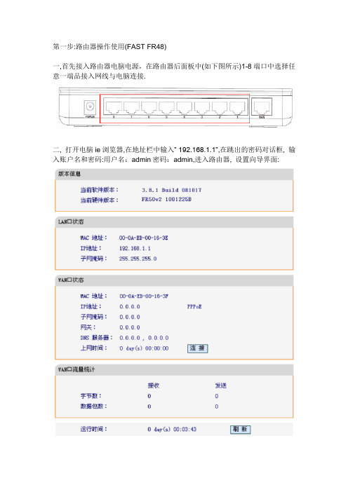
第一步:路由器操作使用(FAST FR48)一,首先接入路由器电脑电源,在路由器后面板中(如下图所示)1-8端口中选择任意一端品接入网线与电脑连接.二, 打开电脑ie浏览器,在地址栏中输入”192.168.1.1”,在跳出的密码对话框, 输入账户名和密码:用户名:admin密码:admin,进入路由器, 设置向导界面:三,点击窗口左侧的:WAN口设置,如图:四,进入设置页面后,按下图所示操作:1,在WAN连接类型下拉框列表中,选择”PPPoE”2,上网账号输现在每次拔号的用户名,密码.其他都为默认设置,单击”保存”按钮,退出设置页面.五,回到主设置页面后,同样点击左侧的DHCP服务器(如下图)点击窗口左侧DGCP服务.六,单击DHCP服务,进入设置页面,如图,进行如下操作:1,DHCP服务器选择启用;2,地址池开始地址输入:192.168.1.2地址池结束地址输入:192.168.1.99其他都为默认设置,单击”保存”按钮,退出设置页面.到此第一个路由器就设置这么多,然后把猫的网络口与路由器后面板的WAN 口连接.路由器自动有个2分钟的拔号过程,后绪,电脑连接此路由器后,就无须每台再进行单独拔号,就可以自动上网了.你试下,看是不是每台电脑都能上网.第二个路由器设置差不多,重复第三步,只是用户名和密码不一样,重复第六步的时候,址址池开始地址为:192.168.102,地址池结束地址为:192.168.1.199 回到主页后,再增加一个设置LAN设置:操作如下:在主设置页面中选择”网络参数—LAN设置”,点击进去后(如图),把IP地址一栏改为:192.168.101,这样改是为了后面两台路由器组成局域后后,不冲突.其他不变,点击保存退出,就可以了.两台路由器设置好后,就可以单独拔号上网了.以后所有的电脑只要连接上路由器就可以了.第二步电脑上相关设置如果电脑上网一直跳出拔号对话框的话,对电脑再进行更改.一,删除原拔号程序:1,回到桌面,选择”网上邻居”图标,右击,选择”属性”,进入对话窗口,删除如图所示的宽带(连接)图标.二,取消拔号连接程序,设置如下:1,打开浏览器,单击工具图A,选择nternet选项.图B”Internet选项”对话框.2,进入”Internet选项”对话框,单击””连接”选项图C择”从不进行拔号连接”图D. 3,单击确定按钮退出即可.。
CommScope 8 Ultra Low Loss OM4 双纤光纤连接器说明书
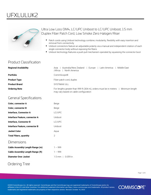
Ultra Low Loss OM4, LC/UPC Uniboot to LC/UPC Uniboot, 1.5 mmDuplex Fiber Patch Cord, Low Smoke Zero Halogen/RiserPatch cords using Uniboot technology combine, modularity, flexibility with easy insertion andremoval from connectivityUniboot connectors feature an adjustable polarity via a manual and independent rotation of eachsingle connector body without exposing the fibersUniboot technology features a push-pull mechanism operated by squeezing the connector bootProduct ClassificationRegional Availability Asia | Australia/New Zealand | Europe | Latin America | Middle East/Africa | North AmericaPortfolio CommScope®Product Type Fiber patch cord, duplexProduct Brand SYSTIMAX ULLOrdering Note For lengths greater than 999 ft (304 m), orders must be in meters | Minimum lengthmay vary based on cable configurationGeneral SpecificationsColor, connector A BeigeColor, connector B BeigeInterface, Connector A LC/UPCInterface Feature, connector A UnibootInterface, Connector B LC/UPCInterface Feature, connector B UnibootJacket Color AquaTotal Fibers, quantity2DimensionsCable Assembly Length Range (m) 1 – 999Cable Assembly Length Range (ft) 1 – 999Diameter Over Jacket 1.5 mm | 0.059 inOrdering Tree18Page ofPage of 28Mechanical SpecificationsCable Retention Strength, maximum 11.24 lb @ 0 ° | 4.40 lb @ 90 °Optical SpecificationsFiber ModeMultimode Fiber TypeOM4, LazrSPEED®Insertion Loss, maximum0.15 dB Insertion Loss, typical0.13 dB Return Loss, minimum 35 dBEnvironmental SpecificationsOperating Temperature-10 °C to +60 °C (+14 °F to +140 °F)Environmental Space Dual Rated LSZH/RiserRegulatory Compliance/CertificationsAgencyClassification CHINA-ROHSAbove maximum concentration value ISO 9001:2015Designed, manufactured and/or distributed under this quality management system ROHSCompliant/Exempted UK-ROHSCompliant/ExemptedIncluded Products760251280N-002-DU-5K-M15AQ/AY/LTS–Fiber Indoor Cable, LazrSPEED® Low Smoke Zero Halogen Light Duty Interconnect, 2 fiber, Multimode OM4, Gel-free, Meters jacket marking, Aqua jacket color 860660825860660825–LC UniBoot 1.5 mm Multimode Aqua LC UNIBOOT duplex connector38Page ofPage of 48Fiber Indoor Cable, LazrSPEED® Low Smoke Zero Halogen Light DutyInterconnect, 2 fiber, Multimode OM4, Gel-free, Meters jacket marking,Aqua jacket colorProduct ClassificationRegional AvailabilityEMEA PortfolioCommScope®Product TypeFiber indoor cable Product Series P-MPGeneral SpecificationsCable TypeMPO trunk cable Construction TypeNon-armored Subunit TypeGel-free Jacket ColorAqua Jacket MarkingMeters Total Fiber Count 2DimensionsDiameter Over Jacket 1.5 mm | 0.059 inRepresentative ImageMechanical SpecificationsMinimum Bend Radius, loaded30 mm | 1.181 in Minimum Bend Radius, unloaded 20 mm | 0.787 inTensile Load, long term, maximum30 N | 6.744 lbfTensile Load, short term, maximum100 N | 22.481 lbfCompression 4 N/mm | 22.841 lb/inCompression Test Method IEC 60794-1 E3Impact0.74 N-m | 6.55 in lbImpact Test Method IEC 60794-1 E4Strain See long and short term tensile loadsStrain Test Method IEC 60794-1 E1Twist10 cyclesTwist Test Method IEC 60794-1 E7Optical SpecificationsFiber Type OM4, LazrSPEED® 550Environmental SpecificationsInstallation temperature0 °C to +50 °C (+32 °F to +122 °F)Operating Temperature-10 °C to +60 °C (+14 °F to +140 °F)Storage Temperature-40 °C to +70 °C (-40 °F to +158 °F)Cable Qualification Standards IEC 60794-1-2Environmental Space IndoorEnvironmental Test SpecificationsHeat Age0 °C to +85 °C (+32 °F to +185 °F)Heat Age Test Method IEC 60794-1 F9Low High Bend0 °C to +70 °C (+32 °F to +158 °F)Low High Bend Test Method IEC 60794-1 E11Temperature Cycle-10 °C to +60 °C (+14 °F to +140 °F)Temperature Cycle Test Method IEC 60794-1 F1Packaging and WeightsCable weight 2.1 kg/km | 1.411 lb/kftRegulatory Compliance/CertificationsAgency Classification58Page ofCHINA-ROHS Below maximum concentration valueREACH-SVHC Compliant as per SVHC revision on /ProductCompliance ROHS CompliantUK-ROHSCompliant* FootnotesOperating Temperature Specification applicable to non-terminated bulk fiber cablePage of68LC UniBoot 1.5 mm Multimode Aqua LC UNIBOOT duplex connectorProduct ClassificationRegional Availability Asia | Australia/New Zealand | EMEA | Latin America | North AmericaPortfolio CommScope®Product Type Fiber connectorProduct Brand LazrSPEED® | SYSTIMAX ULLProduct Series UnibootGeneral SpecificationsBody Style DuplexColor BeigeInterface LC/UPCInterface Feature UnibootDimensionsCompatible Cable Diameter 1.5 mm | 0.059 inMaterial SpecificationsFerrule Material ZirconiaMechanical SpecificationsCable Retention Strength, maximum11.24 lb @ 0 ° | 4.40 lb @ 90 °Optical SpecificationsFiber Mode MultimodeInsertion Loss Change, mating0.3 dBOptical Components Standard ANSI/TIA-568-C.3Insertion Loss, maximum0.1 dBInsertion Loss, ULL, maximum0.15 dB0.13 dB78Page ofInsertion Loss, ULL, typical0.13 dBReturn Loss, minimum35 dBPackaging and WeightsPackaging quantity1* FootnotesInsertion Loss Change, mating TIA-568: Maximum insertion loss change after 500 matings88Page of。
8口交换机使用说明书
8口交换机使用说明书
◆8口交换机功能简介
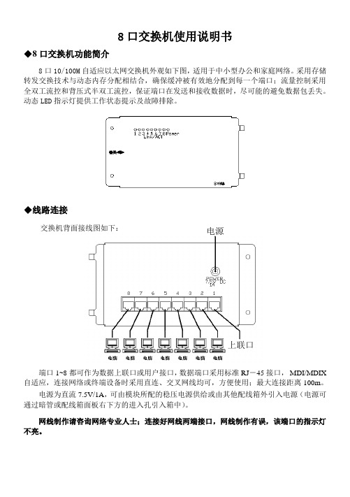
8口10/100M 自适应以太网交换机外观如下图,适用于中小型办公和家庭网络。
采用存储转发交换技术与动态内存分配相结合,确保缓冲被有效地分配到每一个端口;流量控制采用全双工流控和背压式半双工流控,保证端口在发送和接收数据时,尽可能的避免数据包丢失。
动态LED 指示灯提供工作状态提示及故障排除。
◆线路连接
交换机背面接线图如下:
端口1~8都可作为数据上联口或用户接口,数据端口采用标准RJ -45接口, MDI/MDIX 自适应,连接网络或终端设备时采用直连、交叉网线均可,方便使用;最大连接距离100m 。
电源为直流7.5V/1A ,可由模块所配的稳压电源供给或由其他配线箱外引入电源(电源可通过暗管或配线箱面板右下方的进入孔引入箱中)。
网线制作请咨询网络专业人士;连接好网线两端接口,网线制作有误,该端口的指示灯不亮。
电源 上联口。
巴法络路由器怎么设置

巴法络路由器怎么设置要想配置WBR-204g无线路由器,必须知道该路由器的治理IP。
华为3WBR-204g无线路由器、管理IP是192.168.1.1,用户名和密码都是admin。
接下来小编教你巴法络路由器怎么设置,希望对你有帮助。
将路由器与电脑用网线连接好之后,配置电脑IP地址,电脑的IP 地址必须与路由器的IP地址在同一个网段,即电脑的IP地址必须在192.168.2-192.168.1.254范围之内。
WBR-204g无线路由器登录界面在浏览器中输入192.168.1.1,输入用户名和密码之后就可以进入WBR-204g无线路由器的治理模式界面。
然后我们可以看到WBR-204g的各项菜单,由于治理界面是中文的,用户只要进行简单的配置一下就可以使用了。
下面,笔者具体讲解一下各个菜单的功能。
设置向导设置向导:设置向导可以指导用户一步一步的配置路由器,用户只要将自己的参数填写进去就可以完成路由器的配置。
设置向导中的具体选项与高级设置相同,下文会进行具体介绍。
WBR-204g无线路由器设置向导高级设置WBR-204g无线路由器的高级设置选项,与其他品牌路由器的设置选项相同,包括了WAN设置、LAN设置及无线设置等选项。
下面对每一个子菜单进行具体的介绍。
WAN口设置选项:WAN口设置主要是配置用户的上网方式。
用户将自己所用的网络接入模式及相关信息填写进去即可。
以PPPoE虚拟拨号为例,向用户介绍一下如何配置WAN口。
点击“WAN口连接类型”后会出现一个下拉菜单,选择PPPoE,然后将自己的上网帐号和密码填写进去,点击保存就可以了。
主机名和PPPoE服务名不必填写。
WAN口设置界面假如是静态IP用户,将IP地址及DNS服务器地址填写进去即可。
LAN口设置:LAN设置页面用于设定LAN口的IP地址和开启关闭DHCP服务。
建议保持缺省设置(LAN口IP 地址:192.168.1.1/24,启用DHCP服务器)。
- 1、下载文档前请自行甄别文档内容的完整性,平台不提供额外的编辑、内容补充、找答案等附加服务。
- 2、"仅部分预览"的文档,不可在线预览部分如存在完整性等问题,可反馈申请退款(可完整预览的文档不适用该条件!)。
- 3、如文档侵犯您的权益,请联系客服反馈,我们会尽快为您处理(人工客服工作时间:9:00-18:30)。
8uftp使用说明
一、安装
此软件是一个绿色软件,不需要安装,把它放在一个文件夹中置于任何盘下面都可以。
然后建立一个桌面快捷方式就好了
一、设立站点
点击左上侧图标,弹出如右图对话
框。
点击图中的“新站点”,建立一个你的
站点(可重命名)。
在主机名处输入
125.64.224.127地址,端口默认21,服务器
类型为FTP,再输入你的用户名和密码。
如
果你已修改了服务器的密码,请输入修改后
的密码,保存退出。
设置完成后如下图:
二、连接文件
点击这个图标中的小黑前头,选择你的站点,就可自动连接你的服务器中的文件。
三、本地目录设置
可在这个图中点小黑箭头选择你所要存储从服务器上下载来的文件,一般可在E盘设
置一个名叫“上级来文”的文件夹。
以
免重装系统后文件丢失。
四、文件夹及文件下载
文件夹下载:
从上图中选择要下载的文件夹,右键单击,单击“下载”,便可将此文件夹及里面的所有文件一并下载。
文件下载:
打开上图中你要下载文件的文件夹,双击里你要想下载的文件,便可将此文件下载到你所定义的本地文件夹中目录中。
如右图。
五、密码修改
单击菜单中的“服务器”,在下拉菜单中单击“密码修改”,便可修改你自己的密码。
注意:必须是在你的站点连接的状态下才能修改。
而且密码修改后同时也要修改你的站点密码。