Autodesk Inventor工程图启始设置
Inventor三维绘图基础
Inventor 三维绘图基础
在二 维草图环 境中画出 单个螺纹 截面和旋 转轴
Inventor 三维绘图基础
进入三维造型环境,在“零件特征”工具栏里点 击“螺旋扫掠”,在“螺旋扫掠”对话框里和三维实 体上分别点击“截面轮廓”、旋转轴和“切割”。
Inventor 三维绘图基础
在“螺旋扫掠”对话框里点击“螺旋尺寸”, 初步调整螺距和圈数。
中需要确定Φ21.38和
Φ25.07的平面中心相
O
对位置尺寸,因此, 需要分别求作Φ20或
Φ30截面圆心相对于
Φ21.38和Φ25.07圆心
的投影位置尺寸。
Inventor 三维绘图基础
首先,在二维环境中作出Φ20截面,在三维环 境中作出Φ20截面所在的Ⅰ (X—Y)平面。
Inventor 三维绘图基础
Inventor 三维绘图基础
例1:二维扫掠(扫掠的路径仅存在于一个平面) 根据已知条件,创建图示具有二维扫掠特征的实体。
Inventor 三维绘图基础
根据平面图形,在二维环境中先创建第一个扫掠截 面Φ20,并对其建立截面所在平面:工作平面Ⅰ (X— Y)。
Inventor 三维绘图基础
过扫掠截面Φ20的圆心,创建扫掠路径所在平面:工作平面Ⅱ (Y—Z)。 将工作平面Ⅱ 置于二维环境中,创建扫掠路径,并回到三维环境中。
Inventor 三维绘图基础
在三维造型环境中用“拉伸—切割”命令,对六 角螺栓头切割造型并点击“确定”。
Inventor 三维绘图基础
对螺栓六角头赋予金属感质地强的材料。
Inventor 三维绘图基础
例4:以上图为例,创建一个三维实体六角螺母。
Inventor 三维绘图基础
Autodesk Inventor基础培训教程
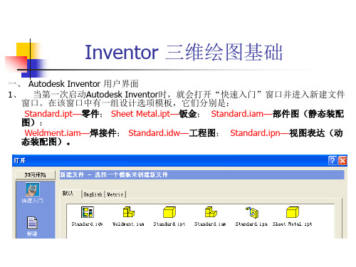
Autodesk Inventor基础培训教程1. Inventor界面介绍●∙简洁的工作环境●∙启动引导模板●∙Inventor文件格式●∙右键关联菜单●∙按任务自动调整的智能型工具条和菜单系统●∙Inventor项目设置●∙系统环境设置:工具> 选项●∙Inventor设计环境:零件设计、部件设计、工程图设计和表达视图设计(爆炸场景)●∙Inventor零件造型的钣金环境和实体造型环境(钣金零件设计和实体零件设计)。
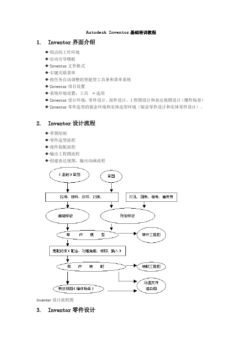
2. Inventor设计流程●∙草图绘制●∙零件造型流程●∙部件装配流程●∙输出工程图流程●∙创建表达视图,输出动画流程Inventor设计流程图3. Inventor零件设计3.1 Inventor零件设计流程Inventor零件设计流程图3.2 Inventor零件设计:草图绘制●∙简洁的草图绘制工具●∙基于“手势”的绘图●∙目标动态捕捉(提示符号)●∙约束的显示、添加、删除●∙尺寸标注、尺寸关联●∙投影草图●∙草图的动态拖拽(练习1)绘制如图所示的草图。
练习内容:1. 多重封闭截面轮廓的使用。
2. 练习创建草图平面、定位特征、在创建过程中调整观察模式。
3. 造型练习。
尝试以不同的方法创建相同的零件。
4. 改变零件的材料、颜色等。
5. 特征镜像。
6. 设计元素的创建和引用。
7. 创建工程师记事本。
达到要求:1. 完成零件几何造型。
2. 按给定尺寸和约束完成减重槽的草图。
3. 完成减重槽的创建并做镜像特征,观察结果。
4. 用减重槽创建一个设计元素,尝试不用镜像而用插入设计元素的方法创建另一侧的减重槽。
5. 调整零件材料、颜色,观察显示效果。
6. 完成时间为20到30分钟。
4. 部件装配设计●∙部件装配环境介绍●∙自下而上和自上而下的装配模式●∙在位编辑零件●∙装配约束:配合、对准角度、相切、插入●∙基于装配约束的零件拖动●∙约束驱动4.1 Inventor部件装配约束●∙装配约束的本质:控制两个零件之间的相对自由度●∙装配约束的实现:两零件的点、线、面之间的配合●∙Inventor装配约束类型(练习3)打开指定的部件文件【装配.iam】,如下图:通过添加装配约束,得到下面的部件:现在,缺少紧固件。
Autodesk Inventor 设计自动化指南说明书

AUTODESK INVENTOR Trial ProjectsDesign AutomationDesign a conveyor assemblyIn Inventor, click the ‘Projects’ icon in the ribbon. Navigate to where you saved the project files and select Assembly Convey-or DA.ipj . Then open Assembly Conveyor DA.iam .Access the ‘Design’ tab in the ribbon and click ‘Bolted Connec-tion’, located in the ‘Fasten’ panel.Select ‘Concentric’ from the drop-down for the ‘Placement’.Select the face shown for the ‘Start Plane’.2.4.1.3.Select a ‘Circular’ reference on the yellow bracket for the loca-tion.Choose the back face of the yellow bracket for the fastener ‘Termination’.Define the ‘Thread ‘using an ‘ANSI Metric M Profile’, and then set the ‘Diameter’ to 5mm.Select ‘Click to add a fastener’ in the dialog to select a‘Standard’ and ‘Category’.6.8.5. 7.Filter to ‘ANSI, Socket Head Bolts’, and select the ‘Forged Socket Head Cap Screw - Metric option’.Select ‘Click to add a fastener’ below the screw you just insert-ed, and then insert the ‘Plain Washer (Metric)’ component.Drag the arrow at the end of the fastener preview to define the correct length. Click ‘OK’ on the dialog to create the bolted connection.Click ‘OK’ again the accept the default ‘File Naming’ for the newsubassembly.10.12.9.11.Right-click on the new bolt subassembly and select ‘Copy’ from the marking menu.Right-click in empty space and select ‘Paste’ to insert another in-stance of the component. Note that it’s listed as a subassembly within the feature tree, and not as an original bolted connection.Selecting ‘Constraint’ from the marking menu, create a ‘Mate’ between the front face of the bracket and this face on the washer.Create another ‘Mate’ constrain between the centerline of thescrew and the centerline of the remaining hole.14.16.13.15.Right-click on the original bolt and select ‘Edit’ using ‘DesignAccelerator’.Click to add a fastener beneath the existing washer listing.Insert an instance of the ‘ASME B 18.21.2M’ lock washer to the stack, and then drag it in between the two existing components in the list.Click ‘OK’ to apply the change, and notice how the copiedsubassembly updates to reflect the change as well. 18.20.17.19.Activate the ‘Pattern’ command from the ‘Assemble’ tab in the ribbon. Select both of the bolt subassemblies for the compo-nents to pattern.From the rectangular pattern tab in the dialog, select an edge along the X axis to define the first pattern direction.Choose ‘Measure’ for the distance option, and then select the faces shown. Click ‘OK’ to apply the pattern.Access the ‘Design’ tab in the ribbon and click‘Bolted Connection’ again.22.24.21.23.Define the ‘Placement’ as ‘By hole’.Select the front face of the blue bracket for the ‘Start Plane’,and then click on one of the holes at the bottom of the bracketfor the location.Select the face on the opposite side of the mount for the ‘Termination’ definition.Select ‘Click to add a fastener’ in the dialog.26.28.25.27.Filter to ‘ANSI, Socket Head Bolts’, and select the‘Forged Socket Head Cap Screw - Metric’ option again.Click to add a fastener below the screw, inserting a ‘Plain Washer (metric)’.Add a third fastener to the list, choosing the ‘ASME B18.21.2M’ lock washer, and then drag it in between the screw and plain washer in the list.Select ‘Click to add a fastener’ below the ‘Selected Hole’ listing,and then choose the ‘Hex Nut Metric’ component within the‘ANSI, Nuts’ category.30.32.29.31.Adjust the cap screw length to 30mm.Check ‘Follow pattern’ in the dialog.Click ‘OK’ twice to place an instance at each hole in the pattern, and to accept the default ‘File Naming’. Save your progress to continue.Continue using ‘Design Automation’ to create a shaft connect-ing the motor and the drive pully.34.36.33.35.Activate the ‘Shaft’ command, located in the ‘Power Transmission’ panel on the ‘Design’ tab.Click the eraser icon at the upper-right of the ‘Shaft Compo-nent Generator’ dialog to reset the calculation data, and then click ‘OK’.Zoom into the drive portion of the motor and select the inner cylindrical face for the first ‘Placement’ definition.Select the back face of the drive motor pully for the shaft’s‘Start plane’ definition.38.40.37.39.Select the outer face of the motor cover for the shaft’s orientation definition.If required, use the flip direction button to ensure the shaft is oriented correctly.Double-click an arrow glyph for the first shaft section to enter a specific value of 8mm.Double-click the listing in the dialog to edit the section length.42.44.41.43.Enter a length of 30mm and click ‘OK’.Define the second edge of the shaft section as having‘No feature’.Double-click the next section in the list to edit it, setting a di-ameter of 10mm and a length of 23mm. Keep the default edge definitions as well.Change the section type for the third listing to ‘Cylinder’ andselect ‘Yes’ to confirm.46.48.45.47.Adjust the third section’s diameter, making it 12mm.Drag the arrow glyph to set the length of this section at 48mm.Define a ‘Chamfer’ for the second edge of the section, using the values shown.For the last shaft section, drag both the diameter and length to10mm.50.52.49.51.Define a ‘Chamfer’ for the second edge of the section, using a ‘Distance of 0.5mm’ and an ‘Angle of 45deg’.Access the section features drop-down for the third shaft sec-tion, and then select ‘Add Wrench’ to add some flat spots for the pully key onto.Define the feature at 26mm long and 11mm deep.Click ‘Add Wrench’ again to define a second feature with the same dimensions.54.56.53.55.Drag the blue arrow in the graphics area to rotate the second feature 90deg about the shaft. Click ‘OK’ twice to create the shaft and accept the default ‘File Naming’.Double-click on the shaft to view it clearly, and to confirm itwas created as intended. Save all of your files to finish. 58.57.Autodesk, Autodesk Inventor, and the Autodesk logo are registered trademarks or trademarks of Autodesk, Inc., and/or its subsidiaries and/or affiliates in the USA and/or other countries. All other brand names, product names, or trademarks belong to their respective holders. Autodesk reserves the right to alter product offerings and specifications at any time without notice, and is not responsible for typographical or graphical errors that may appear in this document.© 2017 Autodesk, Inc. All rights reserved.。
auto inventor工程图
肋不剖的处理方法
Inventor按模型剖切后的实际形体投影,肋板纵向剖切时被打上了 剖面线,与国标不符,需手动处理: 1.隐藏剖面线(选中剖面线→ 右键菜单“隐藏”)
2.创建草图→投影几何图元→画肋与相邻结构的分界线→填充
隐 藏 草 图
约 束
填 充
斜视图
修剪视图习题集9-4
步骤一:零件建模 步骤二:工程图“基础视图”
样式编辑器
选项卡“管理”→样式编辑器
将“局部剖线”和“打 断线”设为“可见窄的”
样式编辑器
图形区中对尺寸等标注右键→编辑尺寸样式 等新 其建 他文 地本 方样 调式 用如 “ 小 字 体 ” , 在 尺 寸
更改图名
设置比例
设置显示样式
步骤三:创建斜视图
单击选中 基础视图
单击边确定 斜视方向
拖动鼠标放 置斜视图
步骤四:修剪视图
设置线条可见性Βιβλιοθήκη 选中斜视图框选裁剪区域
步骤五:整理成图
右键快捷菜单→对齐视图→断开 调整视图位置 修改标注 放置中心线
断裂画法
习题10-1 轴
单击选中视图→单击选择断裂首末位置 样式库中更改 折断线
机械与电气工程学部
工 程 图
一、工程图模板
二、创建零件工程图
三、创建部件工程图 四、标注、明细栏
工程图模板 机械设计的最后一步 设计意图及设计结果细化的图纸
工程图
设计者与制造者交流的载体
产品检验及审核的依据
二维工程图与三维实体模型相关联——系统默认“允许从 工程图修改零件”,可更改。
Inventor提供的模板:
投影视图
创建基本视图后自动进入“投影视图”命令,
移动鼠标→单击左键→右键 →“创建”
2024版Inventor基础教程[1]
![2024版Inventor基础教程[1]](https://img.taocdn.com/s3/m/de0f96765627a5e9856a561252d380eb629423dc.png)
逐步完善
随着版本的迭代更新,Inventor 逐步增加了更多功能和工具,如
钣金设计、管路设计等。
现状与发展趋势
如今,Inventor已经成为一款功 能强大的三维CAD软件,广泛应 用于各个行业。未来,Inventor 将继续致力于提高用户体验和增
加新功能。
Inventor应用领域
01
02
03
04
机械设计
装配体概念
装配体是由多个零部件组成的整体, 用于模拟实际产品的结构和功能。
零部件约束
在装配体中,可以使用各种约束来定 义零部件之间的相对位置和关系,如 配合、对齐、角度等。
装配体分析
可以对装配体进行干涉检查、运动仿 真等分析,以验证设计的正确性和可 行性。
爆炸视图
通过爆炸视图可以清晰地展示装配体 的内部结构和零部件之间的相对位置 关系。
材质调整
掌握材质编辑器使用方法, 调整材质属性如反射、折 射、透明度等,以达到更 真实的渲染效果。
灯光和阴影调整策略
灯光类型
01
了解不同灯光类型(如点光源、平行光、环境光等)及其特点,
根据需要选择合适的灯光。
阴影设置
02
学习如何调整阴影参数,如阴影贴图分辨率、阴影颜色等,使
阴影更自然、逼真。
灯光布局
视图样式设置
视图窗口管理
可以设置视图的样式和属性,如背景色、网 格线、坐标系等,提高视觉效果和操作便利 性。
支持多个视图窗口的同时打开和管理,方便 用户进行多视角查看和比较。
03
草图绘制基础
草图环境设置与进入方式
草图环境设置
在进入草图模式之前,需要设置草图环境,包括选择草图平面、设置草图方向、调 整草图网格等。
Autodesk Inventor 2013课件第9章 创建工程图

文本标注
9.5.5 课上十分钟——指引线文本标注
v 也可以为工程图添加带有指引线的文本注释。需要 注意的是如果将注释指引线附着到视图或视图中的 几何图元上,则当移动或删除视图时,注释也将被 移动或删除。
v 【执行方式】 v 功能区:单击“标注”标签栏“文本”面板上的“文本”按
9.5.1 课上十分钟——表面粗糙度标注
v 表面粗糙度是评价零件表面质量的重要指标之一,它对零件 的耐磨性、耐腐蚀性、零件之间的配合和外观都有影响。
v 【执行方式】 v 功能区:单击“标注”标签栏“符号”面板上的“粗糙度”按钮。 v 【操作步骤】 v 1.不带指引线的标注 v 打开随书光盘“源文件”文件夹下“第9章\课上十分钟\不带指引
9.2.5 课上十分钟——局部视图
v 局部视图可以用来突出显示父视图的局部特征。局 部视图并不与父视图对齐,缺省情况下也不与父视 图同比例。
v 【执行方式】 v 功能区:单击“放置视图”标签栏“创建”面板上的“局
部视图”工具按钮。 v 【操作步骤】 v 打开随书光盘“源文件”文件夹下“第9章\课上十分钟\
9.3 修改视图
v 本节主要介绍打断视图、局部视图、断面视 图的创建方法,以及对视图进行位置调整。
9.3.1 课上十分钟——打断视图
v 打断视图是通过修改已建立的工程视图来创建的, 可以创建打断视图的工程图有零件视图、部件视图、 投影视图、等轴测视图、剖视图、局部视图也可以 用打断视图来创建其他视图。
按钮。 v 【操作步骤】 v 打开随书光盘“源文件”文件夹下“第9章\课上十分钟\
明细栏”,操作过程如图所示。
生成明细栏
生成明细栏(续)
9.7 综合演练十分钟——柱塞泵工程图
inventor 2020 基准目标符号

inventor 2020 基准目标符号
在 Autodesk Inventor 2020 中,基准目标符号是用于指示特定基准或参考点的符号。
这些符号可以帮助用户在图纸或模型中清晰地标识重要的基准点或目标点。
要使用基准目标符号,请按照以下步骤操作:
1. 在功能区上,单击“标注”选项卡,然后选择“符号”面板。
2. 在“符号”面板中,选择“基准目标”选项。
3. 根据需要选择适当的基准目标类型,例如“指引线基准起点”、“直线基准起点”、“矩形基准起点”、“圆基准起点”或“点基准起点”。
4. 在图形窗口中单击以设置所需的基准起点。
5. 移动光标并单击以添加顶点或指示器到指引线。
6. 当符号指示器位于所需位置时,单击鼠标右键,选择“继续”放置符号。
此时将打开“基准目标符号”对话框。
7. 在“基准目标符号”对话框中,输入适当的尺寸值和基准信息。
8. 单击“确定”以放置符号。
9. 如果需要堆叠基准目标符号,请在现有基准目标符号上单击鼠标右键,然后从菜单中选择“附着引出序号”。
10. 完成后,单击鼠标右键,然后选择“取消”以取消放置状态。
通过以上步骤,您可以在 Autodesk Inventor 2020 中成功地添加基准目标符号,以便在图纸或模型中标识重要的基准点或目标点。
Inventor 创建和编辑教程

创建和编辑"放置特征"(1)在教程中,将学习如何放置和编辑零件特征。
其中的练习可指导您逐步完成创建孔、圆角、倒角、螺纹、抽壳、环形和矩形阵列、镜像特征以及分析面等等的操作。
一、添加放置特征放置特征是常用的工程特征,使用Au to de sk I nv en t or创建它们时不需要使用草图。
创建这些特征时,通常只需提供位置和一些尺寸。
标准的放置特征包括抽壳、圆角、倒角、拔模斜度、孔和螺纹。
以下是部分用于放置特征的工具,它们位于“零件特征”工具面板中:圆角--在所选的边上放置圆角或全周边圆角。
倒角--打断锐角边。
从外部边界上删除材料并且可以将材料添加到内部边界上。
孔--将指定的孔(可以带螺纹)放置到零件中。
螺纹--在圆柱面或圆锥面上创建普通和锥形内外螺纹。
抽壳--抽壳生成空心零件,壁厚由用户定义。
矩形阵列--创建矩形特征阵列。
环形阵列--创建环形特征阵列。
镜像特征--在平面的另一侧创建镜像。
使用对话框定义放置特征的值,例如下图中的“打孔”对话框。
二、孔特征使用A ut od es k I nv en to r,可以创建各种孔:■直孔■沉头孔■倒角孔■沉头平面还可以使用以下三个终止方式选项之一来指定孔的深度:“距离”、“贯通”和“到”。
使用“孔底”选项设置平底或带角度的孔底。
也可以将孔分类为简单孔、配合孔、螺纹孔或锥形螺纹孔。
但是,您无法创建沉头孔类型的锥形螺纹孔。
创建螺纹孔或锥形螺纹孔时,螺纹数据和孔一起保存;激活任意等轴测视图时将显示螺纹。
练习:在零件上创建孔特征1激活t ut or ia l_f i le s 项目后,打开“Up pe r_Pl at e.i p t”文件。
2在“零件特征”工具面板中,单击“打孔”工具。
3从“孔”对话框的“放置”下拉列表中选择“线性”。
4单击“面”按钮,然后在图形窗口中,单击要放置孔的面5单击面的边以指定引用1,然后单击面的另一条边以指定引用2。
- 1、下载文档前请自行甄别文档内容的完整性,平台不提供额外的编辑、内容补充、找答案等附加服务。
- 2、"仅部分预览"的文档,不可在线预览部分如存在完整性等问题,可反馈申请退款(可完整预览的文档不适用该条件!)。
- 3、如文档侵犯您的权益,请联系客服反馈,我们会尽快为您处理(人工客服工作时间:9:00-18:30)。
Autodesk Inventor工程图启始设置.
1.打开Autodesk Inventor软件。
“新建”“Standard.dwg”打开工程图界面。
2.右击“图纸:1”下“GB1”的标题栏,选删除。
3.右击“工程图资源”下“标题栏”,选“定义新标题栏”。
进入草图绘制格式。
4.点击“插入”/“ACAD”,查找一个”CAD,dwg文档”中一个没有属性的标题栏图框。
打开插入。
5.点击“修改”/“移动”命令,选择整个标题栏,点击“移动”对话框中,基点选择箭头,捕着标题栏的点与图框中的点,
移到拾当位置。
6.点击“完成草图”,输入标题栏名称,保存。
7.右击“工程图资源”下“标题栏”中所创建的新标题栏。
点击插入。
即可将其插入到图纸中。
8.右击“图纸:1”“编辑图纸”,可任意创建图纸格式与方向。
标题栏块会自动插入右下角。
9.点击左上角“I”图标,选择“另存为”、“保存副本为模板”。
输入名称,保存。
下次在“新建”的默认对话框中便自动出
献所创建的工程图图框使用。
10.新建工程图,打开所创建的图框。
11.右击“工程图资源”下“标题栏”中所创建的新标题栏,选择“编辑”,界面更换为标题栏的草绘界面。
12.点击“绘图”面板“文本”命令。
在标题栏中名称位置处,选择放置范围,弹出文本对话框。
设置文字居中与大小后,点
击“类型”框中下拉箭头,选择“特性-模型”,点击“特性”框中下拉箭头,选择“主题”,点击后面添加文本箭头。
“确定”加入文本。
重复加入“特性-模型”的“零件代号”,“自定义特性-模型”的“材料”,“物理特性-模型”,“质量”。
点击“完成草图”,“是”保存所做的编辑。
13.重复第九步,复盖工程图模板。
14.在实体模型中右击模型树下实体名称,选择“iproperties(I)”在此设置工程图中所链接的“特性-模型”的属性与之对应。
15.新建工程图,打开所创建的图框。
16.点击“基础视图”弹出工程视图对话框。
点击“打开现有文件”查找打开模型,设置比例、可在方向下点击“改变视方向”,
进入调整放置视图。
“确定”放置插入。
完成其它视图后。
17.“标注”/“尺寸”。
标注第一个尺寸后,右击所标注的尺寸,选择“编辑尺寸样式”,弹出“样式和标准编辑器”对话框,
点击“标准”前+,选择“默认标准”,点击右侧“新建”。
创建“副本默认标准(GB)”在此设置使用的定义。
之后点击“标准”,右击右侧“标准框中”的“副本默认标准(GB)”选择“激活。
”
18.点击“尺寸”,再点击“格式”中“按标准”选择“副本默认(GB)”再进行尺寸标注。
19.“工具”,“应用程序选项”“工程图”在默认对象样式与默认图层样式中选用“按上次使用的样式”。
20.在所有设置完善后,删除所有视图的信息。
重复第13步。