
横河测试测量数采仪GP10GP20便携式无纸记录仪的突出点
横河测试测量数采仪:GP10/GP20便携式无纸记录仪的突出点
YokogawaGP10/GP20便携式无纸记录仪可以实现更高的清晰度、更好的智能化、更强的访问性,让测量、显示和处理数据变得更加轻松,例如:
数据冗余
通过内部存储器和外部存储介质实现数据冗余。
防尘防水保证高显示品质
位于触摸屏表面的保护膜,其前后两面均涂有特殊涂层。
这样不但可以避免屏幕划伤,防止化学品和溶剂的腐蚀,还可以保持屏幕的高清显示和抗强光显示。
* 通过抑制因光干涉产生的牛顿环(同心圆环),可以提高视觉清晰度。
数据保持格式可选(二进制或文本)
如果希望提高数据的安全性,可以将测量数据保存为二进制格式。
此格式很难被传
统的文本编辑器及程序破译或修改。
但是如果希望用文本编辑器或电子表格程序直
接打开数据,则可以选择文本格式。
这样无需使用专用软件便可对测量数据进行处
理。
大容量内部存储器
显示数据文件的采样时间测量CH=30通道、运算CH=0通道内部存储器500MB
显示更新(分/div)30分钟
采样周期(s)60秒
总采样时间约2.5年
事件数据文件的采样时间测量CH=30通道、运算CH=0通道内部存储器500MB
采样周期(s) 1秒
总采样时间约1个月
符合标准
两点触屏技术
传统的电阻式触摸屏只能检测到一个触摸点。
而GP的内置控制器拥有特殊运算方法,在趋势监测时可以使用平移或缩放功能,是全世界首款采用两点触摸屏技术的无纸记录仪。
横河无纸记录仪DX1000

General Specifications <<Contents>> <<Index>> GS 04L41B01-01E DAQSTATION DX1000OVERVIEWThe DX1000 is a DAQSTATION that displays real-time measured data on a color LCD and saves data on a CompactFlash memory card (CF card). It can be hooked up to network via Ethernet, which enables to inform by E-mail and to monitor on Web site as well as to transfer files by using FTP. Also, it can communicate with Modbus/RTU or Modbus/TCP.It comes with a two, four, six-channel or twelve-channel model. As the input signal, a DC voltage, thermocouple, resistance temperature detector, or contact signal can be set to each channel. The data saved on a CF card can be converted by data conversion software to Lotus 1-2-3, Excel, or ASCII format file, facilitating processing on a PC. Not only this, the Viewer software allows a PC to display waveforms on its screen and to print out wave-forms.STANDARD SPECIFICATIONSGeneral SpecificationsConstructionMounting:Flush panel mounting (on a vertical plane)Mounting may be inclined downward up to30 degrees from a horizontal plane. Allowable panel thickness:2 to 26 mmMaterial:Case: drawn steelBezel: polycarbonateDisplay filter: polycarbonateCase color:Case: Grayish blue green(Munsell 2.0B 5.0/1.7 or equivalent)Bezel: Charcoal grey light(Munsell 10B 3.6/0.3 or equivalent)Front panel:Water and dust-proof*(based on IEC529-IP65 and NEMA No.250TYPE4 for indoor locations (except externalicing test))*Except for side-by-side mounting. Dimensions:144 (W) ϫ144 (H) ϫ224.1 (D) mm144 (W) ϫ144 (H) ϫ228.5 (D)* mm*In case of /H2 or /PM1 option is specified. Weight:approx. 2.9 kg**without optional features InputNumber of inputs:DX1002: two channelsDX1004: four channelsDX1006: six channelsDX1012: twelve channelsMeasurement interval:DX1002, DX1004:125 ms, 250 ms, 25 ms (fast samplingmode*)DX1006, DX1012:1 s (Not available when A/D integrationtime is set to 100 ms), 2 s, 5 s, 125 ms(fast sampling mode*)* A/D integration time is fixed to 1.67 ms in case offast sampling mode.Inputs:DCV (DC voltage), TC (thermocouple), RTD(resistance temperature detector), DI (digitalinput for event recording), DCA (DC currentwith external shunt resistor attached)GS 04L41B01-01E©Copyright November. 20051st Edition Nov. 2005(KP)8th Edition Dec. 2008(KP)All Rights Reserved. Copyright © 2005, Yokogawa Electric Corporation GS 04L41B01-01E 8th Edition Dec. 19,2008-00Input typeRange 0.0 to 1760.0°C0.0 to 1760.0°C0.0 to 1820.0°C–200.0 to 1370.0°C –200.0 to 800.0°C–200.0 to 1100.0°C –200.0 to 400.0°C–270.0 to 1300.0°C 0.0 to 2315.0°C–200.0 to 900.0°C–200.0 to 400.0°C0.0 to 2400.0°C–200.0 to 600.0°C–200.0 to 550.0°C OFF : less than 2.4 VON : more than 2.4 V Contact ON/OFFDCVTCRTD DI*1 R, S, B, K, E, J, T, N: IEC584-1 (1995), DIN IEC584,JIS C 1602-1995*2 W: W-5% Re/W-26% Re (Hoskins Mfg. Co.), ASTM E988*3 L: Fe-CuNi, DIN43710, U: Cu-CuNi, DIN43710*4 WRe: W-3%Re/W-25%Re (Hoskins Mfg. Co.)*5 Pt100: JIS C 1604-1997, IEC 751-1995, DIN IEC751-1996 JPt100: JIS C 1604-1989,JIS C 1606-1989 Measuring current: i = 1mA32 to 3200°F 32 to 3200°F 32 to 3308°F –328 to 2498°F–328.0 to 1472.0°F –328.0 to 2012.0°F–328.0 to 752.0°F –454 to 2372°F32 to 4199°F –328.0 to 1652.0°F –328.0 to 752.0°F 32 to 4352°F –328.0 to 1112.0°F –328.0 to 1022.0°F Measuring range –20.000 to 20.000 mV –60.00 to 60.00 mV –200.00 to 200.00 mV –2.0000 to 2.0000 V –6.000 to 6.000 V –0.800 to 5.200 V –20.000 to 20.000 V –50.00 to 50.00 V20 mV 60 mV 200 mV 2 V 6 V 1-5V 20 V 50 V R *1S *1B *1K *1E *1J *1T *1N *1W *2L *3U *3WRe *4Pt100*5JPt100*5DCV input (TTL)Contact inputA/D integration time:20 ms (50 Hz), 16.7 ms (60 Hz), 100ms (50/60Hz for DX1006/1012), or AUTO selectable (automatic selection by detection of power supply frequency)A/D integration time is fixed to 1.67 ms (600Hz) in case of fast sampling mode.Thermocouple burnout:Burnout upscale/downscale function can be switched on/off (for each channel).Burnout upscale/downscale selectable Normal: Less than 2 k ⍀, Burn out: More than 100 k ⍀Detection current: approx. 10 A1-5V range burnout:Burnout upscale/downscale function can be switched on/off (for each channel).Burnout upscale/downscale selectable Upscale burnout: More than +10% of configured spanDownscale burnout: Less than -5% of configured spanMoving average:Moving average on/off selectable for each channelMoving average cycles 2 to 400 selectableCalculation:Differential computation:Between any two channelsAvailable for DCV, TC, RTD and DI ranges.Linear scaling:Available for DCV, TC, RTD and DI ranges.Scaling limits: -30000 to 30000Decimal point: user-selectableEngineering unit: user-definable, up to 6charactersOver value: Exceeds ؎ 5% of scaling limits (on/off selectable)Square root:Available for DCV range.Scaling limits: -30000 to 30000Decimal point: user-selectableEngineering unit : user-definable, up to 6charactersLow level cut off: 0.0 to 5.0% of display spanOver value: Exceeds ؎ 5% of scaling limits (on/off selectable)1-5VDC scaling:Available for 1-5VDC range.Scaling limits: -30000 to 30000Display span limit: 0.800 to 5.200Decimal point: user-selectableEngineering unit : user-definable, up to 6charactersLow level cut off: Fixed to lower span limit Over value: Exceeds ؎ 5% of scaling limits (on/off selectable)DisplayDisplay unit:5.5-inch TFT color LCD (VGA, 320 x 240pixels)Note)In the part of crystal display, there are some pixelsthat can't always turn on or off. Please understand that the brightness of screen looks uneven because of characteristics of crystal display, but it is not out of order.Display group:Each measurement channel and computation channel can be assigned to display group of the trend, digital and bargraph display.Number of display: 10 groupsNumber of assignable channels for one group: 6 channelsDisplay color:Trend/Bargraph:Selectable from 24 colorsBackground:White or black selectableTrend display:Trend display type:Vertical, horizontal, landscape, horizontal or split selectableNumber of indication channels:6 channels per display (maximum)Number of display:10 displays (10 groups)Line width:1, 2, and 3 pixels selectableScales:Maximum 6 scales.Bargraph, green band area and alarm mark can be displayed on scale display.Number of divisions: Selectable from 4 to 12 or C10 (10 divisions by main scalemark and scale values are displayed on 0,30, 50, 70 and 100% position).Waveform span rate:5, 10, 15, 30, sec.,1, 2, 5, 10, 15, 20, 30min., 1, 2, 4, 10 hours/div selectable(5, 10 sec/div is available for only DX1002and DX1004)Bargraph display:Direction: Vertical or horizontal selectableNumber of indication channels:6 channels per displayNumber of display:10 displays (10 groups)Scales:Green band area and alarm mark can bedisplayed on scale display.Number of divisions: Selectable from 4 to12Reference position: Left, right or center Display renewal rate: 1 sDigital indication:Number of indication channels:6 channels per displayNumber of display:10 displays (10 groups)Display renewal rate: 1 sOverview display:Number of indication channels:Measuring values and alarm status of allchannelsInformation display:Alarm summary display:Display the list of latest 1000 alarmssummary.Jump to historical trend display by cursorpointing.Message summary display:Display the list of latest 450 messages andtime.Jump to historical trend display by cursorpointing.Memory information:Display the file list in internal memory.Jump to historical trend display by cursorpointing.Report information:Display the report data in internal memory. Modbus status:Display the Modbus status.Relay status:Display the on/off status of internal switchand relay output.Stacked bar graph display:Display the periodic sums of report data. Event switch status:Display the event switch status.Log display:Log display types:Login log, error log, communication log,FTP log, Web log, E-mail log, SNTP log,DHCP log, Modbus logTags:Display the tag number and tag comment.Tag number:Number of characters:16 characters maximumTag comment:Number of characters:32 characters maximumMessages:Number of characters:32 characters maximumNumber of messages:100 messages (including 10 free mes-sages)Message adding function:Message can be added on historicaldisplay.Other display contents:Status display area:Date & time (year/month/day,hour:minute:second), batch name (batchnumber + lot number), login user name,display name, internal memory status,status indication iconTrend display area:Grid lines (number of divisions selectablefrom 4 to 12), hour : minutes on grid, triplevels (line widths are selectable from 1, 2and 3 pixels)Data referencing function:Display the retrieved data (display data or event data)from internal or external memory.Display format:Whole display or divided to 2 areasTime axis operation:Display magnification or reduction, scrollby key operationData searching operation:Display the retrieved data from internalmemory by specifying date and time. Display auto scroll function:Display group of monitor display (trenddisplay, bargraph display and digital display)automatically changes in a preset interval(5, 10, 20, 30 s and 1 min).LCD saver function:The LCD backlight automatically dims or off(selectable) if no key is touched for a certainpreset time (can be set from 1, 2, 5, 10, 30,and 60 min).Display register function:Up to 8 display types can be registered withdisplay name.Display auto return function:The display type automatically returns toregisterd display type if no key is touchedfor a certain preset time (can be set from 1,2, 5, 10, 20, 30 and 60 min)Temperature unit:°C or °F selectableCustom display function:Display can be customized by lay outing display parts. Display data is saved in internal memory or external medium.Number of customized display:28 displays maximum (3 in internalmemory and 25 in external medium) Display part:- General parts (digital, bar, label, tagnumber, tag comment, )- Scale parts- Trend parts- List parts (alarm list, message list)- Figure parts (line, rectangle, circle)Edit function:Select parts, grid, edit parts (move, resize,property, copy, paste, layout orderchange, dependency of visual property),All Rights Reserved. Copyright © 2005, Yokogawa Electric Corporation GS 04L41B01-01E8th Edition Dec. 19,2008-00group control, delete, save display Custom display data:Contents:Display contents data (foreach display)Format:TextOutput:External mediumCustom display data save/load:Each or all custom display data file can besaved in specified directory.Custom display data can be loaded fromspecified directory.Data Saving FunctionExternal storage medium:Medium:CompactFlash memory card (CF card)Format:FAT16 or FAT32Internal memory:Medium:Flash memoryCapacity:Selectable from 80MB or 200MBMaximum number of files can be saved:400 files (total number of display data fileand event data file)Manual saving:Data files in internal memory can be saved manually.Selectable form all data saving or selected datasaving.Drive: CF card or USB flash drive (only for USB option) Automatic saving:Display data:Periodic saving to CF cardEvent data:In case of trigger free...Periodic saving toCF cardIn case of using trigger...Save the datawhen sampling is finishedMedia FIFO function :Allows the oldest file to be deleted and thenewest file to be saved if the free space onthe CF card is insufficient (on/off select-able).Data Saving Period:Display data file:Linked with the waveform span rate Event file:Linked with the specified sampling period Event File Sampling Period:DX1002, DX1004:Selectable from 25, 125, 250, 500 ms, and1, 2, 5, 10, 30, 60, 120, 300, 600, 900,1200 and 1800 s*DX1006, DX1012:Selectable from 125, 250, 500 ms, and 1,2, 5, 10, 30, 60, 120, 300, 600, 900, 1200and 1800 s**Sampling period faster than measurement intervalcan not be selected.Measurement data File:The following two file types can be created.Event file (stores instantaneous valuessampled periodically at a specifiedsampling rate)Display data file (stores the maximum andminimum values for each waveform spanrate from among measured data sampledat measurement intervals)Files can be created in the following combinations.(a)Event file + display data file(b)Display data file only(c)Event file onlyData format: YOKOGAWA private format (Binary) Maximum data size per file:8,000,000 byte (8MB)Data per channel:Display data file:Measurement data......4 byte/dataMathematical data......8 byte/dataEvent data file:Measurement data......2 byte/dataMathematical data......4 byte/data Sampling time:The sampling time per file (8MB) during manual data saving can be determined by the formula "number of data items per channel x interval of data saving."This logic is explained in more detail below:1)When handling display data files onlyIf we assume that the number of measuringchannels is 12, the number of computing channelsis 24, and the display update interval is 30 min/div(60 sec waveform span rate), then:Number of data items per channel = 8,000,000bytes/(8 bytes(time stamp) + 12 x 4 bytes + 24 x8 bytes) = 32,258 data itemsSampling time per file = 32,258 x 60 sec =1,935,480 sec = approx. 22 days2)When handling event files onlyIf we assume that the number of measuringchannels is 12, the number of computing channelsis 24, and the data saving interval is 1 sec, then : Number of data items per channel = 8,000,000bytes/(8 bytes(time stamp) + 12 x 2 bytes + 24 x4 bytes) = 62,500 data itemsSampling time per file = 62,500 x 1 sec =62,500 sec = approx. 17 hours3)When handling both display data files and eventfilesThe sampling time is calculated by defining the size of data items in a display data file as 8,000,000bytes and the size of data items in an event data file as 8,000,000 bytes. The method of calculation isthe same as shown above.Examples of Sampling Time for 1 file (8MB)*:*If sampling time exceeds 31 days, data file is divided.All Rights Reserved. Copyright © 2005, Yokogawa Electric Corporation GS 04L41B01-01E8th Edition Dec. 19,2008-00In case measurement ch = 4 ch, mathematical ch = 0 ch Display data file (approx.)Waveform span rate (time/div)Data saving period Sampling time30 s1 s3 days1 min2 s7 days2 min4 s15 days5 min10 s38 days10 min20 s77 daysEvent data file (approx.)Data saving period Sampling time2 s11 days0.5 s2 days1 s5 days125 ms17.4 h5 s28 days10 s57 days 15 s0.5 s46.3 h25 ms3.5 hIn case measurement ch = 12 ch, mathematical ch = 24 ch Display data file (approx.)Waveform span rate (time/div)Data saving period Sampling time 1 min2 s17.9 h5 min10 s3 days20 min40 s14 days30 min1 min22 days1 h2 min44 daysEvent data file (approx.)Data saving period Sampling time10 s7.2 days0.5 s8.7 h125 ms2.2 h15 sNANA25 msNA30 s21 days1 min43 days10 min20 s7 days1 s17.4 hManual sample data:The measuring and computing data can be saved manually to the internal memory and CF card. Trigger:Key operation, communication commandor event action functionData format:TextMax. number of data:400 data (if exceeds 400 data, oldest datais overwritten)Report data (only for MATH option):Types:Hourly, daily, hourly + daily, daily + weekly, and daily + monthlyData format:TextDrive:CF cardTrigger function:Selectable from FREE or TRIG for event data saving. Trigger mode:Selectable from free, single or repeattriggerData length:Selectable from 10, 20, 30 min, 1, 2, 3, 4,6, 8, 12 hour, 1, 2, 3, 5, 7, 10, 14, 31 day Pre trigger:Selectable from 0, 5, 25, 50, 75, 95, 100% Trigger source:Key operation, communication commandor event action functionDisplay hard copy:Trigger:Key operation, communication commandor event action functionData format:png formatDrive/output:CF card or communication interfaceData file retrieving function:Data file in CF card or USB flash drive (only for USB option) can be retrieved and displayed.Retrieved data file:Display data file or event data fileSaving and retrieving of configuration data: Configuration information can be saved and retrieved as text data.Drive:CF card or USB flash drive (only for USBoption)Alarm FunctionNumber of alarm levels:Up to four levels for each channelAlarm types:High and low limits, differential high and lowlimits, high and low rate-of-change limits anddelay high and lowAlarm delay time:1 to 3600 sInterval time of rate-of-change alarms:The measurement interval times 1 to 32 Display:The alarm status (type) is displayed in thedigital value display area upon occurrence ofan alarm. A common alarm indication is alsodisplayed.Alarm display color and display order can bechanged by configured importance level andcolor.Alarming behavior:non-hold or hold-type can be selectable forcommon to all channels.Hysteresis:On/off selectable (common to measurementchannels, mathematical channels or externalchannels)0.0 to 5.0% of display span (or scaling span) Outputs:Output: Internal switch or relay output (optional)Number of internal switch:30 pointsInternal switch action:AND/ORNumber of relay output points:2, 4 or 6 points (optional)Relay action:Energized/deenergized, hold/non-hold,AND/OR, alarm reflash selectable.Alarm no logging function:When alarm occurs, only internal switch orrelay output is activated. There are noalarm display on screen and no record onalarm summary.On/off selectable for each channel andalarm level.Memory:The times of alarm occurrences/recoveries, alarmAll Rights Reserved. Copyright © 2005, Yokogawa Electric Corporation GS 04L41B01-01E8th Edition Dec. 19,2008-00All Rights Reserved. Copyright © 2005, Yokogawa Electric CorporationGS 04L41B01-01E8th Edition Dec. 19,2008-00types, etc. are stored in the memory.Up to 1000 latest alarm events are stored.Alarm annunciator function:Alarm display and relay output based on alarm sequence.Alarm sequence: 3 types (ISA-A-4, ISA-A, ISA-M)First out display function: Not available Event action functionGeneral:Particular action can be executed byparticular event.Number of event action:40 actions can be setEvent list:Level/Edge DescriptionEvent Remote RelayInternal switch Alarm TimerMatch time USER key Level/Edge Level/Edge Level/Edge Level/Edge Edge Edge Edge Action by remote control signal Action by relay operationAction by internal switch operation Action by any alarm Action by timer time upAction by time up of match time timer Action by USER key operation Event switchLevel/EdgeAction by custom display, FUNC display or communication commandAction list:Level/Edge DescriptionAction Memory start/stop Memory start Memory stop Event trigger Alarm ACK Math start/stop Math stop Math resetLevel Edge Edge Edge Edge Level Edge Memory start and stopMemory start Memory stopEvent data sampling start Alarm ACKComputation start and stop Computation start Edge Computation stop Manual sample Edge Computation reset SnapshotEdge Manual sampleMessage input Edge Save display image to external media Waveform span rate changeEdge Message writingDisplay data save LevelChange waveform span rateEvent data save Edge Save currently sampled display data to internal memory as a fileRelative time timer reset Edge Save currently sampled event data to internal memory as a file Display group changeEdge Reset relative time timerTime adjustment EdgeChange to specified display group FlagEdge Adjust internal clock to the nearest hourSetting file loadEdgeLoad setting file from CF card (up to 3 setting files).Math start Level Normal: "0", Event: "1"Alarm display reset Edge Reset alarm display Comment display Edge Display commentFavorite display EdgeDisplay registered favorite screenSecurity functionsGeneral:Login function or key lock function can beset for each key operation or communication operation.Key lock function:On/off and password can be set for each operation key and FUNC operation.Login function:User name and password to login can be er level and number of users:System administrator: 5 users General users:30 users 10 kinds of login mode can be set for general users.Clock Clock:With calendar function (year of grace)Clock accuracy:؎ 10 ppm, excluding a delay (of 1 second,maximum) caused each time the power is turned on.Time setting method:Key operation, communication command,event action function or SNTP client functionTime adjustment method:During memory sample:Adjust 40 ms per second (No influence for measurement period)During memory stop:Adjust at a timeTime zone:Time difference from GMT:Settable from -1300 to 1300Date display format:Selectable from YYYY/MM/DD, MM/DD/YYYY, DD/MM/YYYY or DD.MM.YYYYDST function (summer/winter time):The time at which the daylight savings time adjustment is automatically calculated and munication Functions Electrical specifications:Confirms to IEEE802.3 (DIX specification for Ethernet frames)Connection:Ethernet (10BASE-T)Protocols:TCP, UDP, IP, ICMP, ARP, DHCP, HTTP,FTP, SMTP, SNTP, Modbus, DX privateE-mail inform function:E-mail is sent by events as below.- Alarm occurring/alarm canceling - Recover from power failure - Memory end- Storage medium error, FTP client function error- Specified time period- Report data time up (only for mathematical option)POP before SMTP is available.FTP client function:Data file auto-transfer from DX Transferred data file:Display data file, event data file, report data file and display image fileFTP server function:File transfer from DX, file elimination,directory operation and file list output are available by request from host computer.Web server function:Display image of DX and alarm information can be displayed on web browser.Display the data searching display and report data of DX on web browser.SNTP client function:The time on DX can be synchronized to the time of a SNTP server.SNTP server function:The DX can operate as a SNTP server.DHCP client function:Network address configuration can be obtained automatically from DHCP server.Obtained information:IP address, subnet mask, default gatewayand DNS informationModbus client function:Reading or writing of measurement data onother instruments are available by Modbusprotocol.Mathematical option is required to read thedata from other instruments.Modbus server function:Output of measurement data from DX isavailable by Modbus protocol.Control operation such as message or batchname writing is available.Access control from Modbus client toregister is available by IP filtering function. Setting/measurement server function:Operation, setting or output of measurementdata are available by DX private protocol. Maintenance/test server function:Output connection information or networkinformation of the Ethernet communication. Instrument information server function:Output instrument information such as serialnumber or model name of DX.EtherNet/IP server function:- Reading of measurement data or math-ematical channel data- Reading or writing of external channel data- Reading or writing of communication inputchannelBatch functionGeneral:Data display and data management withbatch name, text field function and batchcomment function are available.Batch name:Batch name can be used as file name of display data, event data and report data.Batch name format:Batch number (max. 32 characters) + lotnumber (max. 8 characters)Use/not use selectable for lot number, on/off selectable for auto increment function Text field function:Field number:1 to 24Field title:Max. 20 charactersField text:Max. 30 charactersBatch comment function:Batch comment is added to display data and eventdata.Batch comment information:3 comments (max. 50 characters) areavailable.Power SupplyRated power supply:100 to 240 VAC (automatic switching) Allowable power supply voltage range:90 to 132 or 180 to 264 VACRated power supply frequency:50/60 Hz (automatic switching)Power consumption:Supply voltage 100 VAC240 VAC LCD off15 VA25 VANormal24 VA32 VAMax.45 VA60 VAAllowable interruption time:Less than 1 cycle of power supply frequency Other SpecificationsMemory backup :A built-in lithium battery backs up the setupparameters (battery life : approximately 10years at room temperature).Insulation resistance:Each terminal to ground terminal:20 M⍀ or greater (at 500 VDC)Dielectric strength:Power supply to ground terminal:2300 VAC (50/60 Hz), 1 minContact output terminal to ground terminal:1600 VAC (50/60 Hz), 1 minMeasuring input terminal to ground terminal:1500 VAC (50/60 Hz), 1 minBetween measuring input terminals:1000 VAC (50/60 Hz), 1 min (except for b-terminal of RTD input of DX1006 andDX1012)Between remote control terminal to ground terminal:1000 VDC, 1 minSafety and EMC StandardsCSA:CSA22.2 No61010-1Installation category II*1, pollution degree 2*2 UL:UL61010-1 (CSA NRTL/C)CE:EMC directive:EN61326-1 compliant, Class A Table 2EN61000-3-2 compliantEN61000-3-3 compliantEN55011 compliant, Class A Group 1 Low voltage directive:EN61010-1 compliant, measurementcategory II*3, pollution degree 2*2C-Tick: EN55011 compliant, Class A Group 1*1: Installation Category (OvervoltageCategory) IIDescribes a number which defines atransient overvoltage condition. It impliesthe regulation for impulse withstand voltage."II" applies to electrical equipment which issupplied from fixed installations likedistribution boards.*2: Pollution DegreeDescribes the degree to which a solid,liquid, or gas which deteriorates dielectricstrength or surface resistivity is adhering."2" applies to normal indoor atmosphere.Normally, only non-conductive pollutionoccurs.*3: Measurement Category IIApplies to measuring circuits connected tolow voltage installation, and electricalinstruments supplied with power from fixedequipment such as electric switchboards. Normal Operating ConditionsPower voltage:90 to 132 or 180 to 250 VACPower supply frequency:50 Hz ؎2%, 60 Hz ؎2%Ambient temperature:0 to 50 °CAmbient humidity:20% to 80% RH (at 5 to 40 °C)Vibration:10 to 60 Hz, 0.2 m/s2 or lessShock:Not acceptableAll Rights Reserved. Copyright © 2005, Yokogawa Electric Corporation GS 04L41B01-01E8th Edition Dec. 19,2008-00。
便携式气相色谱质谱仪技术参数

便携式气相色谱/质谱仪技术参数1.基本要求1.1 便携式,用于工作场所以及事故现场的有毒有害化合物(TICs)快速定性定量测定。
配备顶空进样器监测水质、土壤、大气等环境样品中的挥发性有机物,能够鉴别大气、水体中ppm(百万分之一)到ppt(万亿分之一)范围内的分析对象。
内设小瓶载气供移动使用,有专用电池,可接外部气源、电源。
1.2 产品在国内有不小于50台的销售成功案例,并提供验收报告。
1.3 提供生产厂家的ISO质量认证证书。
1.4 提供产品抗震测试报告。
1.5提供针对环境空气污染的应急监测方案。
2.技术指标2.1 工作条件2.1.1环境温度:-10~40℃2.1.2环境湿度:在全部相对湿度范围内使用2.1.3使用电源:220 V (±10%),50/60Hz。
可用充电电池和交流电两种供电模式。
2.1.4仪器内置野外分析气源(N2):标气气罐,且可充气。
2.2 主要技术性能指标2.2.1柱温箱:温度可编程的GC柱,45℃至200℃;GC柱:15m×0.25mm内径,Rtx-1ms毛细柱 1套。
2.2.2进样探头:内置混合吸附剂的捕集阱浓缩器2.2.3内含野外分析的气源(氮气或氦气)、标气气罐。
2.2.4携带重量:≤19公斤(含电池),完全便携,不受现场工作条件限制,能够在运动过程中实现样品分析。
2.2.5质谱部分2.2.5.1 电离模式:70eV EI,四极杆的分析器。
2.2.5.2 真空系统:适应震动、颗粒物浓度、湿度等各种环境的非蒸发分子吸附泵。
2.2.5.3 动态范围:7个量级2.2.5.4检测值限: PPT(对包括烷烃、芳烃、卤代烃在内的大多数分析物)2.2.6样品进样2.2.6.1 气体样品为直接进样或直接进入捕集阱吸附浓缩再热解析进样。
2.2.6.2 液体或固体样品通过动静态顶空进样系统进样。
2.2.7动静态顶空进样器2.2.7.1顶空进样器能容易地与GC/MS相连,进行有机污染物的分析;能够分析ppm~ppt 浓度的挥发性有机化合物。
横河GP10 GP20 GX10 GX20使用手册

各部分名称 ...................................................................... 11 GX20/GX10 ............................................................................... 11 GP20/GP10 ...............................................................................12 GX90XA/GX90XD/GX90YD......................................................12
功能简介 ............................................................................8 概要............................................................................................ 8 多种测量对象 ............................................................................. 8 可扩展的模块构造...................................................................... 8 数据保存功能............................................................................. 8 多种显示功能 ............................................................................. 8 触摸屏........................................................................................ 8 手写信息 .................................................................................... 9 丰富的网络功能和软件............................................................... 9 其他功能 .................................................................................... 9 系统配置 ...................................................................................10
环保数采仪使用说明书
3.1 3.2
3.2.1 数据监视画面........................................ 错误!未定义书签。 3.2.2 数采配置画面............................................................ 六 3.3 数采仪运行和故障诊断........................................... 十五
(二)数据监视画面-----平台连接状态指示描述 一共有 8 个平台的网络连接状态可以显示,数采仪需要在配置窗口上增加了上传的平台后才能在此状 态指示上显示出来,其中状态指示灯颜色如下: 黄色:定义了平台,但是没启动发送; 红色:定义了平台,但是网络连接失败; 绿色:定义了平台,网络连接正常; 灰色:没有定义平台; ****将鼠标移至对应状态方框内,会显示已经定义的平台信息,例如: “Net:117.25.161.157:9003厦门市平台” (三)数据监视画面-----设备连接状态指示描述 一共有 8 个设备的串口连接状态可以显示,数采仪需要在配置窗口上增加了采集设备后才能在此状态
备注:修改配置,在右侧设备清单上,双击对应设备栏或者点击快捷按钮的“修改”,将打开 修改窗口,直接点击修改,并关闭接口。
2) 实时数据 双击功能区—>实时数据,在右侧功能详细列表区将显示出已经定义的实时数据名称
1.2 功能特点
环保在线监测系统结构分为前端数据采集、 数据远程传输和上位机监控平台三个部分, 我公司的环保专 用采集仪是集采集与传输为一体,大大提搞了系统的稳定性与可靠性,同时降低了维护成本。 1.多种类型的数据输入接口功能:AI 、DI 、DO 、RS232/485、以太网; 2.系统为模块化结构设计,可方便扩展标准 I/O 口(AI、DI、DO)或电量采集集单元 3.2G SDRAM,16G 固态硬盘存储设备。 4.系统自带实时时钟,掉电自动计时功能,支持远程校时。 5.支持本地或远程参数设置,如:修改定时上传间隔时间,最大及最小量程、数采仪地址、报警上下 限值等。 6.支持环保设备的下端反控功能。 7.支持 GPRS/CDMA/ADSL/PSTN/WLAN/短波电台等多种通讯方式。 8.支持多个环保平台及企业中控室等的同时传送。
数据采集器采集各种设备和仪表的配置说明
DED-BA-E7101数据采集器设备和仪表配置说明(内部使用,未完待续)重庆德易安科技发展有限公司Chongqing EHS Technology Development Co.,Ltd.目录界面概述61.沈阳航发热能表81.1.航发超声波表配置81.2.航发机械表配置102.德易安温控器133.江阴众和电表(645-2007)154.埃美柯水表165.TTD温度传感器186.深圳北电电表(645-1997)197.长沙索拓温控器218.宁波甬港热能表229.宁波冷水表249.1.M-BUS接口249.2.RS485接口2510.重庆伟岸热量表2611.合肥艾通单相电表2912.山东力创三相电表(DTSD106)3013.上海德易特热能表3213.1.德易特超声波表配置3213.2.连利水表3414.PZ系列直流电参量检测仪表3514.1 采集端口配置:3514.2 配置温控器地址:3514.3 采集数据配置:3614.4 采集数据显示:3615.柏诚(SX96)3715.1.采集端口配置3715.2.配置表地址:3715.3.采集数据配置:3715.4.采集数据显示:3816.山东力创DDSD-113-Ⅱ单相电子式电能表4116.1.采集端口配置:4116.2.配置温控器地址:4116.3.采集数据配置:4116.4.采集数据显示:4116.5.解读:4217.浙江立新DDS238-4单相电子式电能表4217.1.采集端口配置:4217.2.配置温控器地址:4217.3.采集数据配置:4217.4.采集数据显示:4317.5.解读:4318.浙江立新DDS238-7三相电子式电能表4318.1.采集端口配置:4318.2.配置温控器地址:4318.3.采集数据配置:4418.4.采集数据显示:4418.5.解读:4419.深圳北电电表三相四线电子式有功电能表(645-1997)4419.1.采集端口配置:4419.2.配置表地址:4419.3.采集数据配置:4519.4.采集数据显示:4520.浙江立新DTS238-7 ZN/S型三相四线电子式电能表ModBus4620.1.采集端口配置:4620.2.配置表地址:4620.3.采集数据配置:4620.4.采集数据显示:5020.5.解读:5021.21.德易安温湿度传感器5021.1.采集端口配置:5121.2.配置表地址:5121.3.采集数据配置:5121.4.解读:5122.浙江立新DTS238-7 ZN/S型三相四线电子式电能表T645-20075122.1.采集端口配置:5122.2.配置表地址:5222.3.采集数据配置:5222.4.采集数据显示:5622.5.解读:5623.华控信业室外温湿度传感器5623.1.采集端口配置:5623.2.配置表地址:5723.3.采集数据配置:5723.4.采集数据显示:5823.5.解读:5824.光照度传感器5824.1.采集端口配置:5824.2.配置表地址:5824.3.采集数据配置:5924.4.采集数据显示:5924.5.解读:6025.中力格林配置方法6025.1.采集端口配置:6025.2.配置表地址:6025.3.采集数据配置:6125.4.采集数据显示:6125.5.解读:6126.浙江立新DTS238型三相四线有功电能表(645-1997)6126.1.采集端口配置:6226.2.配置表地址:6226.3.采集数据配置:6226.4.采集数据显示:6327.深圳北电单相电子式电能表(645-2007)6327.1.采集端口配置:6327.2.配置表地址:6327.3.采集数据配置:6327.4.采集数据显示:6427.5.解读:6428.F2000TSM-VOC系列变送器6428.1.采集端口配置:6428.2.配置表地址:6428.3.采集数据配置:6528.4.采集数据显示:6528.5.解读:6529.EDA9033F三相电参数6529.1.采集端口配置:6529.2.配置表地址:6629.3.采集数据配置:6629.4.采集数据显示:6629.5.解读:6630.RS485压力变送器6730.1.采集端口配置:6730.2.配置表地址:6730.3.采集数据配置:6730.4.采集数据显示:6730.5.解读:6731.EX8-214 三相电子式电能表(力创97—645协议)6831.1.采集端口配置:6831.2.配置表地址:6831.3.采集数据配置:6831.4.采集数据显示:6831.5.解读:6832.EX8-214 三相电子式电能表(力创07—645协议)6932.1.采集端口配置:6932.2.配置表地址:6932.3.采集数据配置:6932.4.采集数据显示:6932.5.解读:6933.EX8 +三相电子式电能表(力创ModBus通信协议)7033.1.采集端口配置:7033.2.配置表地址:7033.3.采集数据配置:7033.4.采集数据显示:7033.5.解读:7034.山东DDSD—113型电能表(力创97—645协议)7134.1.采集端口配置:7134.2.配置表地址:7134.3.采集数据配置:7134.4.采集数据显示:7134.5.解读:7135.建恒热能表7135.1.采集器端口配置(功能码:3 命令码:8080)(采集器程序2.84a)7235.2.配置表地址7236.上海安特瑞三相四线表7236.1.采集器端口配置7236.2.一次侧有功电能7236.3.相电压7336.4.频率7337.江阴华诺HN530E三相四线有功电能表7437.1.(测试时烧写的程序是das_multi_FMGS_v2.82a01_20150924.hex)7438.照明模块7538.1.采集器端口的配置7538.2.配置表地址7638.3.采集数据配置7638.4.采集数据显示7639.机电模块7639.1.采集端口配置7739.2.配置表地址7739.3.采集数据配置7739.4.采集数据显示7740.华邦三相四线电子式有功电能表(97-645)7840.1.采集器端口配置7840.2.配置表地址7840.3.采集器数据显示7841.大连道盛热量表7941.1.端口配置7941.2.通道配置7942.威胜电表DTSY341电子式预付费614-20077942.1.端口配置7942.2.配置表地址7942.3.数据格式8043.上海广合DDS850Y-BK 电子式预付费8043.1.端口配置8043.2.地址配置8043.3.数据格式8143.4.串口修改地址8144.常州驰高电表CG194E-9S4/9S7/9S9/9S9A8144.1.端口配置8144.2.地址配置8144.3.数据格式8145.8245.1.端口配置8245.2.地址配置8246.数据格式82界面概述A: 根据采集器下连接的设备选择相应的协议和参数,选择好后单击“下载采集器端口配置”都配好需要保存配置时,单击上方的“保存配置”。
般特ORPscan10 20 笔式ORP计 用户手册说明书
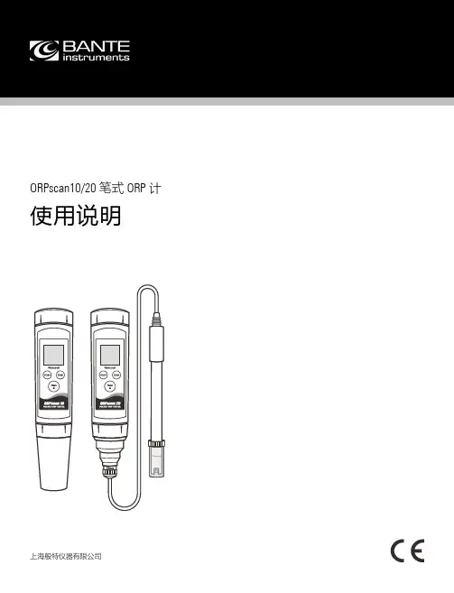
ORPscan10/20笔式ORP 计使用说明上海般特仪器有限公司1 I综述感谢您选择般特仪器的ORPscan 系列笔式ORP 计。
这本用户手册循序渐进地描述了测量仪的各项功能与特征。
使用前,请仔细阅读。
安装电池 1. 拧下测量仪前端的电极固定圈,取下电极(或BNC 连接器)。
2. 将2节AAA 电池插入电池仓,注意极性。
3. 对准插槽,将电极(或BNC 连接器)缓慢推入主机,顺时 针拧入电极固定圈直至锁紧。
按键 按键 功能 • 开关测量仪 • 锁定或解锁测量 • 退出校准、设置并且返回测量 • 开始校准 • 按住键进入设置菜单• 选择一个选项• 确认校准、设置或显示的选项 显示 图标 描述MEAS 表示正在测量CAL 表示正在校准SETUP 表示正在设置选项或数值使用前ORPscan10取下电极保护帽(与半透明盖),如果一些盐晶体沉积在电极壁,用自来水冲洗以清除沉积物。
如果铂金传感器已干燥,将电极浸入电极浸泡液约30分钟。
ORPscan20取出携带箱内的ORP 电极,将BNC 连接器插入测量仪的连接器座,顺时针旋转并锁紧。
开关测量仪• 按住Meas 键约5秒开机。
• 按住Meas 键关机。
如果8分钟内无按键操作,测量仪将自动关机以节省电能。
电极浸泡液I 2设置菜单ORPscan 系列笔式ORP 计内含一个简洁的设置菜单用于自定义功能选项以满足使用偏好,下表描述了各菜单项的功能。
菜单项 选项与描述 自动锁定 设置是否自动判别并锁定测量终点。
启用禁用(默认) 自动关机 设置8分钟内无按键操作是否自动关机。
启用(默认) 禁用重置测量仪 设置是否删除校准数据并且恢复测量仪至工厂默认设置。
注意,一旦启用,测量仪必须重新校准。
启用禁用(默认) 设置默认选项 1. 在测量模式,按住Cal 键进入设置菜单。
2. 如有需要,再次按Cal 键选择一个选项。
3. 按Enter 键保存当前选项,屏幕显示下一个菜单项。
FX-1000中文简介
轮胎压机 批运转
压力 温度
串行通信
批记录 开始/停止
电磁阀 温度
电磁控制
PLC
调节阀
温度调节器
规格
标准规格
一般规格 ●构造 安装方法:
仪表板厚度: 前面板:
嵌入式仪表板安装 (垂直仪表盘) 允许向后最大倾斜30度安装,左右水平 2 to 26 mm 防滴防尘:符合IEC529-IP65。并排紧密安装除外
测量环境试验数据,以简洁易懂的方式显示并记录多种数据。 -多种输入类型可供选择(通用输入) -自动计算出干球温度和湿球温度的相对湿度。(/M1,/PM1,/PWR1选配件) -运算结果能够与温度和湿度,及其他参数(压力,电流)混合记录
干球温度 湿球温度
轮胎制造(加硫工序)的温度与压力管理
测量并记录模具的温度与压力。
道选择 ● 测量/显示精度:
±0.05% of rdg (直流电压), ±0.15% of rdg (热电偶, 热电阻)
数据安全保证
● 400MB 大内存 ● 最大2GB CF卡数据保存 (选配件) ● USB接口支持(选配件) ● 二进制数据保存 ● 网络化双重数据备份
多通道测量/记录
支持所有输入类型的通用输入
显示直观,操作简单
● 5.7英寸宽视角高分辨TFT彩色液晶屏 ● 曲 线、 数 字、 棒 图、 总 览、 报 警、
历史画面显示 ● 通过网络在PC机显示本体画面 ● 多功能方向键操作ー
丰富的测量类型, 卓越的性能
● mV, TC, RTD, DI万能输入 ● 1s, 125ms测量周期(最短) ● 2CH, 4CH, 6CH, 8CH, 10CH, 12CH多通
测量/显示精度:
横河G10G20无纸记录仪
横河G10G20无纸记录仪1.大屏幕显示:G10G20装备了高分辨率、高亮度的液晶显示屏,可以清晰地展示各种测量数据,操作界面简单直观。
2.多通道输入:G10G20支持多达100个输入通道,可以接收多种类型的传感器信号,包括温度、压力、流量等,满足了工业现场对多因素监测的需求。
3.高精度测量:横河G10G20采用了先进的传感器和测量技术,具有高精度和稳定性,可信度高。
4.大容量存储:G10G20内置大容量存储器,可以保存大量的测量数据,不需要使用传统的纸质记录表格,简化了数据管理和归档的过程。
5.多种通信接口:G10G20支持多种通信接口,包括USB、以太网等,方便数据的导入和导出,实现联网与远程控制。
6.自动报警功能:G10G20可以设置上下限报警值,当测量数据超出预设范围时,系统会发出警报,提示用户进行相应的措施。
1.实时监测与记录:G10G20能够实时监测工业过程中的各种测量数据,并将数据准确记录下来。
2. 数据分析与导出:G10 G20具备强大的数据分析能力,可以对历史数据进行图表展示和趋势分析,帮助用户更好地理解工业过程的变化规律。
同时,G10 G20还可以将数据导出为Excel、PDF等格式,方便用户进行数据报表的生成和共享。
3. 实时报警与远程通知:G10 G20可以根据预设的报警条件,实时监测数据,并在触发报警时发出警报信号,提醒用户采取相应的应急措施。
同时,G10 G20还可以通过手机短信、Email等方式将报警信息发送给相关人员,实现远程监控与通知。
4.数据查询与回溯:G10G20内置了强大的数据查询与回溯功能,用户可以通过设定的时间范围和关键字进行数据的检索和回放,方便用户快速找到需要的数据并进行分析。
1.温度监控:G10G20可以接收温度传感器的信号,并实时监测和记录温度数据,用于工业过程中的温度控制和安全监测。
2.压力监测:G10G20可以接收压力传感器的信号,并实时监测和记录压力数据,用于工业设备的运行状态监测。
横河PX8000示波器功率仪
变频器电机测试中的一个常见问题就是环境噪 声,这意味着测试开始之前测试值就已经不为 零了。通过偏置功能,PX8000可以消除这样的 影响并隔离特定的输入,以便于测试和分析。
逆变升压电路中的电 抗器损耗测量
总述
电抗器由电磁芯和线圈组成,位置在变频器之前,作用 是过滤噪声和提高电压电平。电气工程师要关注的重点 是如何降低整个变频器系统的功率损耗,同时电抗器性 能也是他们的兴趣所在。
详细瞬态分析
通过精确定义开始和结束(Start/Stop)光标,PX8000可 以测量开始和结束之间的所有功率波形参数。
趋势运算
PX8000拥有均方根(RMS)、平均功率等内置运算功能, 可以显示周期功率趋势图。
去延迟补偿
PX8000的去延迟功能可以消除可能由传感器或输入特性 引起的电流信号和电压信号之间的偏置。
Power meets precision
世界各地的研发团队都在努力接受功率测量对新精度 水平的要求。由于微处理器控制的普及和减少能源消 耗的持续压力,电气和电子工程之间的界限越来越模 糊,如今业界急需一个新的测量类别⸺混合测量。
传统功率测量仪器不能提供准确的时间测量,而示波 器又不是专为测量功率而设计的仪器。作为世界上首 台示波功率仪,PX8000为功率测量领域带来了示波 器风格的瞬态测量。
横河功率分析仪系列
PX8000是广受业界好评的横河功率分析仪系列中的全新旗 舰产品。横河早在20世纪60年代就设计了第一台功率测量 仪器。此后,横河功率分析仪一直在可持续工业发展中发 挥着重要作用。
isoPROTM – 首创测量技术
PX8000采用了横河isoPROTM技术,可提供业界领先的绝 缘性能和最高速度。由于设计时考虑到节能应用的目的, isoPRO核心技术为高电压、大电流、高频率等工作条件下 变频器的高效评价提供了性能保障。
横河DL850E示波器记录仪
CAN/CAN FD总线、LIN总线和SENT监视
使用示波记录仪解析CAN/CAN FD总线、LIN总线或SENT信号,将 发动机温度、车辆速度和制动踏板定位等物理数据信息显示为模拟 波形后,再与每个实际的传感器数据作比较。
解码
模拟传感器波形 CAN/CAN FD物理层波形
CAN/CAN FD数据趋势1 CAN/CAN FD数据趋势2
光标类型
水平、垂直、标记、角度(仅限 T-Y波形显示)、H&V
用户自定义运算 (/G2选件)
通过用户自定义运算,可以将微积分、数字滤波等一系列 函数运算功能组合成公式。此外,也可以用两个FFT窗口执 行各种FFT分析。在振(震)动测试中,即使同时测量其他信 号,也可以对异常振动做出轻松评价。
加速度传感器
为耐久性测试提供值得信赖的平台 可连续记录200天,测量结果保存至 大容量采集内存、内置硬盘和/或计算 机硬盘。
缩短故障查找时间 强大的触发功能可与双捕获、历史存 储等特色功能搭配使用,可捕捉长时 间测量中的瞬态信号。
功率运、 功率因数、积分功率和谐波等,显示 趋势波形。
采样率 1MS/s 200kS/s 100kS/s 50kS/s
使用1CH时 10小时 2.5天 5天 10天
使用16CH时 – –
10小时 20小时
10kS/s 1kS/s
50天 200天*1
5天 50天
*1: 实时硬盘记录时间最长200天。 *2: 使用720254模块时。 *3: 选择/M2选件时,最长时间取决于存储长度。
符号编辑器是一款软件工具,用于定义在CAN/CAN FD或LIN总线数据帧中哪些物理值要以趋势波形数据形式显示到示波记录 仪上。它可以加载安装于汽车上的网络定义文件(CAN DBC、LIN LDF)。