建筑外文文献及翻译
土木工程建筑外文翻译外文文献英文文献欧洲桥梁研究
Bridge research in EuropeA brief outline is given of the development of the European Union, together with the research platform in Europe. The special case of post-tensioned bridges in the UK is discussed. In order to illustrate the type of European research being undertaken, an example is given from the University of Edinburgh portfolio: relating to the identification of voids in post-tensioned concrete bridges using digital impulse radar.IntroductionThe challenge in any research arena is to harness the findings of different research groups to identify a coherent mass of data, which enables research and practice to be better focused. A particular challenge exists with respect to Europe where language barriers are inevitably very significant. The European Community was formed in the 1960s based upon a political will within continental Europe to avoid the European civil wars, which developed into World War 2 from 1939 to 1945. The strong political motivation formed the original community of which Britain was not a member. Many of the continental countries saw Britain’s interest as being purely economic. The 1970s saw Britain joining what was then the European Economic Community (EEC) and the 1990s has seen the widening of the community to a European Union, EU, with certain political goals together with the objective of a common European currency.Notwithstanding these financial and political developments, civil engineering and bridge engineering in particular have found great difficulty in forming any kind of common thread. Indeed the educational systems for University training are quite different between Britain and the European continental countries. The formation of the EU funding schemes —e.g. Socrates, Brite Euram and other programs have helped significantly. The Socrates scheme is based upon the exchange of students between Universities in different member states. The Brite Euram scheme has involved technical research grants given to consortia of academics and industrial partners within a number of the states— a Brite Euram bid would normally be led by an industrialist.In terms of dissemination of knowledge, two quite different strands appear to have emerged. The UK and the USA have concentrated primarily upon disseminating basic research in refereed journal publications: ASCE, ICE and other journals. Whereas the continental Europeans have frequently disseminated basic research atconferences where the circulation of the proceedings is restricted.Additionally, language barriers have proved to be very difficult to break down. In countries where English is a strong second language there has been enthusiastic participation in international conferences based within continental Europe —e.g. Germany, Italy, Belgium, The Netherlands and Switzerland. However, countries where English is not a strong second language have been hesitant participants }—e.g. France.European researchExamples of research relating to bridges in Europe can be divided into three types of structure:Masonry arch bridgesBritain has the largest stock of masonry arch bridges. In certain regions of the UK up to 60% of the road bridges are historic stone masonry arch bridges originally constructed for horse drawn traffic. This is less common in other parts of Europe as many of these bridges were destroyed during World War 2.Concrete bridgesA large stock of concrete bridges was constructed during the 1950s, 1960s and 1970s. At the time, these structures were seen as maintenance free. Europe also has a large number of post-tensioned concrete bridges with steel tendon ducts preventing radar inspection. This is a particular problem in France and the UK.Steel bridgesSteel bridges went out of fashion in the UK due to their need for maintenance as perceived in the 1960s and 1970s. However, they have been used for long span and rail bridges, and they are now returning to fashion for motorway widening schemes in the UK.Research activity in EuropeIt gives an indication certain areas of expertise and work being undertaken in Europe, but is by no means exhaustive.In order to illustrate the type of European research being undertaken, an example is given from the University of Edinburgh portfolio. The example relates to the identification of voids in post-tensioned concrete bridges, using digital impulse radar.Post-tensioned concrete rail bridge analysisOve Arup and Partners carried out an inspection and assessment of the superstructure of a 160 m long post-tensioned, segmental railway bridge inManchester to determine its load-carrying capacity prior to a transfer of ownership, for use in the Metrolink light rail system..Particular attention was paid to the integrity of its post-tensioned steel elements. Physical inspection, non-destructive radar testing and other exploratory methods were used to investigate for possible weaknesses in the bridge.Since the sudden collapse of Ynys-y-Gwas Bridge in Wales, UK in 1985, there has been concern about the long-term integrity of segmental, post-tensioned concrete bridges which may be prone to ‘brittle’ failure without warning. The corrosion protection of the post-tensioned steel cables, where they pass through joints between the segments, has been identified as a major factor affecting the long-term durability and consequent strength of this type of bridge. The identification of voids in grouted tendon ducts at vulnerable positions is recognized as an important step in the detection of such corrosion.Description of bridgeGeneral arrangementBesses o’ th’ Barn Bridge is a 160 m long, three span, segmental, post-tensioned concrete railway bridge built in 1969. The main span of 90 m crosses over both the M62 motorway and A665 Bury to Prestwick Road. Minimum headroom is 5.18 m from the A665 and the M62 is cleared by approx 12.5 m.The superstructure consists of a central hollow trapezoidal concrete box section 6.7 m high and 4 m wide. The majority of the south and central spans are constructed using 1.27 m long pre-cast concrete trapezoidal box units, post-tensioned together. This box section supports the in site concrete transverse cantilever slabs at bottom flange level, which carry the rail tracks and ballast.The center and south span sections are of post-tensioned construction. These post-tensioned sections have five types of pre-stressing:1. Longitudinal tendons in grouted ducts within the top and bottom flanges.2. Longitudinal internal draped tendons located alongside the webs. These are deflected at internal diaphragm positions and are encased in in site concrete.3. Longitudinal macalloy bars in the transverse cantilever slabs in the central span .4. Vertical macalloy bars in the 229 mm wide webs to enhance shear capacity.5. Transverse macalloy bars through the bottom flange to support the transverse cantilever slabs.Segmental constructionThe pre-cast segmental system of construction used for the south and center span sections was an alternative method proposed by the contractor. Current thinking suggests that such a form of construction can lead to ‘brittle’ failure of the entire structure without warning due to corrosion of tendons across a construction joint,The original design concept had been for in site concrete construction.Inspection and assessmentInspectionInspection work was undertaken in a number of phases and was linked with the testing required for the structure. The initial inspections recorded a number of visible problems including:Defective waterproofing on the exposed surface of the top flange.Water trapped in the internal space of the hollow box with depths up to 300 mm.Various drainage problems at joints and abutments.Longitudinal cracking of the exposed soffit of the central span.Longitudinal cracking on sides of the top flange of the pre-stressed sections.Widespread sapling on some in site concrete surfaces with exposed rusting reinforcement.AssessmentThe subject of an earlier paper, the objectives of the assessment were:Estimate the present load-carrying capacity.Identify any structural deficiencies in the original design.Determine reasons for existing problems identified by the inspection.Conclusion to the inspection and assessmentFollowing the inspection and the analytical assessment one major element of doubt still existed. This concerned the condition of the embedded pre-stressing wires, strands, cables or bars. For the purpose of structural analysis these elements、had been assumed to be sound. However, due to the very high forces involved,、a risk to the structure, caused by corrosion to these primary elements, was identified.The initial recommendations which completed the first phase of the assessment were:1. Carry out detailed material testing to determine the condition of hidden structural elements, in particularthe grouted post-tensioned steel cables.2. Conduct concrete durability tests.3. Undertake repairs to defective waterproofing and surface defects in concrete.Testing proceduresNon-destructi v e radar testingDuring the first phase investigation at a joint between pre-cast deck segments the observation of a void in a post-tensioned cable duct gave rise to serious concern about corrosion and the integrity of the pre-stress. However, the extent of this problem was extremely difficult to determine. The bridge contains 93 joints with an average of 24 cables passing through each joint, i.e. there were approx. 2200 positions where investigations could be carried out. A typical section through such a joint is that the 24 draped tendons within the spine did not give rise to concern because these were protected by in site concrete poured without joints after the cables had been stressed.As it was clearly impractical to consider physically exposing all tendon/joint intersections, radar was used to investigate a large numbers of tendons and hence locate duct voids within a modest timescale. It was fortunate that the corrugated steel ducts around the tendons were discontinuous through the joints which allowed the radar to detect the tendons and voids. The problem, however, was still highly complex due to the high density of other steel elements which could interfere with the radar signals and the fact that the area of interest was at most 102 mm wide and embedded between 150 mm and 800 mm deep in thick concrete slabs.Trial radar investigations.Three companies were invited to visit the bridge and conduct a trial investigation. One company decided not to proceed. The remaining two were given 2 weeks to mobilize, test and report. Their results were then compared with physical explorations.To make the comparisons, observation holes were drilled vertically downwards into the ducts at a selection of 10 locations which included several where voids were predicted and several where the ducts were predicted to be fully grouted. A 25-mm diameter hole was required in order to facilitate use of the chosen horoscope. The results from the University of Edinburgh yielded an accuracy of around 60%.Main radar sur v ey, horoscope verification of v oids.Having completed a radar survey of the total structure, a baroscopic was then used to investigate all predicted voids and in more than 60% of cases this gave a clear confirmation of the radar findings. In several other cases some evidence ofhoneycombing in the in site stitch concrete above the duct was found.When viewing voids through the baroscopic, however, it proved impossible to determine their actual size or how far they extended along the tendon ducts although they only appeared to occupy less than the top 25% of the duct diameter. Most of these voids, in fact, were smaller than the diameter of the flexible baroscopic being used (approximately 9 mm) and were seen between the horizontal top surface of the grout and the curved upper limit of the duct. In a very few cases the tops of the pre-stressing strands were visible above the grout but no sign of any trapped water was seen. It was not possible, using the baroscopic, to see whether those cables were corroded.Digital radar testingThe test method involved exciting the joints using radio frequency radar antenna: 1 GHz, 900 MHz and 500 MHz. The highest frequency gives the highest resolution but has shallow depth penetration in the concrete. The lowest frequency gives the greatest depth penetration but yields lower resolution.The data collected on the radar sweeps were recorded on a GSSI SIR System 10. This system involves radar pulsing and recording. The data from the antenna is transformed from an analogue signal to a digital signal using a 16-bit analogue digital converter giving a very high resolution for subsequent data processing. The data is displayed on site on a high-resolution color monitor. Following visual inspection it is then stored digitally on a 2.3-gigabyte tape for subsequent analysis and signal processing. The tape first of all records a ‘header’ noting the digital radar settings together with the trace number prior to recording the actual data. When the data is played back, one is able to clearly identify all the relevant settings —making for accurate and reliable data reproduction.At particular locations along the traces, the trace was marked using a marker switch on the recording unit or the antenna.All the digital records were subsequently downloaded at the University’s NDT laboratory on to a micro-computer.(The raw data prior to processing consumed 35 megabytes of digital data.)Post-processing was undertaken using sophisticated signal processing software. Techniques available for the analysis include changing the color transform and changing the scales from linear to a skewed distribution in order to highlight、突出certain features. Also, the color transforms could be changed to highlight phase changes. In addition to these color transform facilities, sophisticatedhorizontal and vertical filtering procedures are available. Using a large screen monitor it is possible to display in split screens the raw data and the transformed processed data. Thus one is able to get an accurate indication of the processing which has taken place. The computer screen displays the time domain calibrations of the reflected signals on the vertical axis.A further facility of the software was the ability to display the individual radar pulses as time domain wiggle plots. This was a particularly valuable feature when looking at individual records in the vicinity of the tendons.Interpretation of findingsA full analysis of findings is given elsewhere, Essentially the digitized radar plots were transformed to color line scans and where double phase shifts were identified in the joints, then voiding was diagnosed.Conclusions1. An outline of the bridge research platform in Europe is given.2. The use of impulse radar has contributed considerably to the level of confidence in the assessment of the Besses o’ th’ Barn Rail Bridge.3. The radar investigations revealed extensive voiding within the post-tensioned cable ducts. However, no sign of corrosion on the stressing wires had been found except for the very first investigation.欧洲桥梁研究欧洲联盟共同的研究平台诞生于欧洲联盟。
建筑结构设计中英文对照外文翻译文献
中英文对照外文翻译(文档含英文原文和中文翻译)Create and comprehensive technology in the structure globaldesign of the buildingThe 21st century will be the era that many kinds of disciplines technology coexists , it will form the enormous motive force of promoting the development of building , the building is more and more important too in global design, the architect must seize the opportunity , give full play to the architect's leading role, preside over every building engineering design well. Building there is the global design concept not new of architectural design,characteristic of it for in an all-round way each element not correlated with building- there aren't external environment condition, building , technical equipment,etc. work in coordination with, and create the premium building with the comprehensive new technology to combine together.The premium building is created, must consider sustainable development , namely future requirement , in other words, how save natural resources as much as possible, how about protect the environment that the mankind depends on for existence, how construct through high-quality between architectural design and building, in order to reduce building equipment use quantity andreduce whole expenses of project.The comprehensive new technology is to give full play to the technological specialty of every discipline , create and use the new technology, and with outside space , dimension of the building , working in coordination with in an all-round way the building component, thus reduce equipment investment and operate the expenses.Each success , building of engineering construction condense collective intelligence and strength; It is intelligence and expectation that an architect pays that the building is created; The engineering design of the building is that architecture , structure , equipment speciality compose hardships and strength happenning; It is the diligent and sweat paid in design and operation , installation , management that the construction work is built up .The initial stage of the 1990s, our understanding that the concept of global design is a bit elementary , conscientious to with making some jobs in engineering design unconsciously , make some harvest. This text Hangzhou city industrial and commercial bank financial comprehensive building and Hangzhou city Bank of Communications financial building two building , group of " scientific and technological progress second prize " speak of from person who obtain emphatically, expound the fact global design - comprehensive technology that building create its , for reach global design outstanding architect in two engineering design, have served as the creator and persons who cooperate while every stage design and even building are built completely.Two projects come into operation for more than 4 years formally , run and coordinate , good wholly , reach the anticipated result, accepted and appreciated by the masses, obtain various kinds of honor .outstanding to design award , progress prize in science and technology , project quality bonus , local top ten view , best model image award ,etc., the ones that do not give to the architect and engineers without one are gratified and proud. The building is created Emphasizing the era for global design of the building, the architects' creation idea and design method should be broken through to some extent, creation inspirations is it set up in analysis , building of global design , synthesize more to burst out and at the foundation that appraise, learn and improve the integration capability exactly designed in building , possess the new knowledge system and thinking method , merge multi-disciplinary technology. We have used the new design idea in above-mentioned projects, have emphasized the globality created in building .Is it is it act as so as to explain to conceive to create two design overview and building of construction work these now.1) The financial comprehensive building of industrial and commercial bank of HangZhou,belong to the comprehensive building, with the whole construction area of 39,000 square meters, main building total height 84, 22, skirt 4 of room, some 6 storeys, 2 storeys of basements.Design overall thinking break through of our country bank building traditional design mode - seal , deep and serious , stern , form first-class function, create of multi-functional type , the style of opening , architecture integrated with the mode of the international commercial bank.The model of the building is free and easy, opened, physique was made up by the hyperboloid, the main building presented " the curved surface surrounded southwards ", skirt room presents " the curved surface surrounded northwards ", the two surround but become intension of " gathering the treasure ".Building flourishing upwards, elevation is it adopt large area solid granite wall to design, the belt aluminium alloy curtain wall of the large area and some glass curtain walls, and interweave the three into powerful and vigorous whole , chase through model and entity wall layer bring together , form concise , tall and straight , upward tendency of working up successively, have distinct and unique distinctions.Building level and indoor space are designed into a multi-functional type and style of opening, opening, negotiate , the official working , meeting , receiving , be healthy and blissful , visit combining together. Spacious and bright two storeys open in the hall unifiedly in the Italian marble pale yellow tone , in addition, the escalator , fountain , light set off, make the space seem very magnificent , graceful and sincere. Intelligent computer network center, getting open and intelligent to handle official business space and all related house distribute in all floor reasonably. Top floor round visit layer, lift all of Room visit layer , can have a panoramic view of the scenery of the West Lake , fully enjoy the warmth of the nature. 2) The financial building of Bank of Communications of Hangzhou, belong to the purely financial office block, with the whole construction area of 19,000 square meters, the total height of the building is 39.9 meters, 13 storeys on the ground, the 2nd Floor. Live in building degree high than it around location , designer have unique architectural appearance of style architectural design this specially, its elevation is designed into a new classical form , the building base adopts the rough granite, show rich capability , top is it burn granite and verticality bar and some form aluminum windows make up as the veneer to adopt, represent the building noble and refined , serious personality of the bank.While creating in above-mentioned two items, besides portraying the shape of the building and indoor space and outside environment minister and blending meticulously, in order to achieve the outstanding purpose of global design of the building , the architect , still according to the region and project characteristic, put forward the following requirement to every speciality:(1) Control the total height of the building strictly;(2) It favorable to the intelligent comfortable height of clearances to create; (3) Meet thefloor area of owner's demand;(4)Protect the environment , save the energy , reduce and make the investment;(5) Design meticulously, use and popularize the new technology; (6)Cooperate closely in every speciality, optimization design.Comprehensive technologyThe building should have strong vitality, there must be sustainable development space, there should be abundant intension and comprehensive new technology. Among above-mentioned construction work , have popularized and used the intelligent technology of the building , has not glued and formed the flat roof beam of prestressing force - dull and stereotyped structure technology and flat roof beam structure technology, baseplate temperature mix hole , technology of muscle and base of basement enclose new technology of protecting, computer control STL ice hold cold air conditioner technology, compounding type keeps warm and insulates against heat the technology of the wall , such new technologies as the sectional electricity distribution room ,etc., give architecture global design to add the new vitality of note undoubtedly.1, the intelligent technology of the buildingIn initial stage of the 1990s, the intelligent building was introduced from foreign countries to China only as a kind of concept , computer network standard is it soon , make information communication skeleton of intelligent building to pursue in the world- comprehensive wiring system becomes a kind of trend because of 10BASE-T. In order to make the bank building adapt to the development of the times, the designer does one's utmost to recommend and design the comprehensive wiring system with the leading eyes , this may well be termed the first modernized building which adopted this technical design at that time.(1) Comprehensive wiring system one communication transmission network, it make between speech and data communication apparatus , exchange equipment and other administrative systems link to each other, make the equipment and outside communication network link to each other too. It include external telecommunication connection piece and inside information speech all cable and relevant wiring position of data terminal of workspace of network. The comprehensive wiring system adopts the products of American AT&T Corp.. Connected up the subsystem among the subsystem , management subsystem , arterial subsystem and equipment to make up by workspace subsystem , level.(2) Automated systems of security personnel The monitoring systems of security personnel of the building divide into the public place and control and control two pieces of systemequipment with the national treasury special-purposly synthetically.The special-purpose monitoring systems of security personnel of national treasury are in the national treasury , manage the storehouse on behalf of another , transporting the paper money garage to control strictly, the track record that personnel come in and go out, have and shake the warning sensor to every wall of national treasury , the camera, infrared microwave detector in every relevant rooms, set up the automation of controlling to control.In order to realize building intellectuality, the architect has finished complete indoor environment design, has created the comfortable , high-efficient working environment , having opened up the room internal and external recreation space not of uniform size, namely the green one hits the front yard and roofing, have offered the world had a rest and regulated to people working before automation is equipped all day , hang a design adopt the special building to construct the node in concrete ground , wall at the same time.2, has not glued and formed the flat roof beam of prestressing force- dull and stereotyped structure technology and flat roof beam structure technologyIn order to meet the requirement with high assurance that the architect puts forward , try to reduce the height of structure component in structure speciality, did not glue and form the flat roof beam of prestressing force concrete - dull and stereotyped structure technology and flat roof beam structure technology after adopting.(1) Adopt prestressing force concrete roof beam board structure save than ordinary roof beam board concrete consumption 15%, steel consumption saves 27%, the roof beam reduces 300mm high.(2) Adopt flat roof beam structure save concrete about 10% consumption than ordinary roof beam board, steel consumption saves 6.6%, the roof beam reduces 200mm high.Under building total situation that height does not change , adopt above-mentioned structure can make the whole building increase floor area of a layer , have good economic benefits and social benefit.3, the temperature of the baseplate matches muscle technologyIn basement design , is it is it is it after calculating , take the perimeter to keep the construction technology measure warm to split to resist to go on to baseplate, arrange temperature stress reinforcing bar the middle cancelling , dispose 2 row receives the strength reinforcing bar up and down only, this has not only save the fabrication cost of the project but also met the basement baseplate impervious and resisting the requirement that splits.4, the foundation of the basement encloses and protects the new technology of design and operationAdopt two technological measures in enclosing and protecting a design:(1) Cantilever is it is it hole strength is it adopt form strengthen and mix muscle technology to design to protect to enclose, save the steel and invite 60t, it invests about 280,000 to save.(2) Is it is it protect of of elevation and keep roof beam technology to enclose , is it protect long to reduce 1.5m to enclose all to reduce, keep roof beam mark level on natural ground 1.5m , is it is it protect of lateral pressure receive strength some height to enclose to change, saving 137.9 cubic meters of concrete, steel 16.08t, reduces and invests 304,000 yuan directly through calculating.5, ice hold cold air conditioner technologyIce hold cold air conditioner technology belong to new technology still in our country , it heavy advantage that the electricity moves the peak and operates the expenses sparingly most. In design, is it ice mode adopt some (weight ) hold mode of icing , is it ice refrigeration to be plane utilization ratio high to hold partly to hold, hold cold capacity little , refrigeration plane capacity 30%-45% little than routine air conditioner equipment, one economic effective operational mode.Hold the implementation of the technology of the cold air conditioner in order to cooperate with the ice , has used intelligent technology, having adopted the computer to control in holding and icing the air conditioner system, the main task has five following respects:(1) According to the demand for user's cold load , according to the characteristic of the structure of the electric rate , set up the ice and hold the best operation way of the cold system automatically, reduce the operation expenses of the whole system;(2) Fully utilize and hold the capacity of the cold device, should try one's best to use up all the cold quantity held basically on the same day;(3) Automatic operation state of detection system, ensure ice hold cold system capital equipment normal , safe operation;(4) Automatic record parameter that system operate, display system operate flow chart and type systematic operation parameter report form;(5) Predict future cooling load, confirm the future optimization operation scheme.Ice hold cold air conditioner system test run for some time, indicate control system to be steady , reliable , easy to operate, the system operates the energy-conserving result remarkably.6, the compounding type keeps in the wall warm and insulates against heat To the area of Hangzhou , want heating , climate characteristic of lowering the temperature in summer in winter, is it protect building this structural design person who compound is it insulate against heat the wall to keep warm to enclose specially, namely: Fit up , keep warm , insulate against heat the three not to equal to the body , realize building energy-conservation better.Person who compound is it insulate against heat wall to combine elevation model characteristic , design aluminium board elevation renovation material to keep warm, its structure is: Fill out and build hollow brick in the frame structure, do to hang the American Fluorine carbon coating inferior mere aluminium board outside the hollow brick wall.Aluminium board spoke hot to have high-efficient adiabatic performance to the sun, under the same hot function of solar radiation, because the nature , color of the surface material are different from coarse degree, whether can absorb heat have great difference very , between surface and solar radiation hot absorption system (α ) and material radiation system (Cλ ) is it say to come beyond the difference this. Adopt α and Cλ value little surface material have remarkable result , board α、Cλ value little aluminium have, its α =0.26, Cλ =0.4, light gray face brick α =0.56, Cλ =4.3.Aluminium board for is it hang with having layer under air by hollow brick to do, because aluminium board is it have better radiation transfer to hot terms to put in layer among the atmosphere and air, this structure is playing high-efficient adiabatic function on indoor heating too in winter, so, no matter or can well realize building energy-conservation in winter in summer.7, popularize the technology of sectional electricity distribution roomConsider one layer paves Taxi " gold " value , the total distribution of the building locates the east, set up voltage transformer and low-voltage distribution in the same room in first try in the design, make up sectional electricity distribution room , save transformer substation area greatly , adopt layer assign up and down, mixing the switchyard system entirely after building up and putting into operation, the function is clear , the overall arrangement compactness is rational , the systematic dispatcher is flexible . The technology have to go to to use and already become the model extensively of the design afterwards.ConclusionThe whole mode designed of the building synthetically can raise the adaptability of the building , it will be the inevitable trend , environmental consciousness and awareness of saving energy especially after strengthening are even more important. Developing with the economy , science and technology constantly in our country, more advanced technology and scientific and technical result will be applied to the building , believe firmly that in the near future , more outstanding building global design will appear on the building stage of our country. We will be summarizing, progressing constantly constantly, this is that history gives the great responsibility of architect and engineer.译文:建筑结构整体设计-建筑创作和综合技术21世纪将是多种学科技术并存的时代,它必将形成推动建筑发展的巨大动力,建筑结构整体设计也就越来越重要,建筑师必须把握时机,充分发挥建筑师的主导作用,主持好各项建筑工程设计。
建筑设计中英文对照外文翻译文献
建筑设计中英文对照外文翻译文献On the other hand, there is a significant amount ofliterature in the field of architecture design that is writtenin foreign languages. While it may not be as readily accessible for non-native speakers, there are many benefits to exploring literature in other languages. For example, architects who are fluent in multiple languages can have a broader understanding of different cultural approaches to architecture. By reading literature in foreign languages, architects can gain insights into design concepts and practices that may not be covered in English-language sources. This can lead to a more diverse and innovative approach to design.However, one challenge with accessing literature in foreign languages is the accuracy of translations. Architecture is a technical field with specific terminology, and it is important to ensure that translations accurately convey the intended meaning. In some cases, the translation of technical terms and concepts may not accurately convey their full meaning, which can lead to misunderstandings or confusion. Architects who rely on translated literature should be cautious and ensure they verify the accuracy of the translations with experts in the field.Despite these challenges, it is essential for architects to explore literature in multiple languages to stay informed and to gain a global perspective on architecture design. By consideringboth English and foreign language translated literature, architects can access a wider range of resources and insights. Additionally, architects should consider collaborating with colleagues who are fluent in different languages to ensure accurate translation and interpretation of foreign language sources.In conclusion, architecture design is a field that benefits from accessing literature in multiple languages. English provides a wealth of resources and is the global language of academia. However, architects who can access and read literature in foreign languages can gain new perspectives and insights into different cultural approaches to design. While caution should be taken to verify the accuracy of translations, architects should explore literature in multiple languages to broaden their understanding and enhance their creative problem-solving skills.。
建筑施工质量管理体系外文翻译参考文献
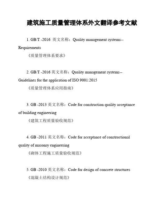
建筑施工质量管理体系外文翻译参考文献1. GB/T -2016 英文名称:Quality management systems--Requirements《质量管理体系要求》2. GB/T -2016 英文名称:Quality management systems--Guidelines for the application of ISO 9001:2015《质量管理体系应用指南》3. GB -2013 英文名称:Code for construction quality acceptance of building engineering《建筑工程质量验收规范》4. GB -2011 英文名称:Code for acceptance of constructional quality of masonry engineering《砌体工程施工质量验收规范》5. GB -2010 英文名称:Code for design of concrete structures《混凝土结构设计规范》6. GB -2013 英文名称:Standard for building drawing standardization《建筑施工图件编制规范》7. GB -2001 英文名称:Code for acceptance of construction quality of pile foundation engineering《桩基工程施工质量验收规范》8. /T 11-2017 英文名称:Technical specification for concrete structure of tall building《高层建筑混凝土结构技术规范》9. 63-2013 英文名称:Technical specification for strengthening of building structures using carbon fiber reinforced plastics 《建筑结构加固碳纤维布增强复合材料技术规范》10. 81-2002 英文名称:Technical specification for application of sprayed mortar in building construction and acceptance of quality 《建筑喷涂砂浆工程施工及质量验收技术规定》。
建筑设计外文翻译文献
建筑设计外文翻译文献(文档含中英文对照即英文原文和中文翻译)外文:Structural Design of Reinforced Concrete Sloping Roof Abstract: This paper point out common mistakes and problems in actual engineering design according immediately poured reinforced concrete sloping roof especially common residential structure.It brings out layout and design concept use folded plate and arch shell structure in order to reduction or elimination beam and column Layout to reduce costs and expand use function for user of garret . The paper also discussed the need to open the roof holes, windows, and with other design with complex forms . The corresponding simple approximate calculation method and the structure treatment also described in this paper.Keywords : sloping roof;folded plate; along plane load;vertical plane load1. IntroductionIn recent years, reinforced concrete slope of the roof has been very common seen, the correct method of it’s design need establish urgently It’s target is to abolish or reduce the roof beams and columns, to obtain big room and make the roof plate "clean ". This not only benefits tructure specialty itself but also to the design of the building professionals to develop new field, and ultimately to allow users, property developers benefited,and so it has far-reaching significance.In the common practice engineering practice, a designer in the calculation of the mechanical model often referred sloping roof as vertical sloping roof under the projection plane Beam, or take level ridge, ramps ridge contour as a framework and increase unnecessary beam and tilt column . In fact ,the stress is similar between General square planar housing, double slope, multi-slope roof and arch, shell.Ping and oblique ridge are folded plate like “A”, whether layout beams and columns, its ridge line of the deformation pattern is different from the framework fundamentally. All these method will make the difference between calculation results and real internal structure force. During the construction process, housing backbone, plate bias department template has complex shapes, multi-angle bars overlap, installation and casting is very difficult. These projects are common in construction and is a typical superfluous. Some scholars use the elastic shell theory to analyze folded plate roof、internal force and deformation, reveals the vertical loads law of surrounding the base is neither level rise nor the vertical displacement which to some extent reflects the humps and shell’s features .But assume that boundary conditions which is very different from general engineering actual situation and covered the eaves of a vertical cross-settlement and bottom edge under the fundamental characteristics of rally, so it is not for general engineering design .2. Outlines of MethodsFor most frequently span, the way to cancel the backbone of housing, didn’t add axillary often. But in the periphery under the eaves to the framework need established grid-beam or beams over windows. For long rectangular planar multi-room, multi-column, building professionals in a horizontal layout of the partition wall between each pair of columns and the direction set deep into the same thickness width have possession of a gathering of the rafah beam profiles . Pull beam above has a two-slope roof plate affixed sloping beams expect smaller span. For residential,if it has no needs according construction professional, we will be able to achieve within the household no ceiling beams exposed, see figure 1. Similar lattice theory, this approach emphasizes the use of axial force component effe ct, But is different with the truss because it’s load distribution along the bar not only single but also along the axis of the plate. Generally each plate has force characteristics of folded plate, for bear gravity at the roof, wind, earthquake loads, caused the plate along with the internal force components, each plate is equivalent to strengthen the thin flange beams .Among vertical bearing , it is thin-walled beams anti-edge horizontal component to balance Wang thrust formed by arch shell effect. When plates bear the the vertical component load, each plate is equivalent to a solid edge embedded multilateral bearing plates .The design feature of this method is establish and perfect the sloping roof of the arch, folded plate system Consciously, at top of the roof, using a minimal level of rafah balance beam ramp at the level of thrust.It’s calculation methods can be divided into hand algorithm and computer paper, this paper focus on the hand algorithm.Hand algorithm take the single-slope plate of sloping roof plate as slider , through approximate overall analysis, Simplified boundary conditions of determine plate,solving load effect along level and vertical plane, Internal forces of various linear superposition under the condition of assumption of normal straight, testing stability and integrated reinforcement. The method pursuit of operational, use general engineer familiar calculation steps to address more complex issues.This method is suitable for the framework structure, little modifications also apply to masonrystructure or Frame-wall structure. General arch structure have good anti-seismic performance, if designed properly, the sloping roof will also do so. In this paper the pseudo-static is used to analysis earthquake effects.3. Analysis and Design for Along Plane Effect of LoadsFirst regard to cross profile of figure 1,we analysis equal width rectangular parts of long trapezoidal panels 1、2. as for approximate calculation,it is take plane loads along plane as a constant just like four rectangular plate can be simplified to one-way slab,we take along to long unit width narrow structure as analysis object ,take hinged arch model shown in figure 2.图2a图3a图2b图3b图2c图3cIn Figure 2 the right supports vertical linkage representatives roof beams supporting role, ramps connecting rod on behalf of the board itself thin beam reaction effect which is virtual and approximate equivalent. We would like to calculate two anti-bearing.Because the total pressure of physical project through two plate roof beams and transfer to the ends column, So Anti two numerical difference can be seen as two plates bear along with the plane load and roof beams bear the vertical load pressure. Two Anti power link expressions in Various conditions were given as follows, because the model take units width,so the results is line averageload distribution except it has Focus quality in house.They are bouth represent by N , English leftover subscript s, b, represent the plane along the roof panels and vertical role in the roof beam, g, w, e,represent gravity, air pressure and the level of earthquake separately. d, c, represent distribution of concentrated load or effect separately, In the formula h is thicness of every plate,g is gravitation acceleration, a is roof for the horizontal seismic acceleration value formula, Wk represent the standard value Pressure.m with number footnotesrepresent every numbered ramp the quality distribution per unit area ,m with english footnotes represent quality of per location.as to two symmetrical slopes, the formula can be more concise.Figure 2a represent situation of vertical gravity load ,these formulas as follows:()()'''111100110cos cos 38cos cos cos cos L AL L m L AL N l h l h l m ωαβμααββ-=++ ()()()()'10000000101'100000cos cos 2cos cos 8sin cos 8sin cos cos 8sin cos cos cos l l l l l h m m s h N l l h h l h l μαβωααηαβωμβββαββααβ++-=--++()()()()101101110100001012111cos 2cos cos 2L L L L L L L m LL L L mLL L L L L L N h B hL hL LIμξβαβ⎡⎤⎛⎫⎛⎫⎛⎫--+-+--+⎢⎥ ⎪ ⎪ ⎪⎝⎭⎝⎭⎝⎭⎣⎦=++()()()()()001001110011200101021000110111121cos sin 2sin 2sin cos cos A L h L m LL L L mL L m a L L L L h h L m l m N L L L Ah L L k B h L h L δδββββαβ⎛⎫⎛⎫⎡⎤⎛⎫-+-+--+ ⎪ ⎪ ⎪⎢⎥+⎝⎭⎝⎭⎝⎭⎣⎦=+---++Figure 2b represent situation of bear wind load, these formulas as follows:()()222211122111cos cos cos 8cos cos cos cos wkL h L L S li N a L h h b ωαωββαβα-=++ ()()()()22222001111222212110cos cos cos 11cos cos cos cos sin 5cos sin cos cos sin cos k K L h l w L w w h w h m L N l l AL h L a h L αωαβαβλαβααββββαββ⎡⎤-⎡⎤+⎢⎥=+++-+⎢⎥++⎢⎥⎣⎦⎣⎦Figure 2c represent situation of role of level earthquake, these formulas as follows:()()2222210011022001sin cos sin cos 3sin cos cos cos cos cos a a L h l L L N L h l hl αμβαωαβωβδαβαβδβ+=--+ ()()()()222221011120322222102101sin cos sin cos sin sin sin 3cos 2ln cos 5ln cos cos cos cos a l h m l m L m m m N n s l l l g h l h l δβααβαββββαβαβαβ++=++++ ()()()0010011012110121000111sin cos 2cos 2cos cos cos a a L L m L L L n L L L L L nh L N L l h l h l ββαβαβ⎡⎤⎛⎫⎛⎫-+-+⎢⎥ ⎪ ⎪⎝⎭⎝⎭⎢⎥=+⎢⎥+⎢⎥⎢⎥⎣⎦ ()00000201sin 2cos a a L m L L L h L l θβα⎡⎤⎛⎫-+-⎢⎥ ⎪⎝⎭⎣⎦+()()()2000010121001sin sin cos sin cos sin cos cos 2sin cos a e L m L L L h L m m N l l h βααβαββαβββ⎡⎤⎛⎫-+-⎢⎥ ⎪+⎝⎭⎣⎦=-+ ()()()001001001221111221001sin 1sin cos 2cos 2cos cos cos sin a a L L L L L L m L L L L L h L h l L h l h ωαββαβαββ⎡⎤⎛⎫⎛⎫-+-+⎢⎥ ⎪ ⎪⎝⎭⎝⎭⎢⎥-+⎢⎥+⎢⎥⎢⎥⎣⎦ When vertical seismic calculation required by Seismic Design ParametersIt’s calculate formula generally similar as formula 1 to 4 which only need take gravity g asvertical seismic acceleration a. Above formulas apply to right bearings in figure 2 and also to left when exchange data of two plate.As end triangle of Multi-slope roof ,for simplify and approximate calculation need, we assume two lines distribution load only produced by roof board of several load, effect.now II-II cross-section from figure is took to analysis Long trapezoidal plate two’s end triangle, assuming the structure symmetry approximately, take half of structure to establish model (figure 3). Because linked with the end triangular plate-3 plane has great lateral stiffness ,therefore assume the model leftist stronghold along the central component around which can not be shifted direction. Central Plate vertical stiffness small, in general gravity load of roughly symmetric midpoint only next movement happened possible, Therefore, the model used parallel two-link connection. Wind loading, and the general role of the earthquake in two slope was roughly antisymmetric,so plate model in the central use fixed hinge bearings which allow rotation and transtlateral force to plate 3near the plate beam. Under plate two triangular area is eaves of vertical beams and plates itself along with plane load distribution is functionshown in Figure 1 take the variable x as an argument,assume the distance from position of section II to end part is x 0s so the slope level length is y 0=x 0L 2/L 3,formula 11 to 14 is the value of Vertical triangle of gravity along the x direction arbitrary location of the two load distribution ,where h 3 is Slitting vertical thickness of plate 3.()22001cos 212cos e a a mkxL h x N L sh v l x ββ⎡⎤=-⎢⎥+-⎢⎥⎣⎦ ()211121001sin cos 212cos m kvL h x N l xh x L V βββ⎡⎤=+⎢⎥+-⎢⎥⎣⎦ ()22000002221100max 1123cos L La h L L L L N VL h h l a V L L αγβ⎡⎤⎛⎫=---⎢⎥ ⎪+-⎢⎥⎝⎭⎣⎦ ()22201000112222201001ln 23cos a L L h l L L L n V s xl h v h L x x l L ββ⎡⎤⎛⎫=+-⎢⎥ ⎪+-⎢⎥⎝⎭⎣⎦ As wind load and earthquake effect, sketch could use approximate figure 3b 、3c and use method of structural mechanics to solve But the process is cumbersome and reasonable extent is limited .the wind and earthquake effect is not important compare with the load effect. Moreover,the triangle area is small As approximate calculation, such direct-use rectangular plate slope calculation is more convenient and not obvious waste. The method of solve two load distribution of plate three is same as the solution of Long trapezoidal plate area just make the change of x and y、L2 and L3 in figure 1.The actual profile is part III-III shown in figure 1A B C图4a图4b BDFigure 4 is vertical launch plan and bear load portfolio value of roof ramp shown in Figure 1 to analysis inclined plate and the internal forces of the anti-bearing column . in the figure hypotenuse is oblique roof equal to strengthen frame, Similar wind ramp truss rod and the next edge portfolio, could form the dark truss system ,while long rectangular plate can be seen as part of thin-walled beams, which could also be seen as truss. Therefore, we called roof boarding the plane formed a "thin-walled beam-truss" system, in concrete theory, between the truss and the b eam have no natural divide . it’s no need hand count accurate internal forces and bearing force to such a joint system, Because on the one hand span more, big bending stiffness structure sensitive to the bearing uneven subsidence and have to stay safe reserves; on the other hand it has high cross-section, by increasing reinforced to increase capacity on the cost impact is not significant. Specific algorithm is: Single-ramp calculate by simple cradle, Multi-Span ramp’s bending moment, shear, and supporting anti-edge use the calculate value by the possible maximum numerical control methods, Moment is calculate by simple cradle two sides of supports middle Shear, negative moment and support force calculate according to bearing this continuous, two-hinged, about two span take the largest one. Pin-Pin bearing shear force that is supported by the inter-simple calculate according to simple cradle. But in this method the location of the various internal force’s safety level is uneven expansion, appropriate adjustmen t should be made is late calculation. No mater f the triangular or rectangular part of plate, Thin-plane bending rebar can get by method of moment right boards from the bottom point for the moment distance whichassigned to the eaves or roof. The author believe it has no necessary control number of reinforcement according to smallest beams reinforced rate. On the rim of triangle equivalent to ramp strut can shear entirety. when consider the end is weak can properly reinforced its roof beam below the reinforcement. If shear required stirrup in the rectangular part of thin-walled, should superposition to the beam, generally it’s no need to intentionally imaginary abdominal strengthening reinforcement at rod position.4. Calculation and Design of Pull Beam and Roof BeamsBy column in figure 1 marked calculated value of supporting force and their level of vertical component, horizontal component of the total force multiplied by the cosine of angle. Take column A as example, the first footnotes in R A2 is column number, the first footnotes represent the force generated by the panel two. Their horizontal component balanced by triangle three under the eaves of beams. horizontal component of intermediate support reaction is balanced by the two-level pull beam in deep direction. Then pull beam and above the sloping beams constitutes steel Arch. Because of the existence of antisymmetric load, bilateral role in the anti-power-level components may be inconsistent and pull beam should take the average lag. consider the support impact of uneven settlement, the level pull beam design should take bigger value.Roof beams general under four internal forces: First of the above is levels Rally, The second is axial force generated when oblique roofing in the flange plate plane bending. The third is the vertical load to bear as the roof slab edge beams under bending moment, shear ,like board supported by multi-faceted, Actual force is smaller than bear calculated by one-way plate N b,Fourth is the effect of lateral framework of internal forces .it should linear superposition ,Composite Reinforced, in the situation of weight Load, span and the small dip, checking computations should be took for tension beams cracking, appropriate intensify the section, with fine steel, including the side beams of steel beams rafah terminal should take two meander anchorage,just like letter L With ng as 10d long bends, meander 135 degrees angle and put pull beam intersection with the vertical reinforcement column touting the Meander overcast horn.This paper take model in figure 1 as example, ignore tigers window , 4 sloping roof are 35 o angle, the length of roof slab dimensions are shown in figure 4. Plate unit area quality is 350kg/m2,Overhaul live load is 0.50 kN/m2, Pressure standard of windward side is 0.21 kN/m2, Leeward face is -0.45 kN/m2, Design value of roof horizontal seismic acceleration is 0.1g, Calculate the bearing capacity limit by standardizing, Considered separately with and without seismic load effect of the combination basic design value,we use combination of without earthquake force through compare,Load calculation and analysis results of every position shown in table 1:5. Analysis and Design for Roof of the Vertical Loads Under Sloping RoofSlabs as a Multilateral Support PlateFolded plate structure has character of “unified of borad and frame”: General intersection of each pair of ramps are for mutual support, both sides of the transition line’ plate can be counted dogleg small rotation and transmission, distribution Moment.Under load control which is the role of gravity the two sloping geometry load roughly symmetrical occasions, there is no corner at symmetry capital turning point, Approximate seen as the plate embedded solid edge.if take out a distance by plate of eaves, plate of inside ridge also formation to negative moment,and long roof slabs in the plate sloping beams department and neighbor plate linked together, these all can be approximated as embedded-plate edge to process.For antisymmetric load like horizontal seismic load,the Ping roof should be treated as shear,but it is not control load usually. Plate final design moment value is the status of various unfavorable combination of linear superposition, from the cross-sectional direction plate reinforced by the columns, Reference, balance the require of concrete deep beams of tectonic, upper plate for Moment of negative reinforcement should be reinforced at all or an entire cross-leader, as they also serve as a deep beam distribution lumbartendons or stirrup. plate in the bottom vertical with reinforcement eaves, Negative reinforcementin accordance with their respective calcualte requirements,and it is different after superpositionstirrups requirementBoth sides of "stirrup" in this situation cann’t linked at awnings edge follow shape “U”, can bebent to shape "L" follow upper and down direction,legnth of packs could equal to thickness ofplate.It should enhenced at the node of ramp at the intersection appropriately. It recommended thatuse swagger tectonic shown as in Figure 5 considing simple structure without axillary at thesituation of Cloudy angle without pull. To ensure all reinforced Installing accuracy, Few of therhombus with the supports and rebar stirrups could be added to formed positioning Skeleton atstrengthening reinforced department in the figure, Let two later installed sloping steel plate tie toits lashing,designers should use a three-dimensional geometric method to accurately calculate thediamond stirrups limb edge length and Forming a swagger construction plans6. Calculating and processing of open window and hole in sloping roofAssume the plate in figure 6 has a big hole whose wideth is b ,height is h 0 ,assuming that tungcenter along with the plane bending moment, shear, respectively are M and V through overall calculation, use vierendeel calculation method get about middle cave:1XO MM T τ= 2NR MM T τ=3113312h V V h h =+ 0XO NR M M M V h --= Where I 1、I 2 、I respectively represent upp er and down plate limb’s Section moment of inertia anddouble limbs section moment of inertia.while Edge Moment by hole is:1113I M V b M α=+ 2212I M V b M μ=+not very big by the hole, close to the neutral axis in most cases overall, under the no-hole design of the reinforced the opening hole after the plane can meet the demands by calculation,under the no-hole design of the reinforced the opening hole after the plane can meet the demands by calculation.General tiger win dow’s form prominent roof Facade which a hole had opened up and the other faces a concrete slab closed.when analysis of vertical slab roof slab surface loads ,compare with without windows and roof slabs hole window sheet increased load. profiles of window’s folded plate form make it reduce the bending stiffness compare with without hole roof board, But with the profile hole edge which parallel to the vertical plate is a partial increase in bending stiffness. In the absence of the vertical plate window subordinate legislation should have upturns beam to increase stiffness of the surrounding caves near.in this way i can temporarily ignore the plate stiffness variation acording to the actual load, size and boundary conditions by entities plate to calculate psitive and negative moment and further processing nodes.it should point out that theRoof ramp layout hole edge ideal location is near the plate-bending line, especially in the open side of the window because it was cut down byvertical transmission line of the moment. If the roof slab roof beams department no outward roof then the actual plate-bending force on the line near the roof beam reversed also true, Because of this architects should strive for when determine oosition of tiger position take appropriate care.When pin tung far away from line-bending window wall and roofing in the intersection must bear folded plate and transmission moment, but compare with plate without hole its capacity is weaken surely,and it’s node turn into weak parts. To fill thy judgment and calculation errorstwo panels can be double reinforcement. When the hole is less than line-bending scope should increase negative reinforcement around to keep overall security plate bearing capacity. To ensure steel plate in place accuratly,also should use positioning stirrups and longitudinal reinforcement constitute skeleton similar as figure 5. Hoop end within vertical bars should be strengthen steel and end cave corner should be harvested more than one anchor length to make sure that bottom of the cave 4 tensile stress concentration.7. Stabilize Roof SlopeIn China's V-shaped folded plate structure design norms,the method prevent both sides of theflanges at local instability is limit its generous ratio,This requirement come from the use of isotropic plate buckling theory analysis. In research the flanges outside instability in critical state, the boundary conditions of winglets suppose as freedom outside, fixed interior, pre - and post-hinged on both sides,the situation plates subjected to the bending stress to solve width and height ratio corresponding with the critical pressure compressive stress. When the grade of concreteIs C30,the limit of width and height(b/t)ratio is 47, take 35 as stress non-normative value. Concrete elastic modulus and strength levels is not a linear relationship if use high-strength concrete other study should be taken. In the actual slope roof only a long row to the middle plate bearing plate outside may receive pressure. And here is just the pouringplate affixed roof sloping beams and horizontal pull beam cast together.Have no possible of rollover and foreign rising displacement. norms limited of folded plate span is 21m. roof below and the vertical column spacing generally much smaller it. And the board which into one with roof beams changed boundary conditions of plate, anti-great instability role also very big. For other locations ramp vertical compression edge May also set up the appropriate plate edge beams all these method will receive beyond the norms of redundant safety. Taking into account the plate shear plane, while the vertical direction of the load caused the exit plane effects, Therefore, the grasp of security of caution should cautious. This paper proposed ramp thickness not less than to the short span of 1 / 35 which also conform to design experience of generally confined SLABS, Concrete should graded between C25 and C35 while Steel should I or class II.puter Calculation Method of Local Sloping Roof Structure andOverall ICC of Overall StructureAny calculate software with inclined plate shell modules and the modules bar structural finite element can calculation of competent sloping roof. Shell element of each node have 3 membrane freedom and three panels freedom and can analysis the plane board and internal forces Of out-of-plane effects. However, the current prevalence of certain spatial structure finite element computer program which although have shell model but some are not inclined plate, some not right at the same plane, the stress state and foreign integrated reinforcement are not perfect. Withstructures becoming more diverse, complex and ramp space problems often encountered. Such software should expand its pre - and post-processing functions for conversion of shell element stiffness matrix and loading vector in the direction of freedom and further analysis of ramp space, the space of concrete against stress integrated reinforcement. In a fundamental sense manual method and the finite element method are interchangeable but the result may be very different. As long as layout roof component as this concept,then use the software to calculate can fast, precise, to achieve this goal of this paper.From the eaves to the roof elevation areas, the whole roof of anti-lateral stiffness lower than mutation, quality small than lower,this could not easy to simulate in calculation of whole housing. At the top construction of the seismic as higher-mode response which is also whiplash effect, the earthquake-lateral force may be abnormal and have effect on under layers. Therefore, in the partial hand count roof occasions when take ICC analysis to the overall structure, it proposed roof layer use model of tilt rod ramp support to reduce effect on the overall results distortion.If use software with function of space ramp handling and sloping roof modeling with shell element,all will be wrapped from top to bottom. Top results can be directly used and the distortion of the overall impact would cease to exist.10. Conclusion1)Concrete ramps, side beams in different directions superposition of internal forces, reinforced and ramp stability, the hole limits all to be do in-depth study related this research. Similar typical problems are top floor of structural transformation layer and box-type base box side wall all their research results can be used to adopt.It’s a important method do observation on project; finite element analysis ICC will be more economical, practical and popular. Currently existing completed sloping roof no matter the subjective designers use what kind of assumptions and analysis and whether reinforcement is reasonable as long as the overall structure of the objective reality, create a space folded plate and the arch system that their current work state can be used to summarize and draw upon.2)This structure forms make a new world of design concept of use the top floor and impact on people's living habits.The economic, social benefits it taked will gradually revealed,however it need interaction of architectural and structural professionals and People’s awareness andinformation and even real estate management policies and other support aspects.This method is hard for structure professional,some specific details have no norms to follow at present. This is the challenges sructure staff faced and also the happy exist.references[1]Francis D.K.Ching A Visual Dictionary of Architecture, International Thomson Publishing Inc. 1997.[2]Jiang Fengqing :internal forces of Simply supported two-way pack square plate, Civil Engineering Journal,1982(2)[3]Lai Mingyuan.Zhang Guxin:Deflection and internal forces of Simple peripheral portfolio folded plate roof, Civil Engineering Journal,1992(2)[4] ]Lai Mingyuan: Deflection and internal forces of Simple flattened four folded plate roof slope, Civil Engineering Journal, 1995(1)[5]Li Kaixi.Cui Jia:Local Stability About Yan Beam, Building Structures ,1996(1) [6]user manuals and technical conditions of Multi-storey high-rise building and the space finite element structural analysis and design software SATWE, PKPM CAD department of China Building Research Academy[7]Chen Xinghui.Lin Yuankun: Several calculation problems in the design of V-folded plate roof , Scientific publishing house,1985[8]current building structure norms, China Construction Industry Press,2002译文:钢筋混凝土坡屋顶的结构设计简介:本文对于现浇钢筋混凝土坡屋顶,尤其是常见的住宅结构,指出实际工程中常见的设计错误及问题。
建筑外文文献及翻译(参考模板)
外文原文Study on Human Resource Allocation in Multi-Project Based on the Priority and the Cost of ProjectsLin Jingjing , Zhou GuohuaSchoolofEconomics and management, Southwest Jiao tong University ,610031 ,China Abstract----This paper put forward the a ffecting factors of project’s priority. which is introduced into a multi-objective optimization model for human resource allocation in multi-project environment . The objectives of the model were the minimum cost loss due to the delay of the time limit of the projects and the minimum delay of the project with the highest priority .Then a Genetic Algorithm to solve the model was introduced. Finally, a numerical example was used to testify the feasibility of the model and the algorithm.Index Terms—Genetic Algorithm, Human Resource Allocation, Multi-project’s project’s priority .1.INTRODUCTIONMore and more enterprises are facing the challenge of multi-project management, which has been the focus among researches on project management. In multi-project environment ,the share are competition of resources such as capital , time and human resources often occur .Therefore , it’s critical to schedule projects in order to satisfy the different resource demands and to shorten the projects’ duration time with resources constrained ,as in [1].For many enterprises ,the human resources are the most precious asset .So enterprises should reasonably and effectively allocate each resource , especially the human resource ,in order to shorten the time and cost of projects and to increase the benefits .Some literatures have discussed the resource allocation problem in multi-project environment with resources constrained. Reference [1] designed an iterative algorithm and proposeda mathematical model of the resource-constrained multi-project scheduling .Basedon work breakdown structure (WBS) and Dantzig-Wolfe decomposition method ,a feasible multi-project planning method was illustrated , as in [2] . References [3,4]discussed the resource-constrained project scheduling based on Branch Delimitation method .Reference [5] put forward the framework of human resource allocation in multi-project in Long-term ,medium-term and short-term as well as research and development(R&D) environment .Basedon GPSS language, simulation model of resources allocation was built to get the project’s duration time and resources distribution, as in [6]. Reference [7] solved the engineering project’s resources optimization problem using Genetic Algorithms. These literatures reasonably optimized resources allocation in multi-project, but all had the same prerequisite that the project’s importance is the same to each other .This paper will analyze the effects of project’s priority on human resource allocation ,which is to be introduced into a mathematical model ;finally ,a Genetic Algorithm is used to solve the model.2.EFFECTS OF PROJECTS PRIORITY ON HUMAN RESOUCE ALLOCATIONAND THE AFFECTING FACTORS OF PROJECT’S PRIORITYResource sharing is one of the main characteristics of multi-project management .The allocation of shared resources relates to the efficiency and rationality of the use of resources .When resource conflict occurs ,the resource demand of the project with highest priority should be satisfied first. Only after that, can the projects with lower priority be considered.Based on the idea of project classification management ,this paper classifies the affecting factors of project’s priority into three categories ,as the project’s benefits ,the complexity of project management and technology , and the strategic influence on the enterprise’s future development . The priority weight of the project is the function of the above three categories, as shown in (1).W=f(I,c,s…) (1)Where w refers to project’s priority weight; I refers to the benefits of th e project; c refers to the complexity of the project, including the technology and management; s refers to the influence of the project on enterprise .The bigger the values of the three categories, the higher the priority is.3.HUMAN RESOURCE ALLOCATION MODEL IN MULTI-PROJECTENVIRONMENT3.1Problem DescriptionAccording to the constraint theory, the enterprise should strictly differentiate the bottleneck resources and the non-bottleneck resources to solve the constraint problem of bottleneck resources .This paper will stress on the limited critical human resources being allocated to multi-project with definite duration times and priority.To simplify the problem, we suppose that that three exist several parallel projects and a shared resources storehouse, and the enterprise’s operation only involves one kind of critical human resources. The supply of the critical human resource is limited, which cannot be obtained by hiring or any other ways during a certain period .when resource conflict among parallel projects occurs, we may allocate the human resource to multi-project according to project’s priorities .The allocation of non-critical independent human resources is not considered in this paper, which supposes that the independent resources that each project needs can be satisfied.Engineering projects usually need massive critical skilled human resources in some critical chain ,which cannot be substituted by the other kind of human resources .When the critical chains of projects at the same time during some period, there occur resource conflict and competition .The paper also supposes that the corresponding network planning of various projects have already been established ,and the peaks of each project’s resources demand have been optimized .The delay of the critical chain will affect the whole project’s duration time .3.2 Model HypothesesThe following hypotheses help us to establish a mathematical model:(1)The number of mutually independent projects involved in resourceallocation problem in multi-project is N. Each project is indicated withQ i,while i=1,2, … N.(2)The priority weights of multi-project have been determined ,which arerespectively w1,w 2…w n .(3) The total number of the critical human resources is R ,with r k standingfor each person ,while k=1,2, …,R(4) Δk i = ⎩⎨⎧others toprojectQ rcer humanresou i k 01(5) Resources capturing by several projects begins on time. t E i is theexpected duration time of project I that needs the critical resources tofinish some task after time t ,on the premise that the human resourcesdemand can be satisfied .tAi is the real duration time of project I thatneeds the critical resource to finish some task after time t .(6) According to the contract ,if the delay of the project happens the dailycost loss due to the delay is △c i for pro ject I .According to the project’simportance ,the delay of a project will not only cause the cost loss ,butwill also damage the prestige and status of the enterprise .(while thelatent cost is difficult to quantify ,it isn’t considered in this articletemporarily.)(7) From the hypothesis (5) ,we can know that after time t ,the time-gapbetween the real and expected duration time of project I that needs thecritical resources to finish some task is △t i ,( △t i =t A i -t E i ). For thereexists resources competition, the time –gap is necessarily a positivenumber.(8) According to hypotheses (6) and (7), the total cost loss of project I is C i(C i = △t i * △C i ).(9) The duration time of activities can be expressed by the workload ofactivities divided by the quantity of resources ,which can be indicatedwith following expression of t A i =ηi / R i * ,.In the expression , ηi refersto the workload of projects I during some period ,which is supposed tobe fixed and pre-determined by the project managers on project planningphase ; R i * refers to the number of the critical human resources beingallocated to projects I actually, with the equation Ri * =∑=Rk ki 1δ existing. Due to the resource competition the resourcedemands of projects with higherPriorities may be guarantee, while those projects with lower prioritiesmay not be fully guaranteed. In this situation, the decrease of theresource supply will lead to the increase of the duration time of activitiesand the project, while the workload is fixed.3.3 Optimization ModelBased on the above hypotheses, the resource allocation model inmulti-project environment can be established .Here, the optimizationmodel is :F i =min Z i = min∑∑==Ni i N i Ci 11ω =min i i Ni i N i c t ∆∆∑∑==11ω (2) =min ∑∑==N i i N i 11ω )E i R i ki i t - ⎝⎛∑=1δη i c ∆ 2F =min Z 2=min ()i t ∆=min )E i R i ki i t -⎝⎛∑=1δη (3) Where wj=max(wi) ,(N j i 3,2,1,=∀) (4)Subject to : 0∑∑==≤R k ki N i 11δ=R (5)The model is a multi-objective one .The two objective functions arerespectively to minimize the total cost loss ,which is to conform to theeconomic target ,and to shorten the time delay of the project with highestpriority .The first objective function can only optimize the apparenteconomic cost ;therefore the second objective function will help to makeup this limitation .For the project with highest priority ,time delay will damage not only the economic benefits ,but also the strategy and the prestige of the enterprise .Therefore we should guarantee that the most important project be finished on time or ahead of schedule .4.SOLUTION TO THE MULTI-OBJECTIVE MODEL USING GENETICALGORITHM4.1The multi-objective optimization problem is quite common .Generally ,eachobjective should be optimized in order to get the comprehensive objective optimized .Therefore the weight of each sub-objective should be considered .Reference [8] proposed an improved ant colony algorithm to solve this problem .Supposed that the weights of the two optimizing objectives are αand β ,where α+β=1 .Then the comprehensive goal is F* ,where F*=αF1+βF2.4.2The Principle of Genetic AlgorithmGenetic Algorithm roots from the concepts of natural selection and genetics .It’s a random search technique for global optimization in a complex search space .Because of the parallel nature and less restrictions ,it has the key features of great currency ,fast convergence and easy calculation .Meanwhile ,its search scope is not limited ,so it’s an effective method to solve the resource balancing problem ,as in [9].The main steps of GA in this paper are as follow:(1)EncodingAn integer string is short, direct and efficient .According to thecharacteristics of the model, the human resource can be assigned to be acode object .The string length equals to the total number of humanresources allocated.(2)Choosing the fitness functionThis paper choose the objective function as the foundation of fitnessfunction .To rate the values of the objective function ,the fitness of then-th individual is 1/n。
建筑学Modern-Architecture现代建筑大学毕业论文外文文献翻译及原文
建筑学Modern-Architecture现代建筑⼤学毕业论⽂外⽂⽂献翻译及原⽂毕业设计(论⽂)外⽂⽂献翻译⽂献、资料中⽂题⽬:现代建筑⽂献、资料英⽂题⽬:Modern Architecture⽂献、资料来源:⽂献、资料发表(出版)⽇期:院(部):专业:班级:姓名:学号:指导教师:翻译⽇期: 2017.02.14建筑学毕业设计的外⽂⽂献及译⽂⽂献、资料题⽬:《Advanced Encryption Standard》⽂献、资料发表(出版)⽇期:2004.10.25外⽂⽂献:Modern ArchitectureModern architecture, not to be confused with 'contemporary architecture', is a term given to a number of building styles with similar characteristics, primarily the simplification of form and the elimination of ornament. While the style was conceived early in the 20th century and heavily promoted by a few architects, architectural educators and exhibits, very few Modern buildings were built in the first half of the century. For three decades after the Second World War, however, it became the dominant architectural style for institutional and corporate building.1. OriginsSome historians see the evolution of Modern architecture as a social matter, closely tied to the project of Modernity and hence to the Enlightenment, a result of social and political revolutions.Others see Modern architecture as primarily driven by technological and engineering developments, and it is true that the availability of new building materials such as iron, steel, concrete and glass drove the invention of new building techniques as part of the Industrial Revolution. In 1796, Shrewsbury mill owner Charles Bage first used his ‘fireproof’ design, which relied on cast iron and brick with flag stone floors. Such construction greatly strengthened the structure of mills, which enabled them to accommodate much bigger machines. Due to poor knowledge of iron's properties as a construction material, a number of early mills collapsed. It was not until the early 1830s that Eaton Hodgkinson introduced the section beam, leading to widespread use of iron construction, this kind of austere industrial architecture utterly transformed the landscape of northern Britain, leading to the description, "Dark satanic mills" of places like Manchester and parts of West Yorkshire. The Crystal Palace by Joseph Paxton at the Great Exhibition of 1851 was an early example of iron and glass construction; possibly the best example is the development of the tall steel skyscraper in Chicago around 1890 by William Le Baron Jenney and Louis Sullivan. Early structures to employ concrete as the chief means of architectural expression (rather than for purely utilitarian structure) include Frank Lloyd Wright's Unity Temple, built in 1906 near Chicago, and Rudolf Steiner's Second Goetheanum, built from1926 near Basel, Switzerland.Other historians regard Modernism as a matter of taste, a reaction against eclecticism and the lavish stylistic excesses of Victorian Era and Edwardian Art Nouveau.Whatever the cause, around 1900 a number of architects around the world began developing new architectural solutions to integrate traditional precedents (Gothic, for instance) with new technological possibilities. The work of Louis Sullivan and Frank Lloyd Wright in Chicago, Victor Horta in Brussels, Antoni Gaudi in Barcelona, Otto Wagner in Vienna and Charles Rennie Mackintosh in Glasgow, among many others, can be seen as a common struggle between old and new.2. Modernism as Dominant StyleBy the 1920s the most important figures in Modern architecture had established their reputations. The big three are commonly recognized as Le Corbusier in France, and Ludwig Mies van der Rohe and Walter Gropius in Germany. Mies van der Rohe and Gropius were both directors of the Bauhaus, one of a number of European schools and associations concerned with reconciling craft tradition and industrial technology.Frank Lloyd Wright's career parallels and influences the work of the European modernists, particularly via the Wasmuth Portfolio, but he refused to be categorized with them. Wright was a major influence on both Gropius and van der Rohe, however, as well as on the whole of organic architecture.In 1932 came the important MOMA exhibition, the International Exhibition of Modern Architecture, curated by Philip Johnson. Johnson and collaborator Henry-Russell Hitchcock drew together many distinct threads and trends, identified them as stylistically similar and having a common purpose, and consolidated them into the International Style.This was an important turning point. With World War II the important figures of the Bauhaus fled to the United States, to Chicago, to the Harvard Graduate School of Design, and to Black Mountain College. While Modern architectural design never became a dominant style in single-dwelling residential buildings, in institutional and commercial architecture Modernism became the pre-eminent, and in the schools (for leaders of the profession) the only acceptable, design solution from about 1932 to about 1984.Architects who worked in the international style wanted to break with architectural tradition and design simple, unornamented buildings. The most commonly used materials are glass for the facade, steel for exterior support, and concrete for the floors and interior supports; floor plans were functional and logical. The style became most evident in the design of skyscrapers. Perhaps its most famous manifestations include the United Nations headquarters (Le Corbusier, Oscar Niemeyer, Sir Howard Robertson), the Seagram Building (Ludwig Mies van der Rohe), and Lever House (Skidmore, Owings, and Merrill), all in New York. A prominent residential example is the Lovell House (Richard Neutra) in Los Angeles.Detractors of the international style claim that its stark, uncompromisingly rectangular geometry is dehumanising. Le Corbusier once described buildings as "machines for living", but people are not machines and it was suggested that they do not want to live in machines. Even Philip Johnson admitted he was "bored with the box." Since the early 1980s many architects have deliberately sought to move away from rectilinear designs, towards more eclectic styles. During the middle of the century, some architects began experimenting in organic forms that they felt were more human and accessible. Mid-century modernism, or organic modernism, was very popular, due to its democratic and playful nature. Alvar Aalto and Eero Saarinen were two of the most prolific architects and designers in this movement, which has influenced contemporary modernism.Although there is debate as to when and why the decline of the modern movement occurred, criticism of Modern architecture began in the 1960s on the grounds that it was universal, sterile, elitist and lacked meaning. Its approach had become ossified in a "style" that threatened to degenerate into a set of mannerisms. Siegfried Giedion in the 1961 introduction to his evolving text, Space, Time and Architecture (first written in 1941), could begin "At the moment a certain confusion exists in contemporary architecture, as in painting; a kind of pause, even a kind of exhaustion." At the Metropolitan Museum of Art, a 1961 symposium discussed the question "Modern Architecture: Death or Metamorphosis?" In New York, the coup d'état appeared to materialize in controversy around the Pan Am Building that loomed over Grand Central Station, taking advantage of the modernist real estate concept of "air rights",[1] In criticism by Ada Louise Huxtable and Douglas Haskell it was seen to "sever" the Park Avenue streetscape and "tarnish" the reputations of its consortium of architects: Walter Gropius, Pietro Belluschi and thebuilders Emery Roth & Sons. The rise of postmodernism was attributed to disenchantment with Modern architecture. By the 1980s, postmodern architecture appeared triumphant over modernism, including the temple of the Light of the World, a futuristic design for its time Guadalajara Jalisco La Luz del Mundo Sede International; however, postmodern aesthetics lacked traction and by the mid-1990s, a neo-modern (or hypermodern) architecture had once again established international pre-eminence. As part of this revival, much of the criticism of the modernists has been revisited, refuted, and re-evaluated; and a modernistic idiom once again dominates in institutional and commercial contemporary practice, but must now compete with the revival of traditional architectural design in commercial and institutional architecture; residential design continues to be dominated by a traditional aesthetic.中⽂译⽂:现代建筑现代建筑,不被混淆与'当代建筑' , 是⼀个词给了⼀些建筑风格有类似的特点, 主要的简化形式,消除装饰等. 虽然风格的设想早在20世纪,并⼤量造就了⼀些建筑师、建筑教育家和展品,很少有现代的建筑物,建于20世纪上半叶. 第⼆次⼤战后的三⼗年, 但最终却成为主导建筑风格的机构和公司建设.1起源⼀些历史学家认为进化的现代建筑作为⼀个社会问题, 息息相关的⼯程中的现代性,从⽽影响了启蒙运动,导致社会和政治⾰命.另⼀些⼈认为现代建筑主要是靠技术和⼯程学的发展, 那就是获得新的建筑材料,如钢铁, 混凝⼟和玻璃驱车发明新的建筑技术,它作为⼯业⾰命的⼀部分. 1796年, shrewsbury查尔斯bage⾸先⽤他的'⽕'的设计, 后者则依靠铸铁及砖与⽯材地板. 这些建设⼤⼤加强了结构,使它们能够容纳更⼤的机器. 由于作为建筑材料特性知识缺乏,⼀些早期建筑失败. 直到1830年初,伊顿Hodgkinson预计推出了型钢梁, 导致⼴泛使⽤钢架建设,⼯业结构完全改变了这种窘迫的⾯貌,英国北部领导的描述, "⿊暗魔⿁作坊"的地⽅如曼彻斯特和西约克郡. ⽔晶宫由约瑟夫paxton的重⼤展览, 1851年,是⼀个早期的例⼦,钢铁及玻璃施⼯; 可能是⼀个最好的例⼦,就是1890年由William乐男爵延长和路易沙利⽂在芝加哥附近发展的⾼层钢结构摩天楼. 早期结构采⽤混凝⼟作为⾏政⼿段的建筑表达(⽽⾮纯粹功利结构) ,包括建于1906年在芝加哥附近,劳埃德赖特的统⼀宫, 建于1926年瑞⼠巴塞尔附近的鲁道夫斯坦纳的第⼆哥特堂,.但⽆论原因为何, 约有1900多位建筑师,在世界各地开始制定新的建筑⽅法,将传统的先例(⽐如哥特式)与新的技术相结合的可能性.路易沙利⽂和赖特在芝加哥⼯作,维克多奥尔塔在布鲁塞尔,安东尼⾼迪在巴塞罗那, 奥托⽡格纳和查尔斯景mackintosh格拉斯哥在维也纳,其中之⼀可以看作是⼀个新与旧的共同⽃争.2现代主义风格由1920年代的最重要⼈物,在现代建筑⾥确⽴了⾃⼰的名声. 三个是公认的柯布西耶在法国, 密斯范德尔德罗和⽡尔特格罗⽪乌斯在德国. 密斯范德尔德罗和格罗⽪乌斯为董事的包豪斯, 其中欧洲有不少学校和有关团体学习调和⼯艺和传统⼯业技术.赖特的建筑⽣涯中,也影响了欧洲建筑的现代艺术,特别是通过⽡斯穆特组合但他拒绝被归类与他们. 赖特与格罗⽪乌斯和Van der德罗对整个有机体系有重⼤的影响.在1932年来到的重要moma展览,是现代建筑艺术的国际展览,艺术家菲利普约翰逊. 约翰逊和合作者亨利-罗素阁纠集许多鲜明的线索和趋势, 内容相似,有⼀个共同的⽬的,巩固了他们融⼊国际化风格这是⼀个重要的转折点. 在⼆战的时间包豪斯的代表⼈物逃到美国,芝加哥,到哈佛⼤学设计⿊⼭书院. 当现代建筑设计从未成为主导风格单⼀的住宅楼,在成为现代卓越的体制和商业建筑, 是学校(专业领导)的唯⼀可接受的, 设计解决⽅案,从约1932年⾄约1984年.那些从事国际风格的建筑师想要打破传统建筑和简单的没有装饰的建筑物。
建筑防火中英文对照外文翻译文献
- 1 -中英文对照外文翻译(文档含英文原文和中文翻译)外文文献外文文献: :Designing Against Fire Of BulidingABSTRACT:This paper considers the design of buildings for fire safety. It is found that fire and the associ- ated effects on buildings is significantly different to other forms of loading such as gravity live loads, wind and earthquakes and their respective effects on the building structure. Fire events are derived from the human activities within buildings or from the malfunction of mechanical and electrical equipment provided within buildings to achieve a serviceable environment. It is therefore possible to directly influence the rate of fire starts within buildings by changing human behaviour, improved maintenance and improved design of mechanical and electricalsystems. Furthermore, should a fire develops, it is possible to directly influence the resulting fire severity by the incorporation of fire safety systems such as sprinklers and to provide measures within the building to enable safer egress from the building. The ability to influence the rate of fire starts and the resulting fire severity is unique to the consideration of fire within buildings since other loads such as wind and earthquakes are directly a function of nature. The possible approaches for designing a building for fire safety are presented using an example of a multi-storey building constructed over a railway line. The design of both the transfer structure supporting the building over the railway and the levels above the transfer structure are consideredin the context of current regulatory requirements. The principles and assumptions associ- ated with various approaches are discussed.1 INTRODUCTIONOther papers presented in this series consider the design of buildings for gravity loads, wind and earthquakes.The design of buildings against such load effects is to a large extent covered by engineering based standards referenced by the building regulations. This is not the case, to nearly the same extent, in the case of fire. Rather, it is building regulations such as the Building Code of Australia (BCA) that directly specify most of the requirements for fire safety of buildings with reference being made to Standards such as AS3600 or AS4100 for methods for determining the fire resistance of structural elements.The purpose of this paper is to consider the design of buildings for fire safety from an engineering perspective (as is currently done for other loads such as wind or earthquakes), whilst at the same time,putting such approaches in the context of the current regulatory requirements.At the outset,it needs to be noted that designing a building for fire safety is far more than simply considering the building structure and whether it has sufficient structural adequacy.This is because fires can have a direct influence on occupants via smoke and heat and can grow in size and severity unlike other effects imposed on the building. Notwithstanding these comments, the focus of this paper will be largely on design issues associated with the building structure.Two situations associated with a building are used for the purpose of discussion. The multi-storey office building shown in Figure 1 is supported by a transfer structure that spans over a set of railway tracks. It is assumed that a wide range of rail traffic utilises these tracks including freight and diesel locomotives. The first situation to be considered from a fire safety perspective is the transfer structure.This is termed Situation 1 and the key questions are: what level of fire resistance is required for this transfer structure and how can this be determined? This situation has been chosen since it clearly falls outside the normal regulatory scope of most build-ing regulations. An engineering solution, rather than a prescriptive one is required. The second fire situation (termed Situation 2) corresponds to a fire within the office levels of the building and is covered by building regulations. This situation is chosen because it will enable a discussion of engineering approaches and how these interface with the building regulations regulations––since both engineering and prescriptive solutions are possible.2 UNIQUENESS OF FIRE2.1 Introduction Wind and earthquakes can be considered to b Wind and earthquakes can be considered to be “natural” phenomena o e “natural” phenomena o e “natural” phenomena over which designers ver which designers have no control except perhaps to choose the location of buildings more carefully on the basis of historical records and to design building to resist sufficiently high loads or accelerations for the particular location. Dead and live loads in buildings are the result of gravity. All of these loads are variable and it is possible (although generally unlikely) that the loads may exceed the resistance of the critical structural members resulting in structural failure.The nature and influence of fires in buildings are quite different to those associated with other“loads” to which a building may be subjected to. The essential differences are described in the following sections.2.2 Origin of FireIn most situations (ignoring bush fires), fire originates from human activities within the building or the malfunction of equipment placed within the building to provide a serviceable environment. It follows therefore that it is possible to influence the rate of fire starts by influencing human behaviour, limiting and monitoring human behaviour and improving the design of equipment and its maintenance. This is not the case for the usual loads applied to a building.2.3 Ability to InfluenceSince wind and earthquake are directly functions of nature, it is not possible to influence such events to any extent. One has to anticipate them and design accordingly. It may be possibleto influence the level of live load in a building by conducting audits and placing restrictions on contents. However, in the case of a fire start, there are many factors that can be brought to bear to influence the ultimate size of the fire and its effect within the building. It is known that occupants within a building will often detect a fire and deal with it before it reaches a sig- nificant size. It is estimated that less than one fire in five (Favre, 1996) results in a call to the fire brigade and for fires reported to the fire brigade, the majority will be limited to the room of fire origin. Inoc- cupied spaces, olfactory cues (smell) provide powerful evidence of the presence of even a small fire. The addition of a functional smoke detection system will further improve the likelihood of detection and of action being taken by the occupants.Fire fighting equipment, such as extinguishers and hose reels, is generally provided within buildings for the use of occupants and many organisations provide training for staff in respect ofthe use of such equipment.The growth of a fire can also be limited by automatic extinguishing systems such as sprinklers, which can be designed to have high levels of effectiveness.Fires can also be limited by the fire brigade depending on the size and location of the fire at the time of arrival.2.4 Effects of FireThe structural elements in the vicinity of the fire will experience the effects of heat. The temperatures within the structural elements will increase with time of exposure to the fire, the rate of temperature rise being dictated by the thermal resistance of the structural element and the severity of the fire. The increase in temperatures within a member will result in both thermal expansion and,eventually,a reduction in the structural resistance of the member. Differential thermal expansion will lead to bowing of a member. Significant axial expansion willbe accommodated in steel members by either overall or local buckling or yielding of local- ised regions. These effects will be detrimental for columns but for beams forming part of a floorsystem may assist in the development of other load resisting mechanisms (see Section 4.3.5).With the exception of the development of forces due to restraint of thermal expansion, fire does not impose loads on the structure but rather reduces stiffness and strength. Such effects are not instantaneous but are a function of time and this is different to the effects of loads such as earthquake and wind that are more or less instantaneous.Heating effects associated with a fire will not be significant or the rate of loss of capacity will be slowed if:(a) the fire is extinguished (e.g. an effective sprinkler system)(b) the fire is of insufficient severity –– insufficient fuel, and/or(b) the fire is of insufficient severity(c)the structural elements have sufficient thermal mass and/or insulation to slow the rise in internal temperatureFire protection measures such as providing sufficient axis distance and dimensions for concrete elements, and sufficient insulation thickness for steel elements are examples of (c). These are illustrated in Figure 2.The two situations described in the introduction are now considered.3 FIRE WITHIN BUILDINGS3.1 Fire Safety ConsiderationsThe implications of fire within the occupied parts of the office building (Figure 1) (Situation 2) are now considered. Fire statistics for office buildings show that about one fatality is expected in an office building for every 1000 fires reported to the fire brigade. This is an orderof magnitude less than the fatality rate associated with apartment buildings. More than two thirdsof fires occur during occupied hours and this is due to the greater human activity and the greater use of services within the building. It is twice as likely that a fire that commences out of normal working hours will extend beyond the enclosure of fire origin.A relatively small fire can generate large quantities of smoke within the floor of fire origin.If the floor is of open-plan construction with few partitions, the presence of a fire during normal occupied hours is almost certain to be detected through the observation of smoke on the floor. The presence of full height partitions across the floor will slow the spread of smoke and possibly also the speed at which the occupants detect the fire. Any measures aimed at improving housekeeping, fire awareness and fire response will be beneficial in reducing the likelihood of major fires during occupied hours.For multi-storey buildings, smoke detection systems and alarms are often provided to give “automatic” detection and warning to the occupants. An alarm signal is also transm itted to the fire brigade.Should the fire not be able to be controlled by the occupants on the fire floor, they will need to leave the floor of fire origin via the stairs. Stair enclosures may be designed to be fire-resistant but this may not be sufficient to keep the smoke out of the stairs. Many buildings incorporate stair pressurisation systems whereby positive airflow is introduced into the stairs upon detection of smoke within the building. However, this increases the forces required to open the stair doors and makes it increasingly difficult to access the stairs. It is quite likely that excessive door opening forces will exist(Fazio et al,2006)From a fire perspective, it is common to consider that a building consists of enclosures formed by the presence of walls and floors.An enclosure that has sufficiently fire-resistant boundaries (i.e. walls and floors) is considered to constitute a fire compartment and to be capableof limiting the spread of fire to an adjacent compartment. However, the ability of such boundariesto restrict the spread of fire can be severely limited by the need to provide natural lighting (windows)and access openings between the adjacent compartments (doors and stairs). Fire spread via the external openings (windows) is a distinct possibility given a fully developed fire. Limit- ing the window sizes and geometry can reduce but not eliminate the possibility of vertical fire spread.By far the most effective measure in limiting fire spread, other than the presence of occupants, is an effective sprinkler system that delivers water to a growing fire rapidly reducing the heat being generated and virtually extinguishing it.3.2 Estimating Fire SeverityIn the absence of measures to extinguish developing fires, or should such systems fail; severe fires can develop within buildings.In fire engineering literature, the term “fire load” refers to the quantity of combustibles within an enclosure and not the loads (forces) applied to the structure during a fire. Similarly, fire load density refers to the quantity of fuel per unit area. It is normally expressed in terms of MJ/m2or kg/m 2of wood equivalent. Surveys of combustibles for various occupancies (i.e offices, retail,hospitals, warehouses, etc)have been undertaken and a good summary of the available data is given in FCRC (1999). As would be expected, the fire load density is highly variable. Publications such as the International Fire Engineering Guidelines (2005) give fire load data in terms of the mean and 80th percentile.The latter level of fire load density is sometimes taken asthe characteristic fire load density and is sometimes taken as being distributed according to a Gumbel distribution (Schleich et al, 1999).The rate at which heat is released within an enclosure is termed the heat release rate (HRR) and normally expressed in megawatts (MW). The application of sufficient heat to a combustible material results in the generation of gases some of which are combustible. This process is called pyrolisation.Upon coming into contact with sufficient oxygen these gases ignite generating heat. The rate of burning(and therefore of heat generation) is therefore dependent on the flow of air to the gases generated by the pyrolising fuel.This flow is influenced by the shape of the enclosure (aspect ratio), and the position and size of any potential openings. It is found from experiments with single openings in approximately cubic enclosures that the rate of burning is directly proportional to A h where A is the area of the opening and h is the opening height. It is known that for deep enclosures with single openings that burning will occur initially closest to the opening moving back into the enclosure once the fuel closest to the opening is consumed (Thomas et al, 2005). Significant temperature variations throughout such enclosures can be expected.The use of the word ‘opening’ in relation to real building enclosures refers to any openings present around the walls including doors that are left open and any windows containing non fire-resistant glass.It is presumed that such glass breaks in the event of development of a significant fire. If the windows could be prevented from breaking and other sources of air to the enclosure limited, then the fire would be prevented from becoming a severe fire.V arious methods have been developed for determining the potential severity of a fire within an enclosure.These are described in SFPE (2004). The predictions of these methods are variable and are mostly based on estimating a representative heat release rate (HRR) and the proportion of total fuel ς likely to be consumed during the primary burning stage (Figure 4). Further studies of enclosure fires are required to assist with the development of improved models,as the behaviour is very complex.3.3 Role of the Building StructureIf the design objectives are to provide an adequate level of safety for the occupants and protection of adjacent properties from damage, then the structural adequacy of the building in fire need only be sufficient to allow the occupants to exit the building and for the building to ultimately deform in a way that does not lead to damage or fire spread to a building located on an adjacent site.These objectives are those associated with most building regulations including the Building Code of Australia (BCA). There could be other objectives including protection of the building against significant damage. In considering these various objectives, the following should be taken into account when considering the fire resistance of the building structure.3.3.1 Non-Structural ConsequencesSince fire can produce smoke and flame, it is important to ask whether these outcomes will threaten life safety within other parts of the building before the building is compromised by a lossof structural adequacy? Is search and rescue by the fire brigade not feasible given the likely extent of smoke? Will the loss of use of the building due to a severe fire result in major property and income loss? If the answer to these questions is in the affirmative, then it may be necessary to minimise the occurrence of a significant fire rather than simply assuming that the building structure needs to be designed for high levels of fire resistance. A low-rise shopping centre with levels interconnected by large voids is an example of such a situation.3.3.2 Other Fire Safety SystemsThe presence of other systems (e.g. sprinklers) within the building to minimise the occurrence of a serious fire can greatly reduce the need for the structural elements to have high levels of fire resistance. In this regard, the uncertainties of all fire-safety systems need to be considered. Irrespective of whether the fire safety system is the sprinkler system, stair pressurisation, compartmentation or the system giving the structure a fire-resistance level (e.g. concrete cover), there is an uncertainty of performance. Uncertainty data is available for sprinkler systems(because it is relatively easy to collect) but is not readily available for the other fire safety systems. This sometimes results in the designers and building regulators considering that only sprinkler systems are subject to uncertainty. In reality, it would appear that sprinklers systems have a high level of performance and can be designed to have very high levels of reliability.3.3.3 Height of BuildingIt takes longer for a tall building to be evacuated than a short building and therefore the structure of a tall building may need to have a higher level of fire resistance. The implications of collapse of tall buildings on adjacent properties are also greater than for buildings of only several storeys.3.3.4 Limited Extent of BurningIf the likely extent of burning is small in comparison with the plan area of the building, then the fire cannot have a significant impact on the overall stability of the building structure. Examples of situations where this is the case are open-deck carparks and very large area building such as shopping complexes where the fire-effected part is likely to be small in relation to area of the building floor plan.3.3.5 Behaviour of Floor ElementsThe effect of real fires on composite and concrete floors continues to be a subject of much research.Experimental testing at Cardington demonstrated that when parts of a composite floor are subject to heating, large displacement behaviour can develop that greatly assists the load carrying capacity of the floor beyond that which would predicted by considering only the behaviour of the beams and slabs in isolation.These situations have been analysed by both yield line methods that take into account the effects of membrane forces (Bailey, 2004) and finite element techniques. In essence, the methods illustrate that it is not necessary to insulate all structural steel elements in a composite floor to achieve high levels of fire resistance.This work also demonstrated that exposure of a composite floor having unprotected steel beams, to a localised fire, will not result in failure of the floor.A similar real fire test on a multistory reinforced concrete building demonstrated that the real structural behaviour in fire was significantly different to that expected using small displacement theory as for normal tempera- ture design (Bailey, 2002) with the performance being superior than that predicted by considering isolated member behaviour.3.4 Prescriptive Approach to DesignThe building regulations of most countries provide prescriptive requirements for the design of buildings for fire.These requirements are generally not subject to interpretation and compliance with them makes for simpler design approvalapproval––although not necessarily the most cost-effective designs.These provisions are often termed deemed-to-satisfy (DTS) provisions. Allcovered––the provision of emergency exits, aspects of designing buildings for fire safety are coveredspacings between buildings, occupant fire fighting measures, detection and alarms, measures for automatic fire suppression, air and smoke handling requirements and last, but not least, requirements for compartmentation and fire resistance levels for structural members. However, there is little evidence that the requirements have been developed from a systematic evaluation of fire safety. Rather it would appear that many of the requirements have been added one to anotherto deal with another fire incident or to incorporate a new form of technology. There does not appear to have been any real attempt to determine which provision have the most significant influence on fire safety and whether some of the former provisions could be modified.The FRL requirements specified in the DTS provisions are traditionally considered to result in member resistances that will only rarely experience failure in the event of a fire.This is why it is acceptable to use the above arbitrary point in time load combination for assessing members in fire. There have been attempts to evaluate the various deemed-to-satisfy provisions (particularly the fire- resistance requirements)from a fire-engineering perspective taking into account the possible variations in enclosure geometry, opening sizes and fire load (see FCRC, 1999).One of the outcomes of this evaluation was the recognition that deemed-to- satisfy provisions necessarily cover the broad range of buildings and thus must, on average, be quite onerous because of the magnitude of the above variations.It should be noted that the DTS provisions assume that compartmentation works and that fire is limited to a single compartment. This means that fire is normally only considered to exist at one level. Thus floors are assumed to be heated from below and columns only over one storey height.3.5 Performance-Based DesignAn approach that offers substantial benefits for individual buildings is the move towards performance-based regulations. This is permitted by regulations such as the BCA which state thata designer must demonstrate that the particular building will achieve the relevant performance requirements. The prescriptive provisions (i.e. the DTS provisions) are presumed to achieve these requirements. It is necessary to show that any building that does not conform to the DTS provisions will achieve the performance requirements.But what are the performance requirements? Most often the specified performance is simplya set of performance statements (such as with the Building Code of Australia)with no quantitative level given. Therefore, although these statements remind the designer of the key elements of design, they do not, in themselves, provide any measure against which to determine whether the design is adequately safe.Possible acceptance criteria are now considered.3.5.1 Acceptance CriteriaSome guidance as to the basis for acceptable designs is given in regulations such as the BCA. These and other possible bases are now considered in principle.(i)compare the levels of safety (with respect to achieving each of the design objectives) of the proposed alternative solution with those asso- ciated with a corresponding DTS solution for the building.This comparison may be done on either a qualitative or qualitative risk basis or perhaps a combination. In this case, the basis for comparison is an acceptable DTS solution. Such an approach requires a “holistic” approach to safety whereby all aspects relevant to safety, including the structure, are considered. This is, by far, the most common basis for acceptance.(ii)undertake a probabilistic risk assessment and show that the risk associated with the proposed design is less than that associated with common societal activities such as using pub lic transport. Undertaking a full probabilistic risk assessment can be very difficult for all but the simplest situations.Assuming that such an assessment is undertaken it will be necessary for the stakeholders to accept the nominated level of acceptable risk. Again, this requires a “holistic” approach to fire safety.(iii) a design is presented where it is demonstrated that all reasonable measures have been adopted to manage the risks and that any possible measures that have not been adopted will have negligible effect on the risk of not achieving the design objectives.(iv) as far as the building structure is concerned,benchmark the acceptable probability of failure in fire against that for normal temperature design. This is similar to the approach used when considering Building Situation 1 but only considers the building structure and not the effects of flame or smoke spread. It is not a holistic approach to fire safety.Finally, the questions of arson and terrorism must be considered. Deliberate acts of fire initiation range from relatively minor incidents to acts of mass destruction.Acts of arson are well within the accepted range of fire events experienced by build- ings(e.g. 8% of fire starts in offices are deemed "suspicious"). The simplest act is to use a small heat source to start a fire. The resulting fire will develop slowly in one location within the building and will most probably be controlled by the various fire- safety systems within the building. The outcome is likely to be the same even if an accelerant is used to assist fire spread.An important illustration of this occurred during the race riots in Los Angeles in 1992 (Hart 1992) when fires were started in many buildings often at multiple locations. In the case of buildings with sprinkler systems,the damage was limited and the fires significantly controlled.Although the intent was to destroy the buildings,the fire-safety systems were able to limit the resulting fires. Security measures are provided with systems such as sprinkler systems and include:- locking of valves- anti-tamper monitoring- location of valves in secure locationsFurthermore, access to significant buildings is often restricted by security measures.The very fact that the above steps have been taken demonstrates that acts of destruction within buildings are considered although most acts of arson do not involve any attempt to disable the fire-safety systems.At the one end of the spectrum is "simple" arson and at the other end, extremely rare acts where attempts are made to destroy the fire-safety systems along with substantial parts of thebuilding.This can be only achieved through massive impact or the use of explosives. The latter may be achieved through explosives being introduced into the building or from outside by missile attack.The former could result from missile attack or from the collision of a large aircraft. The greater the destructiveness of the act,the greater the means and knowledge required. Conversely, the more extreme the act, the less confidence there can be in designing against such an act. This is because the more extreme the event, the harder it is to predict precisely and the less understood will be its effects. The important point to recognise is that if sufficient means can be assembled, then it will always be possible to overcome a particular building design.Thus these acts are completely different to the other loadings to which a building is subjected such as wind,earthquake and gravity loading. This is because such acts of destruction are the work of intelligent beings and take into account the characteristics of the target.Should high-rise buildings be designed for given terrorist activities,then terrorists will simply use greater means to achieve the end result.For example, if buildings were designed to resist the impact effects from a certain size aircraft, then the use of a larger aircraft or more than one aircraft could still achieve destruction of the building. An appropriate strategy is therefore to minimise the likelihood of means of mass destruction getting into the hands of persons intent on such acts. This is not an engineering solution associated with the building structure.It should not be assumed that structural solutions are always the most appropriate, or indeed, possible.In the same way, aircrafts are not designed to survive a major fire or a crash landing but steps are taken to minimise the likelihood of either occurrence.The mobilization of large quantities of fire load (the normal combustibles on the floors) simultaneously on numerous levels throughout a building is well outside fire situations envisaged by current fire test standards and prescriptive regulations. Risk management measures to avoid such a possibility must be considered.4 CONCLUSIONSificantly from other “loads” such as wind, live load and earthquakes in significantlyFire differs signrespect of its origin and its effects.Due to the fact that fire originates from human activities or equipment installed within buildings, it is possible to directly influence the potential effects on the building by reducing the rate of fire starts and providing measures to directly limit fire severity.The design of buildings for fire safety is mostly achieved by following the prescriptive requirements of building codes such as the BCA. For situations that fall outside of the scope of such regulations, or where proposed designs are not in accordance with the prescriptive requirements, it is possible to undertake performance-based fire engineering designs.However,。
建筑英文文献及翻译
建筑英文文献及翻译第一篇:建筑英文文献及翻译外文原文出处: NATO Science for Peace and Security Series C: Environmental Security, 2009, Increasing Seismic Safety by Combining Engineering Technologies and Seismological Data, Pages 147-149动力性能对建筑物的破坏引言:建筑物在地震的作用下,和一些薄弱的建筑结构中,动力学性能扮演了一个很重要的角色。
特别是要满足最基本的震动周期,无论是在设计的新建筑,或者是评估已经有的建筑,使他们可以了解地震的影响。
许多标准(例如:欧标,2003;欧标,2006),建议用简单的表达式来表达一个建筑物的高度和他的基本周期。
这样的表达式被牢记在心,得出标定设计(高尔和乔谱拉人,1997),从而人为的低估了标准周期。
因为这个原因,他们通常提供比较低的设计标准当与那些把设计基础标准牢记在心的人(例:乔普拉本和高尔,2000)。
当后者从已进行仔细建立的数字模型中得到数值(例:克劳利普和皮诺,2004;普里斯特利权威,2007)。
当数字估计与周围震动测量的实验结果相比较,有大的差异,提供非常低的周期标准(例:纳瓦洛苏达权威,2004)。
一个概述不同的方式比较确切的结果刊登在马西和马里奥(2008);另外,一个高级的表达式来指定更有说服力的坚固建筑类型,提出了更加准确的结构参数表(建筑高度,开裂,空隙填实,等等)。
联系基础和上层建筑的震动周期可能发生共振的效果。
这个原因对于他们的振动,可能建筑物和土地在非线性运动下受到到破坏,这个必须被重视。
通常,结构工程师和岩土工程师有不同的观点在共振作用和一些变化的地震活动。
结构工程师们认为尽管建筑物和土壤的自振周期和地震周期都非常的接近。
但对于建筑物周期而言,到底是因为结构还是非结构造成的破坏提出了疑问。
外文文献译文(建筑工程)
黄山学院毕 业 设 计系 别:_________________________班 级:_________________________姓 名:_________________________指 导 教 师:_______郭富__________________2010年5月8 日刘星 10土对本(2)班 土木工程系目录1 中文翻译 (1)1.1钢筋混凝土 (1)1.2土方工程 (2)1.3结构的安全度 (3)2 外文翻译 (6)2.1 Reinforced Concrete (6)2.2 Earthwork (7)2.3 Safety of Structures (9)1 中文翻译1.1钢筋混凝土素混凝土是由水泥、水、细骨料、粗骨料(碎石或;卵石)、空气,通常还有其他外加剂等经过凝固硬化而成。
将可塑的混凝土拌合物注入到模板内,并将其捣实,然后进行养护,以加速水泥与水的水化反应,最后获得硬化的混凝土。
其最终制成品具有较高的抗压强度和较低的抗拉强度。
其抗拉强度约为抗压强度的十分之一。
因此,截面的受拉区必须配置抗拉钢筋和抗剪钢筋以增加钢筋混凝土构件中较弱的受拉区的强度。
由于钢筋混凝土截面在均质性上与标准的木材或钢的截面存在着差异,因此,需要对结构设计的基本原理进行修改。
将钢筋混凝土这种非均质截面的两种组成部分按一定比例适当布置,可以最好的利用这两种材料。
这一要求是可以达到的。
因混凝土由配料搅拌成湿拌合物,经过振捣并凝固硬化,可以做成任何一种需要的形状。
如果拌制混凝土的各种材料配合比恰当,则混凝土制成品的强度较高,经久耐用,配置钢筋后,可以作为任何结构体系的主要构件。
浇筑混凝土所需要的技术取决于即将浇筑的构件类型,诸如:柱、梁、墙、板、基础,大体积混凝土水坝或者继续延长已浇筑完毕并且已经凝固的混凝土等。
对于梁、柱、墙等构件,当模板清理干净后应该在其上涂油,钢筋表面的锈及其他有害物质也应该被清除干净。
- 1、下载文档前请自行甄别文档内容的完整性,平台不提供额外的编辑、内容补充、找答案等附加服务。
- 2、"仅部分预览"的文档,不可在线预览部分如存在完整性等问题,可反馈申请退款(可完整预览的文档不适用该条件!)。
- 3、如文档侵犯您的权益,请联系客服反馈,我们会尽快为您处理(人工客服工作时间:9:00-18:30)。
建筑外文文献及翻译外文原文Study on Human Resource Allocation in Multi-Project Based on thePriority and the Cost of ProjectsLin Jingjing , Zhou GuohuaSchoolofEconomics and management, Southwest Jiao tong University ,610031 ,ChinaAbstract -- This paper put forward the affecting factors of project 'prsiority.which is introduced into a multi-objective optimization model for human resource allocation in multi-project environment . The objectives of the model were the minimum cost loss due to the delay of the time limit of the projects and the minimum delay of the project with the highest priority .Then a Genetic Algorithm to solve the model was introduced. Finally, a numerical example was used to testify the feasibility of the model and the algorithm.Index Terms —Genetic Algorithm, Human Resource Allocation, Multi- project 's project 's priority .1.INTRODUCTIONMore and more enterprises are facing the challenge of multi-project management, which has been the focus among researches on project management. In multi-project environment ,the share are competition of resources such as capital , time and human resources oftenoccur .Therefore , it 'csritical to schedule projects in order to satisfy the different resource demands and to shorten the projects 'duration time with resources constrained ,as in [1].For many enterprises ,the human resources are the most precious asset .Soenterprises should reasonably and effectively allocate each resource , especially the human resource ,in order to shorten the time and cost of projects and to increase thebenefits .Some literatures have discussed the resource allocation problem in multi-project environment with resources constrained. Reference [1] designed an iterative algorithm and proposed a mathematical model of the resource-constrained multi-project scheduling .Based on work breakdown structure (WBS) and Dantzig-Wolfe decomposition method ,a feasible multi-project planning method was illustrated , as in [2] . References [3,4] discussed theresource-constrained project scheduling based on Branch Delimitation method .Reference [5] put forward the framework of human resource allocation in multi-project in Long-term ,medium-term and short-term as well as research and development(R&D)environment .Based on GPSS language, simulation model of resources allocation was built to get the project ' s duration time and resources distribution, as in [6]. Reference [7] solved the engineering project resources optimization problem using Genetic Algorithms.These literatures reasonably optimized resources allocation in multi-project, but all had the same prerequisite that the project 'ims portance is the same to each other .This paper will analyze the effects of project 'psriority on human resource allocation ,which is to be introduced into a mathematical model ;finally ,a Genetic Algorithm is used to solve the model.2.EFFECTS OF PROJECTS PRIORITY ON HUMAN RESOUCE ALLOCATION AND THE AFFECTING FACTORS OF PROJEC'TS PRIORITYResource sharing is one of the main characteristics of multi-project management .Theallocation of shared resources relates to the efficiency and rationality of the use of resources .When resource conflict occurs ,the resource demand of the project withhighest priority should be satisfied first. Only after that, can the projects with lower priority be considered.Based on the idea of project classification management ,this paper classifies the affecting factors of project ' s priority into three categories ,as the project 'bsenefits ,the complexity of project management and technology , and thestrategic influence on the enterprise 'fusture development . The priority weight of the project is the function of the above three categories, as show n in (1). W=f(l,c,s …)(1)Where w refers to project 's priority weight; I refersto the benefits of the project; c refers to the complexity of the project, including the technology and management; s refers to the influence of the project on enterprise .The bigger the values of the three categories, the higher the priority is.3.HUMAN RESOURCE ALLOCATION MODEL IN MULTI-PROJECT ENVIRONMENT3.1Problem DescriptionAccording to the constraint theory, the enterprise should strictly differentiate thebottleneck resources and the non-bottleneck resources to solve the constraint problemof bottleneck resources .This paper will stress on the limited critical humanresources being allocated to multi-project with definite duration times and priority.To simplify the problem, we suppose that that three exist several parallel projects and a shared resources storehouse, and the enterprise ' s operation only involves one kind of critical human resources. The supply of the critical human resource islimited, which cannot be obtained by hiring or any other ways during a certainperiod .when resource conflict among parallel projects occurs, we may allocate the human resource to multi- project according to project 'psriorities .The allocation of non-critical independent human resources is not considered in this paper, whichsupposes that the independent resources that each project needs can be satisfied.Engineering projects usually need massive critical skilled human resources in some critical chain ,which cannot be substituted by the other kind of human resources .When the critical chains of projects at the same time during some period, there occurresource conflict and competition .The paper also supposes that the correspondingnetwork planning of various projects have already been established ,and the peaks of each project 'ressources demand have been optimized .The delay of the critical chain will affect the whole project ' s duration time .3.2Model HypothesesThe following hypotheses help us to establish a mathematical model:(1)The number of mutually independent projects involved in resource allocationproblem in multi-project is N. Each project is indicated with Q i ,while i=1,2,…N.(2)The priority weights of multi-project have been determined ,whichare respectively w 1 ,w2…w n .(3)The total number of the critical human resources is R ,with r ksta nding for each pers on ,while k =1,2, …,R1humanresourcer k toprojectQ i(4)0others(5)Resources capturing by several projects begins on time. t Ei is the expectedduration time of project I that needs the critical resourcesto finish some task after time t ,on the premise that the human resources demand can be satisfied .tAi is the real duration time of project I that needs thecritical resource to finish some task after time t .(6)According to the contract ,if the delay of the project happens the daily cost lossdue to the delay is △c i for project I .According to the project 'simportance ,the delay of a project will not only cause the cost loss ,but will also damage the prestige and status of the enterprise .(while the latent cost is difficult to quantify ,it isn 't considered in this article temporarily.)(7)From the hypothesis (5) ,we can know that after time t ,the time-gapbetween the real and expected duration time of project I that needs the critical resources to finish some task is △t i ,( △t i =t A i-t E i ). Forthere exists resources competition, the time —ap is necessarily a positive number.(8)According to hypotheses (6) and (7), the total cost loss of project I isC i (C i = △ t i* △ C i ).(9)The duration time of activities can be expressed by the workload ofactivities divided by the quantity of resources ,which can beindicated with following expression of t i =n / R i ,」n theexpression , n refers to the workload of projects I during some period ,which issupposed to be fixed and pre-determined by the project managers on projectplanning phase ; R i* refers to the nu mber of the critical huma n resources beingallocated to projects IR•kactually, with the equation R i = ki existing. Due to the resourcek 1competiti on the resource dema nds of projects with higherPriorities may be guarantee, while those projects with lower priorities may not be fully guaranteed. In this situation, the decrease of the resource supply will lead to the in crease of the durati on time of activities and the project, while theworkload is fixed.3.3Optimization ModelBased on the above hypotheses, the resource allocation model inmulti-project en vir onment can be established .Here, theoptimizatio n model is :N NF i=min Z i = min i Cii 1 i 1N N=min i t i Gi 1 i 1N Ni 丄E=min i 星-------------- t i Gi 1 i 1kii 1F2 =min Z 2=min t i =min t i EkiWhere wj=max(wi) ,( i, j 1,2,3 N ) (4)NRSubject to : 0 ki =R (5)i 1 k 1The model is a multi-objective one .The two objective functionsare respectively to minimize the total cost loss ,which is toconform to the economic target ,and to shorten the time delayof the project with highest priority .The first objectivefunction can only optimize the apparent economiccost ;therefore the second objective function will help to makeup this limitation .For the project with highest priority ,timedelay will damage not only the economic benefits ,but also thestrategy and the prestige of the enterprise .Therefore weshould guarantee that the most important project be finished ontime or ahead of schedule .4.SOLUTION TO THE MULTI-OBJECTIVE MODEL USING GENETIC ALGORITHM4.1 The multi-objective optimization problem is quitecommon .Generally ,each objective should be optimized in order to getthe comprehensive objective optimized .Therefore the weight of eachsub-objective should be considered .Reference [8] proposed an improvedant colony algorithm to solve this problem .Supposed that the weightsof the two optimizing objectives are a and B ,where a + B =1Then the* *comprehensive goal is F* ,where F*=aF1+BF2.4.2 The Principle of Genetic AlgorithmGenetic Algorithm roots from the concepts of natural selection andgenetics .It a'rasndom search technique for global optimization in acomplex search space .Because of the parallel nature and lessrestrictions ,it has the key features of great currency ,fastconvergence and easy calculation .Meanwhile ,its search scope is notlimited ,so it effective method to solve the resource bala ncingproblem ,as in [9].The mai n steps of GA in this paper are as follow:(1)EncodingAn integer string is short, direct and efficient .According to the characteristics of the model, the huma n resource can be assig ned to be a code object .The string length equals to the total number of huma n resources allocated.(2)Choosing the fitness functionThis paper choose the objective function as the foun dati on offitn ess function .To rate the values of the objectivefunction ,the fitness of the n-th in dividual is 1/ . n 。