土木工程毕业设计外文文献翻译修订版
土木工程毕业设计外文翻译原文+翻译

The bridge crack produced the reason to simply analyseIn recent years, the traffic capital construction of our province gets swift and violent development, all parts have built a large number of concrete bridges. In the course of building and using in the bridge, relevant to influence project quality lead of common occurrence report that bridge collapse even because the crack appears The concrete can be said to " often have illness coming on " while fracturing and " frequently-occurring disease ", often perplex bridge engineers and technicians. In fact , if take certain design and construction measure, a lot of cracks can be overcome and controlled. For strengthen understanding of concrete bridge crack further, is it prevent project from endanger larger crack to try one's best, this text make an more overall analysis , summary to concrete kind and reason of production , bridge of crack as much as possible, in order to design , construct and find out the feasible method which control the crack , get the result of taking precautions against Yu WeiRan.Concrete bridge crack kind, origin cause of formation In fact, the origin cause of formation of the concrete structure crack is complicated and various, even many kinds of factors influence each other , but every crack has its one or several kinds of main reasons produced . The kind of the concrete bridge crack, on its reason to produce, can roughly divide several kinds as follows :(1) load the crack caused Concrete in routine quiet .Is it load to move and crack that produce claim to load the crack under the times of stress bridge, summing up has direct stress cracks , two kinds stress crack onces mainly. Direct stress crack refer to outside load direct crack that stress produce that cause. The reason why the crack produces is as follows, 1, Design the stage of calculating , does not calculate or leaks and calculates partly while calculating in structure; Calculate the model is unreasonable; The structure is supposed and accorded with by strength actually by strength ; Load and calculate or leak and calculate few; Internal force and matching the mistake in computation of muscle; Safety coefficient of structure is not enough. Do not consider the possibility that construct at the time of the structural design; It is insufficientto design the section; It is simply little and assigning the mistake for reinforcing bar to set up; Structure rigidity is insufficient; Construct and deal with improperly; The design drawing can not be explained clearly etc.. 2, Construction stage, does not pile up and construct the machines , material limiting ; Is it prefabricate structure structure receive strength characteristic , stand up , is it hang , transport , install to get up at will to understand; Construct not according to the design drawing, alter the construction order of the structure without authorization , change the structure and receive the strength mode; Do not do the tired intensity checking computations under machine vibration and wait to the structure . 3, Using stage, the heavy-duty vehicle which goes beyond the design load passes the bridge; Receive the contact , striking of the vehicle , shipping; Strong wind , heavy snow , earthquake happen , explode etc.. Stress crack once means the stress of secondary caused by loading outside produces the crack. The reason why the crack produces is as follows, 1, In design outside load function , because actual working state and routine , structure of thing calculate have discrepancy or is it consider to calculate, thus cause stress once to cause the structure to fracture in some position. Two is it join bridge arch foot is it is it assign " X " shape reinforcing bar , cut down this place way , section of size design and cut with scissors at the same time to adopt often to design to cut with scissors, theory calculate place this can store curved square in , but reality should is it can resist curved still to cut with scissors, so that present the crack and cause the reinforcing bar corrosion. 2, Bridge structure is it dig trough , turn on hole , set up ox leg ,etc. to need often, difficult to use a accurate one diagrammatic to is it is it calculate to imitate to go on in calculating in routine, set up and receive the strength reinforcing bar in general foundation experience. Studies have shown , after being dug the hole by the strength component , it will produce the diffraction phenomenon that strength flows, intensive near the hole in a utensil, produced the enormous stress to concentrate. In long to step prestressing force of the continuous roof beam , often block the steel bunch according to the needs of section internal force in stepping, set up the anchor head, but can often see the crack in the anchor firm section adjacent place. So if deal with improper, in corner or component form sudden change office , block place to be easy to appear crack strengthreinforcing bar of structure the. In the actual project, stress crack once produced the most common reason which loads the crack. Stress crack once belong to one more piece of nature of drawing , splitting off , shearing. Stress crack once is loaded and caused, only seldom calculate according to the routine too, but with modern to calculate constant perfection of means, times of stress crack to can accomplish reasonable checking computations too. For example to such stresses 2 times of producing as prestressing force , creeping ,etc., department's finite element procedure calculates levels pole correctly now, but more difficult 40 years ago. In the design, should pay attention to avoiding structure sudden change (or section sudden change), when it is unable to avoid , should do part deal with , corner for instance, make round horn , sudden change office make into the gradation zone transition, is it is it mix muscle to construct to strengthen at the same time, corner mix again oblique to reinforcing bar , as to large hole in a utensil can set up protecting in the perimeter at the terms of having angle steel. Load the crack characteristic in accordance with loading differently and presenting different characteristics differently. The crack appear person who draw more, the cutting area or the serious position of vibration. Must point out , is it get up cover or have along keep into short crack of direction to appear person who press, often the structure reaches the sign of bearing the weight of strength limit, it is an omen that the structure is destroyed, its reason is often that sectional size is partial and small. Receive the strength way differently according to the structure, the crack characteristic produced is as follows: 1, The centre is drawn. The crack runs through the component cross section , the interval is equal on the whole , and is perpendicular to receiving the strength direction. While adopting the whorl reinforcing bar , lie in the second-class crack near the reinforcing bar between the cracks. 2, The centre is pressed. It is parallel on the short and dense parallel crack which receive the strength direction to appear along the component. 3, Receive curved. Most near the large section from border is it appear and draw into direction vertical crack to begin person who draw curved square, and develop toward neutralization axle gradually. While adopting the whorl reinforcing bar , can see shorter second-class crack among the cracks. When the structure matches muscles less, there are few but wide cracks, fragility destruction may take place in thestructure 4, Pressed big and partial. Heavy to press and mix person who draw muscle a less one light to pigeonhole into the component while being partial while being partial, similar to receiving the curved component. 5, Pressed small and partial. Small to press and mix person who draw muscle a more one heavy to pigeonhole into the component while being partial while being partial, similar to the centre and pressed the component. 6, Cut. Press obliquly when the hoop muscle is too dense and destroy, the oblique crack which is greater than 45?? direction appears along the belly of roof beam end; Is it is it is it destroy to press to cut to happen when the hoop muscle is proper, underpart is it invite 45?? direction parallel oblique crack each other to appear along roof beam end. 7, Sprained. Component one side belly appear many direction oblique crack, 45?? of treaty, first, and to launch with spiral direction being adjoint. 8, Washed and cut. 4 side is it invite 45?? direction inclined plane draw and split to take place along column cap board, form the tangent plane of washing. 9, Some and is pressed. Some to appear person who press direction roughly parallel large short cracks with pressure.(2) crack caused in temperature changeThe concrete has nature of expanding with heat and contract with cold, look on as the external environment condition or the structure temperature changes, concrete take place out of shape, if out of shape to restrain from, produce the stress in the structure, produce the temperature crack promptly when exceeding concrete tensile strength in stress. In some being heavy to step foot-path among the bridge , temperature stress can is it go beyond living year stress even to reach. The temperature crack distinguishes the main characteristic of other cracks will be varied with temperature and expanded or closed up. The main factor is as follows, to cause temperature and change 1, Annual difference in temperature. Temperature is changing constantly in four seasons in one year, but change relatively slowly, the impact on structure of the bridge is mainly the vertical displacement which causes the bridge, can prop up seat move or set up flexible mound ,etc. not to construct measure coordinate , through bridge floor expansion joint generally, can cause temperature crack only when the displacement of the structure is limited, for example arched bridge , just bridge etc. The annual difference in temperature of our country generally changes therange with the conduct of the average temperature in the moon of January and July. Considering the creep characteristic of the concrete, the elastic mould amount of concrete should be considered rolling over and reducing when the internal force of the annual difference in temperature is calculated. 2, Rizhao. After being tanned by the sun by the sun to the side of bridge panel , the girder or the pier, temperature is obviously higher than other position, the temperature gradient is presented and distributed by the line shape . Because of restrain oneself function, cause part draw stress to be relatively heavy, the crack appears. Rizhao and following to is it cause structure common reason most , temperature of crack to lower the temperature suddenly 3, Lower the temperature suddenly. Fall heavy rain , cold air attack , sunset ,etc. can cause structure surface temperature suddenly dropped suddenly, but because inside temperature change relatively slow producing temperature gradient. Rizhao and lower the temperature internal force can adopt design specification or consult real bridge materials go on when calculating suddenly, concrete elastic mould amount does not consider converting into and reducing 4, Heat of hydration. Appear in the course of constructing, the large volume concrete (thickness exceeds 2. 0), after building because cement water send out heat, cause inside very much high temperature, the internal and external difference in temperature is too large, cause the surface to appear in the crack. Should according to actual conditions in constructing, is it choose heat of hydration low cement variety to try one's best, limit cement unit's consumption, reduce the aggregate and enter the temperature of the mould , reduce the internal and external difference in temperature, and lower the temperature slowly , can adopt the circulation cooling system to carry on the inside to dispel the heat in case of necessity, or adopt the thin layer and build it in succession in order to accelerate dispelling the heat. 5, The construction measure is improper at the time of steam maintenance or the winter construction , the concrete is sudden and cold and sudden and hot, internal and external temperature is uneven , apt to appear in the crack. 6, Prefabricate T roof beam horizontal baffle when the installation , prop up seat bury stencil plate with transfer flat stencil plate when welding in advance, if weld measure to be improper, iron pieces of nearby concrete easy to is it fracture to burn. Adopt electric heat piece draw law piece draw prestressing force at the component ,prestressing force steel temperature can rise to 350 degrees Centigrade , the concrete component is apt to fracture. Experimental study indicates , are caused the intensity of concrete that the high temperature burns to obviously reduce with rising of temperature by such reasons as the fire ,etc., glueing forming the decline thereupon of strength of reinforcing bar and concrete, tensile strength drop by 50% after concrete temperature reaches 300 degrees Centigrade, compression strength drops by 60%, glueing the strength of forming to drop by 80% of only round reinforcing bar and concrete; Because heat, concrete body dissociate ink evaporate and can produce and shrink sharply in a large amount(3) shrink the crack causedIn the actual project, it is the most common because concrete shrinks the crack caused. Shrink kind in concrete, plasticity shrink is it it shrinks (is it contract to do ) to be the main reason that the volume of concrete out of shape happens to shrink, shrink spontaneously in addition and the char shrink. Plasticity shrink. About 4 hours after it is built that in the course of constructing , concrete happens, the cement water response is fierce at this moment, the strand takes shape gradually, secrete water and moisture to evaporate sharply, the concrete desiccates and shrinks, it is at the same time conduct oneself with dignity not sinking because aggregate,so when harden concrete yet,it call plasticity shrink. The plasticity shrink producing amount grade is very big, can be up to about 1%. If stopped by the reinforcing bar while the aggregate sinks, form the crack along the reinforcing bar direction. If web , roof beam of T and roof beam of case and carry baseplate hand over office in component vertical to become sectional place, because sink too really to superficial obeying the web direction crack will happen evenly before hardenning. For reducing concrete plasticity shrink,it should control by water dust when being construct than,last long-time mixing, unloading should not too quick, is it is it take closely knit to smash to shake, vertical to become sectional place should divide layer build. Shrink and shrink (do and contract). After the concrete is formed hard , as the top layer moisture is evaporated progressively , the humidity is reduced progressively , the volume of concrete is reduced, is called and shrunk to shrink (do and contract). Because concrete top layermoisture loss soon, it is slow for inside to lose, produce surface shrink heavy , inside shrink a light one even to shrink, it is out of shape to restrain from by the inside concrete for surface to shrink, cause the surface concrete to bear pulling force, when the surface concrete bears pulling force to exceed its tensile strength, produce and shrink the crack. The concrete hardens after-contraction to just shrink and shrink mainly .Such as mix muscle rate heavy component (exceed 3% ), between reinforcing bar and more obvious restraints relatively that concrete shrink, the concrete surface is apt to appear in the full of cracks crackle. Shrink spontaneously. Spontaneous to it shrinks to be concrete in the course of hardenning , cement and water take place ink react, the shrink with have nothing to do by external humidity, and can positive (whether shrink, such as ordinary portland cement concrete), can negative too (whether expand, such as concrete, concrete of slag cement and cement of fly ash). The char shrinks. Between carbon dioxide and hyrate of cement of atmosphere take place out of shape shrink that chemical reaction cause. The char shrinks and could happen only about 50% of humidity, and accelerate with increase of the density of the carbon dioxide. The char shrinks and seldom calculates . The characteristic that the concrete shrinks the crack is that the majority belongs to the surface crack, the crack is relatively detailed in width , and criss-cross, become the full of cracks form , the form does not have any law . Studies have shown , influence concrete shrink main factor of crack as follows, 1, Variety of cement , grade and consumption. Slag cement , quick-hardening cement , low-heat cement concrete contractivity are relatively high, ordinary cement , volcanic ash cement , alumina cement concrete contractivity are relatively low. Cement grade low in addition, unit volume consumption heavy rubing detailed degree heavy, then the concrete shrinks the more greatly, and shrink time is the longer. For example, in order to improve the intensity of the concrete , often adopt and increase the cement consumption method by force while constructing, the result shrinks the stress to obviously strengthen . 2, Variety of aggregate. Such absorbing water rates as the quartz , limestone , cloud rock , granite , feldspar ,etc. are smaller, contractivity is relatively low in the aggregate; And such absorbing water rates as the sandstone , slate , angle amphibolite ,etc. are greater, contractivity is relatively high. Aggregate grains of foot-path heavy to shrink light inaddition, water content big to shrink the larger. 3, Water gray than. The heavier water consumption is, the higher water and dust are, the concrete shrinks the more greatly. 4, Mix the pharmaceutical outside. It is the better to mix pharmaceutical water-retaining property outside, then the concrete shrinks the smaller. 5, Maintain the method . Water that good maintenance can accelerate the concrete reacts, obtain the intensity of higher concrete. Keep humidity high , low maintaining time to be the longer temperature when maintaining, then the concrete shrinks the smaller. Steam maintain way than maintain way concrete is it take light to shrink naturall. 6, External environment. The humidity is little, the air drying , temperature are high, the wind speed is large in the atmosphere, then the concrete moisture is evaporated fast, the concrete shrinks the faster. 7, Shake and smash the way and time. Machinery shake way of smashing than make firm by ramming or tamping way concrete contractivity take little by hand. Shaking should determine according to mechanical performance to smash time , are generally suitable for 55s / time. It is too short, shake and can not smash closely knit , it is insufficient or not even in intensity to form the concrete; It is too long, cause and divide storey, thick aggregate sinks to the ground floor, the upper strata that the detailed aggregate stays, the intensity is not even , the upper strata incident shrink the crack. And shrink the crack caused to temperature, worthy of constructing the reinforcing bar againing can obviously improve the resisting the splitting of concrete , structure of especially thin wall (thick 200cm of wall ). Mix muscle should is it adopt light diameter reinforcing bar (8 |? construct 14 |? ) to have priority , little interval assign (whether @ 10 construct @ 15cm ) on constructing, the whole section is it mix muscle to be rate unsuitable to be lower than 0 to construct. 3%, can generally adopt 0 . 3%~0. 5%.(4), crack that causes out of shape of plinth of the groundBecause foundation vertical to even to subside or horizontal direction displacement, make the structure produce the additional stress, go beyond resisting the ability of drawing of concrete structure, cause the structure to fracture. The even main reason that subside of the foundation is as follows, 1, Reconnoitres the precision and is not enough for , test the materials inaccuratly in geology. Designing, constructing without fully grasping the geological situation, this is the main reason that cause the ground not to subside evenly .Such as hills area or bridge, district of mountain ridge,, hole interval to be too far when reconnoitring, and ground rise and fall big the rock, reconnoitring the report can't fully reflect the real geological situation . 2, The geological difference of the ground is too large. Building it in the bridge of the valley of the ditch of mountain area, geology of the stream place and place on the hillside change larger, even there are weak grounds in the stream, because the soil of the ground does not causes and does not subside evenly with the compressing. 3, The structure loads the difference too big. Under the unanimous terms, when every foundation too heavy to load difference in geological situation, may cause evenly to subside, for example high to fill out soil case shape in the middle part of the culvert than to is it take heavy to load both sides, to subside soon heavy than both sides middle part, case is it might fracture to contain 4, The difference of basic type of structure is great. Unite it in the bridge the samly , mix and use and does not expand the foundation and a foundation with the foundation, or adopt a foundation when a foot-path or a long difference is great at the same time , or adopt the foundation of expanding when basis elevation is widely different at the same time , may cause the ground not to subside evenly too 5, Foundation built by stages. In the newly-built bridge near the foundation of original bridge, if the half a bridge about expressway built by stages, the newly-built bridge loads or the foundation causes the soil of the ground to consolidate again while dealing with, may cause and subside the foundation of original bridge greatly 6, The ground is frozen bloatedly. The ground soil of higher moisture content on terms that lower than zero degree expands because of being icy; Once temperature goes up , the frozen soil is melted, the setting of ground. So the ground is icy or melts causes and does not subside evenly . 7, Bridge foundation put on body, cave with stalactites and stalagmites, activity fault,etc. of coming down at the bad geology, may cause and does not subside evenly . 8, After the bridge is built up , the condition change of original ground . After most natural grounds and artificial grounds are soaked with water, especially usually fill out such soil of special ground as the soil , loess , expanding in the land ,etc., soil body intensity meet water drop, compress out of shape to strengthen. In the soft soil ground , season causes the water table to drop to draw water or arid artificially, the ground soil layer consolidates and sinks again,reduce the buoyancy on the foundation at the same time , shouldering the obstruction of rubing to increase, the foundation is carried on one's shoulder or back and strengthened .Some bridge foundation is it put too shallow to bury, erode , is it dig to wash flood, the foundation might be moved. Ground load change of terms, bridge nearby is it is it abolish square , grit ,etc. in a large amount to put to pile with cave in , landslide ,etc. reason for instance, it is out of shape that the bridge location range soil layer may be compressed again. So, the condition of original ground change while using may cause and does not subside evenly Produce the structure thing of horizontal thrust to arched bridge ,etc., it is the main reason that horizontal displacement crack emerges to destroy the original geological condition when to that it is unreasonable to grasp incompletely , design and construct in the geological situation.桥梁裂缝产生原因浅析近年来,我省交通基础建设得到迅猛发展,各地建立了大量的混凝土桥梁。
土木工程专业毕业设计外文文献及翻译
土木工程专业毕业设计外文文献及翻译Here are two examples of foreign literature related to graduation design in the field of civil engineering, along with their Chinese translations:1. Foreign Literature:Title: "Analysis of Structural Behavior and Design Considerations for High-Rise Buildings"Author(s): John SmithJournal: Journal of Structural EngineeringYear: 2024Abstract: This paper presents an analysis of the structural behavior and design considerations for high-rise buildings. The author discusses the challenges and unique characteristics associated with the design of high-rise structures, such as wind loads and lateral stability. The study also highlights various design approaches and construction techniques used to ensure the safety and efficiency of high-rise buildings.Chinese Translation:标题:《高层建筑的结构行为分析与设计考虑因素》期刊:结构工程学报年份:2024年2. Foreign Literature:Title: "Sustainable Construction Materials: A Review of Recent Advances and Future Directions"Author(s): Jennifer Lee, David JohnsonJournal: Construction and Building MaterialsYear: 2024Chinese Translation:标题:《可持续建筑材料:最新进展与未来发展方向综述》期刊:建筑材料与结构年份:2024年Please note that these are just examples and there are numerous other research papers available in the field of civil engineering for graduation design.。
土木工程 外文翻译 外文文献 英文翻译
Stress Limits in DesignHow large can we permit the stresses to be? Or conversely: How large must a part be to withstand a given set of loads what are the overall conditions or limits that will determine the size and material for a part?Design limits are based on avoiding failure of the part to perform its desired function. Because different parts must satisfy different functional requirements, the conditions which limit load-carrying ability may be quite different for different elements. As an example, compare the design limits for the floor of a house with those for the wing of an airplane.If we were to determine the size of the wooden beams in a home such that they simply did not break, we would not be very happy with them; they would be too ‘springy’. Walking across the room would be like walking out on a diving board.Obviously, we should be concerned with the maximum ‘deflection’that we, as individuals, find acceptable. This level will be rather subjective, and different people will give different answers. In fact, the same people may give different answers depending on whether they are paying for the floor or not!An airplane wing structure is clearly different. If you look out an airplane window and watch the wing during turbulentweather, you will see large deflections; in fact you may wish that they were smaller. However, you know that the important issue is that of ‘structural integrity’, not deflection.We want to be assured that the wing will remain intact. We want to be assured that no matter what the pilot and the weather do, that wing will continue to act like a good and proper wing. In fact, we really want to be assured that the wing will never fail under any conditions. Now that is a pretty tall order; who knows what the ‘worst’ conditions might be?Engineers who are responsible for the design of airplane wing structures must know, with some degree of certainty, what the ‘worst’ conditions are likely to be. It takes great patience and dedication for many years to assemble enough test data and failure analyses to be able to predict the ‘worst’case. The general procedure is to develop statistical data which allow us to say how frequently a given condition is likely to be encountered—once every 1000 hours, or once every 10000 hours, etc.As we said earlier, our object is to avoid failure. Suppose, however, that a part has failed in service, and we are asked; Why? ‘Error’ as such can come from three distinctly different sources, any or all of which can cause failure:1. Error in design: We the designers or the design analysts may have been a bit too optimistic: Maybe we ignored some loads; maybe our equations did not apply or were not properly applied; maybe we overestimated the intelligence of the user; may we slipped a decimal point.2. Error in manufacture: When a device involves heavily stressed members, the effective strength of the members can be greatly reduced through improper manufacture and assembly: May the wrong material was used; maybe the heat treatment was not as specified; maybe the surface finish was not as good as called for; may a part was ‘out of tolerance’; may be surface was damaged during machining; maybe the threads were not lubricated at assembly; or perhaps the bolts were not properly tightened.3. Error in use: As we all know, we can damage almost anything if we try hard enough, and sometimes we do so accidentally: We went too fast; we lost control; we fell asleep; we were not watching the gages; the power went off; the computer crashed; he was taking a coffee break; she forgot to turn the machine off; you failed to lubricate it, etc.Any of the above can happen: Nothing is designed perfectly; nothing is made perfectly; and nothing is used perfectly. Whenfailure does occur, and we try to determine the cause, we can usually examine the design; we can usually examine the failed parts for manufacturing deficiencies; but we cannot usually determine how the device was used (or misused). In serious cases, this can give rise to considerable differences of opinion, differences which frequently end in court.In an effort to account for all the above possibilities, we design every part with a safety factor. Simply put, the safety factor (SF) is the ratio of the load that we think the part can withstand to the load we expect it to experience. The safety factor can be applied by increasing the design loads beyond those actually expected, or by designing to stress levels below those that the material actually can withstand (frequently called ‘design stresses’).Safety factor=SF=failure load/design load=failure stress/design stress It is difficult to determine an appropriate value for the safety factor. In general, we should use larger values when:1. The possible consequences of failure are high in terms of life or cost.2. There are large uncertainties in the design analyses.Values of SF generally range from a low of about 1.5 to 5 ormore. When the incentives to reduce structural weight are great (as in aircraft and spacecraft), there is an obvious conflict. Safety dictates a large SF, while performance requires a small value. The only resolution involves reduction of uncertainty. Because of extreme care and diligence in design, test, manufacture, and use, the aircraft industry is able to maintain very enviable safety records while using safety factors as low as 1.5.We might not that the safety factor is frequently called the ‘ignorance factor’. This is not to imply that engineers are ignorant, but to help instill in them humility, caution, and care. An engineer is responsible for his or her design decisions, both ethically and legally. Try to learn from the mistakes of others rather than making your own.。
土木工程、工程管理专业毕业设计英文文献翻译

Unit Eight The Cost of Building Structure1. IntroductionThe art of architectural design was characterized as one of dealing comprehensively with a complex set of physical and nonphysical design determinants. Structural considerations were cast as important physical determinants that should be dealt with in a hierarchical fashion if they are to have a significant impact on spatial organization and environmental control design thinking.The economical aspect of building represents a nonphysical structural consideration that, in final analysis, must also be considered important. Cost considerations are in certain ways a constraint to creative design. But this need not be so. If something is known of the relationship between structural and constructive design options and their cost of implementation, it is reasonable to believe that creativity can be enhanced. This has been confirmed by the authors’ observation that most enhanced. This has been confirmed by the authors’ observation that most creative design innovations succeed under competitive bidding and not because of unusual owner affluence as the few publicized cases of extravagance might lead one to believe. One could even say that a designer who is truly creative will produce architectural excellence within the constraints of economy. Especially today, we find that there is a need to recognize that elegance and economy can become synonymous concepts.Therefore, in this chapter we will set forth a brief explanation of the parameters of cost analysis and the means by which designers may evaluate the overall economic implications of their structural and architectural design thinking.The cost of structure alone can be measured relative to the total cost of building construction. Or, since the total construction cost is but a part of a total project cost, one could include additional consideration for land(10~20percent),finance and interest(100~200 percent),taxes and maintenance costs (on the order of20 percent).But a discussion of these so-called architectural costs is beyond the scope of this book, and we will focus on the cost of construction only.On the average, purely structural costs account for about 25 percent of total construction costs. This is so because it has been traditional to discriminate between purely structural and other so-called architectural costs of construction. Thus, in tradition we find that architectural costs have been taken to be those that are not necessary for the structural strength and physical integrity of a building design.“Essential services” forms a third construction cost category and refers to the provision of mechanical and electrical equipment and other service systems. On the average, these service costs account for some 15 to 30 percent of the total construction cost, depending on the type of building. Mechanical and electrical refersto the cost of providing for air-conditioning equipment and he means on air distribution as well as other services, such as plumbing, communications, and electrical light and power.The salient point is that this breakdown of costs suggests that, up to now, an average of about 45 to 60 percent of the total cost of constructing a typical design solution could be considered as architectural. But this picture is rapidly changing. With high interest costs and a scarcity of capital, client groups are demanding leaner designs. Therefore, one may conclude that there are two approaches the designer may take towards influencing the construction cost of building.The first approach to cost efficiency is to consider that wherever architectural and structural solutions can be achieved simultaneously, a potential for economy is evident. Since current trends indicate a reluctance to allocate large portions of a construction budget to purely architectural costs, this approach seems a logical necessity. But, even where money is available, any use of structure to play a basic architectural role will allow the nonstructural budget to be applied to fulfill other architectural needs that might normally have to be applied to fulfill other architectural needs that might normally have to be cut back. The second approach achieves economy through an integration of service and structural subsystems to round out one’s effort to produce a total architectural solution to a building design problem.The final pricing of a project by the constructor or contractor usually takes a different form. The costs are broken down into (1) cost of materials brought to the site, (2)cost of labor involved in every phase of the construction process, (3)cost of equipment purchased or rented for the project, (4)cost of management and overhead, and(5) profit. The architect or engineer seldom follows such an accurate path but should perhaps keep in mind how the actual cost of a structure is finally priced and made up.Thus, the percent averages stated above are obviously crude, but they can suffice to introduce the nature of the cost picture. The following sections will discuss the range of these averages and then proceed to a discussion of square footage costs and volume-based estimates for use in rough approximation of the cost of building a structural system.2. Percentage EstimatesThe type of building project may indicate the range of percentages that can be allocated to structural and other costs. As might be expected, highly decorative or symbolic buildings would normally demand the lowest percentage of structural costs as compared to total construction cost. In this case the structural costs might drop to 10~15percent of the total building cost because more money is allocated to the so-called architectural costs. Once again this implies that the symbolic components are conceived independent of basic structural requirements. However, where structure and symbolism are more-or-less synthesized, as with a church or Cathedral, the structural system cost can be expected to be somewhat higher, say, 15and20 percent(or more).At the other end of the cost scale are the very simple and nonsymbolic industrial buildings, such as warehouses and garages. In these cases, the nonstructural systems, such as interior partition walls and ceilings, as will as mechanical systems, are normally minimal, as is decoration, and therefore the structural costs can account for60 to 70 percent, even 80 percent of the total cost of construction.Buildings such as medium-rise office and apartment buildings(5~10 stories)occupy the median position on a cost scale at about 25 percent for structure. Low and short-span buildings for commerce and housing, say, of three or four stories and with spans of some 20 or 30 ft and simple erection requirements, will yield structural costs of 15~20 percent of total building cost.Special-performance buildings, such as laboratories and hospitals, represent another category. They can require long spans and a more than average portion of the total costs will be allocated to services (i.e., 30~50 percent), with about 20 percent going for the purely structural costs. Tall office building (15 stories or more) and/or long-span buildings (say, 50 to 60 ft) can require a higher percentage for structural costs (about 30to 35percent of the total construction costs), with about 30 to 40 percent allocated to services.In my case, these percentages are typical and can be considered as a measure of average efficiency in design of buildings. For example, if a low, short-span and no monumental building were to be bid at 30 percent for the structure alone, one could assume that the structural design may be comparatively uneconomical. On the other hand, the architect should be aware of the confusing fact that economical bids depend on the practical ability of both the designer and the contractor to interpret the design and construction requirements so that a low bid will ensue. Progress in structural design is often limited more by the designer’s or contractor’ slack of experience, imagination, and absence of communication than by the idea of the design. If a contractor is uncertain, he will add costs to hedge the risk he will be taking. It is for this reason that both the architect and the engineer should be well-versed in the area of construction potentials if innovative designs ate to be competitively bid. At the least the architect must be capable of working closely with imaginative structural engineers, contractors and even fabricators wherever possible even if the architecture is very ordinary. Efficiency always requires knowledge and above all imagination, and these are essential when designs are unfamiliar.The foregoing percentages can be helpful in approximating total construction costs if the assumption is made that structural design is at least of average (of typical) efficiency. For example, if a total office building construction cost budget is ﹩5,000,000,and 25 percen t is the “standard” to be used for structure, a projected structural system should cost no more than ﹩1,250,000.If a very efficient design were realized, say, at 80 percent of what would be given by the “average” efficientdesign estimate stated above the savings,(20 percent),would then be﹩250,000 or 5 percent of total construction costs ﹩5,000,000.If the ﹩5,000,000 figure is committed, then the savings of ﹩250,000 could be applied to expand the budget for “other” costs.All this suggests that creative integration of structural (and mechanical and electrical) design with the total architectural design concept can result in either a reduction in purely construction design concept can result in either a reduction in purely construction costs or more architecture for the same cost. Thus, the degree of success possible depends on knowledge, cleverness, and insightful collaboration of the designers and contractors.The above discussion is only meant to give the reader an overall perspective on total construction costs. The following sections will now furnish the means for estimating the cost of structure alone. Two alternative means will be provided for making an approximate structural cost estimate: one on a square foot of building basis, and another on volumes of structural materials used. Such costs can then be used to get a rough idea of total cost by referring to the “standards” for efficient design given above. At best, this will be a crude measure, but it is hoped that the reader will find that it makes him somewhat familiar with the type of real economic problems that responsible designers must deal with. At the least, this capability will be useful in comparing alternative systems for the purpose of determining their relative cost efficiency.3. Square-foot EstimatingAs before, it is possible to empirically determine a “standard” per-square-foot cost factor based on the average of costs for similar construction at a given place and time. More-or-less efficient designs are possible, depending on the ability of the designer and contractor to use materials and labor efficiently, and vary from the average.The range of square-foot costs for “normal” structural systems is ﹩10 to ﹩16 psf. For example, typical office buildings average between ﹩12 and ﹩16 psf, and apartment-type structures range from ﹩10 to ﹩14.In each case, the lower part of the range refers to short spans and low buildings, whereas the upper portion refers to longer spans and moderately tall buildings.Ordinary industrial structures are simple and normally produce square-foot costs ranging from ﹩10 to ﹩14,as with the more typical apartment building. Although the spans for industrial structures are generally longer than those for apartment buildings and the loads heavier, they commonly have fewer complexities as well as fewer interior walls, partitions, ceiling requirements, and they are not tall. In other words, simplicity of design and erection can offset the additional cost for longer span lengths and heavier loads in industrial buildings.Of course there are exceptions to these averages. The limits of variation depend on a system’s complexity, span length over “normal” and special loading or foundation conditions. For example, the Crown Zellerbach high-rise bank and office building in San Francisco is an exception, since its structural costs were unusually high. However, in this case, the use of 60 ft steel spans and free-standing columns at the bottom, which carry the considerable earthquake loading, as well as the special foundation associated with the poor San Francisco soil conditions, contributed to the exceptionally high costs. The design was also unusual for its time and a decision had been made to allow higher than normal costs for all aspects of the building to achieve open spaces and for both function and symbolic reasons. Hence the proportion of structural to total cost probably remained similar to ordinary buildings.The effect of spans longer than normal can be further illustrated. The “usual” floor span range is as follows: for apartment buildings,16 to 25 ft; for office buildings,20 to 30 ft; for industrial buildings,25 to 30 ft loaded heavily at 200 to 300 psf; and garage-type structures span,50 to 60 ft, carrying relatively light(50~75 psf) loads(i.e., similar to those for apartment and office structures).Where these spans are doubled, the structural costs can be expected to rise about 20 to 30 percent.To increased loading in the case of industrial buildings offers another insight into the dependency of cost estimates on “usual” standards. If the loading in an industrial building were to be increased to 500psf(i.e., two or three times), the additional structural cost would be on the order of another 20 to 30 percent.The reference in the above cases is for floor systems. For roofs using efficient orthotropic (flat) systems, contemporary limits for economical design appear to be on the order of 150 ft, whether of steel or prestressed concrete. Although space- frames are often used for steel or prestressed concrete. Although space-frames are often used for steel spans over 150 ft the fabrication costs begin to raise considerably.At any rate, it should be recognized that very long-span subsystems are special cases and can in themselves have a great or small effect on is added, structural costs for special buildings can vary greatly from design to design. The more special the form, the more that design knowledge and creativity, as well as construction skill, will determine the potential for achieving cost efficiency.4. Volume-Based EstimatesWhen more accuracy is desired, estimates of costs can be based on the volume of materials used to do a job. At first glance it might seem that the architect would be ill equipped to estimate the volume of material required in construction with any accuracy, and much less speed. But it is possible, with a moderate learning effort, to achieve some capability for making such estimates.V olume-based estimates are given by assigning in-place value to the pounds or tons of steel, or the cubic yards of reinforced or prestressed concrete required to build a structural system. For such a preliminary estimate, one does not need to itemize detailed costs. For example, in-place concrete costs include the cost of forming, falsework, reinforcing steel, labor, and overhead. Steel includes fabrication and erection of components.Costs of structural steel as measured by weight range from ﹩0.50 to ﹩0.70 per pound in place for building construction. For low-rise buildings, one can use stock wide-flange structural members that require minimum fabrication, and the cost could be as bow as ﹩0.50 per pound. More complicated systems requiring much cutting and welding(such as a complicated steel truss or space-frame design) can go to ﹩0.70 per pound and beyond. For standard tall building designs (say, exceeding 20 stories), there would typically be about 20 to 30 pounds of steel/psf, which one should wish not to exceed. A design calling for under 20 psf would require a great deal of ingenuity and the careful integration of structural and architectural components and would be a real accomplishment.Concrete costs are volumetric and should range from an in-place low of ﹩150 per cu yd for very simple reinforced concrete work to ﹩300 per cu yd for expensive small quantity precast and prestressed work. This large range is due to the fact that the contributing variables are more complicated, depending upon the shape of the precise components, the erection problems, and the total quantity produced.Form work is generally the controlling factor for any cast-in-place concrete work. Therefore, to achieve a cost of ﹩150 per cu yd, only the simplest of systems can be used, such as flat slabs that require little cutting and much reuse of forms. Where any beams are introduced that require special forms and difficulty in placement of concrete and steel bars, the range begins at ﹩180 per cu yd and goes up to ﹩300.Since, in a developed country, high labor costs account for high forming costs, this results in pressure to use the simplest and most repetitive of systems to keep costs down. It become rewarding to consider the possibility of mass-produced precast and prestressed components, which may bring a saving in costs and\or construction completion time. The latter results in savings due to lower construction financing costs for the contractor plus quicker earnings for the owner.One important exception to the above cost picture is that of concrete work in foundations. Here the cost of forming and casting simple foundations (i.e., for spread foundations with very little steel, such as subgrade bearing walls and mat foundations) should be considered at about $90 per cu yd. But in case pile can cost $12 per ft or more in place, of course depending on soil conditions.It is enlightening to pay some attention to the makeup of these in-place concrete estimates. The cost of concrete alone for ordinary reinforced concrete work is about $40 per cu yd delivered. For special concrete, such as lightweight and/or high-strengthquick-setting concrete, the cost can go to $50 or even $60 per cu yd. Mild reinforcing steel, depending on the cutting and fabricating complexity of the required reinforcing design, can rang from 30¢to46¢per lb in place. For an average of about 150 lb of steel per cubic yard of ordinary reinforced concrete, the steel cost would range from about $45 to $60 per sq yd. Labor, including placing of reinforcing and concrete, cost about $20 to $40 per cu yd depending on the complexity of placing and working the concrete.Form work represents the largest single cost factor for most concrete work. The cost can be stated as per square feet of contact area, with slabs requiring single-side and walls double-side forming. In either case, efficiency depends on reusability and the simplicity of form design. For the simplest reusable plywood forms, such as for a flat slab, the costs will run a minimum of $1 psf of contact area. This amounts to some $80 of forming cost per cu yd of concrete for an ordinary 8-in wall. When beams are introduced, cutting and erection costs are much affected by high labor cost, and the forming costs can easily go to $2.50or $3.00 psf of contact area. Special designs for very complicated forming, such as for nonstandard waffle systems, or for shell and suspension design, will often contribute a large portion to cast-in –place concrete cost, unless the forms are reused.The mass of concrete per square foot of plan area affects the form/cost ratio. This is pronounced in the case of, say, a simple 3-in shell as compared with an 8-in flat slab. At $1 psf form cost, one cubic yard of concrete placed for a 3-in shell will require 108 sq ft of form, at a cost of $108.Thus, the thinner the system, the greater the influence of form costs on total costs.Prestressing costs can now be compared with nonprestressed concrete work. The material and labor for prestressing steel cost about $40 to $60 per cu yd for pretensioned precast concrete and $60 to $80 per cu yd for post tensioned in-place concrete. But with competent design, prestresse structural members are designed thinner in comparison with reinforced concrete design, and the overall cost of prestressed concrete construction could often be cheaper than ordinary reinforced concrete work. The other advantages of weight reduction and minimum deflection are additional.Often where prestressing is not found to be less expensive in term of immediate construction cost, the ability to design for longer spans and lighter elements with less wall, column and foundation loading, as well as the increased architectural freedom, determine the desirability of going to prestressed elements. The point for the designer to remember is that good design in either material will be competitive and frequently one’s decision is in a context of many important building design determinants, only one of which is the structural system.To summarize, the range of cost per cubic yard of standard types of poured-in-place concrete work will average from $150 to $250, the minimum being for simple reinforced work and the maximum for moderately complicated post tensioned work. This range is large and any estimate that ignores the effect of variables above will be commensurately inaccurate.5.SummaryThe estimate and economical design of structure building are important and essential work, which should be valued by all architects and engineers and others. Better you do it, more profit you will receive from it!中文翻译:建筑结构的成本1.导言建筑艺术设计被描绘成了作为一个既包含处理很多物质因素,又考虑诸多非物质方面的因素的复杂形式。
土木工程毕业外文翻译
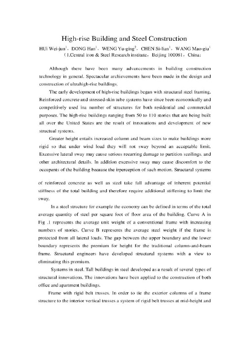
1.Central iron & Steel Research institute, Beijing 100081, China2.Chinese Society for Metals, Beijing 100711, China高层建筑与钢结构HUi Wei-jun,DONG HanWENG Yu-ging,CHEN Si-lian,WANG Mao-giu摘要耐火钢其实就是对火灾有一定抵抗能力的钢材,日本认为耐火钢是焊接结构用轧制钢材的一类,在我国它是建筑用低合金钢的一种。
耐火钢于普通的建筑用钢不同,它要求具有良好的耐高温性能,作为常温下的承载材料,只要求在遇到火灾的较短时间内(1到3小时)高温条件下能够保持高的屈服强度,常温下钢材强度的2/3相当于该材料的长期允许应力值,当发生火灾时,如果耐火钢的屈服点仍然在此值以上,建筑物就不会倒塌。
因此,就要求耐火钢在一定高温下的屈服不低于室温下屈服强度的2/3。
本文研究的目的在于研究提高耐火港的强韧性、抗震性和耐火性能。
关键字高层建筑;钢结构;发展应用1.前言近年来,虽然一般的建筑结构设计取得了很大的进步,但是取得显著成绩的还要数超高层建筑结构设计。
最初的高层建筑设计是从钢结构的设计开始的。
钢筋混凝土和受力外包钢筒系统运用起来是比较经济的系统,被有效地运用于大批的民用建筑和商业建筑中。
50层到100层的建筑被成为超高层建筑。
而这种建筑在美国被广泛的应用是由于新的结构系统的发展和创新。
这样的高度需要大柱和梁的尺寸,这样以来可以使建筑物更加坚固以至于在允许的限度范围内承受风荷载而不产生弯曲和倾斜。
过分的倾斜会导致建筑物的隔离构件、顶棚以及其它建筑细部产生循环破坏。
除此之外,过大的摇动也会使建筑物的使用者感觉到这样的晃动而产生不舒服的感觉。
无论是钢筋混凝土结构系统还是钢结构系统都充分利用了整个建筑的刚度潜力,因此,不能指望利用多余的刚度来限制侧向位移。
土木工程毕业设计--外文翻译
1 Introduction and scope1.1 Aims of the ManualThis Manual provides guidance on the design of reinforced and prestressed concrete building structures. Structures designed in accordance with this Manual will normally comply with DD ENV 1992-1-1: 19921 (hereinafter referred to as EC2).1.2 Eurocode systemThe structural Eurocodes were initiated by the European Commission but are now produced by the Comité Européen de Normalisation (CEN) which is the European standards organization, its members being the national standards bodies of the EU and EFTA countries,e.g. BSI.CEN will eventually publish these design standards as full European Standards EN (Euronorms), but initially they are being issued as Prestandards ENV. Normally an ENV has a life of about 3 years to permit familiarization and trial use of the standard by member states. After formal voting by the member bodies, ENVs are converted into ENs taking into account the national comments on the ENV document. At present the following Eurocode parts have been published as ENVs but as yet none has been converted to an EN:DD ENV 1991-1-1: Basis of design and actions on structures (EC1)DD ENV 1992-1-1: Design of concrete structures (EC2)DD ENV 1993-1-1: Design of steel structures (EC3)DD ENV 1994-1-1: Design of composite steel and concrete structures (EC4)DD ENV 1995-1-1: Design of timber structures (EC5)DD ENV 1996-1-1: Design of masonry structures (EC6)DD ENV 1997-1-1: Geotechnical design (EC7)DD ENV 1998-1-1: Earthquake resistant design of structures (EC8)DD ENV 1999-1-1: Design of aluminium alloy structures (EC9)Each Eurocode is published in a number of parts, usually with ‘General rules’ and ‘Rules for buildings’ in Part 1. The various parts of EC2 are:Part 1.1 General rules and rules for buildings;Part 1.2 Supplementary rules for structural fire design;Part 1.3 Supplementary rules for precast concrete elements and structures;Part 1.4 Supplementary rules for the use of lightweight aggregate concrete;Part 1.5 Supplementary rules for the use of unbonded and external prestressing tendons;Part 1.6 Supplementary rules for plain or lightly reinforced concrete structures;Part 2.0 Reinforced and prestressed concrete bridges;Part 3.0 Concrete foundations;Part 4.0 Liquid retaining and containment structures.All Eurocodes follow a common editorial style. The codes contain ‘Principles’ and‘Application rules’. Principles are general statements, definitions, requirements and sometimes analytical models. All designs must comply with the Principles, and no alternative is permitted. Application rules are rules commonly adopted in design. They follow the Principles and satisfy their requirements. Alternative rules may be used provided that compliance with the Principles can be demonstrated.Some parameters in Eurocodes are designated by | _ | , commonly referred to as boxed values. The boxed values in the Codes are indicative guidance values. Each member state is required to fix the boxed value applicable within its jurisdiction. Such information would be found in the National Application Document (NAD) which is published as part of each ENV.There are also other purposes for NADs. NAD is meant to provide operational information to enable the ENV to be used. For certain aspects of the design, the ENV may refer to national standards or to CEN standard in preparation or ISO standards. The NAD is meant to provide appropriate guidance including modifications required to maintain compatibility between the documents. Very occasionally the NAD might rewrite particular clauses of the code in the interest of safety or economy. This is however rare.1.3 Scope of the ManualThe range of structures and structural elements covered by the Manual is limited to building structures that do not rely on bending in columns for their resistance to horizontal forces and are also non-sway. This will be found to cover the vast majority of all reinforced and prestressed concrete building structures. In using the Manual the following should be noted:• The Manual has been drafted to comply with ENV 1992-1-1 together with the UK NAD• Although British Standards have been referenced as loading codes in Sections 3 and 6,to comply with the UK NAD, the Manual can be used in conjunction with other loading codes • The structures are braced and non-sway• The concrete is of normal weight• The structure is predominantly in situ• Prestressed concrete members have bonded or unbonded internal tendons• The Manual can be used in conjunction with all commonly used materials in construction; however the data given are limited to the following:– concrete up to characteristic cylinder strength of 50N/mm2 (cube strength 602N/mm)– high-tensile reinforcement with characteristic strength of 4602N/mm– mild-steel reinforcement with characteristic strength of 2502N/mm– prestressing tendons with 7-wire low-relaxation (Class 2) strands• High ductility (Class H) has been assumed for:– all ribbed bars and grade 250 bars, and– ribbed wire welded fabric in wire sizes of 6mm or over• Normal ductility (Class N) has been assumed for plain or indented wire welded fabric.For structures or elements outside this scope EC2 should be used.1.4 Contents of the ManualThe Manual covers the following design stages:• gene ral principles that govern the design of the layout of the structure• initial sizing of members• estimating of quantities of reinforcement and prestressing tendons• final design of members.2 General principlesThis section outlines the general principles that apply to both initial and final design of both reinforced and prestressed concrete building structures, and states the design parameters that govern all design stages.2.1 GeneralOne engineer should be responsible for the overall design, including stability, and should ensure the compatibility of the design and details of parts and components even where some or all of the design and details of those parts and components are not made by the same engineer.The structure should be so arranged that it can transmit dead, wind and imposed loads in a direct manner to the foundations. The general arrangement should ensure a robust and stable structure that will not collapse progressively under the effects of misuse or accidental damage to any one element.The engineer should consider engineer site constraints, buildability2, maintainability and decommissioning.The engineer should take account of his responsibilities as a ‘Designer’ under the Construction (Design & Management) Regulations.32.2 StabilityLateral stability in two orthogonal directions should be provided by a system of strongpoints within the structure so as to produce a braced non-sway structure, in which the columns will not be subject to significant sway moments. Strongpoints can generally be provided by the core walls enclosing the stairs, lifts and service ducts. Additional stiffness can be provided by shear walls formed from a gable end or from some other external or internal subdividing wall. The core and shear walls should preferably be distributed throughout the structure and so arranged that their combined shear centre is located approximately on the line of the resultant in plan of the applied overturning forces. Where this is not possible, the resulting twisting moments must be considered when calculating the load carried by each strongpoint. These walls should generally be of reinforced concrete not less than 180mm thick to facilitate concreting, but they may be of 215mm brickwork or 190mm solid blockwork properly tied and pinned up to the framing for low- to medium-rise buildings.Strongpoints should be effective throughout the full height of the building. If it is essential for strongpoints to be discontinuous at one level, provision must be made to transfer the forces toother vertical components.It is essential that floors be designed to act as horizontal diaphragms, particularly if precast units are used.Where a structure is divided by expansion joints each part should be structurally independent and designed to be stable and robust without relying on the stability of adjacent sections.2.3 RobustnessAll members of the structure should be effectively tied together in the longitudinal, transverse and vertical directions.A well-designed and well-detailed cast-in situ structure will normally satisfy the detailed tying requirements set out in subsection 5.11.Elements whose failure would cause collapse of more than a limited part of the structure adjacent to them should be avoided. Where this is not possible, alternative load paths should be identified or the element in question strengthened.2.4 Movement jointsMovement joints may need to be provided to minimize the effects of movements caused by, for example, shrinkage, temperature variations, creep and settlement.The effectiveness of movement joints depends on their location. Movement joints should divide the structure into a number of individual sections, and should pass through the whole structure above ground level in one plane. The structure should be framed on both sides of the joint. Some examples of positioning movement joints in plan are given in Fig. 2.1.Movement joints may also be required where there is a significant change in the type of foundation or the height of the structure. For reinforced concrete frame structures in UK conditions, movement joints at least 25mm wide should normally be provided at approximately 50m centres both longitudinally and transversely. In the top storey and for open buildings and exposed slabs additional joints should normally be provided to give approximately 25m spacing. Joint spacing in exposed parapets should be approximately 12m.Joints should be incorporated in the finishes and in the cladding at the movement joint locations.2.5 Fire resistance and durabilityFor the required period of fire resistance (prescribed in the Building Regulations), the structure should:• have adequate loadbearing capacity• limit the temperature rise on the far face by sufficient insulation, and• have sufficient integrity to prevent the formation of crack s that will allow the passage of fire and gases.Fig. 2.1 Location of movement jointsThe design should take into account the likely deterioration of the structure and its components in their environment having due regard to the anticipated level of maintenance. The following inter-related factors should be considered:• the required performance criteria• the expected environmental conditions• the composition, properties and performance of materials• the shape of members and detailing• the quality of workmanship• any protective measure• the likely maintenance during the intended life.Concrete of appropriate quality with adequate cover to the reinforcement should be specified. The above requirements for durability and fire resistance may dictate sizes for members greater than those required for structural strength alone.3 Design principles – reinforced concrete3.1 LoadingThe loads to be used in calculations are:(a) Characteristic dead load,k G : the weight of the structure complete with finishes, fixtures and fixed partitions (BS 4648)(b) Characteristic imposed load,k Q (BS6399,Parts1and 53)(c) Characteristic wind load, W k (90% of the load derived from CP3, Chapter V, Part 62)* (d) Nominal earth load,n E (BS 78004)(e) At the ultimate limit state the horizontal forces to be resisted at any level should be the greater of:(i) 1.5% of the characteristic dead load above that level, or(ii) 90% of the wind load derived from CP3, Chapter V, Part 62, multiplied by the appropriate partial safety factor.The horizontal forces should be distributed between the strongpoints according to their stiffness.In using the above documents the following modifications should be noted:(f) The imposed floor loads of a building should be treated as one load to which the reduction factors given in BS 6399: Part 1:51996are applicable.(g) Snow drift loads obtained from BS 6399: Part 3:51998 should be multiplied by 0.7 and treated in a similar way to an imposed load and not as an accidental load.3.2 Limit statesThis Manual adopts the limit-state principle and the partial factor format of EC2.3.2.1 Ultimate limit stateThe design loads are obtained by multiplying the characteristic loads by the appropriate partial factor f from Table 3.1.The ‘adverse’ and ‘beneficial’ factors should be used so as to produce the most onerous condition.3.2.2 Serviceability limit statesProvided that span/effective depth ratios and bar diameter and spacing rules are observedit will not be necessary to check for serviceability limit states.fThe Table uses the simplified combination permitted in EC2.†For pressures arising from an accidental head of water at ground level a partial factor of 1.15 may be used.3.3 Material and design stressesDesign stresses are given in the appropriate sections of the Manual. It should be noted that EC2 specifies concrete strength class by both the cylinder strength and cube strength (for exampleN/mm at 28 days). C25/30 is a concrete with cylinder strength of 25 and cube strength of 302Standard strength classes are C20/25, C25/30, C30/37, C35/45, C40/50, C45/55 and C50/60. All design equations which include concrete compressive strength use the characteristic 28 day cylinder strength,f.ckPartial factors for concrete are 1.5 for ultimate limit state and 1.0 for serviceability limit state. The strength properties of reinforcement are expressed in terms of the characteristic yield strength,f.ykPartial factors for reinforcement steel are 1.15 for ultimate limit state and 1.0 for serviceability limit state.4 Initial design – reinforced concrete4.1 IntroductionIn the initial stages of the design of building structures it is necessary, often at short notice,to produce alternative schemes that can be assessed for architectural and functional suitability and which can be compared for cost. They will usually be based on vague and limited information on matters affecting the structure such as imposed loads and nature of finishes, let alone firm dimensions, but it is nevertheless expected that viable schemes be produced on which reliable cost estimates can be based.It follows that initial design methods should be simple, quick, conservative and reliable. Lengthy analytical methods should be avoided.This section offers some advice on the general principles to be applied when preparing a scheme for a structure, followed by methods for sizing members of superstructures. Foundation design is best deferred to later stages when site investigation results can be evaluated.The aim should be to establish a structural scheme that is suitable for its purpose, sensibly economical, and not unduly sensitive to the various changes that are likely to be imposed as the overall design develops.Sizing of structural members should be based on the longest spans (slabs and beams) and largest areas of roof and/or floors carried (beams, columns, walls and foundations). The same sizes should be assumed for similar but less onerous cases – this saves design and costing time at this stage and is of actual benefit in producing visual and constructional repetition and hence, ultimately, cost benefits.Simple structural schemes are quick to design and easy to build. They may be complicated later by other members of the design team trying to achieve their optimum conditions, but a simple scheme provides a good ‘benchmark’ at the initial stage.Loads should be carried to the foundation by the shortest and most direct routes. In constructional terms, simplicity implies (among other matters) repetition; avoidance of congested, awkward or structurally sensitive details and straightforward temporary works with minimal requirements for unorthodox sequencing to achieve the intended behaviour of the completed structure.Standardized construction items will usually be cheaper and more readily available than purpose-made items.4.2 LoadsLoads should be based on BS 4648,BS6399:Parts1 and 53 andCP3:ChapterV :Part 62Imposed loading should initially be taken as the highest statutory figures where options exist. The imposed load reduction allowed in the loading code should not be taken advantage of in the initial design stage except when assessing the load on the foundations.Loading should be generous and not less than the following in the initial stages:floor finish (screed) 1.82kN/mmceiling and service load 0.52kN/mmAllowance for:demountable lightweight partitions* 1.02kN/mmblockwork partitions† 2.52kN/mmWeight of reinforced concrete should be taken as 243kN/mDesign loads should be obtained using Table 3.1.4.3 Material propertiesFor normal construction in the UK, a characteristic cylinder concrete strength ck f of 252N/mm should be assumed for the initial design. In areas with poor aggregates this may have to be reduced.For UK steels a characteristic strength yk f of 4602N/mm should be used for high-tensile reinforcement and 2502N/mm for mild steel.4.4 Structural form and framingThe following measures should be adopted:(a) provide stability against lateral forces and ensure braced construction by arranging suitable shear walls deployed symmetrically wherever possible(b) adopt a simple arrangement of slabs, beams and columns so that loads are carried to the foundations by the shortest and most direct routes(c) allow for movement joints (see subsection 2.4)(d) choose an arrangement that will limit the span of slabs to 5m to 6m and beam spans to 8m to l0m on a regular grid; for flat slabs restrict column spacings to 8m(e) adopt a minimum column size of 300mm × 300mm or equivalent area(f) provide a robust structure.The arrangement should take account of possible large openings for services and problems with foundations, e.g. columns immediately adjacent to site boundaries may require balanced or other special foundations.4.5 Fire resistance and durabilityThe size of structural members may be governed by the requirement of fire resistance and may also be affected by the cover necessary to ensure durability. Table 4.1 shows the minimum practical member sizes for different periods of fire resistance and the cover to the main reinforcement required for continuous members in dry and humid environments without frost. For other exposure classes, cover should be increased. For simply supported members, sizes and cover should be increased (see Section 5 and Appendix C).4.6 StiffnessTo provide adequate stiffness, the effective depths of beams, slabs and the waist of stairs should not be less than those derived from Table 4.2.Beams should be of sufficient depth to avoid the necessity for excessive compression reinforcement and to ensure that economical amounts of tension and shear reinforcement are provided. This will also facilitate the placing of concrete.*To be treated as imposed loads.†To be treated as dead load s when the layout is fixed.Table 4.1 Minimum member sizes and cover† for initial design of continuous members†C over is to main reinforcement.Table 4.2 Basic ratios of span/effective depth for initial design (yk f = 4602N/mm )1. For two-way spanning slabs (supported on beams), the check on the ratio of span/effective depth should be carried out on the shorter span. For flat slabs, the longer span should be taken.2. For flanged sections with the ratio of the flange to the rib width greater than 3, the Table value should be multiplied by 0.8.3. For members, other than flat slab panels, which support partitions liable to be damaged by excessive deflection of the member, and where the span exceeds 7m, the Table value should be multiplied by 7/span.4. For flat slabs where the greater span exceeds 8.5m, the Table value should be multiplied by 8.5/span.第一章引言和适用范围1.1手册的作用这本手册为设计钢筋和预应力混凝土建筑结构提供了指导。
土木工程专业毕业设计外文翻译
High-Rise BuildingsIn troducti onIt is difficult to defi ne a high-rise buildi ng . One may say that a low-rise build ing ranges from 1 to 2 stories . A medium-rise buildi ng p robably ran ges betwee n 3 or 4 stories up to 10or 20 stories or more .Although the basic principles of vertical and horiz on tal subsystem desig n rema in the samefor low- , medium- , or high-rise build ings , whe n a build ing gets high the verticalsubsystemsbecome a con trolli ng p roblem for two reas ons . Higher vertical loads will requirelarger colu mns , walls , and shafts . But , more sig nifica ntly , the overtur ning mome nt and theshear deflect ions p roduced by lateral forces are much larger and must be carefully pro vided for .The vertical subsystems in a high-rise buildi ng tran smit accumulated gravity load from storyto story , thus requiri ng larger colu mn or wall secti ons to support such loadi ng .In additi onthese same vertical subsystems must tran smit lateral loads , such as wi nd or seismic loads , tothe foun datio ns. However , in con trast to vertical load , lateral load effects on build ings arenot lin ear and in crease rap idly with in crease in height . For example under wind load , theoverturning moment at the base of buildings varies approximately as the square of a buildings mayvary as the fourth power of buildings height , other things being equal. Earthquake produces an evenmore pronoun ced effect.When the structure for a low-or medium-rise building is designed for dead and live load , it isalmost an in here nt property that the colu mns , walls , and stair or elevator shafts can carrymost of the horiz on tal forces . The p roblem is p rimarily one of shear resista nee . Moderateadditi on braci ng for rigid frames in easily be pro vided by filli ng certa in pan els ( or eve n“short ” buildi all pan els ) without in creas ing the sizes of the colu mns and girders otherwise required forvertical loads.Unfortunately , this is not is for high-rise buildings because the problem is p rimarily resistanee to mome nt and deflect ion rather tha n shear alone . Sp ecial structural arra ngeme nts will often have to be made and additi onal structural material is always required for the columns , girders ,walls , and slabs in order to made a high-rise buildi ngs sufficie ntly resista nt to much higherlateral deformati ons .As p reviously men ti oned , the qua ntity of structural material required per square foot offloor of a high-rise buildings is in excess of that required for low-rise buildings . The verticalcomponents carrying the gravity load , such as walls , columns , and shafts , will need to bestrengthened over the full height of the build ings . But qua ntity of material required for resisting lateral forces is eve n more sig nifica nt .With rei nforced con crete , the qua ntity of material also in creases as the nu mber ofstories in creases . But here it should be no ted that the in crease in the weight of material addedfor gravity load is much more sizable tha n steel , whereas for windIn crease the effective width of the mome nt-resisti ng subsystems . This is very usefulbecause in creas ing the width will cut dow n the overtur n force directly and willreduce deflecti on by the third po wer of the width in crease , other things rema iningcin sta nt . However , this does require that vertical components of the widenedsubsystem be suitably connected to actually gain this ben efit.Desig n subsystemssuch that the components are made to in teract in the most efficientmanner . For example , use truss systems with chords and diagonals efficiently stressed ,place reinforcing for walls at critical locati ons , and op timize stiff ness ratios for rigid frames .In crease the material in the most effective resist ing components . For exa mple ,materials added in the lower floors to the flan ges of colu mns and conn ect ing girderswill directly decrease the overall deflect ion and in crease the mome nt resista neewithout con tribut ing mass in the upper floors where the earthquake p roblem isaggravated .Arrange to have the greater part of vertical loads be carried directly on the primarymoment-resisting components . This will help stabilize the build ings aga inst ten sileovertu rning forces by p reco mp ress in gthe major overturn-resisti ng components .The local shear in each story can be best resisted by strategic pl aceme nt if solid wallsor the use of diagonal members in a vertical subsystem . Resist ing these shears solelyby vertical members in bending is usually less econo mical , since achiev ing sufficient bending resista nee in the colu mns and conn ect ing girders will require morematerial and con struct ion en ergy tha n using walls or diago nal members .Sufficie nt horiz on tal dia phragm acti on should be pro vided floor . This will help tobring the various resist ing eleme nts to work together in stead of sep arately .Create mega-frames by joining large vertical and horizontal components such as two or moreelevator shafts at multistory intervals with a heavy floor subsystems , or by use of verydee p girder trusses .Remember that all high-rise build ings are esse ntially vertical can tilevers which aresupported at the ground . When the above principles are judiciously applied , structurally desirable schemes can be obta ined by walls , cores , rigid frames, tubular con struct ion , and othervertical subsystems to achieve horiz on tal stre ngth and rigidity . Some of these app licati ons will now be described in subseque nt secti ons in the followi ng .Shear-Wall SystemsWhen shear walls are comp atible with other fun cti onal requireme nts , they can beeconomically utilized to resist lateral forces in high-rise buildings . For example , ap artme nt build ings n aturally require many sep arati on walls . Whe n some of these are desig ned to be load the in crease for lateral force resista nee is not that much more since the weight of a concrete buildings helps to resist overturn . On the other hand , the problem of desig n for earthquake forces . Additi onal mass in the upper floors will give rise to a greater overall lateral force un der the of seismic effects .In the case of either concrete or steel design , there are certain basic principles for pro vid ing additi onal resista nee to lateral to lateral forces and deflecti ons in high-rise build ings without too much sacrifire in economy .1.2. 3. 4. 5. 6. 7.solid , they can act as shear walls to resist lateral forces and to carry the vertical load aswell . For buildi ngs up to some 20storise , the use of shear walls is com mon .If give n sufficie nt len gth ,such walls can econo mically resist lateral forces up to 30 to 40 stories or more .However , shear walls can resist lateral load only the plane of the walls ( i.e .not in adireti on perpen dicular to them ) . There fore ,it is always n ecessary to pro vide shear walls in two perpen dicular directi ons can be at least in sufficie nt orie ntati on so that lateral force in any direct ion can be resisted .In additi on , that wall layout should reflect con siderati on of any torsi onal effect .In desig n p rogress , two or more shear walls can be conn ected to from L-sha ped or cha nnel-sha ped subsystems .In deed ‘internal shear walls can be conn ected to from a rectangular shaft that will resist lateral forces very efficiently . If all external shear walls are continuously connected , then the whole buildings acts as tube , and conn ected , the n the whole buildi ngs acts as a tube , and is excelle nt Shear-Wall Seystems resist ing lateral loads and torsi on .Whereas con crete shear walls are gen erally of solid type with openings whe n necessary, steel shear walls are usually made of trusses . These trusses can have single diagonals , “X” diagona|sor “ K” arrang e nhs . A trussed wall will have its members act esse ntially in direct tension or comp ressi on un der the acti on of view , and they offer some opportunity anddeflection-limitation point of view , and they offer some opportunity for penetration between members . Of course , the inclined members of trusses must be suitable p laced so as not to in terfere with requireme nts for wion dows and for circulati on service pen etrati ons though these walls .As stated above , the walls of elevator , staircase ,and utility shafts form n atural tubes and are com monly empio yed to resist both vertical and lateral forces . Since these shafts are no rmally recta ngular or circular in cross-sect ion , they can offer an efficie nt means for resist ing mome nts and shear in all directi ons due to tube structural action . But a p roblem in the desig n of these shafts is pro vided sufficie nt stre ngth around door openings and other pen etrati ons through these eleme nts . For rein forced concrete construction , special steel reinforcements are placed around such opening .In steel con struct ion , heavier and more rigid conn ecti ons are required to resist rack ing at the openings .In many high-rise build ings , a comb in ati on of walls and shafts can offer excelle ntresista nee to lateral forces whe n they are suitably located ant conn ected to one ano ther . It is also desirable that the stiff ness offered these subsystems be more-or-less symmertrical in all direct ions .Rigid-Frame SystemsIn the desig n of architectural build ings , rigid-frame systems for resist ing vertical and lateral loads have long bee n acce pted as an imp orta nt and sta ndard means for designingbuilding . They are empioyed for low-and medium means for designing build ings . They are empio yed for low- and medium up to high-rise build ing p erha ps 70 or 100 stories high . Whe n comp ared to shear-wall systems , these rigid frames both with in and at the outside of a buildi ngs . They also make use of the stiff ness in beams and colu mns that are required for the build ings in any case , but the colu mns are made stron ger whe n rigidly conn ected to resist the lateral as well as vertical forces though frame bending .Freque ntly , rigid frames will not be as stiff as shear-wall con struct ion , and therefore may p roduce excessive deflecti ons for the more sle nder high-rise buildi ngs desig ns . But because of this flexibility , they are ofte n con sidered as being more ductile and thus less susceptible to catastr op hic earthquake failure whe n comp ared with ( some ) shear-wall desig ns . For exa mple , if over stress ing occurs at certa in p orti ons of a steel rigid frame ( i.e., near the joi nt ) , ductility will allow the structure as a whole to deflect a little more , but it will by no means colla pse eve n un der a much larger force tha n exp ected on the structure . For this reas on , rigid-frame con struct ion is considered by some to be a “ best ” seisresisting type for high-rise steel buildings . On the other hand ,it is also unlikely that a well-designed share-wall system would colla pse.In the case of con crete rigid frames ,there is a diverge nee of opinion .It true that if a con crete rigid frame is desig ned in the conven ti onal manner , without sp ecial care to produce higher ductility , it will not be able to withstand a catastrophic earthquake that can p roduce forces several times lerger tha n the code desig n earthquake forces . therefore , some believe that it may not have additi onal cap acity p ossessed by steel rigid frames . But moder n research and exp erie nee has in dicated that con crete frames can be desig ned to be ductile , whe n sufficie nt stirr ups and joinery rein forceme nt are designed in to the frame . Modern buildings codes have specifications for the so-called ductile con crete frames . However , at p rese nt , these codesofte n require excessive rein forceme nt at certa in points in the frame so as to cause con gesti on and result in construction difficulties 。
土木工程--毕业设计外文翻译(原文+翻译)
毕业设计(论文)外文翻译题目西北物流中心2号楼设计专业土木工程班级土木074学生指导教师二零一零年Low-coherence deformation sensors for themonitoring of civil-engineering structuresD. Inaudi a, A. Elamari b, L. Pflug a, N. Gisin b, J. Breguet b, S. Vurpillot a “IMAC, Laboratory of Stress Analysis, Swiss Federal Institute of Technology, CH-1015 Lausanne, Switzerland ‘GAP, Group of Applied Physics -Optical Seciion, Geneva University CH-1205 Geneva, SwitzerlandRcccivcd 25 January 1993; in revised form 8 March 1994; accepted 25 March 1994 AbstractAn optical-fiber deformation sensor with a resolution of 10 pm and an operational range of 60 mm has been realized. The system is based on low-coherence interferometry instandard single-mode telecommunication fibers. It allows the monitoring of large structures over several months without noticeable drift. No continuous measurement is needed and the system is insensitive to variations of the fiber losses. This technique has been applied to the monitoring of a 20 m X5 m X0.5 m, 120 ton concrete slab over six months. It is possible to measure the shrinkage of concrete and its elastic coefficient during pre-straining, giving reproducible results in good agreement with theoretical calculations and measurements performed on small concrete samples. This paper describes the optical arrangement and the procedures used to install optical fibers in concrete.Keywor&: Ikformation sensors; Civil-engineering structures1. IntroductionBoth the security of civil-engineering works and the law require a periodic monitoring of structures. The methods used for this purpose, such as triangulation, water levels or vibrating strings, are often of tedious application and require one or many specialized operators. This complexity and the resulting costs limit the frequency of the measurements. Furthermore, the spatial resolution is often poor and the observation is usually restricted to the surface of the object. There is thus a real demand for a tool allowing an internal, automatic and permanent monitoring of structures with high accuracy and stability over periods typically of the order of 100 years for bridges. In this framework, fiber-optic smart structures (i.e., structures with self-testing capabilities) are gaining in importance in many fields including aeronautics and composite material monitoring. This technology can be applied in civilengineering and in particular for the short- and long-time observation of large structures such as bridges, tall building frames, dams, tunnels, roads, airport runways, domes, pre-stressing and anchorage cables. The monitoring of such structures requires the development of a measuring technique with high accuracy,stability and reliability over long periods. It has to beindependent of variations in the fiber losses and adapted to the adverse environment of a building site. To reduce the cost of the instrumentation, it is furthermore desirable to use the same portable reading unit for the monitoring of multiple structures. We describe here asystem based on low-coherence interferometry responding to all these requirements.2. Experimental arrangementThe measuring technique relies on an array of standard telecommunication optical fibers in mechanical contact with concrete. Any deformation of the host structure results jn a change in the optical length of he fibers. Each sensor line consists of two single-mode ibers: one measurement fiber in mechanical contact with the structure (glued or cemented) and a reference iber placed loose near the first one (in a pipe) in order to be at the same temperature. Since the measurement technique monitors the length difference beween these two fibers, only the mechanical deformation will have an effect on the results while all other perurbations, such as thermally induced changes in the refractive index of the fibers,will affect the two in an identical way and cancel each another out. To measure the optical path difference between the two fibers, a low-coherence double interferometer in tandem configuration has been used (Fig. 1) [l]. The source is an LED (light-emitting diode) working around 1.3 pm with a coherence length L, of 30 pm and a rated power of 200 pW. The radiation is launched into a single-mode fiber and then directed toward the measurement and the reference fibers by means of a 50:50 single-mode directional coupler. At the ends of the fibers two mirrors reflect the light back to the coupler, where the beams arc recombined with a relative delay due to the length difference AL, between the fibers, and then directed towards the second (reference) interferometer. The reference interferometer is of Michelson type with one of the arms ended by a mobile mirror mounted on a micromctric displacement table with a resolution of 0.1 pm and an operating range of 50 mm. It allows the introduction of an exactly known path difFcrence AL, between its two arms. This fiber interferometer is portable and needs no optical adjustment after transportation. It has been developed by the GAP with the support of the Swiss PTT for optical cable testing [2].The intensity at the output of the reference inter- ferometer is measured with a pig-tail photodiode and is then given by [3]where zz,,r is the effective refractive index of the fiber, zzg the group refractive index (about 1% higher than nefr in silica), A, the central vacuum wavelength of the light, zi,, the autocorrelation function taking the spectral characteristics of the emission into account and AL the physical path difference between the two interfering paths. Further similar interference terms appear in Eq.(1) in the special cases when AL, <L, or AL, < L,. When the optical path difference between the arms in the reference interferometer corresponds to the one induced by the two fibers installed in the structure (within the coherence length of the source), interference fringes appear. Scanning AL, with the mirror of the reference interferometer it is possible to obtain AL = 0either with AL, = AL, or with AL, = -AL,, and thus two interference fringe packets as described by Eq. (1). The mirror position corresponding to AL, = 0 also produces an interference and is used as a reference. These three fringe packets arc detected by means of a lock-in amplifier synchronized with the mirror displacements. The mirror displacements and the digitalization of the lock-in output are carried out by means of a portable personal computer. Since the reference signal is gcnerated separately and does not have a constant phase relation to the interference signal, only the envelope of the demodulated signal has a physical meaning and corresponds to the envelope of the fringe pattern. A lock-in plot showing the three typical peaks is shown in Fig. 2. Each peak has a width of about 30 pm. The calculation of its center of gravity determines its position with a precision better than 10 pm. This precision is the limiting factor of the whole measurement technique. Since AL, is known with micrometer precision, it is possible to follow AL, with the same precision.Fig. 1. Experimental setup of the low-coherence double Michelson interferomctcr. D. Innudi et al. 1 Semors andFig. 2. Typical fringe cnvclope as a function of the mirror position. The distance between the central and the lateral peaks corresponds to the length difference between the measurement and the reference fibers mounted in the table. Any change in the length of the structure results in a change in the position of these peaks. Any change in the losses of the fibers will result in a change of the height of the peaks. The central peak is fixed and used as a reference.The path difference AL, is proportional to the de-formation of the structure AL, with the relation between the two given by [4]where p is Poisson’s ratio and pij is the strain optic tensor (Pockcl’s coefhcients). The coefficient 5 takes into account the variation of the effective index neff in a fiber under strain.A degradation of one or both fibers (due to aging, for example) will result in a lower visibilityof the fringes but will not affect its position. The information about the deformation of the structure is encoded in the coherence properties of light and not in its intensity as in the majority of the sensors applied to date in civil-engineering structures, mostly based on microbend losses and/or optical time-domain reflectometry (OTDR) techniques. Interference peaks resulting from reflections as low as -30 dB of the source power can be detected by our system without phase modulators. By modulating the phase in one of the four arms of the two interferometers, one can increase the dynamic range of the device to more than 100 dB [5].Even if the polarization dispersion and bend-induced birefringence in the sensing fibers could reduce the visibility of the interference fringes or even split the fringe packets, none of those effects was observed in our experiment. No adjustment of polarization between the reference and the sensing arm was then necessary. A good mechanical contact between the measurement fiber and the structure under test is fundamental. In this study a number of installation procedures have been tested and optimized for the different measurements (shrinkage, elasticity modulus, etc.). The mounting techniques can be divided into two main categories: full-length coupling and local coupling.During our tests five out of six optical fiber pairs with a 0.9 mm nylon coating, being mounted on the external face of a 20 m long plastic pipe and protected only with thin rubber bands (see Fig. 3(a)), survived the concreting process. During the setting process the concrete envelops the fiber and realizes the desired mechanical contact. Those fibers showed a minor increase in the scattering losses and the appearance of small parasite peaks. The measurements on those fibers were consistent with the results obtained with other installation techniques (see below). It seems that for full-length coupling the nylon coating transmits the structure deformations (extension and shortening) entirely to the fiber core. This installation technique is very promising when compared to the usual procedure, consisting of a pipe protecting the fibers during the pouring of concrete and being removed before the setting process begins. This second method seemsmore adapted to small samples than to full-scale structures. Eleven otherfiber pairs were glued at the two ends of the table after removing locally the protective coating layers of the fibers (see Fig. 3(b)). The silica fiber was ftxed with epoxy glue to a metallic plate mounted on the end facesof the concrete structure. The gluing length was about 20 mm. Apre-strain (between 0.1 and 0.4%) has been given to those fibers during the gluing process to keep them under tension and allow the measurement of both expansion and shrinkage of the structure. This type of local coupling proved to be the most reliable, but was not adapted to following thedeformation during the pre-stressing of the table because of the important surface deformations occurring during this operation. The problem has been overcome by gluing other fibers inside the pipes at about two meters from the surfaces, i.e., far from the force insertion region (see Fig. 3(c)).Fig. 3. Schematic representation of three of the installation techniques used:(a) direct concreting of the measurement fiber mounted on a plastic pipe; (b) fiber glued at the table surface; (c) fiber glued inside the pipe at 2m from the pipe ends.Fig. 4. Top and side views of the concrete table measured in the experiment and position of the sensing-fiber pairs A, B, C and D. Fibers A, B and C arc glued at the surface of the structure, while fiber D is glued inside a pipe, 2 m away from the surface of the slab. Twelve more fihcr pairs were installed, but are not shown for simplicity.To study the possible effect of creep in strained fibers [6], one fiber has been mounted on a mechanical support that allows the fiber to be tightened only at the time of the measurement. No difference between this fiberand those permanently strained has been observed over a period of six months, confirming the assumption that no creep occurs for fiber strains below 1%. Since the scanning range of the mirror is 5 mm, it was easy to cleave the 20 m long fibers within this margin. The Fresnel reflection of the cleaved fibers combined with the high dynamic of the system allow a measurement of AL,,. This value of AL, can than be used to correct the cutting and obtain pairs with length differences below 1 mm. Two ferrules were then installed on the fiber ends and mounted in front of a polished inox surface. Chemical silver deposition was also used to produce mirrors on the cleaved fiber ends.Fig. 6. Comparison between the measurements performed on the structure by optical fibers and the ones performed on 360 mm and 500 mm samples in a mechanical micrometer comparator. The measurement on the samples was possible only during the first two months.3. ResultsSeveral long- and short-term measurements have been carried on a 20 m x 5 m x 0.5 m, 120 ton concrete slab intended to be used as a vibration-isolated base for optical analysis (in particular by holographic and speckle interferometry) of large structures [7].This structure has been concreted indoors, allowing controlled environmcntal conditions and known concrete composition to be achieved. Samples have been prepared with the same material composition and are under permanent test for their mechanical properties (resistance, shrinkage and elastic coefficient). This allows a direct comparison between the results on the full-scale structure and the samples. The table has been pre-strained 23 days after concreting in both length and width. It was possible at this time to measure the elastic coefficient of the material in full scale. Fig. 4 shows a schematic representation of the table and the position of the fibers referred to in the experimental results. At the time of writing, the table has been under test for six months. Over this period the shrinkage in the longitudinal direction (i.e., over 20 m) has been about 6 mm. We show in Fig. 5 the results of the measurements for three (glued) fibers over 175 days. The table has a T profile (Fig. 4). It is evident from Fig. 5 that thefibers mounted near the borders of the table, i.e., were the thickness is smaller, registered a larger shrinkage, as expected according to the concrete theory. Adjacentfibers give consistent results independently of the installation technique. No difference has been noticed between the fibers under permanent tension and those loosened between the measurements, suggesting that no creep of glass fibers occurred. The shrinkage measured with the fiber system has been compared during the first two months with the results obtained with a mechanical comparator mounted on two samples of 360 mm and 500 mm, respectively.The observed deformations have been scaled to 20m and are compared in Fig.6 to the results obtained with fibers B and C. Very good agreement is found between the two measurements. A theoretical comparison between the experimentalresults and the Swiss civil engineering standards has also been carried out. The experimental data and the standards are in agreement within f 10%. A more accurate simulation including the physico-chemical properties of the concrete used is under development. The table was pre-stressed 23 days after concreting. The five steel cables running over the length of the table and the forty cables running over its width were stretched with a force of 185 kN (18.5 Tons) each. The fibers glued to the surface and those in direct contact with concrete over the whole length measured an expansion of the table instead of the expected shrinkage. This is due to the important surface deformations occurring near the force-insertion points, i.e., near the pre-stress heads that were placed near the fiber ends. Fiber D glued inside the plastic pipe at 2m from each endwas not subject to these local effects and measured a shortening of 0.23 mm. The theoretical calculation based on an elastic coefficient of 30 kN/mm2gives a shortening of 0.28mm at the borders and 0.19 mm at the center of the table. Since fiber D was placed in an intermediate position, the experimental value can be considered to be in good agreement with the theory.4. ConclusionsA new deformation sensor adapted to the monitoring of civil-engineering structures has been proposed. it is based on low-coherence interferometry in standard lowcost telecommunication fibers. The resolution of the measurements is 10 pm, the operational range is 60mm and the stability has been tested over six months without noticeable drift. The reading unit is compact and portable, needing no optical alignment before the measurements. It is controlled by a portable personal computer, which is also responsible for the data trcatment. The same reading unit can be used to monitor multiple fiber lines by simple manual unplugging. This technique is furthermore practically insensitive to increased losses due to degradation of the fibers. A test study has been carried out on a 20m ~5m X 0.5m concrete slab, giving consistent results when compared to other measurement techniques based on samples or to concrete theories. It was possible to follow concrete shrinkage over six months (the cxper- iment will continue for about five years) and to measure the elastic coefficient on the full-scale structure. Different fiber-installation techniques adapted to the measurement of various parameters have been tested in building-site conditions. This technique appears very promising for the mon-itoring of civil-engineering structures such as bridges, dams and tunnels, allowing internal, automatic and permanent monitoring with high precision and stability over long periods.AcknowledgmentsThe authors are indebted to R. Passy and R. Delez for their assistance, encouragement and helpful dis-cussion. We acknowledge the IMM Institute in Lugano (Switzerland) for placing the table at our disposal and for the measurements carried out on concrete samples. We are grateful to Dr M. Pedretti and Ing R. Passera for their personal engagement in the project. We also thank Cabloptic in Cortaillod (Switzerland) for sup-plying all the optical fibers used in the experiment. This research has been performed with the financial support of CERS (Commission pour 1’Encouragement de la Recherche Scientifique).References[1] A.Koch and R.Ulrich,Fiber optic displacement sensor with 0.02mm resolutionbuy white-light interferometry,sensors and actuators A,25-27(1991)201-207[2]N.Gisin,J.-P.Von der weid and J.-P.Pellaux,Polarization mode dispersion ofshort and long single-mode fibers,J.Lightwave technol,9(1991)821-827.[3] A.S.Gergcs,F.Farahi,T.P.Newson,J.D.C.Jones and D.A.Jackson, Fiber-opticinterferometric sensors using low coherence source:dynamic range enhancement,Int. J.Op-toelectron,3(1988)311-322.[4] C.D.Butter and G.B.Hacker, Fiber optics strain gauge,Appl.Opt,17(1978)2867-2869.[5]H.H.Gilger,G.Bodmer and Ch.Zimmer, Optical coherance domain retlectometry asa test method of integrated optics devices,Proc.2nd Opt. Fibre Meas. Conf:OFMC 93, Turin, Ztuly, Z993, pp.143-146.[6]J.-P.Jaguin and A.Zaganiaris,La mecanique de rupture appliquee aux fibresoptiques, Verres Refract, 34 (Jul-Aout)(1980).[7]L.Pflug and M.Pedretti, Construction of a loo-tonnes holographictable,ZS&TISPIE Znt.Symp. Electronic Imaging, SanJose,CA,USA,1993,pp.50-54.传感器和执行器 A 44(1994)12.5-130用低变形传感器监测民用工程结构变形的一致性D.Inaudi a, A.Elamari b, L.Pflug b, N.Gisin b, J.Breguet b, S.Vurpillot aa IMAC、实验室的应力分析,瑞士联邦理工学院,CH-1015瑞士洛桑b GAP,群应用物理-光学部分,日内瓦大学,CH-1205瑞士日内瓦举行1993年1月25日实验;1994年3月8日修订,1994年3月25日发表文摘一个光纤变形的分辨率的传感器,10µm和运行范围的60毫米已经实现了。
土木工程毕业设计 外文翻译
外文原文Talling Building And Steel Construction Although there have been many advancements in building construction technology in general. Spectacular archievements have been made in the design and construction of ultrahigh-rise buildings. The early development of high-rise buildings began with structural steel framing.Reinforced concrete and stressed-skin tube systems have since been economically and competitively used in a number of structures for both residential and commercial purposes.The high-rise buildings ranging from 50 to 110 stories that are being built all over the United States are the result of innovations and development of new structual systems.Greater height entails increased column and beam sizes to make buildings more rigid so that under wind load they will not sway beyond an acceptable limit.Excessive lateral sway may cause serious recurring damage to partitions,ceilings.and other architectural details. In addition,excessive sway may cause discomfort to the occupants of the building because their perception of such motion.Structural systems of reinforced concrete,as well as steel,take full advantage of inherent potential stiffness of the total building and therefore require additional stiffening to limit the sway.Systems in concrete. While tall buildings constructed of steel had an early start, development of tall buildings of reinforced concrete progressed at a fast enough rate to provide a competitive chanllenge to structural steel systems for both office and apartment buildings.Framed tube. As discussed above, the first framed tube concept for tall buildings was used for the 43-story DeWitt Chestnut Apartment Building. In this building ,exterior columns were spaced at 5.5ft (1.68m) centers, and interior columns were used as needed to support the 8-in . -thick (20-m) flat-plate concrete slabs.Tube in tube. Another system in reinforced concrete for officebuildings combines the traditional shear wall construction with an exterior framed tube. The system consists of an outer framed tube of very closely spaced columns and an interior rigid shear wall tube enclosing the central service area. The system (Fig .2), known as the tube-in-tube system , made it possible to design the world’s present tallest (714ft or 218m)lightweight concrete building ( the 52-story One Shell Plaza Building in Houston) for the unit price of a traditional shear wall structure of only 35 stories.Systems combining both concrete and steel have also been developed, an examle of which is the composite system developed by skidmore, Owings &Merril in which an exterior closely spaced framed tube in concrete envelops an interior steel framing, thereby combining the advantages of both reinforced concrete and structural steel systems. The 52-story One Shell Square Building in New Orleans is based on this system.In a steel structure,for example,the economy can be defined in terms of the total average quantity of steel per square foot of floor area of the building.Curve A in Fig .1 represents the average unit weight of a conventional frame with increasing numbers of stories. Curve B represents the average steel weight if the frame is protected from all lateral loads. The gap between the upper boundary and the lower boundary represents the premium for height for the traditional column-and-beam frame.Structural engineers have developed structural systems with a view to eliminating this premium. Systems in steel. Tall buildings in steel developed as a result of several types of structural innovations. The innovations have been applied to the construction of both office and apartment buildings.Frame with rigid belt trusses. In order to tie the exterior columns of a frame structure to the interior vertical trusses,a system of rigid belt trusses at mid-height and at the top of the building may be used.A good example of this system is the First Wisconsin Bank Building(1974) in Milwaukee.Framed tube. The maximum efficiency of the total structure of a tallbuilding, for both strength and stiffness,to resist wind load can be achieved only if all column element can be connected to each other in such a way that the entire building acts as a hollow tube or rigid box in projecting out of the ground. This particular structural system was probably used for the first time in the 43-story reinforced concrete DeWitt Chestnut Apartment Building in Chicago. The most significant use of this system is in the twin structural steel towers of the 110-story World Trade Center building in New York.Column-diagonal truss tube. The exterior columns of a building can be spaced reasonably far apart and yet be made to work together as a tube by connecting them with diagonal members interesting at the centre line of the columns and beams. This simple yet extremely efficient system was used for the first time on the John Hancock Centre in Chicago, using as much steel as is normally needed for a traditional 40-story building.Bundled tube. With the continuing need for larger and taller buildings, the framed tube or the column-diagonal truss tube may be used in a bundled form to create larger tube envelopes while maintaining high efficiency. The 110-story Sears Roebuck Headquarters Building in Chicago has nine tube, bundled at the base of the building in three rows. Some of these individual tubes terminate at different heights of the building, demonstrating the unlimited architectural possibilities of this latest structural concept. The Sears tower, at a height of 1450 ft(442m), is the world’s tallest building.Stressed-skin tube system. The tube structural system was developed for improving the resistance to lateral forces (wind and earthquake) and the control of drift (lateral building movement ) in high-rise building. The stressed-skin tube takes the tube system a step further. The development of the stressed-skin tube utilizes the façade of the building as a structural element which acts with the framed tube, thus providing an efficient way of resisting lateral loads in high-rise buildings, and resulting in cost-effective column-free interior space with a high ratioof net to gross floor area. Because of the contribution of the stressed-skin façade, the framed members of the tube require less mass, and are thus lighter and V less expensive. All the typical columns and spandrel beams are standard rolled shapes,minimizing the use and cost of special built-up members. The depth requirement for the perimeter spandrel beams is also reduced, and the need for upset beams above floors, which would encroach on valuable space, is minimized. The structural system has been used on the 54-story One Mellon Bank Center in Pittburgh.Steel construction refers to a broad range of building construction in which steel plays the leading role. Most steel construction consists of large-scale buildings or engineering works, with the steel generally in the form of beams, girders, bars, plates, and other members shaped through the hot-rolled process. Despite the increased use of other materials, steel construction remained a major outlet for the steel industries of the U.S, U.K, U.S.S.R, Japan, West German, France, and other steel producers in the 1970s.Early history. The history of steel construction begins paradoxically several decades before the introduction of the Bessemer and the Siemens-Martin (openj-hearth) processes made it possible to produce steel in quantities sufficient for structure use. Many of problems of steel construction were studied earlier in connection with iron construction, which began with the Coalbrookdale Bridge, built in cast iron over the Severn River in England in 1777. This and subsequent iron bridge work, in addition to the construction of steam boilers and iron ship hulls , spurred the development of techniques for fabricating, designing, and jioning. The advantages of iron over masonry lay in the much smaller amounts of material required. The truss form, based on the resistance of the triangle to deformation, long used in timber, was translated effectively into iron, with cast iron being used for compression members-i.e, those bearing the weight of direct loading-and wrought iron being used for tension members-i.e, those bearing the pull of suspendedloading.The technique for passing iron, heated to the plastic state, between rolls to form flat and rounded bars, was developed as early as 1800;by 1819 angle irons were rolled; and in 1849 the first I beams, 17.7 feet (5.4m) long , were fabricated as roof girders for a Paris railroad station.Two years later Joseph Paxton of England built the Crystal Palace for the London Exposition of 1851. He is said to have conceived the idea of cage construction-using relatively slender iron beams as a skeleton for the glass walls of a large, open structure. Resistance to wind forces in the Crystal palace was provided by diagonal iron rods. Two feature are particularly important in the history of metal construction; first, the use of latticed girder, which are small trusses, a form first developed in timber bridges and other structures and translated into metal by Paxton ; and second, the joining of wrought-iron tension members and cast-iron compression members by means of rivets inserted while hot.In 1853 the first metal floor beams were rolled for the Cooper Union Building in New York. In the light of the principal market demand for iron beams at the time, it is not surprising that the Cooper Union beams closely resembled railroad rails.The development of the Bessemer and Siemens-Martin processes in the 1850s and 1860s suddenly open the way to the use of steel for structural purpose. Stronger than iron in both tension and compression ,the newly available metal was seized on by imaginative engineers, notably by those involved in building the great number of heavy railroad bridges then in demand in Britain, Europe, and the U.S.A notable example was the Eads Bridge, also known as the St. Louis Bridge, in St. Louis (1867-1874), in which tubular steel ribs were used to form arches with a span of more than 500ft (152.5m). In Britain, the Firth of Forth cantilever bridge (1883-90) employed tubular struts, some 12 ft (3.66m) in diameter and 350 ft (107m) long. Such bridges and other structures were important in leading to the development and enforcementof standards and codification of permissible design stresses. The lack of adequate theoretical knowledge, and even of an adequate basis for theoretical studies, limited the value of stress analysis during the early years of the 20th century,as iccasionally failures,such as that of a cantilever bridge in Quebec in 1907,revealed.But failures were rare in the metal-skeleton office buildings;the simplicity of their design proved highly practical even in the absence of sophisticated analysis techniques. Throughout the first third of the century, ordinary carbon steel, without any special alloy strengthening or hardening, was universally used.The possibilities inherent in metal construction for high-rise building was demonstrated to the world by the Paris Exposition of 1889.for which Alexandre-Gustave Eiffel, a leading French bridge engineer, erected an openwork metal tower 300m (984 ft) high. Not only was the height-more than double that of the Great Pyramid-remarkable, but the speed of erection and low cost were even more so, a small crew completed the work in a few months.The first skyscrapers. Meantime, in the United States another important development was taking place. In 1884-85 Maj. William Le Baron Jenney, a Chicago engineer , had designed the Home Insurance Building, ten stories high, with a metal skeleton. Jenney’s beams were of Bessemer steel, though his columns were cast iron. Cast iron lintels supporting masonry over window openings were, in turn, supported on the cast iron columns. Soild masonry court and party walls provided lateral support against wind loading. Within a decade the same type of construction had been used in more than 30 office buildings in Chicago and New York. Steel played a larger and larger role in these , with riveted connections for beams and columns, sometimes strengthened for wind bracing by overlaying gusset plates at the junction of vertical and horizontal members. Light masonry curtain walls, supported at each floor level, replaced the old heavy masonry curtain walls, supported at each floor level , replaced the old heavy masonry.Though the new construction form was to remain centred almost entirely in America for several decade, its impact on the steel industry was worldwide. By the last years of the 19th century, the basic structural shapes-I beams up to 20 in. ( 0.508m) in depth and Z and T shapes of lesser proportions were readily available, to combine with plates of several widths and thicknesses to make efficient members of any required size and strength. In 1885 the heaviest structural shape produced throughhot-rolling weighed less than 100 pounds (45 kilograms) per foot; decade by decade this figure rose until in the 1960s it exceeded 700 pounds (320 kilograms) per foot.Coincident with the introduction of structural steel came the introduction of the Otis electric elevator in 1889. The demonstration of a safe passenger elevator, together with that of a safe and economical steel construction method, sent building heights soaring. In New York the 286-ft (87.2-m) Flatiron Building of 1902 was surpassed in 1904 by the 375-ft (115-m) Times Building ( renamed the Allied Chemical Building) , the 468-ft (143-m) City Investing Company Building in Wall Street, the 612-ft (187-m) Singer Building (1908), the 700-ft (214-m) Metropolitan Tower (1909) and, in 1913, the 780-ft (232-m) Woolworth Building.The rapid increase in height and the height-to-width ratio brought problems. To limit street congestion, building setback design was prescribed. On the technical side, the problem of lateral support was studied. A diagonal bracing system, such as that used in the Eiffel Tower, was not architecturally desirable in offices relying on sunlight for illumination. The answer was found in greater reliance on the bending resistance of certain individual beams and columns strategically designed into the skeletn frame, together with a high degree of rigidity sought at the junction of the beams and columns.With today’s modern interior lighting systems, however, diagonal bracing against wind loads has returned; one notable example is the John Hancock Center in Chicago, where the external X-braces form a dramatic part of the structure’s façade.World War I brought an interruption to the boom in what had come to be called skyscrapers (the origin of the word is uncertain), but in the 1920s New York saw a resumption of the height race, culminating in the Empire State Building in the 1931. The Empire State’s 102 stories (1,250ft. [381m]) were to keep it established as the hightest building in the world for the next 40 years. Its speed of the erection demonstrated how thoroughly the new construction technique had been mastered. A depot across the bay at Bayonne, N.J., supplied the girders by lighter and truck on a schedule operated with millitary precision; nine derricks powerde by electric hoists lifted the girders to position; an industrial-railway setup moved steel and other material on each floor. Initial connections were made by bolting , closely followed by riveting, followed by masonry and finishing. The entire job was completed in one year and 45 days.The worldwide depression of the 1930s and World War II provided another interruption to steel construction development, but at the same time the introduction of welding to replace riveting provided an important advance.Joining of steel parts by metal are welding had been successfully achieved by the end of the 19th century and was used in emergency ship repairs during World War I, but its application to construction was limited until after World War II. Another advance in the same area had been the introduction of high-strength bolts to replace rivets in field connections.Since the close of World War II, research in Europe, the U.S., and Japan has greatly extended knowledge of the behavior of different types of structural steel under varying stresses, including those exceeding the yield point, making possible more refined and systematic analysis. This in turn has led to the adoption of more liberal design codes in most countries, more imaginative design made possible by so-called plastic design ?The introduction of the computer by short-cutting tedious paperwork, made further advances and savings possible.中文翻译高层结构与钢结构近年来,尽管一般的建筑结构设计取得了很大的进步,但是取得显著成绩的还要属超高层建筑结构设计。
土木工程专业毕业设计外文文献及翻译
英文原文:Rehabilitation of rectangular simply supported RC beams with shear deficiencies using CFRP compositesAhmed Khalifa a,*, Antonio Nanni ba Department of Structural Engineering,University of Alexandria,Alexandria 21544,Egyptb Department of Civil Engineering,University of Missouri at Rolla,Rolla,MO 65409,USAReceived 28 April 1999;received in revised form 30 October 2001;accepted 10 January 2002AbstractThe present study examines the shear performance and modes of failure of rectangular simply supported reinforced concrete(RC) beams designed with shear deficiencies。
These members were strengthened with externally bonded carbon fiber reinforced polymer (CFRP)sheets and evaluated in the laboratory. The experimental program consisted of twelve full—scale RC beams tested to fail in shear. The variables investigated within this program included steel stirrups, and the shear span-to—effective depth ratio, as well as amount and distribution of CFRP。
- 1、下载文档前请自行甄别文档内容的完整性,平台不提供额外的编辑、内容补充、找答案等附加服务。
- 2、"仅部分预览"的文档,不可在线预览部分如存在完整性等问题,可反馈申请退款(可完整预览的文档不适用该条件!)。
- 3、如文档侵犯您的权益,请联系客服反馈,我们会尽快为您处理(人工客服工作时间:9:00-18:30)。
土木工程毕业设计外文文献翻译修订版IBMT standardization office【IBMT5AB-IBMT08-IBMT2C-ZZT18】外文文献翻译Reinforced Concrete(来自《土木工程英语》)Concrete and reinforced concrete are used as building materials in every country. In many, including the United States and Canada, reinforced concrete is a dominant structural material in engineered construction. The universal nature of reinforced concrete construction stems from the wide availability of reinforcing bars and the constituents of concrete, gravel, sand, and cement, the relatively simple skills required in concrete construction, and the economy of reinforced concrete compared to other forms of construction. Concrete and reinforced concrete are used in bridges, buildings of all sorts underground structures, water tanks, television towers, offshore oil exploration and production structures, dams, and even in ships.Reinforced concrete structures may be cast-in-place concrete, constructed in their final location, or they may be precast concrete produced in a factory and erected at the construction site. Concrete structures may be severe and functional in design, or the shape and layout and be whimsical and artistic. Few other building materials off the architect and engineer such versatility and scope.Concrete is strong in compression but weak in tension. As a result, cracks develop whenever loads, or restrained shrinkage of temperature changes, give rise to tensile stresses in excess of the tensile strength of the concrete. Ina plain concrete beam, the moments about the neutral axis due to applied loads are resisted by an internal tension-compression couple involving tension in the concrete. Such a beam fails very suddenly and completely when the first crack forms. In a reinforced concrete beam, steel bars are embedded in the concrete in such a way that the tension forces needed for moment equilibrium after the concrete cracks can be developed in the bars.The construction of a reinforced concrete member involves building a from of mold in the shape of the member being built. The form must be strong enough to support both the weight and hydrostatic pressure of the wet concrete, and any forces applied to it by workers, concrete buggies, wind, and so on. The reinforcement is placed in this form and held in place during the concreting operation. After the concrete has hardened, the forms are removed. As the forms are removed, props of shores are installed to support the weight of the concrete until it has reached sufficient strength to support the loads by itself.The designer must proportion a concrete member for adequate strength to resist the loads and adequate stiffness to prevent excessive deflections. In beam must be proportioned so that it can be constructed. For example, the reinforcement must be detailed so that it can be assembled in the field, and since the concrete is placed in the form after the reinforcement is in place, the concrete must be able to flow around, between, and past the reinforcement to fill all parts of the form completely.The choice of whether a structure should be built of concrete, steel, masonry, or timber depends on the availability of materials and on a number of value decisions. The choice of structural system is made by the architect of engineer early in the design, based on the following considerations:1. Economy. Frequently, the foremost consideration is the overall const of the structure. This is, of course, a function of the costs of the materials and the labor necessary to erect them. Frequently, however, the overall costis affected as much or more by the overall construction time since the contractor and owner must borrow or otherwise allocate money to carry out the construction and will not receive a return on this investment until the building is ready for occupancy. In a typical large apartment of commercial project, the cost of construction financing will be a significant fraction of the total cost. As a result, financial savings due to rapid construction may more than offset increased material costs. For this reason, any measures the designer can take to standardize the design and forming will generally pay off in reduced overall costs.In many cases the long-term economy of the structure may be more important than the first cost. As a result, maintenance and durability are important consideration.2. Suitability of material for architectural and structural function. A reinforced concrete system frequently allows the designer to combine the architectural and structural functions. Concrete has the advantage that it isplaced in a plastic condition and is given the desired shape and texture by means of the forms and the finishing techniques. This allows such elements ad flat plates or other types of slabs to serve as load-bearing elements while providing the finished floor and / or ceiling surfaces. Similarly, reinforced concrete walls can provide architecturally attractive surfaces in addition to having the ability to resist gravity, wind, or seismic loads. Finally, the choice of size of shape is governed by the designer and not by theavailability of standard manufactured members.3. Fire resistance. The structure in a building must withstand the effects of a fire and remain standing while the building is evacuated and the fire is extinguished. A concrete building inherently has a 1- to 3-hour fire rating without special fireproofing or other details. Structural steel or timber buildings must be fireproofed to attain similar fire ratings.4. Low maintenance. Concrete members inherently require less maintenance than do structural steel or timber members. This is particularly true if dense, air-entrained concrete has been used for surfaces exposed to the atmosphere, and if care has been taken in the design to provide adequate drainage off and away from the structure. Special precautions must be taken for concrete exposed to salts such as deicing chemicals.5. Availability of materials. Sand, gravel, cement, and concrete mixing facilities are very widely available, and reinforcing steel can be transportedto most job sites more easily than can structural steel. As a result, reinforced concrete is frequently used in remote areas.On the other hand, there are a number of factors that may cause one to select a material other than reinforced concrete. These include:1. Low tensile strength. The tensile strength concrete is much lower than its compressive strength ( about 1/10 ), and hence concrete is subject to cracking. In structural uses this is overcome by using reinforcement to carry tensile forces and limit crack widths to within acceptable values. Unless care is taken in design and construction, however, these cracks may be unsightly or may allow penetration of water. When this occurs, water or chemicals such as road deicing salts may cause deterioration or staining of the concrete. Special design details are required in such cases. In the case of water-retaining structures, special details and / of prestressing are required to prevent leakage.2. Forms and shoring. The construction of a cast-in-place structure involves three steps not encountered in the construction of steel or timber structures. These are ( a ) the construction of the forms, ( b ) the removal of these forms, and (c) propping or shoring the new concrete to support its weight until its strength is adequate. Each of these steps involves labor and / or materials, which are not necessary with other forms of construction.3. Relatively low strength per unit of weight for volume. The compressive strength of concrete is roughly 5 to 10% that of steel, while its unit densityis roughly 30% that of steel. As a result, a concrete structure requires a larger volume and a greater weight of material than does a comparable steel structure. As a result, long-span structures are often built from steel.4. Time-dependent volume changes. Both concrete and steel undergo-approximately the same amount of thermal expansion and contraction. Because there is less mass of steel to be heated or cooled, and because steel is a better concrete, a steel structure is generally affected by temperature changes to a greater extent than is a concrete structure. On the other hand, concrete undergoes frying shrinkage, which, if restrained, may cause deflections or cracking. Furthermore, deflections will tend to increase with time, possibly doubling, due to creep of the concrete under sustained loads.In almost every branch of civil engineering and architecture extensive use is made of reinforced concrete for structures and foundations. Engineers and architects requires basic knowledge of reinforced concrete design throughout their professional careers. Much of this text is directly concerned with the behavior and proportioning of components that make up typical reinforced concrete structures-beams, columns, and slabs. Once the behavior of these individual elements is understood, the designer will have the background to analyze and design a wide range of complex structures, such as foundations, buildings, and bridges, composed of these elements.Since reinforced concrete is a no homogeneous material that creeps, shrinks, and cracks, its stresses cannot be accurately predicted by thetraditional equations derived in a course in strength of materials for homogeneous elastic materials. Much of reinforced concrete design in therefore empirical, i.e., design equations and design methods are based on experimental and time-proved results instead of being derived exclusively from theoretical formulations.A thorough understanding of the behavior of reinforced concrete will allow the designer to convert an otherwise brittle material into tough ductile structural elements and thereby take advantage of concrete’s desirable characteristics, its high compressive strength, its fire resistance, and its durability.Concrete, a stone like material, is made by mixing cement, water, fine aggregate ( often sand ), coarse aggregate, and frequently other additives ( that modify properties ) into a workable mixture. In its unhardened or plastic state, concrete can be placed in forms to produce a large variety of structural elements. Although the hardened concrete by itself, i.e., without any reinforcement, is strong in compression, it lacks tensile strength and therefore cracks easily. Because unreinforced concrete is brittle, it cannot undergo large deformations under load and fails suddenly-without warning. The addition fo steel reinforcement to the concrete reduces the negative effects of its two principal inherent weaknesses, its susceptibility to cracking and its brittleness. When the reinforcement is strongly bonded to the concrete, a strong, stiff, and ductile construction material is produced. This material, called reinforced concrete, is used extensively to construct foundations,structural frames, storage takes, shell roofs, highways, walls, dams, canals, and innumerable other structures and building products. Two other characteristics of concrete that are present even when concrete is reinforced are shrinkage and creep, but the negative effects of these properties can be mitigated by careful design.A code is a set technical specifications and standards that control important details of design and construction. The purpose of codes it produce structures so that the public will be protected from poor of inadequate and construction.Two types f coeds exist. One type, called a structural code, is originated and controlled by specialists who are concerned with the proper use of a specific material or who are involved with the safe design of a particular class of structures.The second type of code, called a building code, is established to cover construction in a given region, often a city or a state. The objective of a building code is also to protect the public by accounting for the influence of the local environmental conditions on construction. For example, local authorities may specify additional provisions to account for such regional conditions as earthquake, heavy snow, or tornados. National structural codes genrally are incorporated into local building codes.The American Concrete Institute ( ACI ) Building Code covering the design of reinforced concrete buildings. It contains provisions covering all aspectsof reinforced concrete manufacture, design, and construction. It includes specifications on quality of materials, details on mixing and placing concrete, design assumptions for the analysis of continuous structures, and equationsfor proportioning members for design forces.All structures must be proportioned so they will not fail or deform excessively under any possible condition of service. Therefore it is important that an engineer use great care in anticipating all the probable loads towhich a structure will be subjected during its lifetime.Although the design of most members is controlled typically by dead andlive load acting simultaneously, consideration must also be given to theforces produced by wind, impact, shrinkage, temperature change, creep and support settlements, earthquake, and so forth.The load associated with the weight of the structure itself and its permanent components is called the dead load. The dead load of concrete members, which is substantial, should never be neglected in design computations. The exact magnitude of the dead load is not known accuratelyuntil members have been sized. Since some figure for the dead load must beused in computations to size the members, its magnitude must be estimated at first. After a structure has been analyzed, the members sized, andarchitectural details completed, the dead load can be computed more accurately. If the computed dead load is approximately equal to the initial estimate ofits value ( or slightly less ), the design is complete, but if a significantdifference exists between the computed and estimated values of dead weight, the computations should be revised using an improved value of dead load. An accurate estimate of dead load is particularly important when spans are long, say over 75 ft ( 22.9 m ), because dead load constitutes a major portion of the design load.Live loads associated with building use are specific items of equipment and occupants in a certain area of a building, building codes specify values of uniform live for which members are to be designed.After the structure has been sized for vertical load, it is checked for wind in combination with dead and live load as specified in the code. Wind loads do not usually control the size of members in building less than 16 to 18 stories, but for tall buildings wind loads become significant and cause large forces to develop in the structures. Under these conditions economy can be achieved only by selecting a structural system that is able to transfer horizontal loads into the ground efficiently.钢筋混凝土在每一个国家,混凝土及钢筋混凝土都被用来作为建筑材料。