海神(POSEIDON):Eldes可编程导引头模拟器
奥林匹斯 OM-System 电动驱动器说明书

The Easily Assembled OM-System Motor Drive Units
CD Motor Drive 1 T he heart of t he group is t his basic motor drive
unit. It is fixed directly to t he camera base tr ipod socket with a clamping screw, and functions with the camera as one unit. The M.18V Control Grip 1 (with enclosed Battery Holder 1) or a Re lay Cord is attached t o t he base of the uni t.
Li ke all the other members of the OM-System, the Motor Drive Group is formed around the Olympus OM-l , in itself a radical new development in 35-SLR cameras that is revolutionizing this field of photography. The superior technical capabil ities of the OM-l, and its outstanding design features such as a 35% reduction in both weight and size, plus a decrease of more than half in shutter noise, make it the perfect complement for the world's lightest and smallest motor drive system.
VENUS 水质伺服型泵安装手册说明书

MANUAL DE INSTALACIÓNBOMBA PARA HIDROMASAJEVENUS10, VENUS10F, VENUS15, VENUS20, VENUS25, VENUS 25NVENUSMANUAL DE INSTRUCCIONESINTRODUCCIÓNEste manual de instrucciones a la bomba VENUS , tiene la finalidad de proporcionar información para la realización de una correcta instalación y alcanzar un buen desempeño en el equipo.Estas bombas son del tipo centrifugas horizontales con el motor eléctrico integrado. Por su tamaño se puede decir que están diseñadas para trabajar en equipos que no requieren gran espacio, tales como las tinas de hidromasaje.Los principales componentes de un sistema de hidromasaje son: la bomba impulsada por un motor eléctrico, jets o boquillas de salida de agua, switch neumático autómatico (incluido en la bomba), alimentación y sistema de tubería para la conducción del agua.BOMBAS PARA HIDROMASAJEVENTAJAS· Alta seguridad: Aislamiento total superior a 1800 volts.· Higiene: Dispositivo de vaciado total para evitar líquido residual.· Protección: Motor monofásico con protección térmica incorporada.·Durabilidad: Soporte de motobomba de material anticorrosivo, (VENUS10F con sólida base de aluminio) flecha en acero inoxidable. Servicio continuo. Impulsor en policarbonato con carga de fibra de vidrio. Aislamiento clase B. Protección IP55.· Servicio continuo.· Fácil instalación: Se surte con sus conexiones de PVC para la succión (Racor 1.5”) y la descarga (TEE 1”, Racor 1.5”), switch neumático y cable tomacorriente.· Silenciosa.10, 10F, 15, 20, 25, 25NAPLICACIONES· Para recircular agua en tinas de hidromasaje. · Cascadas.· Fuentes decorativas.·“Cortinas” de agua, etc.VENUSFUNCIONAMIENTOEl agua en el sistema de hidromasaje pasa a través de la rejilla de aspiración hacia la bomba para luego ser impulsada a través de la tubería de conducción, allí se mezcla con el aire inducido a través del sistema de aspiración (opcional) y posteriormente se libera hacia los jets o boquillas de la tina de hidromasaje.La cantidad de agua expulsada por los jets o boquillas determina la intensidad del masaje y puede regularse por medio del control de mandos situado en el borde de la bañera, independientemente del tipo del sistema de hidromasaje.La bomba está equipada con una protección automática contra sobrecalentamiento. En caso de que esta protección actué, la marcha de la bomba se restablece en un lapso de tiempo considerado.El diseño del cuerpo de la bomba le permite vaciar por completo el agua residual después de un trabajo realizado, el aislamiento con que cuenta este equipo es superior a los 3500 Volts.La máxima temperatura de operación es de 50°C, el líquido a bombear debe ser agualimpia libre de sólidos en suspensión.METROS CÚBICOS POR HORAGALONES POR MINUTO (U.S.A.)LITROS POR MINUTOP I E S51015202530P S ICURVAS DE OPERACIÓN Y TABLAS DE ESPECIFICACIONESCURVAS DE OPERACIÓNTABLA DE ESPECIFICACIONESINSTALACIÓNLa instalación de la bomba se deberá hacer sobre una base sólida y horizontal. La fijación de la bomba se debe hacer mediante tornillos, de preferencia en acero inoxidable (4 x Ø8). La base de la bomba cuenta con orificios para ser aprovechados para el montaje y fijación de la bomba.MONTAJE DE LA TUBERÍA DE ASPIRACIÓNLa tubería de aspiración debe poseer un diámetro igual o superior al de la conexión de entrada de la bomba, conservando permanentemente una pendiente ascendente mínima del 2% para evitar burbujas de aire y lograr un desalojo de aguas residuales después de cada trabajo.MONTAJE DE LA TUBERÍA DE IMPULSIÓNSe recomienda utilizar tuberías de un diámetro igual o mayor al de la conexión de impulsión de la bomba para reducir las pérdidas de carga en tramos largos de tuberías.Se recomienda que el peso de las tuberías no descanse sobre la bomba.DIMENSIONES Y PESOLos motores monofásicos de estas bombas cuentan con una protección térmica incorporada, la cual permite al motor protegerse en caso de un mal funcionamiento.Las bombas para hidromasaje marca AQUAPAK modelo VENUS son apropiadas para trabajar con voltaje a 127 Volts a 60 Hertz. Con una variación de voltaje permitida de + 10%.RECOMENDACIONES PREVIAS A LA PUESTASi es posible le recomendamos adaptar al sistema un dispositivo de seguridad (sensor de presión), que permita arrancar la bomba solamente cuando la tina haya alcanzado el nivel de agua deseado.Asegúrese de que no exista ninguna unión o racor con fuga.Antes de usar: Deberá llenar la tina de agua, le recomendamos que primero libere elagua fría y posteriormente el agua caliente. El nivel de llenado puede hacerse a su gusto personal, solamente le recomendamos alcanzar 5 centímetros por encima de las boquillas o jets, ya que por lo regular están situados a mayor altura en la tina de hidromasaje.LA BOMBA NO DEBE FUNCIONAR NUNCA EN SECO.CONEXIÓN ELÉCTRICALa alimentación eléctrica principal a la bomba deberá contar con un interruptor de desconexión para garantizar que el circuito se abra en caso de brindar al equipo un mantenimiento o un remplazo total de la bomba.La conexión eléctrica debe ser realizada por personal técnico calificado.El cable de alimentación a la bomba y del circuito derivado debe cumplir con las exigencias vigentes a su localidad. Es recomendable que adapte el contacto para la conexión del cable conector de la bomba y evite hacer modificaciones en partes del equipo.INTERRUPTOR DE AIRETodas las bombas para hidromasaje modelo VENUS incluyen un interruptor de aire, este interruptor permite arrancar la bomba presionando el pulsador neumático y basta con repetir esta operación para apagarla.Si el motor no funciona o no extrae agua, procure descubrir la anomalía a través de la guía para control de fallas que se publica en este manual.MANTENIMIENTONuestras bombas están exentas de mantenimiento.Si se prevé un tiempo de inactividad prolongada se recomienda desmontar la bomba yMEDIO AMBIENTESi por alguna razón llega el momento de deshacerse de la motobomba, es importante mencionar que no contiene ningún material tóxico ni contaminante.Debe tener cuidado de no tirar este producto a un contenedor normal de basura, utilice el servicio local, público o privado, que se encarga hacer la selección y clasificación de los deshechos.PUESTA EN MARCHAPara la puesta en marcha deberá abrir todas las válvulas de paso en las tuberías, tanto de succión como de descarga.Conecte el interruptor de suministro. Compruebe el sentido de giro del motor, este debe ser horario visto desde el ventilador.Espere un momento ya que el agua puede tardar unos segundos en recorrer toda la longitud de tubería.Para encender la bomba presione el control de mando neumático y ajuste la dirección de las boquillas y si el sistema se lo permite ajuste también para su comodidad la intensidad del hidromasaje.Compruebe que la corriente absorbida sea igual o menor a la máxima, indicada en la placa de datos del motor.DIAGRAMA DE CONEXIONESGUÍA PARA CONTROL DE FALLAS1 2 2 5 0 4 1。
SCUBAPRO Aladin Square 潜水计算器使用指南说明书

®Aladin Square使用指南SQUARE潜水电脑-由潜水工程师设计欢迎使用SCUBAPRO潜水电脑,谢谢您购买Square。
您现在拥有这与众不同的潜水电脑作为您的潜水伙伴。
这指南令您可以容易地使用SCUBAPRO的尖端技术及Square的主要特点与功能。
若要知道更多关于SCUBAPRO潜水设备,请浏览我们的网站。
• 如果超越了120米,会在深度栏出现--,及减压演算不能准确地计算。
• 在氧气分压超过1.6巴(相等于在67米吸入压缩空气)时潜水是极端危险,会导致严重伤害或死亡。
Squar e潜水仪器符合欧盟指引2014/30/EU。
欧盟标准EN13319:2000Squar e潜水仪器也符合欧盟标准EN13319:2000(EN13319:2000 - 深度计及深度与时间组合测量设备 – 功能及安全规范、测试方法)。
2ALADIN SQUARE使用指南目次1. 介绍Square (6)1.0.1 按钮 (6)1.0.2 显示 (7)1.0.3 心跳率选择 (7)1.0.4 电池 (7)1.0.5 Square的操作 (8)1.0.6 水面显示 (8)1.0.7 水面停留时间计时器 (8)1.0.8 检查海拔 (9)1.0.9 计划潜水 (9)1.0.10 查看日志 (10)1.0.11 SCUBA(潜水)日志 (11)1.0.12 Apnea(屏气潜水)日志 (12)1.0.13 Gauge(仪表)日志 (12)1.0.14 检查电池状况 (13)1.0.15 设定 (13)1.0.16 设定锁 (14)1.0.17 时间设定菜单 (15)1.0.18 设定闹钟 (15)1.0.19 设定UTC(世界标准时间) (16)1.0.20 设定时间 (16)1.0.21 设定上午/下午或24小时模式 (16)1.0.22 设定日期 (16)1.0.23 音响关闭设定(静默模式) (17)1.0.24 设定使用者爱用的单位 (17)1.0.25 设定背光时间 (17)1.0.26 关闭水接触点 (18)1.0.27 检查设备的序号 (18)1.1 设定潜水模式 (19)1.2 气体设定 (19)1.2.1 设定气体1 (20)1.2.2 设定气体D (20)1.2.3 高氧重设时间 (21)1.2.4 脱饱和重设 (21)1.3 SCUBA(潜水)设定 (22)1.3.1 最大深度警报 (22)1.3.2 最长潜水时间警报 (22)1.3.3 设定微气泡水平 (22)1.3.4 设定安全停留计时器 (23)1.3.5 设定心跳率限制(工作量设定) (23)1.3.6 设定PDIS(动态中间深度停留) (23)1.3.7 选择咸水(海水)或淡水 (24)1.4 Apnea (屏气潜水)设定 (25)1.4.1 设定双重深度警报 (25)1.4.2 设定深度递增警报 (25)1.4.3 设定潜水相隔时间警报 (26)1.4.4 设定水面停留时间警报 (26)1.4.5 设定心跳率低值限制警报 (26)1.4.6 设定上升速度警报 (26)1.4.7 设定水密度 (27)31.5 设定水上/水下的计时器 (27)1.6 演算选择 (27)1.7 启动心跳率 (28)2. SQUARE 用作潜水电脑 (28)2.1 用Square潜水 (28)2.2 海拔潜水 (29)2.2.1 海拔级别、海拔警告及潜水后不可飞行时间 (29)2.2.2 海拔与减压演算 (31)2.2.3 禁止的海拔 (31)2.2.4 在山湖区的减压潜水 (32)2.3 潜水后的不可潜水警告 (32)2.4 SOS紧急求救 (32)2.4.1 脱饱和重设 (32)2.5 用高氧或另一种减压气体潜水 (33)2.5.1 用一种以上的混合气潜水 (33)2.5.1.1 潜水时转换混合气 (34)2.5.1.2 转回来用氧浓度较低的混合气 (34)2.5.1.3 没有在计划的深度进行气体转换 (34)2.5.1.4 延迟气体转换 (35)2.5.1.5 在比MOD更深的深度人手转换气体 (35)2.5.1.6 气体转换后浸入MOD以下 (35)2.6 警告及警报 (35)2.6.1 CNS O2 (中枢神经氧中毒指数)= 75% (35)2.6.2 不停留时间=2分钟 (35)2.6.3 进入减压 (35)2.6.4 进入微气泡水平停留 (36)2.6.5 用L0微气泡水平潜水时不停留时间 = 2 分 (36)2.6.6 在微气泡水平潜水时进入减压潜水 (36)2.6.7 上升速率 (36)2.6.8 MOD/ppO2(最大操作深度/氧分压) (37)2.6.9 CNS O2(中枢神经氧中毒指数)= 100% (37)2.6.10 错过了减压停留 (38)2.6.11 电池电量低 (38)2.7 显示信息 (38)2.7.1 潜水时的设置显示 (39)2.7.2 设定书签 (39)2.7.3 安全停留计时器 (40)2.7.4 启动背光 (40)2.7.5 微气泡水平潜水 (40)2.7.6 显示信息 (40)2.7.7 显示基本L0减压信息 (41)2.7.8 微气泡水平下降 (41)2.7.9 不理会微气泡水平停留/微气泡水平减低 (41)2.7.10 PDIS(动态中间深度停留) (41)2.8 Gauge(仪表模式) (42)2.9 Apnea (屏气潜水)模式 (43)43. SQUARE 配件 (44)3.1 心跳率帶 (44)4. SQUARE电脑界面 (45)4.1 Shark (45)4.2 介绍SCUBAPRO LogTRAK (45)4.2.1 下载潜水记录 (45)4.2.2 更改Square的警告/设定及查阅电脑信息 (46)5. SQUARE的保养 (47)5.1 技术信息 (47)5.2 保养 (47)5.3 更换Square的电池 (48)5.4 保证 (48)6. 词汇表 (49)7. 索引 (51)51. 介绍SQUARE您的Square使用指南被分为五个章节。
用Delphi和OpenGL实现舰艇罗盘仿真
Ab ta t I re sr c nod rt o ̄ 1aetecas a s l telps,D lh r v a L a apidi edsoe ga h . t lsi li maml xa as ep am O c g 地 p l t i s i ] h c n l i e nh p p .
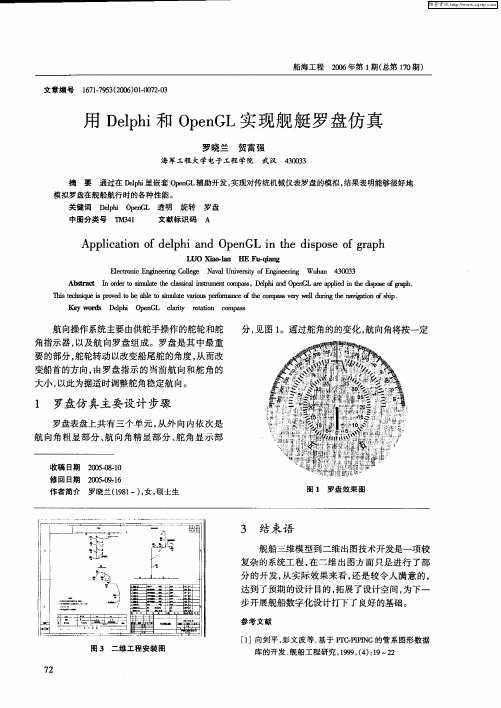
制, 即图片 的旋转。这里 选择 O eG实现 图片的 pn 1 旋转 。在D l i eh p 里嵌套 O eG_ , pn l]利用输入 的舵 角 1 和仿真的舰船航 向变化控制表盘中各组件转动 。
1 2 各 圆盘 函数关 系方程 .
合使用 , 最重要 的是在 Dl i eh p 里声 明及初 始化 , 一
般来说 , 相关网站 已提供编译好 的声明部分 , 可直
Ap lc to fd l h n e GL i h ip s fg a h p iain o ep ia d Op n n te d s o e o rp
LUO a - n HE - ln Xio l a Pu q a g
Eet n n | e o ee N vl nvrt o E 蹴 衄 l r i E gn 血gC l g aa U i sy f n co c e l e i
达到 了预期的设计 目的 , 拓展了设计空间。 为下一 步开展舰船数字化设计打下了良好 的基础 。
参考文献
[ ]向剑平 , 1 彭文波 等 . 基于 FE PPN I -IIG的管系 图形数据 图 3 二维工程安装 图
7 2
库 的开发 . 舰船工 程研究 ,9 9 ( ) 1 2 19 ,4 :9 2
O eG 作为一种三维软件工具包 , pn L 性能异常 优越。它具有建模 、 变换 、 光线处理 、 色彩处理等
Omega DRA-RTM-8模拟器用户指南说明书

Contents1. GENERAL DESCRIPTION2. MOUNTING INSTRUCTIONS3. REPLACING FUSES4. ASSEMBLY5. CURRENT INPUTS6. CONNECTING TRANSMITTERS TO THE MULTIPLEXER7. CONNECTING Pt-100 TO THE MULTIPLEXER8. CONNECTING THE MULTIPLEXER TO A PLC9. CONTROL9.1 Enable9.2 Address9.3 Address Polarity9.4 Control Tables10. CALIBRATION10.1 Calibration Procedure10.2 Calibration Tables10.2.1 "ZERO" - Coarse Calibration Tables10.2.2 "SPAN" - Coarse Calibration Tables11. MULTIDROP CONFIGURATION12. SPECIFICATIONS11. GENERAL DESCRIPTION2WARNING: Never install a fuse rated more than 800mA The DRA-RTM-8 is a multiplexer for 16 analog inputs - eight of which, marked 1-8, are direct inputs for Pt-100 sensors, while the remaining (9-16), are for 4-20mA current loops.The DRA-RTM-8 output format is a 4-20mA current loop, with a 28mA limitation.Each Pt-100 input has its own signal conditioner, allowing each input to be calibrated separately. Each signal conditioner includes six DIP switches for coarse calibration and two potentiometers for fine tuning.2. MOUNTING INSTRUCTIONSThe DRA-RTM-8 is designed for standard DIN rail mounting.Place the unit on the upper part of the mounting rail with the fastening tab facing down. Using a suitable flat screwdriver loosen the tab slightly and attach the unit to the rail. Once the tab is loosened, ensure that the unit is fastened securely in place.3. REPLACING FUSESTo replace a blown fuse, disassemble the unit as follows:a. Take off both terminal strips by removing the four screws at the edges. Note: This does not require disconnecting the cables connected to the strips.b. Remove the front panel using a suitable flat screwdriver. Press down gently on the plastic springloaded tabs located in the slots on either side of the unit.c. Disconnect the flat connectors which connects the front panel printed circuit.d. Replace the blown fuse.4. ASSEMBLYThe DRA-RTM-8 unit includes two printed circuit cards designated as P.N 7020 and P.N 7021. The two printed circuit cards should occupy the slots in the enclosure according to fig 1.3Insert the two printed cards into their slots.Connect the flat cable between them.Connect the front panel flat cables. Thepanel must be inserted into the grooves onboth sides of the case while pressing downuntil a distinct "click" is heard. Assembly iscompleted by laying the terminal strips inplace.Note: The terminal strips are polarized and must not be placed backwards.5. CURRENT INPUTSThe eight 4-20mA current inputs are marked as channels 9-16. These inputs are for current only. The "COM" input is the return for all the current channels. It is possible to connect any current source, as long as a closed loop is maintained.Figure 1.6. CONNECTING TRANSMITTERS TO THE MULTIPLEXER6.1 TWO WIRE TRANSMITTERA Two-Wire transmitter is connected so that itspositive terminal is connected to the positiveterminal of the power supply, and its negativeterminal is connected to the "I" terminal.(see fig 2)Figure 2.6.2 FOUR WIRE TRANSMITTERA Four-Wire transmitter is connected so that itspositive terminal is connected to the "I" terminal,and its negative terminal is connected to the"COM" terminal. (see fig 3)Figure 3.WARNING: Voltage sources should not be connected to the current inputs,as permanent damage might occur.4Figure 4.7. CONNECTING Pt-100 TO THE MULTIPLEXERThe Pt-100 probe should be connected according to fig 4. Thethree wires connecting the probe should be identical.The distance of the probe can be up to 200 meters.A shielded cable is recommended.The shield should be grounded at one point. When possible,connect the ground at the multiplexer's end.8. CONNECTING THE DRA-RTM-8 TO A PLCThe multiplexer output should be connected to 4-20mA input of the PLC analog module (see fig 5).The DRA-RTM-8 multiplexer generates the output current, therefore the PLC analog module should be configured for four wire transmitter connection.WARNING: NEVER apply 24Vdc to the DRA-RTM-8's +Io terminal as in two-wire connection, and make sure that the PLC's analog module is configured as a passive input.9. CONTROLThe DRA-RTM-8 unit is controlled via fouraddress lines and one E (Enable) line.The control terminals (Address andEnable), were designed to receive controlsignals from TTL levels up to 60V so thatalmost any PLC's DC output module canbe used. (see fig 5)Figure 5.9.1 ENABLEThe unit is enabled when a logical "1" (5V < E < 60V) is connected to the E Terminal. In a disabled state, the DRA-RTM-8 outputs no current and reflects a Hi-Z state. This feature allows the connection of several DRA-RTM-8 units by tying their outputs and control in parallel and addressing them by controlling the individual Enable terminals.9.2 ADDRESSThe required channel is selected byfour address lines.The operating voltages are:Logical "1" 5V < Vi < 60VLogical "0" 0V < Vi< 0.5V9.3 ADDRESS POLARITY (see fig 6)Address polarity is controlled by three internal pins and a jumper over two of them, located on PN 7021 printed circuit board, accessible behind the Enable terminal. The unit is supplied with the jumper set for "true high" control logic, i.e. "0000" selects channel #1, and "1111" selects channel #16.Moving the jumper to the second alternative, reverses the logic.Figure 6.Note: If the address contros voltages are generated from different power supplies, then its negative terminal should be connected to theDRA-TM-8's "COM" terminal.9.4 CONTROL TABLES9.4.1 "TRUE LOW" SETTINGADDRESS BUS E OUTPUTCHANNELA0A1A2A31 1 1 1 101111111111876541 1 1 x 111x11x11x111321NO OUTPUTADDRESS BUS E OUTPUTCHANNELA0A1A2A30 0 0 0 00111111111116151413120 0 0 x 111x11x11x11111109NO OUTPUT5ADDRESS BUS E/T OUTPUTCHANNELA0A1A2A31 1 1 1 1011111111119101112131 1 1 x 111x11x11x111141516TEST MODEADDRESS BUS E/T OUTPUTCHANNELA0A1A2A30 0 0 0 001111111111123450 0 0 x 111x11x11x111678TEST MODE9.4.2 "TRUE HIGH" SETTINGNote: The unit includes three internal potentiometers. These potentiometers are carefully adjusted and sealed in the factory. It is not recommended to alter these calibration potentiometers.10. CALIBRATIONTo calibrate the DRA-RTM-8, the limits must be defined.Tmin is the temperature at which the output current is 4mA.Tmax is the temperature at which the output current is 20mA.Tspan is the difference between Tmax and Tmin.10.1 CALIBRATION PROCEDUREa. Remove the terminal strips to get access to the coarse calibration switches.b. Set the channels DIP switches to the desired calibration ranges according to thecalibration tables.c. Re-install the terminals strips. The terminal strips are polarized and should bereturned to their original position.d. Connect a Pt-100 calibrator* set for Tmin to the proper input terminals.e. Apply the proper channel selection code by connecting those which accordingthe table should be "1" to the +PWR terminal.f. Start calibrating by adjusting the proper "Z" potentiometer to obtain an outputcurrent of 4.000mA.g. Set the calibrator for Tmax and adjust the "S" potentiometer to obtain an outputcurrent of 20.000mA.h. Repeat this procedure until satisfactory results are obtained.6* The calibrator is set according to DIN 43760 Pt-100 table (a = 0.00385)10.2 CALIBRATION TABLESNote: Logic state of "0" is when the DIP switch lever is down.10.2.1 "ZERO" - COARSE CALIBRATION TABLESZERO TEMP CCHANNELS 1-4SW5SW4 SW6-50 (10)8 (75)74 (140)139 (206)205 (272)270 (338)336 (404)401 (4701)1111111111100CHANNELS 5-8SW2SW3SW11111111111110010.2.2 "SPAN" - COARSE CALIBRATION TABLESSPAN CCHANNELS 1-4SW2SW3 SW150 (76)65 (115)110 (180)135 (225)215 (440)400 (8001)11111111CHANNELS 5-8SW5SW4SW6111111111i. Change the address to the next channel to be calibrated.j. Repeat steps b to h7RETURN REQUESTS / INQUIRIESDirect all warranty and repair requests/inquiries to the OMEGA Customer Service Department.BEFORE RETURNING ANY PRODUCT(S) TO OMEGA, PURCHASER MUST OBTAIN AN AUTHORIZED RETURN (AR) NUMBER FROM OMEGA’S CUSTOMER SERVICE DEPARTMENT (IN ORDER TO AVOID PROCESSING DELAYS). The assigned AR number should then be marked on the outside of the return package and on any correspondence.The purchaser is responsible for shipping charges, freight, insurance and proper packaging to prevent breakage in transit.OMEGA’s policy is to make running changes, not model changes, whenever an improvement is possible.This affords our customers the latest in technology and engineering.OMEGA is a registered trademark of OMEGA ENGINEERING, INC.© Copyright 1996 OMEGA ENGINEERING, INC. All rights reserved. This document may not be copied,photocopied, reproduced, translated, or reduced to any electronic medium or machine-readable form, i n w h o l e o r i n p a r t , w i t h o u t p r i o r w r i t t e n c o n s e n t o f O M E G A E N G I N E E R I N G , I N C.FOR WARRANTY RETURNS, please have thefollowing information available BEFORE contactingOMEGA:1. P .O. number under which the product wasPURCHASED,2. Model and serial number of the product underwarranty, and3. Repair instructions and/or specific problemsrelative to the product.FOR NON-WARRANTY REPAIRS, consult OMEGA for current repair charges. Have the following information available BEFORE contacting OMEGA:1. P .O. number to cover the COST of the repair,2. Model and serial number of product, and 3. Repair instructions and/or specific problems relative to the product.WARRANTY/DISCLAIMEROMEGA ENGINEERING, INC. warrants this unit to be free of defects in materials and workmanship for a period of 13 months from date of purchase. OMEGA Warranty adds an additional one (1) month grace period to the normal one (1) year product warranty to cover handling and shipping time. This ensures that OMEGA’s customers receive maximum coverage on each product. If the unit should malfunction,it must be returned to the factory for evaluation. OMEGA’s Customer Service Department will issue an Authorized Return (AR) number immediately upon phone or written request. Upon examination by OMEGA, if the unit is found to be defective it will be repaired or replaced at no charge. OMEGA’s WARRANTY does not apply to defects resulting from any action of the purchaser, including but not limited to mishandling, improper interfacing,operation outside of design limits, improper repair, or unauthorized modification. This WARRANTY is VOID if the unit shows evidence of having been tampered with or shows evidence of being damaged as a result of excessive corrosion; or current, heat, moisture or vibration; improper specification; misapplication; misuse or other operating conditions outside of OMEGA’s control. Components which wear are not warranted, including but not limited to contact points, fuses, and triacs.OMEGA is pleased to offer suggestions on the use of its various products. However,OMEGA neither assumes responsibility for any omissions or errors nor assumes liability for any damages that result from the use of its products in accordance with information provided by OMEGA, either verbal or written. OMEGA warrants only that the parts manufactured by it will be as specified and free of defects.OMEGA MAKES NO OTHER WARRANTIES OR REPRESENTATIONS OF ANY KIND WHATSOEVER, EXPRESSED OR IMPLIED, EXCEPT THAT OF TITLE, AND ALL IMPLIED WARRANTIES INCLUDING ANY WARRANTY OF MERCHANTABILITY AND FITNESS FOR A PARTICULAR PURPOSE ARE HEREBY DISCLAIMED. LIMITATION OF LIABILITY: The remedies of purchaser set forth herein are exclusive and the total liability of OMEGA with respect to this order, whether based on contract,warranty, negligence, indemnification, strict liability or otherwise, shall not exceed the purchase price of the component upon which liability is based. In no event shall OMEGA be liable for consequential, incidental or special damages.CONDITIONS: Equipment sold by OMEGA is not intended to be used, nor shall it be used: (1) as a “Basic Component” under 10 CFR 21 (NRC), used in or with any nuclear installation or activity; or (2) in medical applications or used on humans. Should any Product(s) be used in or with any nuclear installation or activity,medical application, used on humans, or misused in any way, OMEGA assumes no responsibility as set forth in our basic WARRANTY / DISCLAIMER language, and additionally, purchaser will indemnify OMEGA and hold OMEGA harmless from any liability or d a m a g e w h a t s o e v e r a r i s i n g o u t o f t h e u s e o f t h e P r o d u c t (s ) i n s u c h a m a n n e r.Where Do I Find Everything I Need forProcess Measurement and Control?OMEGA…Of Course!TEMPERATUREߜ Thermocouple, RTD & Thermistor Probes,Connectors, Panels & Assembliesߜ Wire: Thermocouple, RTD & Thermistorߜ Calibrators & Ice Point Referencesߜ Recorders, Controllers & Process Monitorsߜ Infrared PyrometersPRESSURE, STRAIN AND FORCEߜ Transducers & Strain Gaugesߜ Load Cells & Pressure Gaugesߜ Displacement Transducersߜ Instrumentation & AccessoriesFLOW/LEVELߜ Rotameters, Gas Mass Flowmeters & Flow Computersߜ Air Velocity Indicatorsߜ Turbine/Paddlewheel Systemsߜ Totalizers & Batch ControllerspH/CONDUCTIVITYߜ pH Electrodes, Testers & Accessoriesߜ Benchtop/Laboratory Metersߜ Controllers, Calibrators, Simulators & Pumpsߜ Industrial pH & Conductivity EquipmentDATA ACQUISITIONߜ Data Acquisition & Engineering Softwareߜ Communications-Based Acquisition Systemsߜ Plug-in Cards for Apple, IBM & Compatiblesߜ Datalogging Systemsߜ Recorders, Printers & PlottersHEATERSߜ Heating Cableߜ Cartridge & Strip Heatersߜ Immersion & Band Heatersߜ Flexible Heatersߜ Laboratory HeatersENVIRONMENTALMONITORING AND CONTROLߜ Metering & Control Instrumentationߜ Refractometersߜ Pumps & Tubingߜ Air, Soil & Water Monitorsߜ Industrial Water & Wastewater Treatmentߜ pH, Conductivity & Dissolved Oxygen Instruments M2614/0197。
凡尔纳水晶瀑布缆索系统安装 维护 使用手册说明书

INSTALLATION/CARE/USE MANUALIMPORTANT! INSTALLER PLEASE NOTE.ALL SERVICE TO BE PERFORMED BY AN AUTHORIZED SERVICE PERSONTHE GROUNDING OF ELECTRICAL EQUIPMENT SUCH AS TELEPHONE, COMPUTERS, ETC. TO WATER LINES IS A COMMON PROCEDURE. THIS GROUNDING MAY BE IN THE BUILDING OR MAY OCCUR AWAY FROM THE BUILDING. THIS GROUNDING CAN CAUSE ELECTRICAL FEEDBACK INTO A FOUNTAIN, CREATING AN ELECTROLYSIS WHICH CAUSES A METALLIC TASTE OR AN INCREASE IN THE METAL CONTENT OF THE WATER. THIS CONDITION IS AVOIDABLE BY USING THE PROPER MATERIALS AS INDICATED. ANY DRAIN FITTINGS PROVIDED BY THE INSTALLER SHOULD BE MADE OF PLASTIC TO ELECTRICALLY ISOLATE THE FOUNTAIN FROM THE BUILDING PLUMBING SYSTEM.SIDE VIEWFRONT VIEWASSEMBLY1.Assemble support brackets to the fountain by aligning holes in bracket with holes in cooler and fastening with(4) #10 screws provided.2.Attach bubbler to fountain by inserting bubbler nipple through the hole in the cooler top and securingwith the washer and nut provided.INSTALLATION1.This fountain is to be mounted on a smooth, flat, finished wall surface, with adequate support structure.2.Establish rim height fountain is to be mounted.3.Refer to rough-in for plumbing.4.Locate and install trap. (Trap not included).5.Install shut-off valve on building water supply. (Shut off valve not furnished).6.Locate and install hanger bracket using 1/4" (10mm) lag screws or bolts. (Not included).7.Install and center fountain on hanger bracket by slipping the back edge of the cooler top over theflange on the hanger bracket. Secure fountain using 1/4" (10mm) minimum lag screws or bolts (Notincluded).CAUTION: This fountain is rated for inlet water pressure of 20-105 psi. Should the inlet water supply exceed 105 psi, a pressure reducing regulator should be used.8.Connect fountain to building supply line by running a 3/8" (10mm) water line between the shut-offvalve and fountain.9.Turn "ON" water supply and check all connections for leaks.10.Adjust bubbler stream height. (See instructions below).TROUBLE SHOOTING AND MAINTENANCEOrifice Assy: Mineral deposits on orifice can cause water flow to spurt or not regulate. Mineral deposits may be removed from the orifice with a small round file not over 1/8" diameter or small diameter wire.CAUTION: DO NOT file or cut orifice material.Stream Regulator: If orifice is clean, regulate flow as stated below. If replacement is necessary, see parts list for correct regulator part number.STREAM HEIGHT ADJUSTMENT: Stream height is factory setat 45-50 PSI. If supply pressure varies greatly from this, removeitems 11, and 12 (See figure 2) from bubbler assembly andadjust the screw on the regulator (Item 15). Clockwise adjust-ment will raise stream height and counterclockwise will lowerthe stream height. A stream height of 1-1/2" (38mm) is recom-mended.FIG. 1ITEMIZED PARTS LISTITEM NO.P ART NO.DESCRIPTION28057C 580001555800015427238C 40294C 70208C 74070020LK14210031C 10032274056040048C 40089C 40322C 45675C 61313C 70012C 72460042A54800A5488812345678910111213141516171819Basin Assy.Bracket - Support LH Bracket - Support RH Bracket - Wall HangerT ailpipe - 1-1/4 O.D. x 4.00 IN.Mach. Screw 10-24x3/810-24 Hex Nuts (N/S)Bubbler AssemblyRetaining Nut 1 1/8-24Gasket ButtonCover Nut 1 1/8-24Orifice Assembly Bubbler Body RegulatorLock Nut 3/8-18Metal Washer Nipple ScreenPRINTED IN U.S.A.1See Fig. 24FIG . 2FIG. 363528141316101918179121115 800-518-5388。
基于飞行力学的惯导轨迹发生器及其在半实物仿真中的应用--欢迎下载并发表

收稿日期:201X-xx-xx ; 修回日期:201X-xx-xx 基金项目:国家自然科学基金(90816027);航空科学基金(20135853037);航天技术支撑基金(2013-HT-XGD-15)基于飞行力学的惯导轨迹发生器及其在半实物仿真中的应用陈凯,卫凤,张前程,于云峰,闫杰 (西北工业大学 航天学院,西安710072)摘 要:讨论了在高超声速飞行器半实物仿真中,使用飞行器六自由度模型生成捷联惯导轨迹发生器的方案,使半实物仿真中的捷联惯导系统与飞行力学模型和飞行控制系统有机地融合到一起。
介绍了六自由度模型的坐标系定义,描述了发射坐标系下由32个方程组成的高精度六自由度模型。
指出了六自由度模型中惯性器件测量的比力和角速率理论值,比力和角速率是由飞行器飞控系统作用后所产生各种力和力矩的综合结果,而不同于传统轨迹发生器中由事先设定的速度和姿态变换获得。
将发射坐标系下的导航信息推导到高超声速飞行器需求的当地水平导航坐标系下。
高超声速飞行器数字仿真表明,提出的轨迹发生器满足半实物仿真算法精度要求;半实物仿真表明,导航系统与六自由度模型、飞行控制与制导系统能够有机结合,导航结果精度满足指标要求,支撑了高超声速飞行器飞控系统性能指标评估。
关键词:轨迹发生器;捷联惯导;六自由度模型;高超声速飞行器;半实物仿真 中图分类号:V249.3文献标识码:A 文章编号:Trajectory Generator of Strapdown Inertial Navigation System on Flight Dy-namics with Application in Hardware-in-the-Loop SimulationCHEN Kai, WEI Feng, ZHANG Qian-cheng, YU Yun-feng, Y AN Jie(School of Astronautics, Northwestern Polytechnical University, Xi ’an 710072, China )Abstract : How to generate trajectory profile of strapdown inertial navigation system (SINS) based on flight dy-namics is discussed in the hypersonic vehicle hardware-in-the-loop (HWIL) simulation, which makes SINS work together in harmony with hypersonic vehicle six-degree-of-freedom (6DoF) model and flight control and guidance system. Firstly, the definition of coordinate system in 6DoF model is introduced. Then the high precision 6DoF model consists of 32 equations is described in launch centered earth-fixed (LCEF) coordinate system. The theoreti-cal value of the specific force and the angular velocity measured by inertial measurement unit (IMU) in 6DoF mod-el is pointed out. The specific force and the angular velocity is a combined result of a variety of forces and mo-ments by flight control system during flight, which is different with a traditional trajectory generator whose specific force and angular velocity is obtained from velocity and attitude change sets in advance. The navigation informa-tion in LCEF frame is converted to local ENU frame to meet hypersonic vehicle demand. The hypersonic vehicle digital simulation result reveals that the 6DoF model, the flight control and guidance system, and SINS can work together. The HWIL simulation indicates that the accuracy of SINS satisfies the requirement of hypersonic vehicle and can support the evaluation of the hypersonic vehicle flight control system performance. Keywords :Trajectory generator; Strapdown inertial navigation system (SINS); Six-degree-of-freedom model; Hypersonic vehicle; Hardware-in-the-loop (HWIL) simulation0 引 言捷联惯导系统具有导航信息全、自主性高、连续性好、更新率高等优点,是飞行器飞行控制系统的关键部件之一,各种飞行器都在广泛使用。
诺亚科技 DX-7 模拟器用户指南说明书

Icon Algorithm Parameter Sine Phase distortion Sqr/Pulse PWM Saw/Tri Wave shape Quad sawPhase spread Additive even (7 osc) Harmonics Additive odd (7 osc) Harmonics Additive all (7 osc) Harmonics Unison square (3 osc) Spread Unison saw (5 osc) Spread Bit-crushed saw Bit resolution Bit-crushed sine Bit resolution Self-sync sqr Carrier Frequency Self-sync pulse Carrier Frequency Self-sync saw Carrier Frequency Self-sync tri Carrier FrequencySelf-sync sineCarrier FrequencyVCO MODE ALGORITHMSRing modulator Carrier Frequency Noise + low-pass Filter resonance Noise + bandpass Filter bandwidthNoise + resonatorFilter gainLFO MODE ALGORITHMSIcon Algorithm Parameter Saw/triangle Slope Square/pulse PWMSine Phase distortionBrownian S/HRandom level maximum deviation Randomly timed S/H Time randomness Brownian vectors Random level maximum deviationRandomly timed vectorsTime randomnessQuantize Icon Quarter tones ¼ Semitones ½ Diatonic Di Major M Minorm Natural Minor nm Pentatonic Pe Spanish Sp Gamelan Ga In Sen IS Hirajoshi Hi Blues B L Chinese Ch Hungarian Hu Octatonic 8n Hexatonic 6n Thirds3”VCO QUANTIZERLFO ctrl +CV 16x /1.5 12x /2 9x /3 8x /4 6x /6 4x /8 3x /9 2x /12 1.5x /16 1x /32 /48/64LFO div/multKlavisTwin wavesDual VCO/LFOFifths5” Octaves Oc Just intonation 12 19 tones19FRONT PANELControlsOSC2 Switches between Osc 1 & 2 and allocates buttons, knobs and display to the first or second oscillator. When Osc2 LED is on, the second oscillator is selected. LFO/AM sets the LFO/VCO mode. When on, the current oscil-lator is in LFO mode and the FM jack becomes AM (VCA). Qtz/Clk accesses the quantizer when in VCO mode or external clocking when in LFO mode. When LED is on, quantize or external clocking is active.Sync is about VCO or LFO wave sync (restart). When LED is on, sync is enabled.Algo when encoder is pressed, the LED flashes; if then turned, it selects one of the algorithms. When turned with LED off, it changes the Parameter related to the current algorithm. Coarse sets the VCO pitch or LFO rate. With external LFO clocking active, it controls the mult/div ratio.Fine/Level sets the tuning in VCO mode or output level in LFO mode.A long press on the encoder brings a scrolling help text !Inputs & outputsV.Oct 1 & 2 drive the pitch in VCO mode, and rate or clock ratio in LFO mode. Param 1 & 2 control the dynamic parameter relating to the current algorithm. Sync/Clk can be Sync or clock input for osc 1 and/or 2. This jack is shared by both sections and enabled separately.Out 1 & 2 wave outputs. Section 1 only:FM/AM can be set into BZX-FM, Lin-FM, VCA, algorithm selection or quantizer base note setting.The [square] 1 out is a sub-octave in VCO mode or trigger pulse at LFO rate.USAGEThe module contains two sections/oscillators, each individu-ally set as VCO or LFO. VCO and LFO modes have their dedi-cated selection of synthesis algorithms.Each algorithm has a specific dynamic parameter that can be changed with the encoder and via CV from the Param jack. White LEDs next to the potentiometers tell when the knob is active and its cursor reflects the actual setting.Pressing a button brings on the editing, which is done with the encoder. Validation is done by pressing the encoder. Settings are maintained and recalled after power cycle. Within a section in LFO mode, Sync and Clk control are exclu-sive, but each section can activate any one of these. In VCO mode there is no Clock setting; instead comes a quantizer with various scales. Sync restarts the wave. With both sections in VCO mode, a long press on Osc2 offers 3 uses of the V.Oct inputs:∙ Separate - each input drives its own oscillator∙ Added - the sum of both inputs is sent to both oscillators ∙ Offset - V.Oct 1 drives both oscillators; V.Oct 2 comes in addition on oscillator 2.SUPPORT & ADDITIONAL INFOThe complete users manual is available at:/support Contactus:******************TW-V2 - Copyright 2019 - Diagonal ElectronicsINSTALLATIONEnsure that there is enough power left to supply this module. Beware of the orientation; the stripe on the ribbon cable should match a similar stripe for the –12 (minus 12 Volts) indication on your supply board connector. Supply rail Current draw+12V 46 mA -12V 18 mA +5V0 mARE A DM EF I RST。
- 1、下载文档前请自行甄别文档内容的完整性,平台不提供额外的编辑、内容补充、找答案等附加服务。
- 2、"仅部分预览"的文档,不可在线预览部分如存在完整性等问题,可反馈申请退款(可完整预览的文档不适用该条件!)。
- 3、如文档侵犯您的权益,请联系客服反馈,我们会尽快为您处理(人工客服工作时间:9:00-18:30)。
海神(POSEIDON):Eldes可编程导引头模拟器
海神被认为是反舰导弹(AShm)电子对抗效能验证的最佳解决方案!其特点、优势及应用范围如下:
1、特点:
●移动、可编程、半实物仿真(HWIL)的低空导引头模拟器;
●在海军试验中,用于电子支援/电子对抗/电子反对抗措施的测试与评估;
●强大的数据记录能力、采用专业软件分析;
●低成本舰载电子战验证方案;
●从X波段到Ka波段的广域有效带宽E;
●采用软件定义雷达技术,用户可通过图形界面轻松编程,以模拟反舰导弹的任何行
动;
●波形可编程的固态发射机;
●可编程的数字接收机;
●实时显示包括A\B\C范围、跟踪错误、频谱等信息;
●轻量级、低功率,便于可移动操作。
2、优势:
➢减少了舰载电子对抗评估的时间和相关成本;
➢提升了舰载电子对抗试验的准确性;
➢允许对电子对抗库进行调整完善;
➢针对精确仿真威胁,可进行电子战操作有关的逼真训练。
3、应用:
●专用试验中的舰载电子对抗评估;
●反舰导弹导引头的反对抗措施的开发与验证;
●电子战操作员培训;
●电子战装备的定期效能检查。
***基础介绍***
电子对抗效果的验证,尤其是针对反舰导弹、低空或其他类型火控雷达缺少简便的方案,为了达到这个目标,在电子战试验中,仪器化导引头经常得以应用。
但此方法有其局限性,首先,大多数情况下,他们并不能代表真正的威胁,再者,它们是静态的,不能根据距离与轨道的变化生成动态实时信号,这样的系统仅仅能够模拟一种类型的威胁,有时只能生成传输脉冲,所以对于实时威胁或导引头的接收与处理链路来说,无法准确评估对抗措施的实际效果。
因此只有电子支援部分能够被验证,而电子对抗效果无法评估。
借助海神-Eldes可编程导引头模拟器,能够消除或至少极大的减少这些限制,因为采用了软件定义雷达技术(SDR)。
海神是一个半实物仿真系统,它包括一个天线(拥有合理的扫描控制),一个可编程波形固态发射机、射频前端、一个可编程数字化接收机、雷达信号处理器以及一个通用型显控面板。
图1 海神(POSEIDON)系统组成图
所有的硬件都包含在一个易于运输的加固机架中,用于在操作场景或电子战试验范围内快速部署,以便在相关环境中进行特定和详尽的试验。
用户根据收集的电子情报,利用友好的图形用户接口,定义潜在威胁雷达的发射与接受参数,海神能够对实时创建的雷达模型进行仿真。
所以发射机与天线的运动情况,以及电子反对抗相关的雷达接收/处理链路逻辑能够被复制。
图2 仿真图形界面
经目标反射的实际表面回波,通过真实天线接收到,被海神通过方位、角度进行侦察与跟踪。
试验过程中电子战系统能够对威胁进行检测与分类,并依据样本库对此进行反应,生成电子对抗措施。
这种方法能够在实际场景下对敌方雷达系统或导引头的精确与逼真复制,实现了对电子对抗装备和函数库的验证,从而允许在测试环境中对电子战装备进行调整与检验。
测试结果能够实时显示在图形交互人机界面中,同时所有测量数据均能够被存储与回放,以达到出具任务报告和效果分析的目的。
海神能够模拟火控雷达和动态导引头,还能用于检测新体制雷达和相关电子反对抗技术, 为雷达系统工程学提供有价值的支持。
***工作原理***
在进行试验的区域内,海神系统被安装在移动平台上(庇护所、房车、卡车),并安置在海岸边一个便捷的位置。
试验中当平台被海神占线时(准确说是被编程用于模拟潜在威胁),它仍然能够识别威胁并做出反应以生成对抗措施。
海神系统操作员能够实时观察并记录接收到的数据,例如目标回波信号、重叠的干扰源/欺骗,模拟导引头的跟踪状态、相关跟踪错误,此外相关的干扰源信号频谱也能被可视化展现。
以上这些信息都可以支撑用户评估针对模拟威胁的电子对抗措施质量,从而改善电子对抗措施库。
根据所选择的威胁目标特征,用户能够通过图形界面,轻松的生成雷达模型库。
图3 目标跟踪显示
图4 噪声干扰效果。