Mechanical Probing Authorship
机械原理外文文献

机械原理外文文献IntroductionMechanical principles are fundamental concepts in engineering and physics that are essential for understanding the behavior and operation of machines and mechanical systems. These principles are the building blocks of mechanical engineering and are used to design, analyze, and optimize mechanical devices and systems. In this paper, we will discuss some of the key mechanical principles, including force, motion, energy, and momentum, and their applications in various mechanical systems.Force and MotionForce and motion are two of the most fundamental concepts in mechanical engineering. Force is defined as any interaction that causes an object to undergo a change in speed, direction, or shape. In mechanical systems, forces are applied to machines and mechanical components to produce motion or to resist motion. The study of forces and their effects on motion is known as dynamics, and it is essential for understanding the behavior of mechanical systems.One of the key laws of motion is Newton's first law, which states that an object at rest will remain at rest, and an object in motion will remain in motion, unless acted upon by an external force. This law is used to analyze the behavior of mechanical systems and to design machines that can produce or resist motion.Energy and WorkEnergy is another critical concept in mechanical engineering and is defined as the ability to do work. Work, in the context of mechanical systems, is the transfer of energy from one object to another through the application of a force over a distance. The study of energy and work is essential for designing and analyzing mechanical systems that involve the conversion and transfer of energy, such as engines, turbines, and pumps.One of the fundamental principles of energy is the conservation of energy, which states that the total energy in a closed system remains constant over time. This principle is used to analyze the behavior of mechanical systems and to design machines that can efficiently convert and transfer energy.Momentum and ImpulseMomentum is a measure of an object's motion and is defined as the product of its mass and velocity. In mechanical systems, momentum is essential for understanding the behavior of moving objects and for designing machines that can produce or resist motion. Impulse is the change in momentum of an object due to the application of a force over a period of time, and it is used to analyze the behavior of mechanical systems during collisions and other dynamic events.One of the key principles of momentum and impulse is the conservation of momentum, which states that the total momentum in a closed system remains constant over time. This principle is used to analyze the behavior of mechanical systems during collisions and to design machines that can efficiently transfer momentum.ApplicationsThe principles of force, motion, energy, and momentum are used in a wide range of mechanical systems and devices. For example, in the design of engines and turbines, the principles of energy and work are used to optimize the conversion of energy from one form to another. In the design of vehicles and transportation systems, the principles of force and motion are used to analyze the behavior of moving objects and to optimize the performance of mechanical components. In the design of robotics and automation systems, the principles of force, motion, energy, and momentum are used to optimize the operation of mechanical devices and to ensure the safety and reliability of the systems.ConclusionMechanical principles are essential for understanding the behavior and operation of machines and mechanical systems. The concepts of force, motion, energy, and momentum are fundamental to the design, analysis, and optimization of mechanical devices and systems. These principles are used in a wide range of applications, from engines and turbines to vehicles and transportation systems, to robotics and automation systems. By understanding and applying these principles, engineers can design machines that are efficient, reliable, and safe, and that can meet the demands of modern industry and technology.Overall, the principles of force, motion, energy, and momentum are the foundation of mechanical engineering and are essential for the development of new technologies and innovations in the field.。
机械设计过程外文文献翻译、中英文翻译

附录英文Machine design processThe machine is the organization with other components combinations, transforms,the transmission or using the energ,the strength or the movementexample for the beneficial use has the engine.the turbine wheel,the vehicles.the hoist,the printer,the washer and the movie camera Many is suitable tbr themachine design principle and the strength law also is suitable to is not thegenuine machine finished product.the driven wheel hub and the file cabinet tothe measuring appl iance and the nuclear pressure vessel.”Machine designt thisterminology compared to”machine design”more generalized,it including machine design.But regarding certain instruments.1ike uses to determine hot,the mobile line and the volume thermal energy as well as the fluid aspect question needs alone to consider.But when machine design must consider themovement and the structure aspect question as well as preserved and the sealstipulation.In the mechanical engineering domain and all that project domainapplication machine design,all need such as mechanism and so on the svdtch,cam,valve,vessel and mixer.The design beginning tO being true or the imagination need.The existing instrument possibly needs in the durability,the efficiency,the weight,the speedor the cost performs to improve.]he possible need new instrument tO completebefore made the function by the person.1ike t was abundant Assembly or maintenance.After the goal completely or partially determines,the design nextstep is the idea carl complete needs the ffmction the organization and its thearrangement for this,the free hand drawing schematic diagram value is enormous,it not only takes a person idea the recording and the auxiliary.methodwhich if the other people discusses,moreover especially is suitable for with ownidea exchange,also needs to concern as the creative mentality stimulant to thepart widespread knowledge,because a new machine frequently by knew very well each kind of components rearrange or the replace become,perhaps changedthe size and the material.Regardless of after idea process or,a designer callcarry on fast either the sketchy computation or the analysis determines thegeneral size and the feasibility.After about need or may use the spatial meteidea determination,may start according to the proportion picture schematicdiagram.When several components approximate shapes and several sizes come out,the analysis was allowed truly to start.The analysis goal lies in enable it to havesatisfying or the superior performance,as well as will seek the best proportionand the size under the smallest weight security and the durability and thecompetitive cost designer for each essential load bearing section,as well asseveral components intensities balance then choice material and processingmethod.These important goals only have through only then may obtain based on the mechanism analysis,like about reacting force and friction most superioruse principie of statics;About inertia,acceleration and energy principle ofdynamics:About stress and deflection material elasticity and intensity principle;About material physical behavior principle;About lubrication and water poweractuation hydromechanics principle.The analysis may identical engineer whicharranges by the idea machinery do,or makes the analysis in the big company bythe independent analysis department or the research group the result,possibleneed new arrangement and new size.No matter is officially does orunofficialdoes,supposes Japan is relapse and the cooperation process.the analysis staffmay play the role to all stages but not merely is he stage.Some design criteriaIn this part,some people suggested carries on the analysis using the creative manner,this kind of analysis may cause the significant improvement aswell as to the spare product idea and the consummation,the product functionmore.more economical,is perhaps more durable. The creation stage does notneed is at first and the independent stage.Alttlough the analysis staff possiblycertainlv is not responsible for the entire design,but he not meyely is can fromthe numeral proposc wants question correct answer which he soIVes,not merelyis Droduces the stress value,the size or the work limit. He may propose a morewidespread opinion,in order to improvement standard or plan. Because beforethe analysis or in the analysis process,he can familiar install and its the workingcondition.he is in an idea to prepare chooses the plan the rantage Poinl.Best hecan propose the suggestion transfigure eliminates the moment of force or thestress concentration,but was not the permission constructs has the blgsectlonand the excessively many dynamic loads organization should better be he discards his careful desi{;n but is not afterwards saw the machinery discarded.In order to stimulate the creative thought,below suggested designs thepersonnel and the analysis staff uses the criterion.The first 6 criteria especially are suitable for the analysis staff,although he possibly involves to possesses this l o items.1.Creatively the use needs the physical performance and the control doesnot need.2.Knows the practical load and its the importance.3.D00s not consider the function load in advance.4.Invents the more advantageous loading environment.5.Provides the minimurn weight the most advantageous stress distributionand the rigidity.6.uses the fundamental equation computation proportion and causes thesize optimization.7.The selection material obtains the perlbrmance combination.8.In between spare parts and integrated components carefid choice. 9.Revisions functional design adapts the production process and reduces thecost.10.In the consideration assembly causes the part pintpointing and mutuallydoes not disturb.Designs the personnel to have in such domain,like the statics,the inematics,dynamics and the materials mechanics have the good accomplishment,in addition.but also must familiar make the material and themanufacture craft.Designs the personnel to have to be able to combine allcollrelations the fact,carries on teaches Wei.the manufacture schematic diagramand the charting comes the manufacture request totransmit the workshop. Any product design one of first step of work is the choice uses in to makeeach part the material.Today design personnel may obtain innumerably.When choice,the product function,the outward appearance,the material cost and theproduction cost very are all important.Before any computation must carefullyappraise the material the performance.It is the necessary careful computation toguarantee the design the validity The computation ever does not appear on thechart,but is saved by ten each kind of reason.Once any part expires,had makeclear when is designing at first this had the flaw the components has made any;Moreover,。
frontiers of mechanical engineering 模板

frontiers of mechanical engineering 模板Frontiers of Mechanical Engineering: Pioneering Innovations in the FieldMechanical engineering is a vibrant and ever-evolving discipline that plays a crucial role in advancing various industries. In this article, we will explore the frontiers of mechanical engineering and highlight some of the groundbreaking innovations that have emerged in recent years.One area where mechanical engineering is making significant strides is in the field of robotics. Researchers and engineers are continuously working towards developing intelligent and autonomous robots that can perform complex tasks with precision and efficiency. These robots have the potential to revolutionize manufacturing processes, healthcare systems, and even exploration of uncharted territories.Another frontier in mechanical engineering lies in the development of advanced materials. Engineers are now working on creating materials with unique properties like high strength, lightweight, and enhanced durability. These materials have the potential to revolutionize industries such as aerospace, automotive, and renewable energy by improving performance and efficiency.Moreover, the field of nanotechnology is offering exciting opportunities for mechanical engineers to push the boundaries of innovation. By manipulating materials at the nanoscale, engineers can create new materials with improved properties. Nanotechnology has the potential to impact various sectors, including electronics, medicine, and environmental conservation.The growing concern for sustainability has also pushed mechanical engineering to explore new frontiers. Engineers are developing renewable energy technologies, such as wind turbines and solar panels, to reduce the dependence on fossil fuels and mitigateclimate change. Additionally, advancements in energy storage systems are essential for overcoming the intermittent nature of renewable energy sources.The integration of digital technologies, such as artificial intelligence and the Internet of Things, represents another frontier in mechanical engineering. By combining mechanical systems with intelligent algorithms, engineers can optimize performance, enable predictive maintenance, and enhance overall efficiency. This integration has the potential to revolutionize industries ranging from transportation to healthcare.In conclusion, frontiers of mechanical engineering encompass a wide range of areas, from robotics and advanced materials to nanotechnology and sustainability. The continuous advancements in these fields have the potential to revolutionize various industries and improve the quality of life for people around the world. With the pace of innovation accelerating, mechanical engineering is poised to play a vital role in shaping the future.。
机械类外文翻译外文文献英文文献扭矩过载保护器
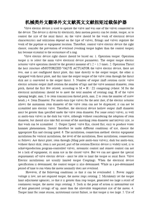
机械类外文翻译外文文献英文文献扭矩过载保护器Valve electric device is used to operate the valve and was one of the valves connected to the device. The device is driven by electricity, their motion process can be stroke, torque, or to control the size of the axial thrust. As the valve should be the work of electrical device characteristics and utilization depend on the type of valves, fittings and valves regulate the work of the pipeline or equipment location. Therefore, control valve electric device the right choice; consider the prevention of overload (working torque higher than the control torque) has become essential to the occurrence of a ring.Valve electric device right choice should be based on: 1. Operation torque: Operation torque is to select the main valve electrical device parameters. The output torque electric actuator valve operation should be the greatest moment of 1.2 ~ 1.5 times. 2. Operation Thrust: the host structure ofMOTORIZED V ALVE ACTUATOR the valve electric device, there are two, one is not configured thrust plate, this time directly to the output torque; the other is equipped with thrust plate, and this time the output torque of the valve stem through the thrust disk nut is converted to the output thrust. 3. Number of output shaft rotation circle: valve electric actuator output shaft rotation the number of laps and the valve nominal diameter, stem pitch, thread the first few related, according to M = H / ZS computing (where: M for the electrical installations should be to meet the total number of rotating ring; H of the valve opening height, mm; S to stem transmission thread pitch, mm; Z to stem the number of screw heads.) 4. Stem Diameter: For multi-turn type valves for the next shot, if the electric actuator allows the maximum stem diameter of the valve stem can not be dispensed, it can not be assembled into electric valve. Therefore, the electrical device hollow output shaft diameter must be greater than specified under the valve stem diameter. For some rotary valves, as well as multi-turn valves in the dark bar valve, although without considering the adoption of stem diameter, but should also take full account of the matching stem diameter and keyway size, so that work can be assembled . 5. Output Speed: valve Kai, closed fast, easy to produce water hammer phenomenon. Should therefore be under different conditions of use, choose the appropriate Kai and closing speed. 6. The installation, connection method: electric equipment installation for vertical installation, the level of the installation, floor installation; connections as follows: Are thrust plate; stem through (Ming pole multi-turn valves); dark bar multi-turn; without thrust disk; stem is not passed; part of the rotation Electric device is widely used, is to achieveproduction program-controlled valves, automatic control and remote control can not be a lack of equipment, its main use in the closed valve. But we can not ignore the special requirements of valve electric device - must be able to limit the torque or axial force. Valve Electric installations are usually limited torque Couplings. When the electrical device specification is determined, the control torque is also determined. While in a pre-determined period of time to run when the motor normally does not overload.However, if the following conditions so that it can be overloaded: 1. Power supply voltage is low, are not required torque, the motor stops rotating. 2. Mistakenly set the torque limit adjustment agencies, so that it is greater than stop torque, generated too large a result of continuous torque, the motor stops rotating. 3. Such as the point of action as intermittent use of heat generated savings of up, more than the allowable temperature rise of the motor. 4. Torque limit for some reason, institutional circuit failure, so that torque is too large. 5. Use ofenvironmental temperature is too high, relative to the heat capacity of the motor down. The above is the excessive number of reasons, for these reasons should be generated by motor overheating in advance, taking into account, and to take measures to prevent overheating. In the past to protect the motor way is to use fuses, overcurrent relays, thermal relays, thermostats, etc., but these approaches also have their pros and cons of this change for the electrical device load devices, is absolutely reliable protection method is not. Must therefore take all methods combined approach. However, as the load on each electrical device is different, it is difficult to propose a unified approach. In most cases, but generally, you can also find common ground.Overload protection taken by the way, be grouped into two types: 1. Changes in input current to the motor to judge; 2. To judge the heat of the motor itself. These two methods, regardless of the kind production Summarize of motor thermal capacity must take into account the given time margin. If a single way that will make the heat capacity characteristics of the motor line is difficult. Therefore, over-load should be selected according to the reasons for the action can be a reliable method - combination of complex ways in order to achieve a comprehensive over-load protection. Rotork electric actuator motor, its embedded in the windings in the motor insulation level consistent with the thermostat, when the reach the rated temperature, motor control loop will be cut off. Thermostat heat capacity is small in itself, and its time-limited features is the motor heat capacity characteristics of the decision, so this is a reliable method.The basic method of overload protection are: 1. Continuous operation of motor jog operation, or overload protection with a thermostat; 2. Locked-rotor protection of motor thermal relay 3. Pairs of short circuit faults using fuse or overcurrent relays. Valve electric device to prevent overload of the right choice and is very much related and should pay attention to.In consideration of economic aspects limiting torques is a continuous challenge when developing Torque Limiters as an overload protection. The new generation of the backlash-free Torque Limiters. The new generation of the backlash-free Torque Limiters has been designed for being used in power-transmission and servo applications. Important requirements such as being backlash-free, short reaction times and long service life have been further optimized. The constructive benefit is ensured through fast availability of applications after a crash.For limited installationsThe further development and optimization of the already well established backlash-free Torque Limiter series SK has brought about an appropriate design for each application. The transmittable torques can be accurate defined and set. Even in regard to restricted installation space now, the couplings represent the latest state-of-the-art. Areas of applications of the Torque Limiters ranging from 0.1 to 2,800 Nm can be found in any type of mechanical engineering.Highly dynamic drives are being continously improved by the use of preset Torque Limiters. When the overload occurs the Torque Limiters disengage in milli seconds. The movement of the Actuation ring can be sensed, and used to control and shut down the machine. Immediate availabillity of the machine after re-engagement of the Torque Limiter can be assured.Increased economic efficiencyOptimized disc springs and materials adapted to the use of the coupling allow for the compact and reliable design, better performance and wer mass. Also a long service life and maintenance free operation are importtant consierations when selecting couplings.Smaller couplings combined with a higher torque density additionally result in a cost advantage due to smaller dimensioning.On average the size of the Torque Limiter has been reduced by approx. 1/3 compared to other available products. This results in a reduced separation of masses in case of a crash due to the reduced weight and a smaller technical diameter.When comparing the facts, it is clear that R + W develops and delivers the most compact Torque Limiters available period.A great varietyThe advantage of ball detent design Torque Limiters is the separation of the drive and the driven elements in milliseconds in case of an overload. Easy handling reliability are further advantages.Machine designs with little installation space or difficult to access areas do however often require special solutions. The R+ W range facilitates the easy modification by means of a modular concept. The hub type that is appropriate for the application is selected and integrated for the ideal design.The press-fit principle that has been developed by R+W uses the axial spring force of the metal bellows to pre-tension a tapered male part into the corresponding counter-piece slightly axially. An axial pre-tensioning of the metal bellows of only 0.2 millimeters assures the absolutely backlash-free torque transmission. The self-adjusting tapered segment guaranties a wear and maintenance-free operation.Torque limiters with damping PropertiesR+W has designed and launched a new overload protection with damping Properties. This combines the known elastomer couplings with a torque limiting portion.Between the safety element with clamping hub and the other coupling half, there is an elastomer insert made of thermoplastic polyurethane (TPU) absorbing the drive vibrations. Owing to its elasticity, it is able to compensate axial, angular and lateral misalignment, vibrations, and impacts. During operation in machines with frequent impact, change or vibration load, its high damping capacity can have a positive effect on the service life of the connected aggregates. This however only applies to first-quality couplings which consist of individual elements showing the necessary truth of running and concentricity of the bores.Poor manufactured couplings may cause pulsating radial forces onto the rotational axle during operation.Choice of different Shore hardnessThere is a choice of elastomer inserts with different Shore hardness 98 A, 64 D, and 80 A. The inserts are calibrated most precisely in order to ensure perfect mounting of the coupling. The otherwise usual, but high pretension of the inserts is thus reduced and the assembly is much easier. If on the other hand the inserts are pressed in at too high pretension, the radial forces occurring with lateral misalignment on the shafts will increase. In addition, there is the risk of too much inner heating of the inserts because of increased flexing work. Made of special steel, even completely sealedFor applications in the food area it is mostly required to oftect the coupling againstaggressive cleaning detergents , liquid media, or dirt. Sealed couplings are also used in clean-room technology and in very dusty applications. A complete sealing that is optionally offered by R+W avoids leaking grease and at the same time penetration of coupling damaging substances. This solution ofvides all the sealing elements integrated in one component. An O-ring is inserted in the base element of the coupling and covered by an extended Actuation ring. This system makes sure that the external dimensions of the coupling stay the same. Costly solutions where the coupling was sealed with a housing are therefore unnecessaryThe complete programm is additionally offered in stainless steel version.Nitrocarburizing, oxidizing, or nickel-plating is possible for steel types. Aluminum can be anodized, other materials and surfaces can be offered on request.Function of the patented R+W prinzipleR+W’s patented operational principle guarantees reliable and safe protection against overload even with heavy loads. Due to the spring loaded ball detent design of the coupling high repeating accuracy of the preset disengagement torque is reached and continuous operation is ensured when using a ball detent design Torque Limiter vs. a slip clutch. Overload protection does not allow any comofmises in regard to reliability and quality of the individual components although Torque Limiters are always designed for an economic use. R + W conceived a solution which stands out.Function always assuredAt the factory the Torque Limiters are adjusted to the exact disengagement torque requested by the customer. After installation the disengagement value can easily be changed to siut actual requirements.The torque adjustment range is engraved on the adjustment nut. An outstanding feature opf the R+W design is an easy radial adjustment which clearly facilitates adjustment of the coupling. Due to the positive stop on the adjustment nut, disengagement of the coupling is allways assured.For each coupling model there are four different function systems available:single position = attempting re-engagement automatically in the same position (360°)multi-position = attempting re-engagement in several positions per revolutionfull disengagement = complete load separation, must be re-engaged manuallyload holding = no disengagement occurs but an external sensor can be instantly triggered.With these four function systems R+W offers a solution for every application. ConclusionMost importantly in mass production situations, machine down time causes high loss of Production which inevitably results in rising unit costs. When using a Torque Limiter, which separates driving force and driven force in milliseconds and is thus fully operable after a very short period of time, consequential damages will be minimized. The price of the coupling can be considered as being relatively very low when compared to the cost of down time.扭矩过载爱护器阀门电动装置是用于操作阀门并于阀门相连接的装置之一。
机械工程专业英语教程第2版
In the field of mechanical engineering
• Mechanical engineers work in various industries, including automotive, aerospace, energy, manufacturing, and more.
Mechanical Engineering Professional English Tutorial 2nd Edition
目 录
• introduce • Fundamentals of Mechanical
Engineering • Professional vocabulary and
expressions • Professional literature reading and
03
流畅自然的表达
在保证准确性的前提下,使译文 流畅自然,符合中文的表达习惯, 易于读者理解。
05 Practical application and case analysis
Mechanical Design Cases
机械设计制造及其自动化国外文献

机械设计制造及其自动化国外文献Mechanical design and manufacturing is crucial to the production of various products and machinery across different industries. With the advancement of technology, there has been a growing trend towards the automation of these processes to improve efficiency and productivity.In a study by Smith et al. (2017), the authors propose a novel approach to the design and manufacturing of mechanical components using advanced computer-aided design (CAD) software and computer numerical control (CNC) machines. The study demonstrates the feasibility and benefits of integrating CAD and CNC technologies to streamline the design and manufacturing process, resulting in faster production times and improved precision.Furthermore, in a research paper by Wang and Zhang (2018), the authors present a case study on the implementation of robotic automation in the manufacturing of complex mechanical assemblies. The study highlights the significant improvements in production efficiency and cost savings achieved through the use of robotic systems for assembly and material handling.In another article by Brown and Jones (2019), the authors discuss the application of additive manufacturing, also known as 3D printing, in the production of mechanical components. The study showcases the unique capabilities of 3D printing technology in creating complex geometries and reducing material wastage, leading to more sustainable and cost-effective manufacturing processes.Overall, these studies demonstrate the importance and potential of advanced technologies in the field of mechanical design and manufacturing. The integration of CAD, CNC, robotics, and additive manufacturing has the potential to revolutionize the industry by driving innovation, improving efficiency, and reducing production costs. As the technology continues to advance, it is essential for manufacturers to adapt and embrace these new methods to stay competitive in the global market.在现代机械设计和制造中,工程师们还在不断探索其他新技术的应用,如虚拟现实(VR)和增强现实(AR)等。
机械设计外文文献翻译、中英文翻译、外文翻译
外文原文:Mechanical designAccording to user requirements of special mechanical working principle, structure, movement, power and energy transmission, various parts of the material and shape size, lubrication methods for design, analysis and calculation and mechanical designTranslate them into a specific description to be made based on the workingprocess. Mechanical design is an important part of mechanical engineering, machinery is produced in the first step, is to determine the mechanical properties of the main factors. Mechanical design goal is: in various limited conditions (such as materials, processing ability, theory and calculation method of design of the best machinery ), i.e. to make optimization design. Optimization design to consider the many requirements, generally : the best performance, the minimum cost, the minimum size and weight, use the reliability, minimum consumption and the minimum environmental pollution. These requirements are often contradictory, but their relative importance for the mechanical type and use vary. The designer's task is to weigh up one thing against another according to the specific circumstance, take all factors into consideration, make the design of the mechanical optimal comprehensive technical and economic effect. In the past, optimization design depends on the designer's knowledge, experience and vision. As the base of mechanical engineering theory and the value engineering, systems analysis and other new disciplines in the development, manufacture and use of technical economy the accumulation of data, as well as computer application, optimize gradually abandon the subjective judgment and rely on scientific computing. In the service of different industry different machinery, application of different working principle, requires a different function and characteristic. Industrial machinery design, especially the whole and the entire system of mechanical design, must be attached to the relevant industrial technology to form an independent discipline. So the design of agricultural machinery, mining machinery, textile machinery, automobile design design design, ship design, design of pump, compressor, turbine design, engine design, machine design, professional mechanical design branch. However, many of these professional design and many common technologies, such as the analysis and synthesis of mechanisms, and can analysis and calculation, engineering materials, strength of materials, transmission, lubrication, sealing, and standardization, reliability, process optimization. In addition, there are research design work of the inherent law and the rationality of the design methods and steps of the new design methodology. The mechanical design of the general technology and rational design methodology brings together into an independent, comprehensive mechanical design is mechanical engineering practice and education workers are working hard.A machine quality basically depends on the quality of design. Manufacturing process on the quality of the machine the role, essence is to realize the design requiredquality. Therefore, the machine's design phase is the key decision machine. Mechanical designThe discussion of the design process refers only to the narrow sense of technical design process. It is a creative process, but also a try best to use the successful experience of the job. Be well to the inheritance and innovation to combine, in order to design a high quality machine. As a complete machine, it is a complex system. To improve the design quality, must have a scientific design program. Although it is not possible for a list of valid in all cases only program, but, according to the long term experience, a machine design process basically can be as shown in Table 2- 1. 1for each stage are respectively brief description. ( a ) the planning stage in accordance with the production or life presents the need to design new machines, the planning stage is a stage of preparation. At this time, to design the machines only a vague notion. In the planning stages, to deal with the design of the machine needs to do the full investigation and analysis. Through the analysis, to further clarify the machine the function that should have, and for the subsequent decision proposed by the environmental, economic, and processing time and other aspects of the identified constraints. Based on this, clearly written assignments on the overall requirements and design details, finally forms the design task book, as the stage summary. The design task book generally should include : the machine function, economy and environmental protection estimates, manufacturing requirements with respect to roughly estimate, basic requirements, and completed the task of design is expected duration. At this point, the requirements and conditions in general can only give a reasonable range, but not the exact number. For example can be used must meet the requirements, minimum requirements, hoping to reach the requirements shall be identified.( two) scheme design stage the stage of design play a key role. In this one phase is also fully demonstrated the design work have multiple solutions ( solution ) features. The function of the machine analysis, is to design of the proposed machine function must meet the requirements of the minimum requirements, and hope to achieve the requirements of comprehensive analysis, namely, these functions can be realized, a number of features with no contradiction, can substitute each other. Finally determines the functional parameters, as the basis for further design. In this step, want appropriate processing need and possibility, the ideal and the reality, development goals and the goals may arise between the contradictory problem. To determine the functional parameters, then propose possible solutions, which is made possible by the plan. Seek solution, according to the driving part, a transmission part and execution part are respectively discussed. , more commonly used method is to first from the operative portion began to discuss. Discuss machine execution part, the first is about the working principle of selection. For example, the design and manufacture of screw machine, its working principle can be used in the cylindrical blank by turning thread approach, can also be used in the cylindrical blanks with thread rolling die rolling thread approach. It puts forward two kinds of different working principles. Its working principle is different, of course, the design of the machine will fundamentally different. Special is to be stressed, must continue to research and development of newworking principle. It is an important way of the development of design technology. According to the different working principle, can develop a variety of different execution mechanism scheme. For example, only the thread cutting, can use the workpiece can only rotate and tool for linear motion to the cutting thread ( such as in lathe cutting thread ), also can make the workpiece is fixed and the cutter to rotate and move to the cutting thread ( such as die processing thread ). That is to say, even for the same kind of work principle, also may have several different structural schemes. The original motivation scheme also can have multiple choice. Because of the power supply of the universality and the electric drive technology development, it can be said that the vast majority of the fixed mechanical is preferred choice as prime mover part of motor. The original motivation for transport, the main thermal engineering machinery and agricultural machinery. Even with the motor as the motive, there are both AC and DC selection, high speed and low speed selection. The transmission part of the scheme is more complicated and diverse. For the same transmission task, by a variety of institutions and different body combination to complete. Therefore, if the prime mover Part IV, said the number of possible schemes, N2and N3respectively representing the transmission part and the execution part number of possible schemes, then the machine the overall number of possible schemes of Ni x N2x N3. The above is only on the machine is composed of three main parts to discuss the. Sometimes, also considering the configuration assistant system, in this regard, books no longer discuss. In so many programmes, technically feasible only a few. On the several feasible solutions, from technology and economy and environmental protection and other aspects of a comprehensive evaluation. Evaluation of the method are many, now with economic evaluation for example omitted description. According to the economic evaluation, it is necessary to take into account the design and manufacture of economy, should cost taken into account when using economy. If the machine structure is more complex, its design and manufacture cost is relatively increased, but its function will be more complete, productivity is higher, so the use of economy is also good. In turn, the structure is relatively simple, the function is not complete machinery, design and manufacturing cost is less, but the use of cost will increase. Evaluation of structural scheme design and manufacturing economy, can also be used to represent the cost of unit efficiency. For example, the unit output power cost, unit cost. Machine evaluation, but also on the machine reliability analysis, the reliability as an evaluation index. From the point of view of reliability, the blind pursuit of complex structure is often not wise. Generally speaking, the system is more complex, then the system reliability is lower. In order to improve the reliability of complex systems, it is necessary to increase the parallel system, which will inevitably increase the cost of the machine. The environmental protection is also design must be carefully considered important aspects. Have a bad effect on the environment of the technical scheme, must detailed analysis, and puts forward the technical maturity of the solution. Through the evaluation, the final decision, according to determine a next step technology design of the schematic diagram or kinematic diagram of mechanism. In the program design phase, to correctly handle the relationship between reference and innovation. Similar machines ought to draw lessons from the successful precedent,originally weak and inconsistent with the current task demands of the part should be improved or changed. We should not only actively innovation, against conservative and copy the original design, but also against a novelty and reasonable original experience abandoned the two wrong tendencies.( three) the technical design stage design goal was to generate assembly sketches and assembly sketches. The sketch design identified the components and parts of the form and basic size, including connections between components, spare, parts of the form and basic size. The final drawing parts drawing, parts and assembly drawings and assembly drawings. In order to determine the main parts of the basic size, must do the following:1) the kinematic design of machines. According to determine the structure scheme, determine the driver parameters ( power, speed, linear speed etc. ). Then do the kinematics calculation, thereby determining the motion components of movement parameters ( speed, velocity, acceleration ). 2) the machine dynamics calculation. Combined with the structure and motion parameters, calculation of the main part of the load size and characteristics. The calculated load, the part is designed, which is applied to parts of the nominal ( or nominal ) load. 3) parts of the working capability design. The known major parts by the nominal load size and characteristics, can be zero, parts of the preliminary design. The designs are based on the ability to work standards, should be zero, parts of the general failure situation, job characteristics, environmental conditions and reasonably develop, generally have the strength, stiffness, vibration, life criterion. Through calculation and comparison, then decided to spare, parts of the basic size. 4) assembly sketches and general assembly sketch design. According to the main components, the basic size, design a component assembly sketches and assembly sketches. The sketch of all parts of the shape and size of the structured design. In this step, need good coordination among the various parts of the structure and size, to consider a comprehensive design of zero, parts of the process of the structure, so that all the parts have the most reasonable configuration. 5) the main parts of the check. There are some parts, in the above third ) step due to the specific structure of undetermined, difficult to conduct detailed work capacity calculation, we can only do a preliminary calculation and design. In the draw assembly design and assembly sketches, all parts of the structure and size are known, the mutually abutting the relations between components also known as. Only then, can be more accurately determined action on the part of load, decisions affecting parts working ability detail factor. Only on this condition, it can and must be for something important or shape and stress condition of complex parts for accurate calculation of. According to the check results, repeatedly modify parts of the structure and size, until satisfied. In the technical design of the various steps in, nearly thirty or forty years with the development of the optimization design technology, more and more shows it can make the selection of structural parameters to achieve the best capacity. Some new numerical method, such as finite element method, can make previously difficult to quantitative calculation problems in obtaining excellent approximation calculation results. For a few very important, the structure is complex and expensive parts, where necessary, must use the model test method to the design, namely according to the preliminary design drawings to create a model, through the experiment, to find out theweak parts of the structure or the redundant section size, thus enhance or reduce the modification to the original design, finally achieving the perfect degree. Mechanical reliability theory for the technical design stage, according to the viewpoint of reliability design of zero, parts of structure and its parameters to make it meet the requirement of reliability evaluation, put forward the improvement design is proposed, which can further improve the quality of machine design. These new design methods and concepts, shall, should be applied in the design and promotion, make get corresponding development. Sketch design completed, according to the sketch has identified parts of basic size, design parts drawing. At this time, there are still a large number of parts structure details to be examined and determined. Design work plan, full consideration should be given to the processing of parts and assembly process, parts during machining process and processing after completion of the inspection requirements and implementation methods. Some details of the arrangement if the parts work ability was worth considering influence, must go back to check the work ability. Finally draw out in addition to the standard outside of all parts of the map. According to the final shape of the parts of the structure and size, to draw the part and assembly drawings and assembly drawings. Through this work, can check out the detail drawings may be hidden in the size and structural errors. People regard this work popularly called paper assembly.( four) the preparation of technical documents phase technology file types, commonly used in the machine design brochures, manuals, and other standard parts list. Design calculation specification, should include the scheme selection and technical design all the conclusions of the content. Preparation for users of machine instructions, should introduce the users machine performance parameters, operation methods, daily maintenance and simple repair method, spare parts catalog. Other technical documents, such as inspection single, purchased parts list, acceptance, as needed and not be compiled. ( five) the computer application in mechanical design with the development of computer technology, the computer in the mechanical design has been increasingly widely used, and there have been many efficient design, analysis software. It can be used in the design phase of projects, can be of different includes large and complex project structural strength, stiffness and dynamic characteristics of precision analysis. At the same time, also in the computer to build virtual prototype, using virtual prototype simulation to verify the design, which realizes the design phase fully assess the feasibility of the design. Can say, the computer technology in machinery design promotion has already changed mechanical design process, it enhances the design quality and efficiency advantages is difficult to estimate. The above briefly introduced the machine design program. Broadly speaking, in the machine manufacture process, appear likely at any time due to technical reasons for modifying the design condition. If you want to modify, should follow certain procedures. Machine factory, should have planned to carry out investigation; in addition, users in the use of the process will also give the design or manufacture sector feedback problems. Design department according to these information, through the analysis, it is also possible for the original design was modified, even remodel. These work, although generalized also belong to design program components, butbelongs to another level of problems, this book will not discuss its specific content. But as design worker, should have a strong sense of social responsibility, to my vision extends into the manufacture, use and waste utilization of total process, repeated constantly improve the design, in order to make the quality of the machine to continue to improve, to better meet the needs of production and lifeAt the beginning of the design before, must make the design task. When the design task is more complex, using three general stages of design, the preliminary design, technical design and working drawing design; when the task is relatively simple, such as the simple mechanical model design, general machinery inherited design or variant design, it will start a design to achieve technical design depth, after review, modification and approval to do working drawing design, and become two stage design. In the three stage design in the preliminary design stage, design of the main steps of : determining the working principle and basic structure, motion design, main spare parts, drawing design, preliminary master plan, the preliminary design review. In the design phase, the main steps are: according to the review comments to modify the design, design of all parts, drawing the new general plan, technical design review. In working drawing design stage, according to the review comments to modify the design, draw all the working drawings and make all technical documents. For the mass or mass production of products, but also shape design. In the design of each step, may be found in the previous step some decided not reasonable, it need to fold back in front of that step, modify the irrational decisions, redo the subsequent design work. 1, making design task it is the preparatory work of the design. Design task is based on the user orders, the market needs and the new research results. Design departments application technology and market information, to be listed options, comparing its advantages and disadvantages, and business departments and users together, formulates the reasonable design target. The new design is particularly important. The goal of the task error will be caused serious damage to the economy, even with the overall failure. 2, determine the working principle and basic structure types such as design task did not make specific provision, designed the first step is to determine the overall program, that is determined by the application of the working principle and the structure types. Such as the design of high power marine diesel engine, the first to determine the two stroke, double action, crosshead, low-speed diesel engine, or by four stroke, single function, medium speed diesel engine. Another example is designed for crushing rock crushing machinery, we must first determine the using extrusion and bending as the main role of the jaw crusher or gyratory crusher, or used to shock as the main role of the single rotor or double rotor impact crusher. 3, exercise design scheme is determined, then the need to apply the mechanism knowledge, choose appropriate institutions in order to obtain the desired motion scheme. The above mentioned jaw crusher on the movable jaw plate to swing into the crushing chamber rock by extrusion, bending and splitting the role and broken, and the swing jaw plate can adopt a double elbow board mechanism of simple swinging, or using a single elbow board mechanism of complex oscillation. In the new design, may need to be integrated with a new mechanism to obtain the required movement, this is often a difficult job. Therefore, designers commonly applied as faras possible the existing and mature mechanism is proposed for sports program. 4, structure design and draw the preliminary general motion design, designers began to carry on the structural design, calculation of the main part of the force, strength, shape, size and weight, and the mapping of the main components, sketch. Then if found out that selection of structure is not feasible, we must adjust or modify structure. At the same time also should be considered a possible cause overheating, excessive wear or vibration part. In this step, the designer through sketching will find each part of the shape, size, such as the proportion of contradiction. In order to enhance or improve certain aspects, may weaken or deterioration on the other hand. Then we must weigh up one thing against another, coordination, in order to achieve the best effect. Sketch by repeatedly revise that initial satisfaction, will be able to draw the preliminary master plan and estimated cost. A preliminary layout strictly according to scale, selection of sufficient view and section. 5, preliminary review of the initial layout drawing, the need to please the type of machinery has experience in the design, manufacture and use of personnel as well as the user or commissioned to design the delegate of the unit to conduct a preliminary examination. A review of results such as that is not designed ( such as weight, volume big, cost is too high, the reliability of structure is the doubt ), shall be to exercise design, and even to other working principle and basic structure. In most cases, to take certain measures to improve design. 6, technology design according to the preliminary examination opinions, to modify the design, and the mapping of all parts and components. On the main parts and components for accurate stress analysis, according to the analysis results of modified parts of the shape, size and other details, and the provisions of material and heat treatment. Determine the machining accuracy of the parts and components and assembly of the assembly conditions. Complete lubrication design, electrical design ( drive and control ). Redraw the map, some important and production machinery can sometimes produce model. Will complete the technical design submitted second review 7, draw working drawings according to second review comments made last modified, can draw formal part drawing, assembly drawing and assembly drawing, writing a parts list, wearing parts list, use the guide and other technical documents. Design responsible person should pay attention to coordinate the parts between the size, check the coupling between tolerance, review some parts of the strength and stiffness. Complete the parts after the start to check the drawings, it is very important work. After careful proofreading to ensure smooth processing assembly drawings. The most reliable method of proofreading is based on drawing good parts drawing heavy draw a general assembly drawing, all contradictions will be shown. In the detail drawing but also the need for two tasks: one is the process of audit, the convenient processing of the parts and the manufacturing cost is reduced the two is the standard audit, so that parts of structure, size, tolerance, heat treatment technology and standard and general parts conform to the standard. 8, trial production and designed for single or small batch production machinery, through the steps to complete the design drawings can be put into production. For batch or lot production machinery, before formal production prototype system to test, function test and identification of, by, then by batch process batch production. In batch production in the problems may also needto design corresponding modification, become available for formal production by using modular design.The design of mechanical parts with many constraints, design criteria design should meet the constraint condition. 1, technical performance standards technical performance includes the function of products, manufacturing and operation status of all property, refers to the static performance, dynamic performance is also used to refer to. For example, the product can transfer power, efficiency, service life, strength, stiffness, friction resistance, wear resistance, thermal stability, vibration characteristics. Technical performance criterion refers to the relevant technical performance to meet the stipulated requirements. For example, the vibration will generate additional dynamic load and stress, especially when the frequency is close to the mechanical systems or parts of the natural frequency, resonance phenomenon will occur, then the amplitude will increase sharply, may lead to the parts and even whole system rapidly damage. Vibration stability criterion is limiting the mechanical systems or parts of the vibration parameters, such as frequency, amplitude, noise in the provisions of the scope of the permit. And as the machine when the fever may cause thermal stress, thermal strain, even will cause thermal damage. Thermal characteristics of guidelines is to restrict the various related thermal parameters ( such as the thermal stress, thermal strain, temperature rise ) in the specified range. 2, standardization and design of mechanical products related to the main standard generally are: the concept of Standardization: involved in the design process of the terminology, symbols, units of measurement shall be in accordance with the standard; objective form standardization: parts, raw materials, equipment and energy structure, size, performance, should be uniform choice. Methods: standardized operation method, measurement method, test method etc should be according to the relevant provisions. Standardization in the entire design process all behavior, must meet the requirements for standardization. Has been released and the design of mechanical parts related standard, from the scope of application of speaking, can be divided into national standards, industry standards and enterprise standards for three grade. From the use of mandatory, can be divided into must be performed and recommended the use of the two kind. 3: reliability, reliability standards for products or components within the prescribed conditions, the expected life to finish regulation function of theprobability of Reliability criterion refers to design products, components or parts should be able to meet the requirements of the reliability requirements in 4, the safety criterion for safety of machinery parts including: Security: defined in terms of external load and within a specified period of time, such as fracture parts not excessive deformation, excessive wear and without loss of stability and so on. Machine safety: a machine to ensure that the required conditions of trouble, can normally achieve functional requirements. Work safety: refers to the operation personnel protection guarantee the safety of humanand health of body and mind. Environmental security: refers to the machines to the surrounding environment and people do not cause the pollution and harmDesign methodology to design thinking to rational process, so that the design can follow certain logic, so that more designers can make good design. It generally。
机械类文献翻译英文版
Major diameter Pitch diameter Minor diameter Pitch p
45° chamfer
Root Crest
Thread angle 2α
Figure 8–2
Basic profile for metric M and M J threads. d ϭ major diameter dr ϭ minor diameter dp ϭ pitch diameter pϭ√ pitch H ϭ 23 p
Figure 8–1
Terminology of screw threads. Sharp vee threads shown for clarity; the crests and roots are actually flattened or rounded during the forming operation.
The helical-thread screw was undoubtably an extremely important mechanical invention. It is the basis of power screws, which change angular motion to linear motion to transmit power or to develop large forces (presses, jacks, etc.), and threaded fasteners, an important element in nonpermanent joints. This book presupposes a knowledge of the elementary methods of fastening. Typical methods of fastening or joining parts use such devices as bolts, nuts, cap screws, setscrews, rivets, spring retainers, locking devices, pins, keys, welds, and adhesives. Studies in engineering graphics and in metal processes often include instruction on various joining methods, and the curiosity of any person interested in mechanical engineering naturally results in the acquisition of a good background knowledge of fastening methods. Contrary to first impressions, the subject is one of the most interesting in the entire field of mechanical design. One of the key targets of current design for manufacture is to reduce the number of fasteners. However, there will always be a need for fasteners to facilitate disassembly for whatever purposes. For example, jumbo jets such as Boeing’s 747 require as many as 2.5 million fasteners, some of which cost several dollars apiece. To keep costs down, aircraft manufacturers, and their subcontractors, constantly review new fastener designs, installation techniques, and tooling. The number of innovations in the fastener field over any period you might care to mention has been tremendous. An overwhelming variety of fasteners are available for the designer’s selection. Serious designers generally keep specific notebooks on fasteners alone. Methods of joining parts are extremely important in the engineering of a quality design, and it is necessary to have a thorough understanding of the performance of fasteners and joints under all conditions of use and design.
机械工程学报英语
机械工程学报英语Mechanical Engineering Journal: A Comprehensive ExplorationMechanical engineering is a vast and dynamic field that encompasses the design, development, and optimization of a wide range of mechanical systems and devices. From the intricate mechanisms that power modern industries to the innovative technologies that shape our daily lives, the field of mechanical engineering has been at the forefront of technological advancements. The Mechanical Engineering Journal serves as a platform for the dissemination of cutting-edge research, innovative ideas, and practical solutions that drive the progress of this ever-evolving discipline.At the heart of the Mechanical Engineering Journal lies a commitment to excellence in both research and application. The journal's editorial board, comprised of renowned experts from around the world, meticulously curates a diverse range of articles that cover the breadth and depth of the field. From fundamental principles to groundbreaking applications, the journal's content reflects the multifaceted nature of mechanical engineering, catering to the diverse interests and needs of its readership.One of the key strengths of the Mechanical Engineering Journal is its interdisciplinary approach. The journal recognizes that the boundaries between traditional engineering disciplines are becoming increasingly blurred, as advancements in one field often have significant implications for others. As such, the journal actively encourages the submission of articles that explore the intersections between mechanical engineering and related disciplines, such as materials science, computer science, and energy systems. This cross-pollination of ideas not only enriches the journal's content but also fosters a more comprehensive understanding of the challenges and opportunities facing the mechanical engineering community.The journal's commitment to innovation is evident in the wide range of topics it covers. From the development of advanced manufacturing techniques to the optimization of renewable energy systems, the Mechanical Engineering Journal showcases the latest breakthroughs and emerging trends in the field. Researchers and practitioners alike can find valuable insights and inspiration within the journal's pages, as they strive to push the boundaries of what is possible in mechanical engineering.One particularly noteworthy aspect of the Mechanical Engineering Journal is its dedication to addressing the pressing global challenges of our time. Climate change, resource scarcity, and sustainabledevelopment are just a few of the critical issues that the journal's authors explore through their research and analysis. By highlighting the role of mechanical engineering in addressing these challenges, the journal not only contributes to the advancement of the field but also underscores its vital importance in shaping a more sustainable and equitable future.Moreover, the Mechanical Engineering Journal is committed to fostering a vibrant and collaborative community within the mechanical engineering field. Through its publication of high-quality peer-reviewed articles, the journal provides a platform for researchers and practitioners to share their work, engage in constructive dialogue, and build professional networks. This collaborative spirit is further reinforced by the journal's active participation in international conferences, workshops, and symposia, where the latest ideas and findings are shared and discussed among the global mechanical engineering community.In conclusion, the Mechanical Engineering Journal stands as a testament to the dynamism and significance of the mechanical engineering discipline. By curating a diverse range of cutting-edge research, innovative ideas, and practical solutions, the journal serves as a valuable resource for students, researchers, and professionals alike. As the field of mechanical engineering continues to evolve and tackle the challenges of the 21st century, the Mechanical EngineeringJournal will undoubtedly play a pivotal role in shaping the future of this essential discipline.。
机械工程专业英语教程第2版Lesson62
"Not only does this machine have a high processing capacity, but it also has a low power consumption rate."
Engineering English
ห้องสมุดไป่ตู้
• Mechanical Engineering English Reading and Understanding
• Mechanical Engineering English Writing Exercise
• Summary and Review
01
04
Mechanical Engineering English Reading
and Understanding
Analysis of article structure
Title and subtitle
Introduction
Body
Conclusion
Titles often give a brief overview of the content, while subtitles provide more detailed information.
Example 2
Discuss the importance of bearings in a machine's operation.
03
Sentence Patterns in Mechanical
Engineering English
- 1、下载文档前请自行甄别文档内容的完整性,平台不提供额外的编辑、内容补充、找答案等附加服务。
- 2、"仅部分预览"的文档,不可在线预览部分如存在完整性等问题,可反馈申请退款(可完整预览的文档不适用该条件!)。
- 3、如文档侵犯您的权益,请联系客服反馈,我们会尽快为您处理(人工客服工作时间:9:00-18:30)。
Associate Members
Estonia Hungary Latvia Lithuania Slovenia EVS OMH LATAK LA SMIS +372 2 49 3561 +36 1 356 7722 +371 7 37 3051 +370 2 70 9356 +386 61 178 3000 +372 6 54 1330 +36 1 355 0598 +371 7 36 2990 +370 2 70 9358 +386 61 178 3196 samo@usm.mzt.si evs@evs.ee szorenyi@omh.hu mikelsons@latak.apollo.lv
Member Orga nisa tion
Phone No.*
Fa x No.*
E-ma il *
April 1999
Page 2 of 20
EA-10/10 i EA Guidelines on the Determination of Pitch Diameter of Parallel Thread Gauges by Mechanical Probing
Publication Reference
EA-10/10
EA Guidelines on the Determination of Pitch Diameter of Parallel Thread Gauges by Mechanical Prguidance document is intended to improve the harmonisation within EA for the calibration of parallel screw thread gauges. It compares the definitions of screw thread parameters and gives information on what can be measured or assumed in order to achieve traceable results and what shall be reported in the calibration certificates.
Page 3 of 20
EA-10/10 i EA Guidelines on the Determination of Pitch Diameter of Parallel Thread Gauges by Mechanical Probing
Contents
1. 2. 3. 4. 5. 6. 7. 8. 9. Introduction .............................................................................................................................. 5 Scope and field of application .................................................................................................. 5 Terminology ............................................................................................................................. 5 Categories of calibration of thread gauges................................................................................ 7 Calculation of the pitch diameter.............................................................................................. 9 Correction for the deformation of the probing elements ......................................................... 11 Evaluation of the uncertainty of measurement........................................................................ 12 Certificate of calibration ......................................................................................................... 18 References .............................................................................................................................. 18
April 1999
Page 1 of 20
EA-10/10 i EA Guidelines on the Determination of Pitch Diameter of Parallel Thread Gauges by Mechanical Probing
Authorship This document has been prepared by the EA Committee 2 (Technical Activities), based on a draft produced by the EA Expert Group on Dimensional Metrology. Official language The text may be translated into other languages as required. The English language version remains the definitive version. Copyright The copyright of this text is held by EA. The text may not be copied for resale. Further information For further information about this publication, contact your national member of EA. Guidance Publications: This document represents a consensus of EA member opinion and preferred practice on how the relevant clauses of the accreditation standards might be applied in the context of the subject matter of this document. The approaches taken are not mandatory and are for the guidance of accreditation bodies and their client laboratories. Nevertheless, the document has been produced as a means of promoting a consistent approach to laboratory accreditation amongst EA member bodies, particularly those participating in the EA Multilateral Agreement.
*If you have problems with the phone and fax numbers, please check our website for up-to-date information
April 1999
Country EA Members
Austria Belgium BMWA BELCERT (certification) BELTEST (testing/insp) BKO (calibration) Czech Republic Denmark Finland France Germany Greece Iceland Ireland Italy CAI DANAK FINAS COFRAC DAR ESYD ISAC NAB SINCERT (cert/insp) SINAL (testing) SIT (calibration) Netherlands Norway Portugal Slovakia Spain Sweden Switzerland United Kingdom RvA Justervesenet IPQ SNAS ENAC SWEDAC SAS UKAS +43 1 711 02 248 +32 2 206 47 21 +32 2 206 46 80 +32 2 206 46 85 +420 2 232 4572 +45 35 86 84 20 +358 9 61 67 61 +33 1 44 68 82 25 +49 30 8104 1940 +30 1 7204 600 +354 5681122 +353 1 607 3003 +39 02 5681 4816 +39 06 8841 169 +39 011 391 92 19 +31 30 239 45 01 +47 64 84 84 84 +351 1 2948201 +421 7 396 411 +34 91 457 32 89 +46 33 17 77 00 +41 31 323 35 11 +44 181 917 8494 +43 1 714 3582 +32 2 206 57 44 +32 2 206 57 42 +32 2 206 57 45 +420 2 232 6052 +45 35 86 85 78 +358 9 61 67 341 +33 1 44 68 82 21 +49 30 8104 1947 +30 1 7204 500 +354 5685998 +353 1 607 3109 +39 02 5681 4880 +39 06 8841 199 +39 011 346 384 +31 30 239 45 39 +47 64 84 84 85 +351 1 2948202 +421 7 396 059 +34 91 458 62 80 +46 33 10 13 92 +41 31 323 35 10 +44 181 917 8500 guenter.friers@bmwa.gv.at BELCERT@pophost.eunet.be BELTEST@pophost.eunet.be BKO.OBE@pophost.eunet.be ruzicka@cai.cz vagn-andersen@efs.dk finas@mikes.fi cofrac@club-internet.fr monika.wloka@bam.de icm@elot.gr arsaell@ls.is nab@nab.ie sincert@sincert.it sinal@frashnet.it segretariasit@r.it postmaster@rva.nl norsk.akkreditering@ justervesenet.dep.telemax acredita@mail.ipq.pt snas@.sk enac@enac.es registrator@swedac.se sasmaster@eam.admin.ch rb@