HA900温控表参数设置操作
HAMILTON-H900 快速指南说明书

HAMILTON-H900 快速指南概述详细信息请参见 HAMILTON-H900 使用说明书。
适用于软件版本 1.10x 及更高版本显示器和管路概述详细信息请参见 HAMILTON-H900 使用说明书。
A 水箱出口温度BY 形管温度37°C39°CA 和B 之间的温度梯度:+ 2°CA B 1水箱出口当前温度2水箱出口温度滑动条3温度梯度滑动条4呼吸机连接启用5模式符号湿化器显示屏有创系统安装插入水箱连接吸气肢连接呼气肢连接 Y 形管和病人连接界面连接水源优化设置根据设置和环境条件,可能发生冷凝。
遵循下列步骤以减少冷凝。
1 以低湿度设置启动f④首先去除管路中的水f④使用最低的水箱出口温度设置(将滑动条滑动至最左侧)f④将温度梯度设置为 1°Cf④ 2 小时后检查有无冷凝2 最佳状态f④当在肢管、管路或流量传感器中形成细微的、依赖于呼吸的雾气时,湿度为最佳f④如果湿度不是最佳,使水箱温度增加 0.5 °C,1 小时后再次检查3 保存最佳设置f④将这些设置保存为新的默认值。
详细信息请参见使用说明书。
注意湿化器的位置►防止湿化器和呼吸管路受阳光直射或空调气流(AC)影响而产生不必要的冷凝。
►插入一个新的湿化器水箱,并连接呼吸管路报警和故障排除689567/02 | 2020-06-12产品规格如有变更,恕不另行通知。
© 2020 Hamilton Medical 瑞士哈美顿医疗公司。
版权所有。
温度高►检查呼吸管路是否被病床的被子盖住►检查呼吸管路或湿化器水箱是否直接暴露于阳光下 ►更换呼吸管路►排空湿化器水箱以降低水位 ►更换湿化器水箱►以 10°以下的角度(相对于地板)运行湿化器湿化器倾斜水位高►检查湿化器的安装 ►检查呼吸机台车►以 10°以下的角度(相对于地板)运行湿化器温度低►等待系统完全加热 (约 30 分钟)►验证所有设置是否正确►避免来自空调等设备的直接气流吹向湿化器和呼吸管路►检查储水瓶和注水管道►如储水瓶已空,请连接新的储水瓶►重新注水或更换空的湿化器水箱 ►以 10°以下的角度(相对于地板)运行湿化器检查左肢或右肢水位低►插入或重新正确连接呼吸管路 ►更换整套呼吸装置►将蓝色湿化器吸气肢连接至呼吸机至病人吸气端口检查水箱详细信息请参见 HAMILTON-H900 使用说明书。
dofonics ma900温控仪说明书
dofonics ma900温控仪说明书1、通电接通电源后,仪表进入通电自检状态,这时显示器显示为12 3 4 5,3秒后仪表进入基本显示状态,即绿色显示器循环显示点号,红色显示器循环显示对应温度值。
这时预热指示灯亮,表示处于绝缘箱预热状态,在绝缘箱预热状态下,下限报警不起作用。
2、定点显示在基本显示状态下按一下ENT键,进入定点显示状态,这时绿色显示器定点显示点号,红色显示器显示对应温度,可按↑键增加或按↓减小显示点,按SET键退出定点显示状态。
3、报警点显示在基本显示状态下,按一下set键,进入报警点显示状态,若无报警显示.....若有则显示报警点号和温度值,可按↑键看下一个报警值,按set 键退出报警点显示状态。
4、跳过绝缘箱预热在基本显示状态下,同时按下set和ent键,程序将跳过绝缘箱预热阶段,直接启动主控电源。
所有参与检测的绝缘箱温度均加热达到设定值后2小时,自动转入正常控制状态。
5、控制参数设定在基本显示状态下,同时按下set和↓键,进入控制参数设定状态。
则可进入下一级菜单,显示器显示C一000,这时可按↑键增加或↓键减少参数号,到要查看或修改的参数号后,按ent键,进入第三级菜单,显示器显示CXXXX,xXXx表示实际参数值,可按↑键增加或按↓键减少参数值,若按住不放,则参数值会连续增加或减少,速度也会变快。
到要修改的参数值后,可按ent键将参数保存起来,也可按set键放弃修改,程序返回上一一级菜单,就可以进行下一参数的查看或修改了。
6、功能参数设定在基本显示状态下,按下set和↑键,进入功能参数设定,若有密码,则显示PA000这时可按↑或↓键来调整XXX值,使其等于实际密码值,然后按ent键,若密码不符,则自动退出:若密码相符,则可进入下一级菜单,显示器显示P 000,这时可按↑键增加或↓键减少参数号,到要查看或修改的参数号后,按ent键,进入第三级菜单,显示器显示PXXxX,xxxx 表示实际参数值,可按↑键增加或按↓键减少参数值,若按住不放,则参数值会连续增加或减少,速度也会变快。
FW900温控仪说明书
FW900温控仪说明书
1、在FW900温控仪上有0到4个档位或者是0到7个档位,其中0档是停机档,5到7是强制冷档,在这一档位上温控仪的压缩机就会呈现出不停机的状态。
2、FW900温控仪上的数字越大,在温控仪内部它的温度也就越低,在春秋季节,我们调整是一般是将温度器调制3档。
3、为了更好的达到食品保鲜和省电的目的,在夏季我们可将调到1档或者是2档,在冬季将其调整为4档或者是5档。
4、在夏季进行FW900温控仪调节时,需要将调节到2到4档,夏季档数调节过大会造成温控仪不停机,温控仪的内外温差大,更多的热量就会通过箱壁进入到温控仪的内部。
为了更好的保证温控仪的运行,就需要将温控仪的调整的小一些,保持温控仪的压缩机有一定的开停比例。
5、在冬季调整FW900温控仪时,需要将温控仪的调大较大的位置,温控仪周围的温度低,温控仪的压缩机的停机时间相对较长,但是温控仪的冷冻室所负荷的温度达不到要求,所以在冬季可以选择将温控仪的调整的稍大些,保证温控仪冷冻室中的温度。
6、温控仪周围的环境温度低于16摄氏度时,需要打开温控仪的电热补偿开关,它能保证温控仪冷冻室的负荷温度,同时也能防止温度过低导致失灵。
HA400温控表参数设置操作

RKC HA400温控表主要参数设置方法一.面板操作键:A/M(自动/手动)切换R/L(远程/本地)切换R/S(Run/Stop)运行/停止切换二.按set键进行SV1、SV2温度设置:SV1→CH1(内热电偶),SV2→CH2(外热电偶)三:按住∠mode键3秒以上:ATU=ON。
:四.一边按set键一边按>mode键:1、Pb:2.pb修正Add1::通讯地址设置Lck:密码设置bps1:9600、b1T1:8n11nT1:30 PV数字滤波器:1dF=5 2dF=5五.同时按set键和>mode键3秒以上(工程技术模式设置),必须在Stop状态下才能修改:F10:spch=0。
dE=6 (通道2的操作输出值MV)dEuT=100条形分辨率) F11:Fn1=3 (输入1与输入2自动/手动的切换)Fn2=1(远程/本地切换键操作)Fn3=1切换R/SF21:1np=1(热电偶种类J型)UnIT=0(温度单位℃)PGdP=1(小数点1位)PGSL=0 (输入刻度下限值0)PGSH=800(输入刻度上限值800)F22一样设置F30:LoGC=5(输出逻辑) OUT4 :对应EV3 (5、6端子继电器输出)ALC1=01111 RLC2=00011F43:ES3=5 (EV3的最大报警值,外热电偶断偶超温报警)EVA3=1 事件分配(输入1事件报警,内热电偶断偶超温报警OUT1)F50:pd:0(热启动) CAM:2(输入2的用途) 级联控制CAr=1(级联比率)CAb=000(通道CH2附加偏置F51:1:OS:1逆动作(加热控制)IddP: 1 代表0.0-3600.0秒(I.D小数点的位置) F52: IddP: 1(I.D小数点的位置) F60:通讯协议:Cmps1:0(RKC通讯协议):cmps2:0。
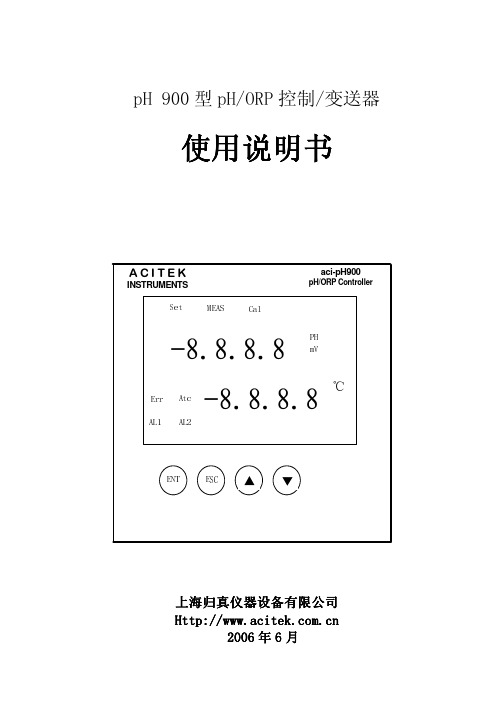
pH900使用说明
3
上海归真仪器设备有限公司
三、按键与显示器
8 位显示: 正常工作:上排 PH/ORP 显示(4 位),下排温度显示(4 位)。 精度校准:上排显示复合电极输入值,下排显示标准溶液的 PH 值提示符或 mV 值提示符。 参数目录:上排显示“SEt”,下排显示参数类提示符。 参数显示:上排显示参数值,下排显示参数名提示符。 10 只指示灯: PH: 灯亮表示仪器处于 PH 值测量状态; mV: 灯亮表示仪器处于 ORP 值测量状态;(PH 和 ORP 灯中只能有一只点亮); ℃: PH 值测量状态时,该灯亮;ORP 值测量状态时,该灯暗; MEAS:灯亮表示仪器处于 PH/ORP 值测量状态; Set:灯亮表示仪表处于参数设定状态(正常工作时该灯熄灭); CAl:灯亮表示仪表正处于 PH 或 ORP(由 PH 或 mV 灯决定)精度校准状态; Atc:灯亮表示仪表做 PH 测量时采用自动温度补偿;不亮表示采用手动设定温度补偿。 Err:灯亮表示 PH 复合电极校准出错(小于 30mV/PH 或大于 90mV/PH); AL1:灯亮表示继电器 1 闭合,即测量值达到报警 1 动作条件; AL2:灯亮表示继电器 2 闭合,即测量值达到报警 2 动作条件。
按“▲”或“▼”键可修改该参数值。
按“ENT”键存储该参数并显示下一个该类参数,或回到目录菜单。 按“ESC”键可直接返回到正常工作方式,但不存储被修改的参数。
七、参数分类
仪表参数共 7 类,见下表
序号 分类提示 参数名 提示符
内容
备注 有效范围 出厂值
01
LOCK LOC 进入菜单密码
0~255
0
02 SET
03
T
04
ATC AtC 自动温度补偿方式 1 / 0 ON/OFF
PMH900 使用说明书(4按键)

泛达温控器参数设置和操作
泛达温控器参数设置和操作使用
我们泛达温控器系列分为好几类,操作模式基本相似。
个别地方略有差别,总体来说只要能熟悉操作一个系列的温控器泛达所有系列都可以很灵活的操作和使用。
在这里把泛达仪表最成熟同时也是运用范围最广的P900X系列表来做一个典范说明。
泛达的温控表全都是智能数显PID调整功能,所以在使用时绝大多数参数都不需要再去设置。
常用的第一层参数里,按SET健会进入下一个参数。
AA的表默认的是输出是OUTL这个是100代表0-100%输出状态,AX的表OUTL是0,OUTH是100同样也是0-100%输出。
接下来就按SET健5秒进入第二层参数,PID的调整。
正常情况下,PID运算可以满足80%的工作环境下正常控制升温。
当然也有特殊环境下可能会存在冲温或是温度升不上去问题,这时只要在第一层参数下把自整定AT下面设为1按SET健保存这时有一个黄色AT指示灯闪烁表示已进入自动调整PID模式。
把SV值设置成正常控温的80%范围内打开加热系统正常升温,根据加热系统有时10分钟会结束有时会30分钟等AT黄色指示灯熄灭表示调整完成。
按SET+向左键同时按下,会进入第三层参数。
这里主要是对测量分度号和测量范围做一个设置,通常泛达仪表默认出厂的热电偶是k型0-400度。
如要改为s分度号可以在第一个参数INPUT下把光标健移下来,按向左健进行选择。
选好设置按SET健保存,再把USP 设为测量调整最高值。
这就是泛达温控器,定值表的操作使用方法。
欢迎广大客户朋友们体验证操作,多做些交流。
900-TC32数字温度控制器用户手册说明书
OFFOFF OFFOFFOFF48243535222229944.8DimensionsInstallationDimensions (mm)In the pack:*Digital Temperature Controller *Waterproof packing *Adapter*Instruction manualSolderless terminal size: M3.0* The terminal block can be removed for maintenance without disconnecting the terminal wiring.alarm. These are indicated by the letter "L" and "H". • The default is "2" (shaded)*2: Error shown only for "Process value / Set point". Not shown for other status.When an error has occurred, the No.1 display shows the error code. Take necessary measure according to the error code, referring the table bellow.If the input value exceeds the display limit (−1999 to 9999), though it is within the control range, [[[[ will be displayed under −1999 and ]]]] above 9999. Under these conditions, control output and alarm output will operate normally.Refer to “900-TC User's Manual” for details of control range.Turn the power OFF then back ON again. If the display remainsthe same, the controller must be repaired. If the display isrestored to normal, then a probable cause can be external noiseaffecting the control system. Check for external noise.After the correction of A/D converter error, turn the power OFF then back ON again. If the display remains the same, thecontroller must be repaired. If the display is restored to normal, then a probable cause can be external noise affecting the control system. Check for external noise.No.1 displayMeaning A/D convertererror *2Memory error Input error*2s.err (S. Err)e111 (E111)ActionAlarmControl outputStatus at errorOperates as above the upper limit.e333 (E333)Error display (troubleshooting)display mode and others in the advanced setting group.Refer to "900-TC32 User's Manual" for details.For communications details, please refer to "900-TC communications User's Manual".* AT in Adjustment groupDesignate "at2: 100% AT execute" or "at1: 40% AT execute" to execute AT and "off : AT cancel" to cancel AT.Also when AT execution ends, the display automatically returns to” off ” .AT (auto-tuning)Check the setting of the Input Type parameter, check the input wiring, and check for broken or shorts in the temperature sensor.*s.err will be displayed when a platinum resistance thermometer is mistakenly connected while Be sure to observe the following precautions to prevent operation failure, malfunction, oradverse affects on the performance and functions of the product. Not doing so may occasionally result in unexpected events. Use the product within specifications.(1) The product is designed for indoor use only. Do not use the product outdoors. Do not use orstore the product in any of the following locations.•Places directly subject to heat radiated from heating equipment. •Places subject to splashing liquid or oil atmosphere. •Places subject to direct sunlight.•Places subject to dust or corrosive gas (in particular, sulfide gas and ammonia gas). •Places subject to intense temperature change. •Places subject to icing and condensation. •Places subject to vibration and large shocks.(2) Use/store within the rated temperature and humidity ranges. Provide forced-cooling if required.(3) To allow heat to escape, do not block the area around the product. Do not block the ventilation holes on the product.(4) Be sure to wire properly with correct polarity of terminals.(5) Use the specified size (M3.0, width of 5.8 mm or less) of crimped terminals for wiring. Foropen-wired connections, use stranded or solid copper wires with rated temperature of over 70°C and a gauge of AWG24 to AWG18 (equal to a cross-sectional area of 0.205 to 0.8231 mm 2). The stripping length for screw terminal blocks is 6 to 8 mm. Up to two wires of some size and type, or two crimped terminals can be connected to a single terminal.(6) Do not wire the terminals which are not used.(7) Allow as much space as possible between the Temperature controller and devices thatgenerate a powerful high- frequency or surge.Separate the high-voltage or large-current power lines from other lines, and avoid parallel or common wiring with the power lines when you are wiring to the terminals.(8) Use this product within the rated load and power supply.(9) Make sure that the rated voltage is attained within two seconds of turning ON the powerusing a switch or relay contact. If the voltage is applied gradually, the power may not be reset or output malfunctions may occur.(10) Make sure that the T emperature Controller has 30 minutes or more to warm up after turning ON the power before starting actual control operations to ensure the correct temperature display. (11) When executing self-tuning, turn the load and the unit ON simultaneously, or turn the load ON before you turn the controller ON.(12) A switch or circuit breaker should be provided close to this unit. The switch or circuit breaker should be within easy reach of the operator, and must be marked as a disconnecting means for this unit.(13) Always turn OFF the power supply before removing the terminal block, and never touch nor apply shock to the terminals or electronic components.(14) Do not use paint thinner or similar chemical to clean with. Use standard grade alcohol. (15) Design system (control panel, etc) considering the 2 second of delay that the controller’s output to be set after power ON.(16) The output may turn OFF when shifting to certain groups. Take this into consideration when performing control.(17) The number of EEPROM write operations is limited. Therefore, use RAM write mode when frequently overwriting data during communications or other operations.(18) Do not use the Temperature Controller if the front sheet is peeling or torn.(19) When you remove the terminal block, check for corrosion.(20) When disassembling the Temperature Controller for disposal, use suitable tools.NOTICEPower supply voltage 100 to 240 VAC type24 V AC/DC type Operating frequency 50/60 HzOperating voltage range 85 to 110% of the rated voltage Power consumption Approx. 5.5 VA (100 to 240 VAC) Approx. 3 VA (24 VAC)Approx. 2 W (24 VDC)Indication accuracyThermocouple:(Ambient temperature: 23°C) (±0.3 % of indication value or ±1°C, whichever is greater) ±1 digit max. Platinum resistance thermometer: (±0.2 % of indication value or ±0.8°C, whichever is greater) ±1 digit max.Analog input: 0.2 % FS ±1 digit max.Event input Output current: approx. 7 mA per contact. Contact input ON:1 k Ω max., OFF: 100 k Ω min. No-contact input ON: residual voltage 1.5 V max.,OFF: leakage current 0.1 mA max.Control output 1 Relay outputs: 250 VAC, 2 A (resistive load) Electrical life of relay: 100,000 operations Triac model: 1 million operations Voltage output (for driving SSR): 12 VDC, 21 mACurrent output: 4 to 20 mA DC, 0 to 20mA DCLoad: 500 Ω max.Control method ON/OFF or 2-PID controlAuxiliary outputs Relay outputs: 250 VAC, 2 A (resistive load),electrical life: 100,000 operations Ambient temperature −10 to 55°C(with no icing or condensation)Ambient humidity 25 to 85%Storage temperature −25 to 65°C(with no icing or condensation)AltitudeMax. 2,000mRecommended fuse T2A, 250 VAC, time-lag,low-breaking capacityWeightApprox. 90 g (main unit only)Degree of protection Front panel: IP66Rear case: IP20, Terminal section: IP00Installation environment Installation category II, pollutiondegree 2 (as per IEC61010-1)Memory protection EEPROM (non-volatile memory)(Number of write operations: 1,000,000)Specifications• Since the voltage output (control output) is not electrically insulated from the internal wiring, one or other of the control output terminals must be left unearthed when using an earthed thermocouple thermometer. (Connection makes measurements unreliable due to sneak currents.)• To comply with EMC standards, the length of the cable connecting the universal TC/Pt input sensor must be 30 m or less. If the cable is longer than 30 m, the EMC standards will not be satisfied.Operation menuModels with Screw Terminal Blocks。
温控表设置
烘箱控制温控表设定:(霍尼韦尔DC1030CT )1、设定报警方式:當 LCK=0000 時,按住設定鍵(SET)及移位鍵秒,即可進入设定(若进入不了此菜单,先按照第3项的方式,检查参数锁LCK 的值是否为0000,如果不是,则需要修改为0000,方可进入此设定菜单)【检查是否为:K2,若不是,修改为K2】……【修改设置为:12(温差低温报警)】……【修改设置为:15((绝对值高温报警)】……按住設定鍵(SET)及移位鍵秒,即可返回主界面。
2、设定报警值:按下設定鍵(SET),即可进入参数值设定菜单【修改设置为:-6(表示低于(设定温度-6),AL1报警)】【修改设置为:0220(表示高于220度,AL2报警)】 返回主菜单按設定鍵(SET)循环一圈,即可返回主界面。
3、设定参数锁:按住設定鍵(SET) 3 秒不放,即可进入参数锁设定菜单……【修改设置为:0001(只允许修改设定值及进入报警值设定)】 按住設定鍵(SET) 3 秒不放,即可返回主界面。
3、按下移位鍵后释放,设定值(SV )会闪烁,按上(▲)、下(▼)键用(SET)确认。
4、初次设定完成,需要重新设定报警方式和报警值的时候,应当先按照第3项的方式将参数锁(LCK )设置为:0000,然后分别按照第1项和第2项的方法设定对应的参数和值。
设定完成后,依然将参数锁(LCK )设置为:0001。
※预裹刀温控表设定:(和泉MT700-2-1202)1、设定报警方式:同时按下設定鍵(SET)及移位鍵,即可進入密码区修改为0101……【修改设置为:12(温差低温报警)】……【修改设置为:15(绝对值高温报警)】 ……返回主菜单按設定鍵(SET)循环一圈,即可返回主界面。
2、设定报警值及参数锁:按住設定鍵(SET)3秒不放,即可进入参数值设定菜单【修改设置为:-3(表示低于(设定温度-3),AL1报警)】【修改设置为:0250(表示高于250度,AL2报警)】……【修改设置为:0001(只允许修改主控设定值及自整定)】返回主菜单按設定鍵(SET)循环一圈,即可返回主界面。
温度控制器怎样设置参数温度控制器设置参数方式
温度控制器怎样设置参数温度控制器设置参数方式温度控制器设置参数方式如下。
1、下限偏差告警设置:按SET键选择显示“SLP”,绿色显示屏显示该项参数的数值,选择移位、递增、递减键设置或修改该项参数。
该参数表示告警点低于主控设定点的相差值。
2、上限偏差告警设置:按SET键选择显示“SHP”,绿色显示屏显示该项参数的数值,选择移位、递增、递减键设置或修改该项参数。
该参数表示告警点高于主控设定点的相差值。
3、比例范围设置:按SET键选择显示“P”,绿色显示屏显示该项参数的数值,选择移位、递增、递减键设置或修改该项参数。
“P”值越大,温控器的主控继电器输出的灵敏度越低,“P”值越小,温控器的主控继电器输出的灵敏度越高。
4、积分时间设置:按SET键选择显示“I”,绿色显示屏显示该项参数的数值,选择移位、递增、递减键设置或修改该项参数。
设定的积分时间越短,积分作用越强。
5、微分时间设置:按SET键选择显示“D”,绿色显示屏显示该项参数的数值,选择移位、递增、递减键设置或修改该项参数。
仪表设定的微分时间越长,则以微分作用进行的修正越强。
6、比例周期设置:按SET键选择显示“T”,绿色显示屏显示该项参数的数值,选择移位、递增、递减键设置或修改该项参数。
7、自整定设置:按SET键选择显示“Aτ”,绿色显示屏显示该项参数的数值,选择移位、递增、递减键设置或修改该项参数;设置为“00”表示自整定关闭,设置为“01”表示自整定启动。
8、锁参数设置:按SET键选择显示“LOK”,绿色显示屏显示锁的状态,选择移位、递增、递减键设置或修改该项参数;设置为“00”表示不锁,设置为“01”表示只锁主控以外的参数,设置为“02”表示所有参数全锁定。
参数被锁定后,别人不能修改,需修改时要解锁,即设置为“00”。
9、主控温度上限设置:按SET键选择显示“SOH”,绿色显示屏显示该项参数的数值,选择移位、递增、递减键设置或修改该项参数;该参数表示主控继电器动作温度不能高于此值,否则,主控设定温度无效10、温度修正设置:按SET键选择显示“SC”,绿色显示屏显示该项参数的数值,选择移位、递增、递减键设置或修改该项参数;当温控器长时间运行后产生测量偏差时,就可使用该项功能修正误差。
- 1、下载文档前请自行甄别文档内容的完整性,平台不提供额外的编辑、内容补充、找答案等附加服务。
- 2、"仅部分预览"的文档,不可在线预览部分如存在完整性等问题,可反馈申请退款(可完整预览的文档不适用该条件!)。
- 3、如文档侵犯您的权益,请联系客服反馈,我们会尽快为您处理(人工客服工作时间:9:00-18:30)。
RKC HA900温控表主要参数设置方法
一.面板操作键:A/M(自动/手动)切换
R/L(远程/本地)切换
R/S(Run/Stop)运行/停止切换
二.按set键进行SV1、SV2温度设置:SV1→CH1(内热电偶),SV2→CH2(外热电偶)按住set键3秒以上:EV3绝对值报警温度,(目前对应的是EV3=1000度)CH1通道:PID参数人工设置炉口与炉尾处温控表的PID参数按出厂值,按实际控温情况定。
CH2:从开始升温进行自整定,切换进行本地控制,PID参数由自整定形成。
CH2自整定AT完成后,切换进行远程控制。
附CH1,表1(炉口处)CH1:P1:3 11:70 D1:15表2CH1:P1:2 11:240 D1:60表3CH1:P1:1 11:240 D1:60
表4CH1:P1:2 11:240 D1:60表5CH1:P1:5 11:240 D1:60 (炉尾处)
RKC厂商表自总定的PID参数:
表1(炉尾)CH1:P1:0.3 11:45 D1:12表2 CH1:P1:0.5 11:40 D1:10
表3(炉尾)CH1:P1:0.5 11:80 D1:20表4 CH1:P1:0.511:40 D1:10
表5(炉口)CH1:P1:0.4 11:44 D1:11
三:按住∠mode键3秒以上:A TU=ON (拉恒温区用)只CH2通道进行自整定。
A-M手动/自动切换r-L 本地/远程控制选择r-5:RUN/STOP切换
:
四.一边按set键一边按>mode键:
1、Pb:2.pb修正(拉恒温区用)Add1::通讯地址设置
Lck:密码设置bps1:19.2、b1T1:801、1nT1:5 PV数字滤波器:1dF=5 2dF=5
五.同时按set键和>mode键3秒以上(工程技术模式设置),必须在Stop状态下才能修改:F10:spch=0。
dE=6 (通道2的操作输出值MV)
dEuT=100条形分辨率) F11:Fn1=3 (输入1与输入2自动/手动的切换)
Fn2=1(远程/本地切换键操作)Fn3=1切换R/S
F21:1np=3(热电偶种类S型)UnIT=0(温度单位℃) PGdP=1(小数点以下1位)PGSL=0 (输入刻度下限值0)PGSH=1500(输入刻度上限值1500)
F22一样设置
F30:LoGC=5(输出逻辑) OUT4 :对应EV3 (5、6端子继电器输出)
ALC1=01111 RLC2=00011
F43:ES3=5 (EV3的最大报警值,外热电偶断偶超温报警)
EVA3=1 事件分配(输入1事件报警,内热电偶断偶超温报警OUT1)
F50:pd:0(热启动) CAM:2(输入2的用途) 级联控制 CAr=1(级联比率)CAb=000(通道CH2附加偏置)
F51:1:OS:1逆动作(加热控制)
F60:通讯协议:Cmps1:0(RKC通讯协议):cmps2:0。