ET-BLC-T顶装溢流防静电控制器说明书
A-T Controls, Inc. 77Series螺纹管道抗静电设备说明书

77Series-20191108Copyright 2013 A-T Controls, Inc.Triac 77 Series Ball Valves feature a high quality 316L investment casting. They are available with sanitary clamp or tube OD ends. Select the cavity filled or non-cavity filled design.Superior leak protection is accomplished by using a live-loaded packing system featuring Belleville washers and double “V” ring packing. An ISO 5211 mounting pad is provided for easy automation.Excellent for:• Pharmaceutical • Food and Beverage • Paint and Solvents • Viscous Fluids • ConfectionariesSERIES 77 Sanitary End 3-Piece DesignCincinnati, Ohio FAX (513) 247-5462********************PneumaticElectricSee automated data sheets for pre-sized assemblies# FOR 1/2”-3” - 4 PCS ; FOR 4” - 6 PCS& FOR 1/2”-2” - 4 PCS ; FOR 2-1/2”-3” - 8 PCS; FOR 4” - 12 PCS**FOR 1/2”-2” - ASTM A193 GRADE B8; FOR 2-1/2”-4” - ISO 3506-1 A2-70## FOR 1/2”-2” - ASTM A194 GRADE 8; FOR 2-1/2”-4” - ISO 3506-2 A2-70DIMENSIONS (IN)A-T Controls reserves the right to change product designs and technical/dimensional specifications without notice.9955 International Blvd.Cincinnati, Ohio PHONE (513) 247-5465FAX (513) 247-5462********************Tube O.D. according to ASME BPE 2019PRESSURE IN BAR77DA-20191108Copyright 2013 A-T Controls, Inc.SERIES 77 Sanitary EndsCincinnati, Ohio FAX (513) 247-5462********************Actuators are sized based on clean/clear fluid.SAMPLE PART #Valve SeriesEnd ConnectionSeat MaterialValve SizeTRIAC Actuator SeriesDouble Acting Solenoid Limit Switch See valve part number matrix for complete part number and options.Actuator Size 77-CF-150/2R3D-XXSERIES 77 Sanitary EndsDIMENSIONS SHOWN ARE FOR ASSEMBLIES SIZED FOR 80 PSI SUPPLY77SR-20191108Copyright 2013 A-T Controls, Inc.Cincinnati, Ohio FAX (513) 247-5462********************SeriesSee valve part number matrix for complete part number and options.Actuators are sized based on clean/clear fluid.SERIES 77Sanitary EndsDIMENSIONS SHOWN ARE FOR ASSEMBLIES SIZED FOR 80 PSI SUPPLYDIMENSIONS (IN) 77EL-20191108Copyright 2013 A-T Controls, Inc.Cincinnati, Ohio FAX (513) 247-5462********************Other options available - call for detailsActuators are sized based on clean/clear fluid.Manual and automated valve assemblies for gas burner management applicationsand safety shutoffVarious Seat MaterialsPTF E, RTF E, 50/50 STF E, 25% CTF E, Delrin,PEEK, UHMWPE, TFM-1600Operator OptionsQuarter-turn Gear OperatorsSpring Return “Deadman” HandlesOval handles, TEE HandlesSpecials and SolutionsSteam JacketsStem ExtensionsV-ported Control ValvesMulti-port Valve SolutionsFugitive Emissions Bonnets (TSM’s)Oxygen CleaningLockout BracketsVented Balls“No Play” Mounting Kits• FM ApprovedValves and AssembliesSpecial SeatsBalls and Seal DesignsFloor MountedDamper DrivesFusible LinkAssembliesLockoutMounting KitsSpecialMulti-Port ValvesSteam JacketedValvesLimit SwitchesMounted on Manual Valves180º ActuatorsStem ExtensionsDual ValveAssembliesCincinnati, Ohio 45246FAX (513) 247-5462********************。
天意顶驱培训手册

培训手册适用范围:初次使用天意顶驱的个人及单位盘锦辽河油田天意石油装备有限公司本手册包含与顶驱操作使用和维修有关的技术信息。
关于本产品的其他技术性说明分别包含在以下文件中:《服务手册》《机械液压与电气图册》《PRBA-01用户手册》《ACS800硬件手册》《ACS-BRK安装手册》《ACS800固件手册》《S7-300模板规范手册》《ET200M操作指导手册》《SITOP操作说明书》《SIEMENS制单元使用说明书》由于顶部驱动装置产品根据用户的使用工况和特殊要求而进行个性化设计,故针对本产品的技术文件可能不适用于同型号的其他产品,在使用技术文件时应当核对产品的型号与编号。
对于随机文件中没有涉及的内容,以及安装、使用和维护中的其它问题,如果需要,请与制造厂联系。
电话:************传真:************邮件:****************地址:盘锦经济开发区石油高新技术产业园邮政编码:124010目录目录 (IV)序言 (1)1、安全须知 (1)2、安全操作提示 (1)2.1.井控安全操作提示 (1)2.2.震击操作 (1)3、安装、调试与拆卸 (3)3.1.安装准备 (3)3.2.安装组织 (3)3.3.安装耳板支座和连接板 (3)3.4安放变频房 (4)3.5安装电缆架 (5)3.6将顶驱移至钻台面 (6)3.7顶驱与大钩连接 (7)3.8将顶驱与运输架分离 (8)3.9安装第一节导轨 (9)3.10分离运输架 (10)3.11安装第三节导轨 (11)3.12安装其余导轨 (12)3.13连接导轨和连接板 (13)3.14拆卸顶驱与导轨间连接销 (14)3.15安装导轨固定梁 (15)3.16连接泥浆管线 (16)4.顶驱拆卸 (17)司钻控制台 (18)5、司钻控制台面板 (18)5.1.钻井模式 (19)5.2.上扣模式 (20)5.3.卸扣模式 (21)5.4.其它操作 (22)6.特殊工况 (23)6.1.倒换大绳 (23)6.2.释放反扭矩 (23)6.3.下测井仪器 (24)6.4.使用震击器 (25)6.5.下套管和起套管 (25)6.5.1使用顶驱下套管有以下好处 (25)6.5.2使用顶驱下套管前的准备 (26)6.6.下套管 (26)6.7.起出套管 (28)6.8.起下钻 (29)7.顶驱上扣扭矩设定值标准 (29)序言1、安全须知顶部驱动装置的使用,应当由具有相应资格和经验的人员进行。
Eaton Logic Controller ELCB 控制器说明书

Eaton Logic ControllerELCB ControllersINSTRUCTION SHEET[Applicable Controllers]▪ELCB-PB10NNDR/T▪ELCB-PB14NNDR/T▪ELCB-PB20NNDR/T▪ELCB-PB30NNDR/T▪ELCB-PB40NNDR/TIL05001005EThank you for choosing this Eaton Logic Controller (ELC) series hascontrollers with 10 to 40 embedded I/O points. To ensure proper installation, operation and maintenance, please read this instruction sheet carefully before installing ELCB-PB.This instruction sheet provides only information on the electricalspecification, general functions, installation and wiring. It should be read and understood before attempting to install or use the unit. Further information can be found in the ELC series Programming Manual. These are OPEN TYPE controllers and therefore should be installed in an enclosure free of airborne dust, humidity, electric shock and vibration. Your application may require that the enclosure be locked to prevent non-maintenance staff from operating the controller (e.g. key or specific tools that are required for opening the enclosure) in cases where danger and damage to equipment or personnel may occur. DO NOT connect AC power to any of the DC I/O terminals; serious damage may occur. Check all wiring before switching on power. Ensure that the ground terminal is correctly grounded in order to prevent electromagnetic interference. This manual is subject to change without notice.Product ProfileDC sensor output(RS-232C)numbers(RS-485)Note1: The above figure is the layout of ELCB-PB20NNDR.DimensionUnit: mm Electrical Specifications#1: Please refer to “I/O Terminal Layout ” for the maximum number of in puts and outputson each controller. #2: UP , ZP must work with external auxiliary power supply 24VDC (-15% ~ +20%), ratedconsumption approx. 1mA/point. #3: See life curves (below)O p e r a t i o n (X 10)InstallationPlease install your controller in an enclosure with sufficient space around it to allow proper ventilation, as shown in the figure. DIN Rail Mounting: When mounting the ELCB to 35mm DIN rail, be sure to use the retaining clip to stop any side-to-side movement of the ELCB and reduce the chance of wires becoming loose. Theretaining clip is at the bottom of the ELCB.To secure your controller to the DIN rail, pull the clip down, place it onto the rail and gently push the clip up. To remove the ELCB, pull the retaining clip down with a flat screwdriver and gently remove the ELCB from DIN rail.Wiring1. Use 12-24 AWG single-core bare wire or multi-core (stranded) wire forthe I/O wiring. The ELCB terminal screws should be tightened to 3.80 kg-cm (3.30 in-lbs) using 60/75°C copper conductor only.2. DO NOT wire empty terminals. DO NOT place input signal wires andpower wires in the same wiring circuit.3. DO NOT drop tiny metallic conductors into the ELCB while installing thecontroller or other equipment.✹ Power SupplyThe input power supply for the ELCB-PB controller is AC. When operating ELCB-PB, please note the following points:1. The range of the input voltage should be 100 ~ 240VAC. The powersupply should be connected to L and N terminals. Please note: wiring 110VAC or 220VAC to a +24V output terminal or to digital inputs will result in serious damage to the ELCB.2. Use 1.6mm wire (or larger) for the grounding ELCB.3. A power loss for less than 10ms will not affect the operation of the ELCB.However, longer power loss or a sustained drop of power supply voltage will stop the running of the ELCB, and all outputs will turn “OFF”. When proper power is restored, the ELCB will resume operation. (Please keep this in mind when you use latched auxiliary relays and registers in your ELCB program.)4. Please refer to the electrical specification table for the maximum outputof the +24V power supply output terminal for each controller. DO NOT connect other external power supplies to this terminal. Every input point requires 5 to 7mA to drive when powered by rated voltage 24V to 30V(i.e. 16 input points will require 80 to 112mA to drive). The +24V input onELCB-PB is only for digital input points; other external loads are notsupported.✹ Safety WiringIn an ELCB control system, many devices are controlled at the same time, and actions of any device could influence another device, i.e. breakdown of any device may cause the breakdown of the entire control system. Therefore, we suggest you wire a protection circuit at the power supply input terminal. See the figure below.○1AC power supply:100 ~ 240VAC, 50/60Hz ○2Breaker○3Emergency stop: This button cuts off the system power supply when accidental emergency takes place.○4Power indicator ○5AC power supply load○6Power supply circuit protection fuse (2A) ○7ELCB (main processing unit)○8DC power supply output: 24VDC✹ I/O Point WiringThere are 2 types of DC inputs, SINK and SOURCE. (See the example below. For detailed wiring configuration, please refer to the specification of each controller.)DC Signal IN – SINK mode Input point loop equivalent circuit DC Signal IN – SOURCE mode Input point loop equivalent circuitRelay (R) output circuit wiring○1DC power supply ○2Emergency stop: Use an external switch ○3Fuse: Use 5 to 10A fuse at the shared terminal of output contacts to protect the output circuit○4Transient voltage suppressor: To extend the life span of relay contacts.1. Diode suppression of DC loads: Used for smaller loads.2. Diode + Zener suppression of DC load: Used with larger loads, and for rapidlyswitching applications.○5Incandescent light (resistive load) ○6AC power supply○7Mutually exclusive output: For example, Y4 and Y5 control the forward running and reverse running of the motor, forming an interlock for the external circuit, together with the ELCB internal program, to ensure safe operation in case of any unexpected errors.○8Neon indicator○9Suppressor: To reduce the interference on AC load (Figure 10)Transistor (T) output circuit wiring○1DC power supply ○2Emergency stop ○3Circuit protection fuse○4The output of the transistor module is “open collector”. If Y0/Y1 is set to pulse output, the output current has to be 0.05 ~ 0.5A to ensure normal operation of the output.Diode suppression: Used with smaller loads.1.2. Diode + Zener suppression: Used with larger loads, and for rapidly switchingapplications.RS-485 Wiring○1Master node ○2Slave node○3Terminal resistor ○4Shielded cableNote: 1. Terminal resistors are suggested to be connected to the master, and the last slave, with resistor value of 120 .2. To ensure communication quality, please wire using double shielded twistedpair cable (20AWG).3. When voltage drop occurs between the internal ground references of twosystems, connect the systems with Signal Ground point (SG) for achievingequal potential between systems so that a stable communication can beobtained.I/O terminal layoutELCB-PB10NNDR/TELCB-PB14NNDR/TELCB-PB20NNDRELCB-PB30NNDRD-D+SGX20X21D-D+SGX20X21ELCB-PB40NNDR/TD-D+SGC3Y14Y15Y17Y16X21X20X22X24X23X26X25X27D-D+SGY13Y14Y15Y17Y16X21X20X22X24X23X26X25X27。
CDL2ET1C系列电子级别控制器用户手册说明书

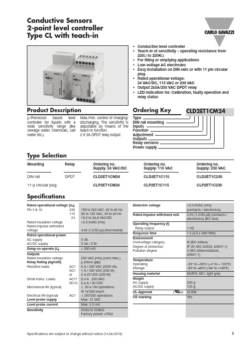
Mounting Relay Ordering no.Ordering no.Ordering no.Supply:24VAC/DC Supply:115VAC Supply:230VAC DIN-railDPDTCLD2ET1CM24CLD2ET1C115CLD2ET1C23011-p circular plugCLP2ET1CM24CLP2ET1C115CLP2ET1C230Conductive Sensors 2-point level controller Type CL with teach-in•Conductive level controller•Teach-in of sensitivity –operating resistance from 220Ωto 220K Ω•For filling or emptying applications •Low-voltage AC electrodes•Easy installation on DIN rails or with 11pin circular plug•Rated operational voltage:24VAC/DC,115VAC or 230VAC •Output 2x5A/250VAC DPDT relay•LED indication for:Calibration,faulty operation and relay statusProduct DescriptionMax./min.control of charging/discharging.The sensitivity is adjustable by means of the teach-in function.2X 5A DPDT relay output.µ-Processor based level controller for liquids with a wide sensitivity range (like sewage water,chemicals,salt water etc.).Type SelectionSpecificationsConnection cable2,3,or 4conductor PVC cable,normally screened.Cable length:max.100m.The resistance between the cores and the ground must be at least 220k.Normally,it is recommended to use a screened cable between probe and controller, e.g.where the cable is placed in parallel to the load cables (mains).The screen has to be connected to Y3(reference).DIP-switch settingSelect the needed function on the DIP-switches,so that the desirable application occurs.Press the push-button in front of the con-troller shortly,until the green LED flashes once.The DIP-switch setting will now be read by the controller.Teach-in:Make sure that the reference electrode and one of theother electrodes are in con-tact with the liquid –approximately 1cm.Press the “teach”pushbutton at the front of the controller for approximately 2seconds,until the green LED turns OFF .The controller will now auto-adjust itself according to the resistance of the measuring liquid.If the resistance of the liquid is outside the maximum range handled by the controller,the green LED will flash quickly for a period of 2seconds,indicating a wrong teach-in.Filter The signal delay is selectable from 1second or 3seconds,and works for the on/off switching of the output relays.Example 1The diagram shows the level control connected as max.Mode of OperationCLD2ET1CM24and min.control.The relays react to the low alternating current created when the electrodes are in contact with the liquid.The reference (Ref)must be connected to the container or if the container consists of a non-conductive material,to an additional electrode.(To be connected to pin Y3).(In the diagram this electrode is shown by the dotted line).Function:Charge or Discharge The Controller can be used as a minimum-maximum control for one system.ChargingDischargingTimeX-REFERENCE TERM PLUG Y16Y25Y37A12A2101111241432111228249DIP switches Discharge Charge Filter off Filter onDip Switch SettingsOperating ScheduleSituation Read DIP-switch settingTeach-inFailure indicationThe following schedule provides an overview of the setup and failure situationsCondition The DIP-switch setting has to match one of the descriptions written in ”mode of operation”Fill the tank with the liquid to be measured until thesecond longest electrode is immersed approx.1cmThe Green lamp isflashing fast for approx.2seconds after a teach-in operationAction Press the Teach-button in front of the controller shortly until the green controllamp turns off.Release the teach button immediatelyPress the Teach button in front of the controller for approx.2seconds until the green control lamp turn off continuously.Release the teach buttonControl the electrode for short-cut connections.Control that the resistance of the measured liquid is within the specified rangeGreen Control lampTeach button Green lampTeach button Green lampTeach button Green lampCLD2ET1CM24Wiring DiagramAccessories Delivery Contents•11pole corcular socket ZVD11•Mounting rack SM13•Amplifier •Packaging:Carton box •ManualCLD2ET1CM24 Dimension Drawings。
IMT埃柯特说明书_最新版本)

状态显示屏
ACT
天津埃柯特 A.C.T Control
开阀电源
关阀
向开启阀门方向运行。顺时针旋转操作旋钮,电动装
置向关阀方向运行。选择就地保持时,旋动操作旋钮
后松开,电动装置将向该方向持续运动,直至全行程。
选择就地点动时,旋动操作旋钮时,电动装置将向该
方向持续运动,若中途放开旋钮,电动装置将停止运 操作:功能按钮
步骤三:再次使用遥控器按下“停止”键。
2. “确认”操作
参数设定中,“确认”操作用于在菜 单选择页面确认所选选项,进入下一级 菜单;或者在参数设定页面“确认”当 前参数,回到上一级菜单的作用。
做法一:
ACT
就地保持 20%
100%
开阀 电源
关阀
ACT
参数查询 参数设定 语言选择钮转至“现
电动装置对选择旋钮有定位锁起保护功能,避免意外操作。建议使用标准挂锁。(见
本章第一张图)
6
第3章 电动装置显示界面说明
3.1 显示界面概览
接通电源后,电动装置液晶显示屏背光将点亮,同时电源指示灯将点亮。显示界面 包括一块128×64的图形点阵式液晶显示屏和三个LED灯组成。
其中,显示屏用于显示阀门的工作方式、状态、开度位置(用0~100%值表示)、故 障报警以及参数设定时参数的显示等。
关阀
作用;在数字设定方式时,起到“增加”本设定数字位数值
的作用。 5
做法一:
步骤一:将操作旋钮转至“关阀”位置;
步骤二:松开操作旋钮,让其自动回到“初始”位置。
做法二:在功能按钮处于“现场”情况下,使用遥控器按下“关”键。
5. “上移”/“循环右移”操作 在选项选择设定方式时,起到“上移”到下一个选项 的作用;在数字设定方式时,起到“循环右移”到下一位 数字的作用。 做法一: 步骤一:将操作旋钮转至“开阀”位置;
WJ(M-PRO)系列控制器使用说明书

防溢流防静电控制器 溢油静电保护器

3. ET-OP - T防溢 探杆 E T- O P - T防溢 探杆 利用 光学 原理 检 测 油 罐 车 舱 内 的 液
位状况。与鹤管捆绑式安装,连接到主控制器,向油库 防溢控制系统提供液位态信号,实现与付油系统的连锁 控制。 A. 光学原理,整体本安设计; B. 安装调节方便,通过锁紧定位装置,实现报警高度
第二步:根据液位高度,调节防溢探杆调节螺栓,设置好报警高度; 第三步:系统处于正常工作状态,可进行灌装作业; 第四 步: 当 检测 液面 达到 防溢 探杆 的 报 警 高 度 时 , 系 统 进 入 液 位 报 警 状 态,输 出 液 位 报 警信号。 第五步:灌装作业结束,收回防溢探杆,将静电接地夹夹于归位板,系统进入待机状 态,以备下次使用。
可调; C. 输入电压范围广,全数字电路设计,抗干扰能力强; D. 符合API标 准,5线制信 号; E. 标 配 电 缆 线长8米 。
第1页
ET-TLC 防溢流防静电控制器
4. ET-SC - T静电 接地 夹 A. 硬质合金顶尖; B. 破漆除锈,确保车体良好接地; C. 标配 螺旋 线长7.5米 。
系统框图
继电器
光电隔离
比较单元
静电接地夹
控制单元
声光报警
驱动放大
信号整形
防溢探杆
归位板 2.2 系统组成及功能
E T-TL C顶装 防 溢流 防静 电控 制器 主 要 由 主 控 制 器 、ET - A L声 光 报 警 器 、ET- O P - T防 溢 探 杆 、E T -SC静 电接 地夹 、E T - RP归 位板 、 接 地 线 及 接 线 盒 组 成 。
ETI GF Pro自动雪和冰凌卸液控制器说明书

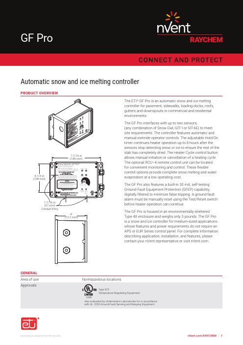
/RAYCHEM | 1RAYCHEM-DS-H58849-ETIGFPRO-EN-2302Automatic snow and ice melting controllerThe ETI ® GF Pro is an automatic snow and ice melting controller for pavement, sidewalks, loading docks, roofs, gutters and downspouts in commercial and residential environments.The GF Pro interfaces with up to two sensors,(any combination of Snow Owl, GIT-1 or SIT-6E) to meet site requirements. The controller features automatic and manual-override operator controls. The adjustable Hold-On timer continues heater operation up to 8 hours after the sensors stop detecting snow or ice to ensure the rest of the slab has completely dried. The Heater Cycle control button allows manual initiation or cancellation of a heating cycle. The optional RCU–4 remote control unit can be located for convenient monitoring and control. These flexiblecontrol options provide complete snow melting and water evaporation at a low operating cost.The GF Pro also features a built-in 30 mA, self-testing Ground-Fault Equipment Protection (GFEP) capability, digitally filtered to minimize false tripping. A ground-fault alarm must be manually reset using the Test/Reset switch before heater operation can continue.The GF Pro is housed in an environmentally-sheltered Type 4X enclosure and weighs only 3 pounds. The GF Pro is a snow and ice controller for medium-sized applications whose features and power requirements do not require an APS or EUR Series control panel. For complete information describing application, installation, and features, please contact your nVent representative or visit .PRODUCT OVERVIEWConduit EntryGENERAL/RAYCHEM | 2©2023 nVent. All nVent marks and logos are owned or licensed by nVent Services GmbH or its affiliates. All other trademarks are the property of their respective owners. nVent reserves the right to change specifications without notice. RAYCHEM-DS-H58849-ETIGFPRO-EN-2302Our powerful portfolio of brands:North AmericaTel +1.800.545.6258Fax +1.800.527.5703**********************ENCLOSURE Protection Type 4XDimensions 5 1/2" (L) x 8 1/8" (W) x 4 3/8" (H)140 mm (L) x 207 mm (W) x 112 mm (H)MaterialPolycarbonateCover attachment Polycarbonate cover, machine screws Weight 3 pounds (not including sensors)Mounting Wall mountEntries2 x 3/4" entries (right) for NEC Class 2 connections3 x 1-1/16" entries (bottom and left) for supply and load powerCONTROL Supply voltage 100-277 Vac; 50/60 Hz Load30 A maximum resistiveHeater Hold-On timer 0 – 8 hrs; actuated by snow stopping or toggle switchSystem testSwitch toggles heater contact on and off. If temperature exceeds optional high limit thermistor (45°F), heater shuts off to reduce costs and prevent damageFRONT PANEL INTERFACE Status indicatorsSUPPLY (green): Power onHEAT (yellow): Heating cycle in progress SNOW (yellow): Sensor(s) detect snow GFEP (red): Ground-Fault condition GFEP (red, flashing): FailedGFEP (red, rapid flashing): GFEP test in progressGROUND-FAULT EQUIPMENT PROTECTION (GFEP)Set point30 mAAutomatic self-test GFEP verified before contactors operate; GFEP runs on start-up and every 24 hours Manual Test/Reset Test/Reset switch on front panelENVIRONMENTAL Operating temperature –31°F to 130°F (–35°C to 55°C)Storage temperature –67°F to 167°F (–55°C to 75°C)ORDERING INFORMATION* The GF Pro does not come with any sensors. Sensors must be ordered separately.。
- 1、下载文档前请自行甄别文档内容的完整性,平台不提供额外的编辑、内容补充、找答案等附加服务。
- 2、"仅部分预览"的文档,不可在线预览部分如存在完整性等问题,可反馈申请退款(可完整预览的文档不适用该条件!)。
- 3、如文档侵犯您的权益,请联系客服反馈,我们会尽快为您处理(人工客服工作时间:9:00-18:30)。
3. 液位报警 当检测液位达到防溢探杆的报警位置时,系统处于液位报警状态,防溢指示灯显示红 色,静电指示灯显示绿色,蜂鸣器响,防溢信号输出报警信号,静电信号输出正常信号。
4. 静电接地报警 当静电接地夹没有夹好或接地回路超过规定阻值时,系统处于静电接地报警状态,防溢 指示灯显示绿灯,静电指示灯显示红灯,蜂鸣器响,静电信号输出报警信号,防溢信号输出 正常信号。
3
5.3 机械安装
3
6 .系 统 使 用
3
6.1 工作状态指示
3
6.2 操作步骤
4
7 .产 品 安 装 使 用 注 意 事 项
4
8 .常 见 故 障 及 应 急 措 施
4
附录一 电路板标示示意图
5
附录二 电气连接示意图
6
附录三 现场安装示意图
7
附录四 现场安装布线示意图
8
附录五 主控制器安装尺寸图
9
附录六 归位板安装尺寸图
10
青岛艾特仪器有限公司
QINGDAO EVERBRIGHT INSTRUMENT CO.,LTD.
1 系统简介
ET-B L C - T顶装 防溢 流防 静电 控制 器 专 为 顶 部 付 油 系 统 设 计 , 有 效 防 止 液 体 溢 出 和 保 证 静电接地电阻符合相关安全标准的规定,组成石油化工产品储运过程中的防溢流防静电系 统。
系统框图
继电器
光电隔离
比较单元
静电接地夹
控制单元
声光报警
驱动放大
信号整形
防溢探杆
归位板 2.2 系统组成及功能
E T-BL C - T顶装 防溢 流防 静电 控制 器 主 要 由 主 控 制 器 、E T - A L声 光 报 警 器 、E T - O P-T防 溢 探 杆、ET- S C静电 接地 夹、ET-R P归位 板、 接 地线 及接 线盒 组成 。
5. 归位板 检测静电接地夹使用后是否归位。
6. 接地线 确保系统外壳、静电接地夹等接地。
7. 二通接线盒、三通接线盒 二通接线盒延长防溢探杆电缆连接到主控制器,三
通接线盒连接归位板、静电接地夹到主控制器。
3 产品特点
1. 系统应用数字电路设计,性能稳定,抗干扰能力强; 2. 防溢探杆采用光学原理,整体环氧树脂密封,防腐、防水; 3. 防溢探杆故障具有自检功能,更安全; 4. 提供声光报警信号,及时了解系统工作状态; 5 . 开 关量 信号 输出, 接口 容量5 A,3 0 VDC或5A,2 5 0 V AC。
5. 液位、静电接地报警 当静电接地和液位同时报警时,防溢指示灯和静电指示灯均显示红色,蜂鸣器响,防溢 信号和静电信号均输出报警信号。
6. 防溢探杆故障报警 当防溢探杆接线出现短路、断路现象或防溢探杆故障时,系统处于故障报警状态,防溢 指示灯显示黄色,静电指示灯显示绿色,蜂鸣器响,防溢信号输出报警信号,静电信号输出 正常信号。
间。 C . 9号 端子 为接 地端 ,与 控制 器外 壳 连 接 , 确 保 可 靠 接 地 。 D . 10~1 3号 端子 接声 光报 警器 ,采 用>4×0.5m m²电 缆 线 , 外 径 介 于 Φ8 m m~Φ12mm之
间。
第2页
青岛艾特仪器有限公司
QINGDAO EVERBRIGHT INSTRUMENT CO.,LTD.
8 常见故障及应急措施
1. 系 统 出现 故障时 ,请参照 “6.1工 作 状 态 指 示”检 查 , 确 定 故 障 原 因 。
2. 防溢探杆故障报警的可能原因是线路接触不良、短路、断路或传感器故障造成的。
5.1.2 电气连接图 见附 录二 E T-BLC - T顶装 防溢 流防 静电 控制 器 电气 连接 示意 图。
5.2 现场布线示意图
见附 录三 :ET - BLC-T顶 装防 溢流 防 静 电 控 制 器 现 场 安 装 示 意 图 。 5.3 机械安装
见附 录四 :ET - BLC-T顶 装防 溢流 防 静 电 控 制 器 现 场 安 装 布 线 示 意 图 。 见附录五:主控制器安装尺寸图。 见附 录六 :E T - RP归 位板 安装 尺 寸图 。
2. ET-AL声 光报 警器 A. 提供液位、静电的光报警指示灯; B. 提 供蜂 鸣器 声音 报警, > 9 0 dB(30c m直 线 距 离)。
3. ET-OP - T防溢 探杆 E T- O P - T防溢 探杆 利用 光学 原理 检 测 油 罐 车 舱 内 的 液
位状况。与鹤管捆绑式安装,连接到主控制器,向油库 防溢控制系统提供液位态信号,实现与付油系统的连锁 控制。 A. 光学原理,整体本安设计; B. 安装调节方便,通过锁紧定位装置,实现报警高度
第二步:根据液位高度,调节防溢探杆调节螺栓,设置好报警高度; 第三步:系统处于正常工作状态,可进行灌装作业; 第四 步: 当 检测 液面 达到 防溢 探杆 的 报 警 高 度 时 , 系 统 进 入 液 位 报 警 状 态,输 出 液 位 报 警信号。 第五步:灌装作业结束,收回防溢探杆,将静电接地夹夹于归位板,系统进入待机状 态,以备下次使用。
2 系统工作原理及组成
2.1 工作原理
E T-BLC - T顶装 防溢 流防 静电控 制 器 专 为 顶 部 付 油 系 统 设 计 的 防 溢 、 检 测 静 电 接 地 的 自 动 控 制系 统。 系统 通过E T - O P-T防 溢探 杆 检 测 液 位 信 号 和 静 电 接 地 夹 检 测 接 地 信 号 , 当 液 位超过报警位置或接地回路电阻超过规定阻值时,系统输出声光报警信号供现场工作人员 及时了解系统工作状态,同时输出继电器开关信号供付油系统控制。
6 系统使用
6.1 工作状态指示
Байду номын сангаас防溢指示灯
静电指示灯
EX
蜂鸣器
液位
静电
1. 待机状态 当静电接地夹归位,夹在归位板上时,系统处于待机状态,防溢指示灯和静电指示灯均 显示黄色,蜂鸣器不响,系统不检测信号,防溢信号和静电信号均输出报警信号。
2. 正常工作状态 当静电接地夹摘离归位板,夹在车体上并且接地良好,同时检测的液面没有达到报警位 置时,系统处于正常工作状态,防溢指示灯和静电指示灯均显示绿色,蜂鸣器不响,防溢信 号和静电信号均输出正常信号。
可调; C. 输入电压范围广,全数字电路设计,抗干扰能力强; D. 符合API标 准,5线制信 号; E. 标 配 电 缆 线长8米 。
第1页
ET-BLC-T 防溢流防静电控制器
4. ET-SC - T静电 接地 夹 A. 硬质合金顶尖; B. 破漆除锈,确保车体良好接地; C. 标配 螺旋 线长7.5米 。
顶装防溢流防静电控制器 (ET-BLC-T)
说明书
目录
1 .系 统 简 介
1
2 .系 统 工 作 原 理 及 组 成
1
2.1 工作原理
1
2.2 系统功能及组成
1
3 . 产品特点
2
4 .系 统 参 数
2
5 .系 统 安 装
2
5.1 电气安装
2
5.1.1 电路板标示
2
5.1.2 电气连接图
3
5.2 现场布线示意图
第3页
ET-BLC-T 防溢流防静电控制器
7. 防溢探杆故障报警、静电接地报警 当防溢探杆故障报警和静电接地报警同时出现时,防溢指示灯显示黄色,静电指示灯显 示红色,蜂鸣器响,防溢信号和静电信号均输出报警信号。
6.2 操作步骤
第一 步: 当系 统处 于待 机状 态时 ,将 静 电 接 地 夹 拿 离 归 位 板 , 静 电 接 地 报 警 ,当静 电 接 地夹夹于车体且接地良好时,静电接地正常。
1. 主控制器 A . 检 测E T - O P - T防 溢 探 杆 液 位 信 号 和E T - S C - T静 电 接 地 夹
的信号; B. 向E T-AL声光报 警器 提供 声光 报 警 信 号 ; C. 向付油系统输出开关量信号; D. 防 爆 标志 :Exd[ia ] I I B T4。
接口 容量5A,30 V D C或5A,250V A C 1 0 . 本 安输 出参 数:
Uo=16.5V Io=874mA Po=3.6W Co=1.8uF Lo=0.09mH
5 系统安装
5.1 电气安装
5.1.1 电路板标示 见附录一 ET-BLC-T 防溢流防静电控制器电路板标示示意图。 1. 技术要求 A. 1~6号端子为继电器信号输出,注意常开常闭选择。 B . 7~8号 端子 为2 4VD C电 源输 入端 , 采 用> 2×1mm² 电 缆 线 , 外 径 介 于 Φ8mm~Φ1 2 mm之
E T-B L C - T顶装 防溢 流防 静电 控制 器 经 国 家 级 仪 器 仪 表 防 爆 安 全 监 督 检 验 站( NEPS I )检 验,符合下列标准:
GB38 3 6 . 1-2000“ 爆炸 性气 体环 境用 电气 设备 第1部 分: 通用 要求 ” GB38 3 6 . 2-2000“ 爆炸 性气 体环 境用 电气 设备 第2部 分: 隔爆 型“d” ” GB38 3 6 . 4-2000“ 爆炸 性气 体环 境用 电气 设备 第4部 分: 本质 安全 型“i” ” 产 品 防爆 标志 为E x d[ia] I I B T 4, 防 爆 合 格 证 号 为G Y B 0 91773X。
4 系统参数
1 . 工 作电 压:220V A C±1 0% 2 . 工 作电 流:<20m A 3 . 工 作温 度:-40℃~6 0℃ 4 . 响 应时 间:<1s 5 . 检 测电 阻:<55Ω 6. 防 护等 级:IP65 7 . 防 爆等 级:Exd[ i a ] IIBT4 8. 报警方式:声光报警 9. 输出信号:继电器输出,常开常闭可选
