拖链电缆选型手册
电缆选型手册及常用公式

电缆的选型与配线选择电线平方数和电流一般铜线平安电流最大为:平方毫米铜电源线的平安载流量--。
平方毫米铜电源线的平安载流量--。
平方毫米铜电源线的平安载流量--。
平方毫米铜电源线的平安载流量--。
平方毫米铜电源线的平安载流量--。
平方毫米铜电源线的平安载流量--。
如果是铝线截面积要取铜线的倍。
如果铜线电流小于,按每平方毫米来取肯定平安。
如果铜线电流大于,按每平方毫米来取。
导线的截面积所能正常通过的电流可根据其所需要导通的电流总数进行选择,一般可按照如下顺口溜进行确定:十下五,百上二, 二五三五四三倍,七零九五两倍半,铜线升级算.就是平方以下的铝线,平方毫米数乘以就可以了,要是铜线呢,就升一个档, 比方平方的铜线,就按铝线平方计算.一百以上的都是截面积乘以, 二十五平方以下的乘以, 三十五平方以上的乘以, 和平方都乘以,这么几句口诀应该很好记吧,说明:只能作为估算,不是很准确。
另外如果按室内记住电线平方毫米以下的铜线,每平方电流不超过就是平安的,从这个角度讲,你可以选择平方的铜线或平方的铝线。
米内,导线电流密度平方毫米比拟适宜,米,平方毫米米,平方毫米,米以上要小于平方毫米。
从这个角度,如果不是很远的情况下,你可以选择平方铜线或者平方铝线。
如果真是距离米供电〔不说是不是高楼〕,一定采用平方的铜线。
导线的阻抗与其长度成正比,与其线径成反比。
请在使用电源时,特别注意输入与输出导线的线材与线径问题。
以防止电流过大使导线过热而造成事故。
导线线径一般按如下公式计算:铜线:*`铝线:*`式中:——导线中通过的最大电流〔〕——导线的长度〔〕`——充许的电压降〔〕——导线的截面积〔〕说明:、`电压降可由整个系统中所用的设备范围内,分给系统供电用的电源电压额定值综合起来考虑选用。
、计算出来的截面积往上靠. 绝缘导线载流量估算铝芯绝缘导线载流量与截面的倍数关系导线截面( )载流是截面倍数载流量()估算口诀:二点五下乘以九,往上减一顺号走。
电缆选型手册及常用公式

电缆的选型与配线选择电线平方数和电流一般铜线安全电流最大为:平方毫米铜电源线的安全载流量--28A。
4 平方毫米铜电源线的安全载流量--35A 。
6 平方毫米铜电源线的安全载流量--48A 。
10 平方毫米铜电源线的安全载流量--65A。
16 平方毫米铜电源线的安全载流量--91A 。
25 平方毫米铜电源线的安全载流量--120A。
如果是铝线截面积要取铜线的倍。
如果铜线电流小于 28A,按每平方毫米 10A 来取肯定安全。
如果铜线电流大于 120A,按每平方毫米 5A 来取。
导线的截面积所能正常通过的电流可根据其所需要导通的电流总数进行选择,一般可按照如下顺口溜进行确定:十下五,百上二, 二五三五四三倍,七零九五两倍半,铜线升级算.就是 10 平方以下的铝线,平方毫米数乘以 5 就可以了,要是铜线呢,就升一个档, 比如平方的铜线,就按铝线 4 平方计算.一百以上的都是截面积乘以 2, 二十五平方以下的乘以 4, 三十五平方以上的乘以3, 70 和 95 平方都乘以 ,这么几句口诀应该很好记吧,说明:只能作为估算,不是很准确。
另外如果按室内记住电线 6 平方毫米以下的铜线,每平方电流不超过 10A 就是安全的,从这个角度讲,你可以选择平方的铜线或平方的铝线。
10 米内,导线电流密度 6A/平方毫米比较合适,10-50 米,3A/平方毫米,50-200 米,2A/平方毫米,500 米以上要小于 1A/平方毫米。
从这个角度,如果不是很远的情况下,你可以选择 4 平方铜线或者 6 平方铝线。
如果真是距离 150 米供电(不说是不是高楼),一定采用 4 平方的铜线。
导线的阻抗与其长度成正比,与其线径成反比。
请在使用电源时,特别注意输入与输出导线的线材与线径问题。
以防止电流过大使导线过热而造成事故。
导线线径一般按如下公式计算:铜线: S= IL / *U`铝线: S= IL / 34*U`式中:I——导线中通过的最大电流(A)L——导线的长度(M)U`——充许的电压降(V)S——导线的截面积(MM2)说明: 1、U`电压降可由整个系统中所用的设备范围内,分给系统供电用的电源电压额定值综合起来考虑选用。
电缆选型手册簿及常用公式

电缆的选型与配线选择电线平方数和电流一般铜线安全电流最大为:2.5 平方毫米铜电源线的安全载流量--28A。
4 平方毫米铜电源线的安全载流量--35A 。
6 平方毫米铜电源线的安全载流量--48A 。
10 平方毫米铜电源线的安全载流量--65A。
16 平方毫米铜电源线的安全载流量--91A 。
25 平方毫米铜电源线的安全载流量--120A。
如果是铝线截面积要取铜线的 1.5-2 倍。
如果铜线电流小于 28A,按每平方毫米 10A 来取肯定安全。
如果铜线电流大于 120A,按每平方毫米 5A 来取。
导线的截面积所能正常通过的电流可根据其所需要导通的电流总数进行选择,一般可按照如下顺口溜进行确定:十下五,百上二, 二五三五四三倍,七零九五两倍半,铜线升级算.就是 10 平方以下的铝线,平方毫米数乘以 5 就可以了,要是铜线呢,就升一个档, 比如 2.5 平方的铜线,就按铝线 4 平方计算.一百以上的都是截面积乘以 2, 二十五平方以下的乘以 4, 三十五平方以上的乘以 3, 70 和 95 平方都乘以 2.5,这么几句口诀应该很好记吧,说明:只能作为估算,不是很准确。
另外如果按室内记住电线 6 平方毫米以下的铜线,每平方电流不超过 10A 就是安全的,从这个角度讲,你可以选择 1.5 平方的铜线或 2.5 平方的铝线。
10 米内,导线电流密度 6A/平方毫米比较合适,10-50 米,3A/平方毫米,50-200 米,2A/平方毫米,500 米以上要小于 1A/平方毫米。
从这个角度,如果不是很远的情况下,你可以选择 4 平方铜线或者 6 平方铝线。
如果真是距离 150 米供电(不说是不是高楼),一定采用 4 平方的铜线。
导线的阻抗与其长度成正比,与其线径成反比。
请在使用电源时,特别注意输入与输出导线的线材与线径问题。
以防止电流过大使导线过热而造成事故。
导线线径一般按如下公式计算:铜线: S= IL / 54.4*U`铝线: S= IL / 34*U`式中:I——导线中通过的最大电流(A)L——导线的长度(M)U`——充许的电压降(V)S——导线的截面积(MM2)说明: 1、U`电压降可由整个系统中所用的设备范围内,分给系统供电用的电源电压额定值综合起来考虑选用。
KabelSchlep(佳宝莱)电缆拖链选型
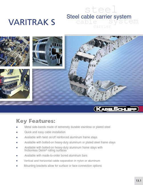
13.1• Metal side-bands made of extremely durable stainless or plated steel • Quick and easy cable installation• Available with twist on/off reinforced aluminum frame stays•Available with bolted-on heavy-duty aluminum or plated steel frame stays• Available with bolted-on heavy-duty aluminum frame stays with frictionless Delrin ® rolling surfaces • Available with made-to-order bored aluminum bars• Vertical and horizontal cable separation in nylon or aluminum •Mounting brackets allow for surface or face connection optionsVARITRAK SsteelcarriercablesystemSteel cable carrier system13V A R I T R A K S13.2Speci fi cations are subject to change without notice.KS-1106-GC-ASelf-Supporting Lengthssystems, KS Support Rollers or major credit cards acceptedA product group’s EVA score is a general indicator that allows a customer to quickly and easilyFor more information onextended travel systems, see pages 2.27-2.36Number of Systems Req.8x x +-+++-+++-xx Type & Position Brackets M A I /F A I # of Links Length 32 Links T ype Frame Stay RS2Dividers(#vert / #horz)5v/0hBend Radius 135Carrier TypeS0650.1Cavity Width 10.00”(B i )VARITRAK S steel• open style • customizable widthsNeed help?1-800-443-4216or 13VARITRAKS 13.3Specifi cations are subject to change without notice. KS-1106-GC-ASeries S 0650.1 Features one twist in/out aluminum bar on the outer radius and one bolted-on aluminum bar on the inner radius per frame stay.Usable Cavity Widths (B i)are available from2.00” (50.8 mm)through 12.00” (304.8 mm).Ten standard width sizes are available from stock. Custom widths are also available in any width increment required by the customer.RS1 Bar Systemdividers can be slid into position13V A R I T R A K S13.4Speci fi cations are subject to change without notice.KS-1106-GC-AFeatures bolted on aluminum bars on both the outer radius and the inner radius per frame able Cavity Widths (B i ) are available from 2.00” (51 mm) through 12.00” (304.8 mm).Ten standard width sizes are available from stock. Custom widths are also available in any width increment required by the customer.RS2Bar SystemMounting Bracket OptionsFor detailed drawings anddimensions of available options, please see pages: 13.32 - 13.33dividers can be slid into position0.12(3)=s TStandard RS2STYLE Vertical Divider=B i + 0.63 (16)=B i + 1.22 (31)h iRecommendedMAXIMUMWidthRecommendedMINIMUMWidthh G h G Note: For extended widths, multiple chain-band designs factory:1-800-443-42160.51(13)PN:44250S0650.1 - 2.00” - RS2 - (KR) - (# of links) - (brackets) - (dividers)S0650.1 - 12.00” - RS2 - (KR) - (# of links) - (brackets) - (dividers)bars on outside radiusB st = Cut bar length B k = Outer chain width B i = I nner chain cavity(usable) width h G = Outer chain link height h i = I nner chain cavity(usable) height S T = Vertical divider thicknessVARITRAK Ssteel • open style • customizable widthsNeed help? 1-800-443-4216 or 13V A R I T R A K S13.5Speci fi cations are subject to change without notice.KS-1106-GC-ASeriesS 0650.1Features bolted-on heavy-duty split and bored aluminum bars.Bar Widths (B st ) are available from 2.50” (63.5 mm) through 19.00” (482.6 mm) in any width increment required by the customer.LGBar System• B y simply unscrewing 1 bolt per split-bar at bothends of each bar and sliding out the unbolted split-bar, cables & hoses can be easily installed (laid inside, in each speci fi cally designed 1/2 round).• I deal when unique cables and hoses must beindividually separated.Why use LG system13V A R I T R A K S13.6Speci fi cations are subject to change without notice.KS-1106-GC-AWhen application travel exceeds major credit cards acceptedDDEDA product group’s EVA score is a general indicator For more information onextended travel systems,see pages 2.27-2.36Number of Systems Req.4x x +-+++-+++-xx Type & Position Brackets M A I /F A I # of Links Length 35 Links T ype Frame Stay RMR Dividers(#vert / #horz)9v/0hBend Radius 170Carrier TypeS0950Cavity Width 18.00”(B i )VARITRAK Ssteel • open style • customizable widthsNeed help? 1-800-443-4216 or 13V A R I T R A K S13.7Speci fi cations are subject to change without notice.KS-1106-GC-ASeriesS 0950Features one twist in/out aluminum bar on the outer radius and one bolted-on aluminum bar on the inner radius per frame stay.Usable Cavity Widths (B i ) are available from 3.00” (76.2 mm) through 11.00” (279.4 mm).Ten standard width sizes are available from stock. Custom widths are also available in any width increment required by the customer.RS1Bar Systemh G =B i + 0.94 (24)=B i + 1.69 (43)dividers can be slid into position0.16(4)=s TStandard RS1STYLE Vertical Dividerh iRecommendedMINIMUMWidth0.55(14)PN: 42160S0950 - 3.00” - RS1 - (KR) - (# of links) - (brackets) - (dividers)B st = Cut bar lengthB k = Outer chain width B i = I nner chain cavity(usable) width h G = Outer chain link height h i = I nner chain cavity(usable) height S T = Vertical divider thickness13V A R I T R A K S13.8Speci fi cations are subject to change without notice.KS-1106-GC-AMounting Bracket OptionsFor detailed drawings anddimensions of available options, please see pages: 13.32 - 13.33dividers can be slid into position0.16(4)=s TStandard RS2STYLE Vertical DividerB st B k =B i + 0.71 (18) =B i + 1.46 (37)h iRecommendedMAXIMUMWidthRecommendedMINIMUMWidthh G h G Note: For extended widths, multiple chain-band designs factory:1-800-443-42160.55(14)PN: 42160S0950 - 3.00” - RS2 - (KR) - (# of links) - (brackets) - (dividers)S0950 - 14.00” - RS2 - (KR) - (# of links) - (brackets) - (dividers)bars on outside radiusB st = Cut bar lengthB k = Outer chain width B i = I nner chain cavity(usable) width h G = Outer chain link height h i = I nner chain cavity(usable) height S T = Vertical divider thicknessFeatures bolted on aluminum bars on both the outer radius and the inner radius per frame able Cavity Widths (B i ) are available from 3.00” (76.2 mm) through 14.00” (355.6 mm).Ten standard width sizes are available from stock. Custom widths are also available in any width increment required by the customer.RS2Bar SystemVARITRAK Ssteel • open style • customizable widthsNeed help? 1-800-443-4216 or 13V A R I T R A K S13.9Speci fi cations are subject to change without notice.KS-1106-GC-ASeriesS 0950Features heavy-duty double bolted-on aluminum bar on the outer radius and on the inner radius per frame stay.Usable Cavity Widths (B i ) are available from 3.00” (76.2 mm) through 23.00” (584.2 mm) in any width increment required by the customer.RMSBar Systemdividers can be slid into position0.16(4)=s TStandard RMS STYLE Vertical DividerRecommendedMAXIMUMWidthRecommendedMINIMUMWidthNote:factory:1-800-443-4216h G st k =B i + 0.71 (18) =B i + 1.46 (37)h ih G 0.57(14.5)PN: 42130S0950 - 3.00” - RMS - (KR) - (# of links) - (brackets) - (dividers)S0950 - 23.00” - RMS - (KR) - (# of links) - (brackets) - (dividers)bars on outside radiusB st = Cut bar lengthB k = Outer chain width B i = I nner chain cavity(usable) width h G = Outer chain link height h i = I nner chain cavity(usable) height S T = Vertical divider thickness13V A R I T R A K S13.10Speci fi cations are subject to change without notice.KS-1106-GC-AFeatures heavy-duty double bolted-on aluminum bar with integrated roller system on the outer radius and on the inner radius per frame stay.Usable Cavity Widths (B i ) are available from 3.00” (76.2 mm) through 22.00” (558.8 mm) in any width increment required.RMRBar SystemVARITRAK Ssteel • open style • customizable widthsNeed help? 1-800-443-4216 or 13V A R I T R A K S13.11Speci fi cations are subject to change without notice.KS-1106-GC-ASeriesS 0950Features bolted-on heavy-duty split and bored aluminum barsBar Widths (B st ) are available from 3.00” (76.2 mm) through 23.00” (584.2 mm) in any width increment required by the customer.LGBar SystemMounting Bracket OptionsFor detailed drawings anddimensions of available options, please see pages: 13.32 - 13.3313V A R I T R A K S13.12Speci fi cations are subject to change without notice.KS-1106-GC-Amajor credit cards acceptedsystems, KS Support Rollers orDDEDA product group’s EVA score is a general indicator that allows a customer to quickly and easilyFor more information on extended travel systems,see pages 2.27-2.36Number of Systems Req.10x x +-+++-+++-xx Type & Position Brackets M F/F F # of Links Length 27 Links T ype Frame Stay RS1Dividers(#vert / #horz)11v/2hBend Radius 260Carrier Type S1250Cavity Width 22.00”(B i )VARITRAK Ssteel • open style • customizable widthsNeed help? 1-800-443-4216 or 13V A R I T R A K S13.13Speci fi cations are subject to change without notice.KS-1106-GC-ASeries1250 Sh G =B i + 0.94 (24)=B i + 1.89 (48)h iRecommendedMINIMUMWidthdividers can be slid into position0.20(5)=s TStandard RS1STYLE Vertical Divider0.59(15)PN: 42900dividers can be slid into positionS1250 - 4.00” - RS1 - (KR) - (# of links) - (brackets) - (dividers)B st = Cut bar lengthB k = Outer chain width B i = I nner chain cavity(usable) width h G = Outer chain link height h i = I nner chain cavity(usable) height S T = Vertical divider thicknessFeatures one twist in/out aluminum bar on the outer radius and one bolted-on aluminum bar on the inner radius per frame stay.Usable Cavity Widths (B i ) are available from 4.00” (101.6 mm) through 14.00” (355.6 mm).Ten standard width sizes are available from stock. Custom widths are also available in any width increment required by the customer.RS1Bar System13V A R I T R A K S13.14Speci fi cations are subject to change without notice.KS-1106-GC-Adividers can be slid into position0.20(5)=s TStandard RS2STYLE Vertical Divider=B i + 0.79 (20)=B i + 1.73 (44)h iRecommendedMAXIMUMWidthRecommendedMINIMUMWidthh G h G Note: For extended widths, multiple chain-band designs factory:1-800-443-42160.59(15)PN: 42900S1250 - 4.00” - RS2 - (KR) - (# of links) - (brackets) - (dividers)S1250 - 18.00” - RS2 - (KR) - (# of links) - (brackets) - (dividers)bars on outside radiusB st = Cut bar lengthB k = Outer chain width B i = I nner chain cavity(usable) width h G = Outer chain link height h i = I nner chain cavity(usable) height S T = Vertical divider thicknessFeatures bolted on aluminum bars on both the outer radius and the inner radius per frame able Cavity Widths (B i ) are available from 4.00” (101.6 mm) through 18.00” (457.2 mm).Ten standard width sizes are available from stock. Custom widths are also available in any width increment required by the customer.RS2Bar SystemVARITRAK Ssteel • open style • customizable widthsNeed help? 1-800-443-4216 or 13V A R I T R A K S13.15Speci fi cations are subject to change without notice.KS-1106-GC-ASeries1250 SFeatures heavy-duty double bolted-on aluminum bar on the outer radius and on the inner radius per frame stay.Usable Cavity Widths (B i ) are available from 4.00” (101.6 mm) through 30.00” (762 mm) in any width increment required by the customer.RMSBar System13V A R I T R A K S13.16Speci fi cations are subject to change without notice.KS-1106-GC-AFeatures heavy-duty double bolted-on aluminum bar with integrated roller system on the outer radius and on the inner radius per frame stay.Usable Cavity Widths (B i ) are available from 4.00” (101.6 mm) through 30.00” (762 mm) in any width increment required.RMRBar SystemVARITRAK Ssteel • open style • customizable widthsNeed help? 1-800-443-4216 or 13V A R I T R A K S13.17Speci fi cations are subject to change without notice.KS-1106-GC-ASeriesFeatures bolted-on heavy-duty split and bored aluminum bars.Bar Widths (B st ) are available from 4.00” (101.6 mm) through 30.50” (774.7 mm) in any width increment required by the customer.LGBar SystemMounting Bracket OptionsFor detailed drawings anddimensions of available options, please see pages: 13.32 - 13.3313V A R I T R A K S13.18Speci fi cations are subject to change without notice.KS-1106-GC-AFeatures medium-duty double bolted-on aluminum bar compatible with integrated easy snap-in vertical and horizontal divider system.Usable Cavity Widths (B i ) are available from 4.00” (101.6 mm) through 21.00” (533.4 mm) in any width increment required.RVBar SystemVARITRAK S steel• open style • customizable widthsNeed help?1-800-443-4216or 13VARITRAKS 13.19Specifi cations are subject to change without notice. KS-1106-GC-A SeriesThe carrier cavity width can be easily divided vertically - so cables or hoses can be safely separated side by side - next to one another. If small cables are to be stacked or cables with varying diameters are being used, the option to add horizontal shelving to properly accommodate these can be easily done by simply adding a shelf at the height desired. The various vertical levels that are available for the horizontal shelves are defined in this catalog section. The applicable kit components part numbers (dividers and shelves) are clearly identified.Varitrak 1250 RV Horizontal Shelving- optional widths(5.8)Horizontal shelves can be easily pressed and locked into placebetween the specially designed RV vertical dividers. This makeshorizontal and vertical partitioning of the carrier’s cavity easyto install and highly fl exible to meet your application’s uniqueneeds.13V A R I T R A K S13.20Speci fi cations are subject to change without notice.KS-1106-GC-Amajor credit cards acceptedDDEDA product group’s EVA score is a general indicator systems, KS Support Rollers or Self-Supporting Lengthskg m lbs ft 6040.3For more information on Number of Systems Req.8x x +-+++-+++-xx Type & Position Brackets M A I /F A I # of Links Length 85 Links T ype Frame Stay RMS Dividers(#vert / #horz)9v/1hBend Radius 435Carrier TypeS1800Cavity Width 18.00”(B i )VARITRAK Ssteel • open style • customizable widths13V A R I T R A K SSeries1800 SFeatures heavy-duty double bolted-on aluminum bar on the outer radius and on the inner radius per frame stay.Usable Cavity Widths (B i ) are available from 6.00” (152.4 mm) through 37.00” (939.8 mm) in any width increment required by the customer.RMSBar System13V A R I T R A K SFeatures heavy-duty double bolted-on aluminum bar with integrated roller system on the outer radius and on the inner radius per frame able Cavity Widths (B i ) are available from 6.00” (152.4 mm) through 38.00” (965.2 mm) in any width increment required.RMRBar SystemVARITRAK Ssteel • open style • customizable widths13V A R I T R A K SSeries1800 SFeatures bolted-on heavy-duty split and bored aluminum barsBar Widths (B st ) are available from 6.00” (152.4 mm) through 39.00” (990.6 mm) in any width increment required by the customer.LGBar SystemMounting Bracket OptionsFor detailed drawings anddimensions of available options, please see pages: 13.32 - 13.33B st = Cut bar length B k = Outer chain width h G = Outer chain link heightD max = Maximum hole diameter C min = M inimum distancebetween holesa o min = M inimum hole offset from end13V A R I T R A K Ssystems, KS Support Rollersmajor credit cards acceptedDDEDA product group’s EVA score is a general indicator that allows a customer to quickly and easilyFor more information on extended travel systems,see pages 2.27-2.36Number of Systems Req.10x x +-+++-+++-xx Type & Position Brackets M A/F I # of Links Length 63 Links T ype Frame Stay RMS Dividers(#vert / #horz)15v/3hBend Radius 760Carrier TypeS2500Cavity Width 30.72”(B i )VARITRAK Ssteel • open style • customizable widths13V A R I T R A K SSeries2500 SFeatures heavy-duty double bolted-on aluminum bar on the outer radius and on the in-ner radius per frame stay.Usable Cavity Widths (B i ) are available from 7.00” (177.8 mm) through 56.00” (1422.4 mm) in any width increment required by the customer.RMSBar Systemdividers can be slid into position0.31(8)=s TStandard RMS STYLE Vertical DividerRecommendedMAXIMUM WidthRecommendedMINIMUM WidthNote:factory:1-800-443-4216h G h G = B st B k B i =7.00(177.8)8.30(210.8)9.52(241.8)8.66(220)=B i + 1.30 (33) =B i + 2.52 (64)7.20(183)=h iB st =B k =S2500 - 7.00” - RMS - (KR) - (# of links) - (brackets) - (dividers)S2500 - 56.00” - RMS - (KR) - (# of links) - (brackets) - (dividers)B st = Cut bar length B k = Outer chain widthB i = I nner chain cavity(usable) width h G = Outer chain link height h i = I nner chain cavity(usable) height S T = Vertical divider thickness13V A R I T R A K SSeries2500 SFeatures bolted-on heavy-duty split and bored aluminum barsBar Widths (B st ) are available from 8.50” (215.9 mm) through 46.00” (1168.4 mm) in any width increment required by the customer.LGBar SystemMounting Bracket OptionsFor detailed drawings anddimensions of available options, please see pages: 13.34 - 13.35B st = Cut bar lengthB k = Outer chain width h G = Outer chain link heightD max = Maximum hole diameter C min = M inimum distancebetween holesa o min = M inimum hole offset from endVARITRAK Ssteel • open style • customizable widths13V A R I T R A K SName: Date: Dept.: Phone:Fax:Company: Machine Type/Name:Address:13V A R I T R A K Smajor credit cards acceptedsystems, KS Support Rollers can be used to extend travel.Self-Supporting Lengths150101S 3200kgm lbs ftUnsupported LengthDDEDA product group’s EVA score is a general indicator For more information on extended travel systems, see pages 2.27-2.36Number of Systems Req.10x x +-+++-+++-xx Type & Position Brackets M I/F I # of Links Length 42 Links T ype Frame Stay LG # ofHoles33Bend Radius 1275Carrier TypeS3200Bar Width42.50”(B st )VARITRAK Ssteel • open style • customizable widths13V A R I T R A K SSeries3200 SFeatures bolted-on heavy-duty split and bored aluminum bars.Bar Widths (B st ) are available from 10.50” (266.7 mm) through 57.00” (1447.8 mm) in any width increment required by the customer.LGBar SystemMounting Bracket OptionsFor detailed drawings anddimensions of available options, please see pages: 13.34 - 13.35RecommendedMAXIMUMWidthNote:factory:1-800-443-4216h G S3200 - 57.00” - LG - (KR) - (# of links) - (brackets) - (holes)B st = Cut bar length B k = Outer chain width h G = Outer chain link heightD max = Maximum hole diameter C min = M inimum distancebetween holesa o min = M inimum hole offset from end13V A R I T R A K SVaritrak Series S/SX 5000, 6000, 7000 and LargerDo you have an application that is super-sized? KabelSchlepp has a long and successful history of supplying Super-Duty Cable and Hose Carrier systems in a wide range of industries and applications. Using standard components and proven technologies, KabelSchlepp Super-Duty Steel Cable and Hose Carrier Systems can be custom manufactured to meet your individual application requirements. Call your KabelSchlepp factory representative at 1-800-443-4216 for complete information and design assistance!• Rugged Super-Duty systems that can be scaled to meet EXTREME size and load requirements.• A vailable in high-grade galvanized (Type S) or stainless steel (Type SX) with a variety of environment andapplication speci fi c coatings.• U tilizing standard components and cutting edge manufacturing technology, systems can be designed, manufactured and installed in record time.• Select from a wide variety of frame stay and partitioning options custom con fi gured to your unique needs.• W ork with a team of dependable and experienced engineers who understand the unique requirements ofsuper-duty applications to ensure project success.SUPER-DUTY Steel Cable and Hose Carrier SystemsVARITRAK Ssteel • open style • customizable widthsNeed help? 1-800-443-4216 or 13V A R I T R A K S13.31Speci fi cations are subject to change without notice.KS-1106-GC-ADimensional DataSeries(t ) Link Pitchh i maxh GB k minB k maxS/SX 5000t = 7.87 (200) 5.91 (150)7.87 (200)9.84 (250)47.24 (1200)S/SX 6000t = 12.60 (320)9.45 (240)11.81 (300)11.81 (300)59.06 (1500)S/SX 7000t = 17.72 (450)14.57 (370)17.72 (450)13.78 (350)70.87 (1800)Larger systems and special designs are possible. Call your KabelSchlepp factory representative at1-800-443-4216 for complete information and design assistance!General Data for Super-Duty Steel SystemsAvailable Bend Radii (KR)SeriesBend Radii (KR)S/SX 500019.69 (500)23.62 (600)31.50 (800)39.37 (1000))47.24 (1200)S/SX 600027.56 (700)35.43 (900)43.31 (1100)51.18 (1300)59.06 (1500)S/SX 700043.31 (1100)49.21 (1250)59.06 (1500)70.87 (1800)94.49 (2400)Application speci fi c bend radii are possible upon request.Dimensions in inches (mm)Dimensions in inches (mm)Self-Supporting LengthK RWhen a Super-Duty carrier system’s self-supporting length is exceeded, KabelSchlepp can incorporate a KS Rolling Carriage System to provide adequate support over the entire distance of travel. See Extended Travel Systems section of the Technical Handbook pages 2.27-2.36 for more information.13V A R I T R A K S13.32Speci fi cations are subject to change without notice.KS-1106-GC-AStandard Mount - Fixed End BracketsStandard Mount - Moving End BracketsSize a b c d e f g h i j k S0650B k + 0.98 (25)B k – 1.45 (37)0.68 (17)0.51 (13) 1.18 (30)0.12 (3)0.20 (5)0.59 (15) 1.77 (45) 3.74 (95)0.25 (6.4)S0950B k + 1.93 (49)B k – 2.48 (63) 1.18 (30)0.98 (25) 2.16 (55)0.15 (4)0.39 (10)0.79 (20) 2.55 (65) 4.91 (125)0.33 (8.4)S1250B k + 1.81 (46)B k – 2.52 (64) 1.18 (30)0.98 (25) 2.16 (55)0.19 (5)0.39 (10)0.98 (25) 3.14 (80) 6.09 (155)0.41 (10.5)S1800B k + 2.08 (53)B k – 3.03 (77)1.38 (35)0.98 (25)2.36 (60)0.19 (5)0.39 (10)1.18 (30)4.52 (115)8.25 (210)0.51 (13)Size lm n o p q r s t u v S0650B k + 0.75 (19)B k – 1.69 (43)0.68 (17)0.51 (13) 1.18 (30)0.12 (3)0.20 (5)0.59 (15) 1.77 (45) 3.74 (95)0.25 (6.4)S0950B k + 1.61 (41)B k – 2.79 (71) 1.18 (30)0.98 (25) 2.16 (55)0.16 (4)0.39 (10)0.79 (20) 2.55 (65) 4.91 (125)0.33 (8.4)S1250B k + 1.41 (36)B k – 2.91 (74) 1.18 (30)0.98 (25) 2.16 (55)0.20 (5)0.39 (10)0.98 (25) 3.14 (80) 6.09 (155)0.41 (10.5)S1800B k + 1.61 (41)B k – 3.46 (88)1.38 (35)0.98 (25)2.36 (60)0.20 (5)0.39 (10)1.18 (30)4.52 (115)8.25 (210)0.51 (13)M K M HM A (Standard)M IF IF A (Standard)F HF KPlease specify the desired bracket variant and position when orderingExample: F A I /M A I (Standard) or F A A /M I AThe bracket positions at the Fixed End and Moving End can be changed later if required.Bracket EndM - Moving End F - Fixed EndBracket PositionA -c onnecting surface on outside radius (standard)I - c onnecting surface oninside radius H - c onnecting surface turned 90°to the outside radius K - c onnecting surface turned 90°to the inside radius F - face/flange mount (see opposite page)Varitrak S Standard BracketPosition OptionsAI (Standard)I (Standard)ABracket feet on the standard brackets can be positioned facing inward (I ) which is the standard position or facing outward (A ).Dimensions in inches (mm)Dimensions in inches (mm)VARITRAK Ssteel • open style • customizable widthsNeed help? 1-800-443-4216 or 13V A R I T R A K S13.33Speci fi cations are subject to change without notice.KS-1106-GC-AFace Mount - Fixed End BracketsFace Mount - Moving End BracketsSize ab c def ghij kl S0950B i + 4.84 (122.9)B i + 3.09 (78.5)-0.88 (22.4) 1.75 (44.5)0.16 (4)0.75 (19.1)0.50 (12.7) 3.00 (88.9)3.50 (88.9)0.41 (10.4)4.00 (101.6)S1250B i +5.27 (133.9)B i + 3.52 (89.4)-0.88 (22.4) 1.75 (44.5)0.18 (4.6)0.75 (19.1)0.50 (12.7) 3.00 (88.9)3.50 (88.9)0.41 (10.5)4.00 (101.6)S1800B i + 7.39 (187.7)B i + 4.78 (124.4) 2.00 (50.8) 1.31 (33.3) 2.63 (66.8)0.20 (5.1) 1.00 (25.4)1.26 (32)3.00 (88.9)4.50 (114.3)0.56 (14.2)5.51 (140)Size mn o pqr stuv wx S0950B i + 4.52 (114.8)B i + 2.77 (70.4)-0.88 (22.4) 1.75 (44.5)0.16 (4)0.75 (19.1)0.50 (12.7) 3.00 (88.9)3.50 (88.9)0.41 (10.4)4.00 (101.6)S1250B i + 4.88 (124)B i + 3.13 (79.5)-0.88 (22.4) 1.75 (44.5)0.18 (4.6)0.75 (19.1)0.50 (12.7) 3.00 (88.9)3.50 (88.9)0.41 (10.5)4.00 (101.6)S1800B i + 6.92 (175.8)B i + 4.29 (109)2.00 (50.8) 1.31 (33.3) 2.63 (66.8)0.20 (5.1) 1.00 (25.4) 1.26 (32)3.00 (88.9)4.50 (114.3)0.56 (14.2)5.51 (140)Bracket EndM - Moving End F - Fixed EndBracket DesignationF - Face Mount Bracket (standard position)Varitrak SFace/Flange Mount BracketWhen specifying Varitrak S Face Mount Brackets, use the letter F for the Bracket Position designation of the assembly part number description.Example: F F/M FDimensions in inches (mm)Dimensions in inches (mm)13.34Speci fi cations are subject to change without notice.KS-1106-GC-AVARITRAK S Series Standard Mounting Brackets For S/SX 2500 & S/SX 3200KabelSchlepp mounting brackets for Varitrak S 2500 and 3200 series carriers are available in both standard steel (S) or high-grade stainless steel (SX).VARITRAK Ssteel • open style • customizable widthsNeed help? 1-800-443-4216 or 13V A R I T R A K S13.35Speci fi cations are subject to change without notice.KS-1106-GC-AVARITRAK S/SX 2500 & S/SX 3200 Bracket Position OptionsA (Standard)IBracket EndM - Moving End F - Fixed EndBracket PositionA -c onnecting surface on outside radius (standard)I - c onnecting surface oninside radiusPlease specify the desired bracket variant and position when ordering .Example: F A/M A (Standard) or F A/M IThe bracket positions at the Fixed End and Moving End can be changed later if required.VARITRAK S Series Mounting Brackets For S/SX 5000, 6000, & 7000KabelSchlepp mounting brackets for Varitrak 5000, 6000 and 7000 S/SX series carriers are available in both standard steel (S) or high-grade stainless steel (SX). Custom designed brackets per system requirements are also available. Call your KabelSchlepp factory representative at 1-800-443-4216 for complete information and design assistance!。
igus拖链标准长行程滑行使用-设计选型介
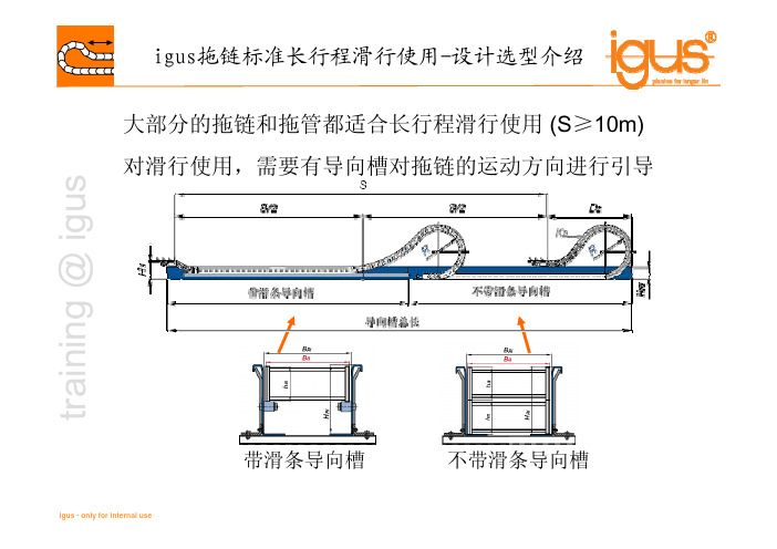
t r a i n i n g @ i g u s 大部分的拖链和拖管都适合长行程滑行使用(S ≥10m)对滑行使用,需要有导向槽对拖链的运动方向进行引导带滑条导向槽不带滑条导向槽t r a i n i n g @ i g u s 长行程拖链设计选型步骤:1.收集设计参数,包括:行程,速度,加速度,使用频率,工况,内部管线的直径、重量及最小弯曲半径,系统安装空间2.根据内部管线确定拖链弯曲半径(弯曲半径越小,拖链承载能力越大)3.根据拖链内部管线重量确定拖链型号(参考设计选型表)4.校核拖链的最大驱动力F PPFt r a i n i n g @ i g u s 何谓驱动力?F friction.F acc.F a 为拖链运动时最大加速度g =10m/s²µ= 摩擦系数F acc (m x a) + F 摩擦(m x µx g)= F PPFm 为拖链的质量(含在拖链内的管线重量),单位为kgt r a i n i n g @ i g u s注:设计选型表的数据都是基于以下使用条件时¾拖链根据图纸要求,采用降低高度安装¾V ≤1m/s¾环境温度+5°C 到+ 50°C¾环境湿度不超过70 %¾igus 标准材料的拖链(黑色)对超过以上条件的使用环境,拖链的型号需要进一步校核,请联系igus 的专业工程师t r a i n i n g @ i g u s 是否需要使用支撑板?¾当实际驱动力超过许用驱动力50%的时候,移动端需使用支撑板(推荐支撑板角度10~15°,长度约为3节拖链)不带支撑板带支撑板PPFP P FPPF PPF 此处受力最大t r a i n i n g @ i g u s Questions?Answers?Comments?Thank you for your attention!。
拖链电缆SPC-LiYCP

拖链电缆SPC-LiYCPSPCDATA-CHAIN-PUR-LiYCP高柔性聚氨酯拖链数据电缆PUR 高柔性数据传输拖链电缆电缆名称:SPCDATA-CHAIN-PUR-LiYCP高柔性聚氨酯数据拖链电缆PUR 高柔性数据传输拖链电缆LiYCP柔性数据拖链电缆柔性拖链电缆LiYCP 柔性数据传输拖链电缆LiYCP德标数据拖链电缆LiYCP数据拖链电缆LiYCP欧标柔性数据拖链电缆LiYP欧标数据拖链电缆LiYCP信号电缆LiYCP信号传输电缆LiYCP数据传输电缆数据电缆数据传输电缆PVC 数据电缆PVC数据传输电缆PVC柔性数据传输电缆柔性数据传输电缆信号电缆信号传输电缆RS485串口线高柔性聚氨酯电缆RS485信号线RS485信号传输电缆拖链电缆高柔性拖链电缆聚氨酯拖链电缆聚氨酯数据拖链电缆聚氨酯护套数据拖链电缆电缆应用:动力拖链或移动机械部件计算机系统、电子设备、电气成套、仪器仪表、办公设备、自动化系统、工业电子系统、安防系统等数据和信号传输需要出色的机械性能和耐化学性能的工业环境需要抗电磁干扰的环境适合干燥或潮湿的室内移动安装在指定使用温度范围内,才可用于户外电缆结构:导体:多股精绞细丝导体,符合VDE 0295及IEC 60288第6类导体绝缘:特殊PVC混合料芯线:芯线绞合成缆,芯线颜色符合DIN 47100 色标,无重复颜色屏蔽:镀锡铜线编织,编织密度≥80%护套:特殊PUR混合料护套颜色:黑色或灰色,可根据客户需要定选用各种颜色电缆特性:电缆的长期工作温度应不超过70℃低粘性表面、耐磨、抗撕裂、耐油、抗紫外线能承受中等的机械应力具有较强的抗电磁干扰能力适用于拖链系统中频繁连续弯曲600万次电缆技术参数:< 0.25mm2时:工作电压350 V 测试电缆1200V≥ 0.25 mm2时:工作电压500 V 测试电缆1500V导体电阻20℃:根据VDE 0295及IEC 60228第6类绝缘电阻:≥ 20 MΩ/km (20℃)互电容:C/C:最大120 nF/kmC/S:大约160 nF / km电感:约0.65 mH/km最小弯曲半径:固定安装5 X D(电缆外径)移动安装:当行程<10米时,弯曲半径为10 X D(电缆外径)当行程≥10米时,弯曲半径为12 X D(电缆外径)移动特性:敷设行程:80米,加速度50米/秒2,移动速度≤5米/秒弯曲寿命:30次/分钟,>600万次工作温度:固定安装- 40 ~ +80℃移动安装- 30 ~ +70℃外护套抗油性:符合IEC60811-2-1电缆名称电缆型号额定电压对数导体结构标称截面mm2高柔性聚氨酯数据拖SPCDATA-CHAIN-LiYCP 350V 1 ~ 100 多股精绞细丝导体0.12 ~ 0.22 链电缆屏蔽型高柔性聚氨酯数据拖SPCDATA-CHAIN-LiYCP 500V 1 ~ 100 多股精绞细丝导体0.25~ 1.5 链电缆屏蔽型注:以上规格为常用型,可根据用户要求定制特殊规格。
拖链电缆
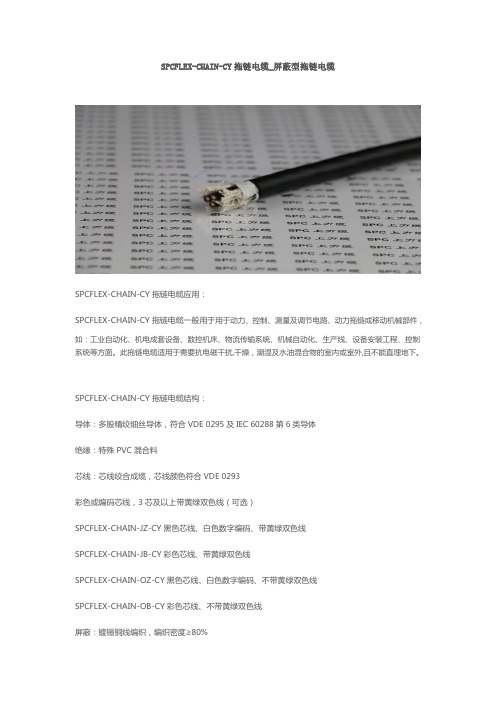
SPCFLEX-CHAIN-CY拖链电缆_屏蔽型拖链电缆SPCFLEX-CHAIN-CY拖链电缆应用:SPCFLEX-CHAIN-CY拖链电缆一般用于用于动力、控制、测量及调节电路、动力拖链或移动机械部件,如:工业自动化、机电成套设备、数控机床、物流传输系统、机械自动化、生产线、设备安装工程、控制系统等方面。
此拖链电缆适用于需要抗电磁干扰,干燥,潮湿及水油混合物的室内或室外,且不能直埋地下。
SPCFLEX-CHAIN-CY拖链电缆结构:导体:多股精绞细丝导体,符合VDE 0295及IEC 60288第6类导体绝缘:特殊PVC混合料芯线:芯线绞合成缆,芯线颜色符合VDE 0293彩色或编码芯线,3芯及以上带黄绿双色线(可选)SPCFLEX-CHAIN-JZ-CY黑色芯线、白色数字编码、带黄绿双色线SPCFLEX-CHAIN-JB-CY彩色芯线、带黄绿双色线SPCFLEX-CHAIN-OZ-CY黑色芯线、白色数字编码、不带黄绿双色线SPCFLEX-CHAIN-OB-CY彩色芯线、不带黄绿双色线屏蔽:镀锡铜线编织,编织密度≥80%护套:特殊改性PVC混合料护套颜色:黑色、灰色或橙色,可根据客户需要定选用各种颜色SPCFLEX-CHAIN-CY拖链电缆特性:SPCFLEX-CHAIN-CY拖链电缆电缆的长期工作温度应不超过70℃,其具有防水、耐油、耐寒、耐磨、抗紫外线,能承受中等的机械应力等优点,且具有较强的抗电磁干扰能力,用于拖链系统中频繁连续弯曲能达300万次。
其阻燃特性符合VDE 0472-804部分B类测试标准和IEC 60332-1-2SPCFLEX-CHAIN-CY拖链电缆技术参数:工作电压:300/500V 450/750V 600/1000V测试电缆:2000V 2500V 3500V导体电阻20℃:根据VDE 0295及IEC 60228第6类绝缘电阻:≥20 MΩ/km (20℃)最小弯曲半径:固定安装6 X D(电缆外径)移动安装:当行程<10米时,弯曲半径为10 X D(电缆外径)当行程≥10米时,弯曲半径为12 X D(电缆外径)移动特性:敷设行程:50米,加速度20米/秒2,移动速度≤2米/秒弯曲寿命:30次/分钟,>300万次工作温度:固定安装-30 ~ +70℃移动安装- 5 ~ +70℃护套抗油性:符合IEC60811-2-1。
拖链电缆组件,机器人拖链,坦克拖链,非标自动化拖链线束
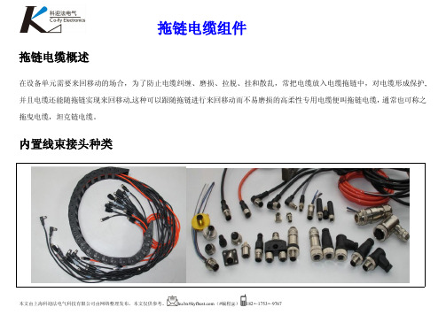
拖链电缆概述在设备单元需要来回移动的场合,为了防止电缆纠缠、磨损、拉脱、挂和散乱,常把电缆放入电缆拖链中,对电缆形成保护,并且电缆还能随拖链实现来回移动,这种可以跟随拖链进行来回移动而不易磨损的高柔性专用电缆便叫拖链电缆,通常也可称之拖曳电缆,坦克链电缆。
内置线束接头种类系列产品芯数实物插座安装方式插头M52PIN,3PIN,4PIN面板前固定,面板后固定,焊接预制带线,自接线,屏蔽式,直型,90弯°型M62PIN,3PIN,4PIN面板前固定,面板后固定,焊接预制带线,自接线,屏蔽式,直型,90弯°型M82PIN,3PIN,4PIN,5PIN面板前固定,面板后固定,焊接预制带线,自接线,屏蔽式,直型,90弯°型M122PIN,3PIN,4PIN,5PIN,6PIN,8PIN,12PIN,17PIN面板前固定,面板后固定,焊接预制带线,自接线,屏蔽式,直型,90弯°型5/82PIN,3PIN,4PIN,5PIN,6PIN,8PIN面板前固定,面板后固定,焊接预制带线,自接线,屏蔽式,直型,90弯°型M162PIN,3PIN,4PIN,5PIN,6PIN,8PIN面板前固定,面板后固定,焊接预制带线,自接线,屏蔽式,直型,90弯°型7/82PIN,3PIN,4PIN,5PIN,6PIN,8PIN面板前固定,面板后固定,焊接预制带线,自接线,屏蔽式,直型,90弯°型M232PIN,3PIN,4PIN,5PIN,6PIN,8PIN,9PIN,12PIN,19PIN面板前固定,面板后固定,焊接预制带线,自接线,屏蔽式,直型,90弯°型以太网百兆以太网,千兆以太网面板前固定,面板后固定,焊接预制带线,自接线,屏蔽式,直型,90弯°型USBUSB 转接延长线面板前固定,面板后固定,焊接预制带线,自接线,屏蔽式,直型,90弯°型Min-50152PIN,3PIN,4PIN,5PIN,6PIN,8PIN,9PIN,12PIN,19PIN 等面板前固定,面板后固定,焊接预制带线,自接线,屏蔽式,直型,90弯°型RS485多接口分线盒2PIN,3PIN,4PIN,5PIN,6PIN,8PIN4口座,6口座,8口座,12口座等组成1.抗拉中心在电缆的中心根据芯数数量以及每根芯线交叉区域的空间里尽可能的有一个真正的中心线填充(而不是像通常情况下,用一些填充料或废塑料制成的垃圾芯线填充)这种方法能有效的保护绞线结构,防止绞线游离到电缆的中心区域。
- 1、下载文档前请自行甄别文档内容的完整性,平台不提供额外的编辑、内容补充、找答案等附加服务。
- 2、"仅部分预览"的文档,不可在线预览部分如存在完整性等问题,可反馈申请退款(可完整预览的文档不适用该条件!)。
- 3、如文档侵犯您的权益,请联系客服反馈,我们会尽快为您处理(人工客服工作时间:9:00-18:30)。
低烟无卤外护套拖链系统对绞屏蔽控制电缆
应用范围
低烟无卤外护套拖链系统对绞屏蔽控制电缆应用于高要求的运动场合,军工医院设备常用。
DUUSP电缆的特点
1.高柔抗拉
2.弯曲半径8倍电缆直径
3.防油污防日照防老化耐水碱等
4.保证工作的连续性
5.用于拖链系统大于600万次循环使用
电缆结构
导体材料:多股精绞成束裸铜丝。
导体结构:符合VDE类标准。
芯线绝缘:DVV混合料,抗撕裂,抗切割。
芯线绞合:芯线小节距绞合,对绞成缆。
芯线标识:红黄绿双。
屏蔽:镀锡铜丝屏蔽,屏蔽覆盖率85%以上。
外护套:低烟无卤聚氨酯。
耐磨抗拉。
技术指标
最小弯曲半径:8×电缆外径。
温度范围:-45℃~+80℃。
工作电压:450/700V
测试交流电压:2000~3000V。
执行标准:符合VDE、GB。