
多德Dold安全继电器bo5988使用说明书
1BO 5988.61BO 5988.48USA USA / Canada2Time delay t v :Auxiliary supply is not necessary during elapse of time:BO 5988.47/1 _ _ :0,1... 1 s 0,3... 3 s 0,5... 5 s 1...10 s BO 5988.47/2 _ _ :1 s, 3 s, 5 s, 10 sAuxiliary supply must be connected during elapse of time:BO 5988.47/4 _ _:0,1... 1 s 0,1... 1 min 0,3... 3 s 0,3 ... 3 min 1...10 s 0,5 ... 5 min 3...30 s 1...10 min BO 5988.47/5 _ _ : 1 s, 3 s, 10, 30 s1 min, 3 min, 5 min, 10 minRepeat accuracy BO 5988.47/1 _ _ and BO 5988.47/2 _ _ :+ 15 % of setting value BO 5988.47/4 _ _ and BO 5988.47/5 _ _ :+ 1 % of setting valueSetting accuracy BO 5988.47/1 _ _ and BO 5988.47/2 _ _ :upper half of scale:+ 25 % of end scale value lower half of scale:overvoltage category /contamination level: 4 kV / 2DIN VDE 0110-1 (04.97)EMCElectrostatic discharge:8 kV (air)EN 61 000-4-2HF irradiation:10 V / m EN 61 000-4-3Fast transients: 2 kVEN 61 000-4-4Surge voltages betweenwires for power supply:0,5 kV EN 61 000-4-5between wire and ground: 2 kV EN 61 000-4-5HF-wire guided:10 V EN 61 000-4-6Interference suppression:Limit value class B EN 55 011Degree of protection:Housing:IP 40EN 60 529Terminals:IP 20EN 60 529Housing:Thermoplastic with V0 behaviour according to UL subject 94Vibration resistance:Amplitude 0,35 mm EN 60 068-2-6frequency 10 ... 55 Hz Climate resistance:15 / 050 / 04EN 60 068-1Terminal designation:EN 50 005Wire connection:1 x 4 mm2 solid or2 x 1,5 mm 2 stranded wire with sleeve DIN 46 228Contacts BO 5988.48: 3 NO, 1 NC indicator contact BO 5988.61: 6 NO, 1 NC indicator contact BO 5988.62: 6 NO, 1 NO indicator contact BO 5988.47:3 NO, 1 NC indicator contact 1 NO delayed Operate time manual restart:typ. 30 ms automatic restart: 1 sRelease timeopening in secondary circuit (S12-S22):30 ms + 50 %opening in supply circuit BO5988.47, BO 5988.48:100 ms + 50 %BO 5988.61, BO 5988.62:50 ms + 50 %Line fault detection at the On pushbutton:The output contacts cannot be closed if the On pushbutton is already closed before the voltage is applied to S12, S22 (also in the event of a line fault at the On pushbutton).A line fault at the On pushbutton which occures after activation of the device is recognized when swichting-on takes place again and closing of the output contacts is then prevented.If a line fault occurs at the On pushbutton after the voltage is already present at S12, S22, undesired activation will take place, because this line fault does not differ from the normal closing function.The gold-plated contacts of the BO 5988 also mean that this module is suitable for switching small loads of 1 mVA ... 7 VA, 1 mW ... 7 W in the range 0,1 ... 60 V, 1 ... 300 mA. The contacts also permit the maximum switching current. However, since the gold plating is burnt off at this current level, the device is no longer suitable for switching small loads after this.The PE terminal permits operation of the device in IT systems with insulation monitoring and also serves as a reference point for testing the control voltage. The internal short-circuit protection will be bridged on DC devices, if the protective ground is connected to terminal PE.One or more extension modules BN 3081 or external contactors with positively-driven contacts may be used to multiply the number of contacts of the emergency stop module BO 5988.3Limit curve for arc-free operation with resistive loadGeneral formula for determination of the maximum ambient temperatureA)Sum of currents 2 per safety contact = value on scale S I 2 (A 2)B)Max. ambient temperature T = Cross point of scale S I 2 (A 2)with limit curve Example 1A)(4A)2 + (4A)2 + (4A)2 + (4A)2 + (4A)2 + (4A)2 = 96 A 2 (Scale S I 2)B)Max. ambient temperature T = 43°C (point 1)Example 2A)(0,5 A)2 + (1 A)2 + (2 A)2 + (1 A)2 = 6,25 A 2 (Scale S I 2)B)Max. ambient temperature T = 49°C (point 2)Please note:The total current 2 can still be 1,5 A 2 at 50°C , i.e. 0,5 A per safety contact A)(0,5 A)2 + (0,5 A)2 + (0,5 A)2 + (0,5 A)2 + (0,5 A)2 +( 0,5 A)2 = 1,5 A 2B)Max. ambient temperature = 50°C Two-channel emergency stop circuit without cross fault detection.Activation via On pushbutton. - - - Jumper X5 - X6:A jumper must be fitted X5 - X6 for the automatic On function.The On pushbutton is not required.Wire fixing:Plus-minus terminal screws M 3,5box terminal with wire protection Mounting:DIN rail EN 50 022Weight:850 gDimensionsWidth x height x depth:100 x 74 x 121 mmTotal current limit curveIt is necessary to use the square of the currents in order to obtain a linearlimit curve.BO 5988.61/024 DC 24 V + AC 230 V 50 / 60 Hz Article number:0040375stock item·Dual voltage version·Output: 6 NO, 1 NC contacts as monitoring contact ·Width: 100 mmBO 5988.47/124 DC 24 V + AC 230 V 50 / 60 Hz 1 ...10 s Article number:0040430stock item ·Dual voltage version·Output: 3 NO, 1 NC contacts as monitoring contact, 1 NO contact ·With adjustable time delay t v to 10 min.·Width: 100 mm BO 5988._ _ /60:with CSA approval BO 5988._ _ /61:with UL approval (Canada/USA)Auxiliary supply is not nesseary during elapse of time:BO 5988.47 / 1 _ _: 3 NO / 1 NC contacts + t v adjustable BO 5988.47 / 2 _ _: 3 NO / 1 NC contacts + t v fixed Auxiliary supply must be connected during elapse of time:BO 5988.47 / 4 _ _: 3 NO / 1 NC contacts + t v adjustable BO 5988.47 / 5 _ _: 3 NO / 1 NC contacts + t v fixed Without time delay t v :BO 5988.48 / 0_ _ : 3 NO / 1 NC contacts BO 5988.61 / 0_ _ : 6 NO / 1 NC contacts as monitoring contact BO 5988.62 / 0_ _ : 6 NO / 1 NC contacts as monitoring contact BO 5988. _ _ / _00:single voltage model BO 5988. _ _ / _24:dual voltage model BO 5988.61 / 106:Protective seperation of control and load circuits according to VDE 0106 part 101 4 kV / 2 referred to overvoltage category II with basic insulation to VDE 0110 of 2,5 kV / 2.BO 5988.61 / 324:Dual voltage model 0,5 s operate delay withautomatic restart Ordering example for VariantsBO 5988.47/124 1 ... 10 s DC 24 V + AC 230 V50 / 60 HzNominal frequency Nominal voltage Time delay00: 1 nominal voltage 24: 2 nominal votlages 0: without t vwithout auxiliary supply during time elapse:1: t v adjustable 2: t v fixedwith auxiliary supply during time elapse:4: t v adjustable 5: t v fixed Contacts Type4Contact reinformcement by external contactors with reduced safety level.Two-channel monitoring of a safety gate. S1 must not close before S2One-channel emergency stop circuit. This circuit does not have any redundancy in the emergency stop control device circuit.Two-pole emergency stop circuit with emergency stop control device in the supply circuit.Application for long emergency stop loops where the control voltage drops below the minimum voltage of 21 V.Attention:Single faults (e.g. line faults at the emergency stop control device) are not detected with this external circuit configuration.Contact reinforcement by external contactors, two-channel.The output contacts can be reinforced by external contactors with positively-driven contacts for switching currents > 8 A. Functioning of the external contactors is monitored by looping the NC contacts into the closing circuit (terminals X1 - X2).Two-channel emergency-stop circuit with cross fault detection.Activation via On pushbutton. - - - Jumper X5 - X6:A jumper must be fitted X5 - X6 for the automatic On function.The On pushbutton is not required.E. DOLD & SÖHNE KG • D-78114 Furtwangene-mail dold-relays@t-online.de • internet •Postf. 1251 • Tel. +49 7723 654 0 • Telefax +49 7723 654 356。
德国P+F 音叉式开关使用说明书

27
10 ... 55 V DC, PNP, 3-线 , V1-连接器 • LVL-S1-G3O-E5V1-NA, 抛光克音叉 表 面, Ra < 1.5 mm • LVL-S1-T5O-E5V1-NA, 抛光音叉表面 1½", 过 程连接三夹具, Ra < 1.5 mm 所有以上型号都有螺纹1NPT型。
30 41
19
1 NPT
120 ... 126 mm ~99 mm
最大 . 150 ˚C/25 bar 最大 . 100 ˚C/40 bar
过程连接 N3 = 1 NPT
~30 41 19
128
最大 . 150 ˚C/25 bar 最大 . 100 ˚C/40 bar
过程连接 G3 = G1A
安装附件:焊接适配器(不带音叉校正)带FPM O环 (氟化橡校)LVL-Z61
技术参数 型号
LVL –S1 –
– E 5 V 1 –NA
认证 NA 无认证 特性 V1 连接器 M12 x 1; V1 电气输出 E5 10 V DC ... 55 V DC, PNP, 3-线 音叉表面 S 标准表面 , Ra < 3.2 mm O 抛光型 , Ra < 1.5 mm G 高抛光型 , Ra < 0.5 mm 过程连接 S1 齐平安 装 ,用于焊接适, 1.4571 G3 螺 纹 G1 BSP, 1.4571 M7 DN50 卫生耦合 器 DIN 1185, 1.4571 T6 三夹具 2" ISO 2852, 1.4571 T5 三夹具 1½" ISO 2852, 1.4571
euchner esm-ba3.. 紧急停机安全继电器 用户手册说明书
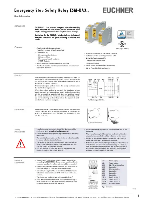
V1.1.0• Cyclical monitoring of the output contacts • Indication of the switching state via LED • 2 start behaviors possible: - Monitored manual start - Automatic start• Short circuit and earth fault monitoring • Up to PL e, SILCL 3, category 4Correct UseThe ESM-BA3.. is a universal emergency stop safety switching device with three safe relay outputs that can quickly and safely stop the moving parts of a machine or system in case of danger. Applications for the ESM-BA3..include singleor dual-channel emergency stop circuits and guard monitoring on machines and systems.Features• 3 safe, redundant relay outputs1 auxiliary contact (signaling contact) • Connection of:- Emergency stop buttons - Safety switches- Non-contact safety switches - OSSD-Outputs• Single and dual-channel operation possible• Feedback loop for monitoring downstream contactors or expansion modulesFunctionThe emergency stop safety switching device ESM-BA3.. is designed for safe isolation of safety circuits according to EN 60204-1 and can be used up to safety category 4, PL eaccording to EN ISO 13849-1.The internal logical system closes the safety contacts when the start button is pressed.When the safety switch is opened, the positively driven safety contacts are opened and safely switch the machine off. It is ensured that a single fault does not lead to a loss of the safety function and that every fault is detected by cycli-cal self-monitoring no later than when the system is swit-ched off and switched on again.Electrical Connection• When the 24 V version is used, a safety transformeraccording to EN 61558-2-6 or a power supply unit with electrical isolation from the mains must be connected. • External fusing of the safety contacts (6A slow-blow or 8A quick-action or 10 A gG) must be provided.•A maximum length of the control lines of 1000 meters with a line cross section of 0.75 mm 2 must not be ex-ceeded.• The line cross section must not exceed 2.5 mm 2. •If the device does not function after commissioning, it must be returned to the manufacturer unopened. Ope-ning the device will void the warranty.InstallationAs per EN 60204-1, the device is intended for installation in control cabinets with a minimum degree of protection of IP54. It is mounted on a 35 mm DIN rail according to DIN EN 60715 TH35.SafetyPrecautionsFig. 1 Block diagram ESM-BA3..Fig. 2 Installation / removalFig. 3 ConnectionsA1: Power supply A2 : Power supplyS11: DC 24V control voltage S10: Control line S21: Start control line S13: Control line S14: Control line S12: Control line13-14: Safety contact 1 23-24: Safety contact 2 33-34: Safety contact 3 41-42: Auxiliary contact(not for plug-in terminals)• All relevant safety regulations and standards are to beobserved.• The overall concept of the control system in which the device is incorporated must be validated by the user. • Failure to observe the safety regulations can result in death, serious injury and serious damage.• Note down the version of the product (see label “Vx.x.x”) and check it prior to every commissioning of a new de-vice. If the version has changed, the overall concept of the control system in which the device is incorporated must be validated again by the user.• Installation and commissioning of the device must be performed only by authorized personnel .• Observe the country-specific regulations when installing the device.• The electrical connection of the device is only allowed to be made with the device isolated.•The wiring of the device must comply with the instruc-tions in this user information, otherwise there is a risk that the safety function will be lost.•It is not allowed to open the device, tamper with the device or bypass the safety devices.V1.1.0Note: The items listed under “Electrical connection” must be observed during commissioning. Commissioning Procedure1. Wiring emergency stop circuit:Wire the emergency stop circuit according to the required Performance Level determined (see Fig. 1 to Fig. 5). 2. Wiring start circuit:Wire the start circuit according to Fig. 6 or Fig. 7 to set the starting behavior. Warning:If “Automatic start” is set, bear in mind that the safety con-tacts will switch immediately after the power supply is connected. If “Monitored manual start” is set, the start button must be opened after wiring. 3. Wiring feedback loop:If your application provides for external contactors or ex-pansion modules, connect them to the device according to Fig.8 or Fig. 9.4. Wiring power supply:Connect the power supply to terminals A1 and A2 (Fig. 10). Warning: Wiring only in de-energized state.5. Starting the device:Switch the operating voltage on. Warning:If the “Automatic start” starting behavior is set, the safety contacts will close immediately.If the “Monitored manual start” starting behavior is set, close the start button to close the safety contacts. LEDs K1 and K2 are lit.6. Triggering safety function:Open the emergency stop circuit by actuating the connec-ted safety switch. The safety contacts open immediately. 7. Reactivation:Close the emergency stop circuit. If “Automatic start” is selected, the safety contacts will close immediately.If the “Monitored manual start” starting behavior is set, close the start button to close the safety contacts.Fig. 6:Monitored manual start. It is monitored that the start button was opened before the emergency stop button closes. (Prerequisite: operating voltage must not be interrupted.)Fig. 7:Automatic start.Max perm. delay during closing of the safety switches on S12 and S13:S12 before S13: 300 ms S13 before S12: anyWarning:Safety contacts switch immediately when thepower supply is connected.Depending on the application or the result of the risk assessment according to EN ISO 13849-1, the device must be wired as shown in Fig. 1 to Fig. 11.ApplicationsFig. 3:Single-channel emergency stop circuit with earth fault monitor-ing.(category 1, up to PL c)Fig. 2:Two-channel emergency stop circuit with earth fault monitoring. (category 3, up to PL d)Fig. 1:Two-channel emergency stopcircuit with short circuit and earth fault monitoring.(category 4, up to PL e)Fig. 4:Two-channel sliding guardmonitoring with short circuit and earth fault monitoring. (category 4, up to PL e)Emergency Stop CircuitStarting BehaviorFig. 5:Two-channel emergency stop with pnp-outputs/OSSD-outputs with short circuit monitoring. (category 4, up to PL e)Fig. 8:Feedback loop for monitored manual start:The feedback loop monitors contactors or the expansion modules .Feedback LoopFig. 9:Feedback loop for automatic start: The feedback loop monitors contac-tors or the expansion modules .Power supply andSafety contactsFig. 10:Power supply A1 and A2.(Power supply according to techn. data )Fig. 11:Connecting load to safety contacts.(Figure shows example.Voltage …+V“ according to techn. data)Notice:In order to activate earth fault monitoring, S10 must be con-nected to PE (protective earth) on the AC115/230V devices. With AC/DC 24V, connect PE only to the power supply unit according to EN60204-1.V1.1.0MaintenanceThe device must be checked once per month for proper function and for signs of tampering and bypassing of the safety function.Techn. DataOperating voltage ESM-BA301 ESM-BA302 ESM-BA303AC/DC 24V AC 115V AC 230V Rated supply frequency 50-60 Hz Permissible deviation + / - 10% Power consumption DC 24V AC 230Vapprox. 2.3 W approx. 6.9 VA Control voltage at S11 DC 24 VControl current S11...S14 approx. 60 mA Safety contacts 3 NO contacts Auxiliary contacts 1 NC contact Max. switching voltageAC 250 VSafety contact breaking capacity (13-14, 23-24, 33-34) AC: 250 V, 2000 VA, 8 A for ohmic load, 250 V, 3 A for AC-15DC: 50 V, 400 W, 8 A for ohmic load; 24 V, 3 A for DC-13Max. total current through all 3 contacts15 A (13-14, 23-24, 33-34) *)Auxiliary contact breaking capacity (41-42) AC: 250 V, 500 VA, 2 A for AC-12 DC: 50 V, 100 W, 2 A for DC-12 Minimum contact load 24 V, 5 mAContact fuses 6 A slow-blow or 8 A quick-action or 10 A gG Line cross section 0.14 - 2.5 mm 2Max. length of control line 1000 m with 0.75 mm 2 Contact material AgNiContact service life mech. approx. 1 x 10⁷Test voltage2.5 kV (control voltage/contacts) Rated impulse withstand voltage, leakage path/air gap 4 kV (DIN VDE 0110-1) Rated insulation voltage 250 V Degree of protection IP20Temperature range -15°C to +40°C *) Degree of contamination 2 (DIN VDE 0110-1) Overvoltage category 3 (DIN VDE 0110-1) Weight approx. 230 gMounting DIN rail according to EN 60715TH35SafetyCharacteristics According to EN ISO 13849-1Note:Additional data can be requested from the manufacturer for applications that deviate from these conditions.The device is certified according to EN ISO 13849-1 up to a Performance Level of PL e.Device cannot be switched on again after an emergency stop:• Check whether the emergency stop circuit was closed again.• Was the start button opened before closing of the emer-gency stop circuit (with manual start)? • Is the feedback loop closed?If the fault still exists, perform the steps listed under “Commissioning Procedure”.If these steps do not remedy the fault either, return the device to the manufacturer for examination.Opening the device is impermissible and will void the warranty.Device does not switch on:• Check the wiring by comparing it to the wiring diagrams. • Check the safety switch used for correct function and adjustment.• Check whether the emergency stop circuit is closed. • Check whether the start button (with manual start) is closed.• Check the operating voltage at A1 and A2. •Is the feedback loop closed?What to Do in Case of a Fault?The device is otherwise maintenance free, provided that it was installed properly.*) If several ESM-BA3.. devices are closely spaced under load, the max. total current at the ambient temperature of T=20°C: 9A; at T=30°C: 3A; at T=40°C =1A. If these currents are exceeded, a spacing of 5 mm between the devices must be observed.Safety characteristics according to EN ISO 13849-1 for all variants of ESM-BA3 Load (DC-13; 24V) <= 0,1A <= 1A <= 2A T10d [years] 20 20 20 Category: 4 4 4 PLe e e PFHd [1/h]: 1,2E-08 1,2E-08 1,2E-08 nop [cycle / year]<= 500.000<= 350.000<= 100.000V1.1.0Dimension DrawingS u b j e c t t o t e c h n i c a l m o d i f i c a t i o n s , n o r e s p o n s i b i l i t y i s a c c e p t e d f o r t h e a c c u r a c y o f t h i s i n f o r m a t i o n . © E U C H N E R G m b H + C o . K G 090073-05-05/14 (T r a n s l a t i o n o f t h e O r i g i n a l O p e r a t i n g I n s t r u c t i o n s )。
Bosch D9068 数字消防报警传输器(DACT)说明书
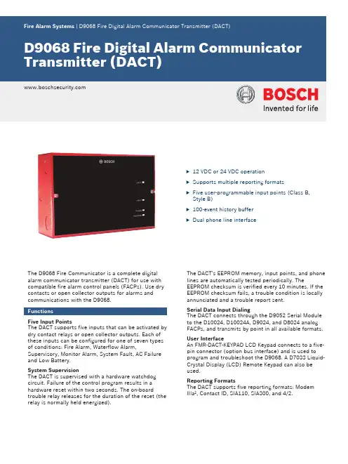
u12 VDC or 24 VDC operationu Supports multiple reporting formatsu Five user-programmable input points (Class B, Style B)u100-event history bufferu Dual phone line interfaceThe D9068 Fire Communicator is a complete digital alarm communicator transmitter (DACT) for use with compatible fire alarm control panels (FACPs). Use dry contacts or open collector outputs for alarms and communications with the D9068.FunctionsFive Input PointsThe DACT supports five inputs that can be activated by dry contact relays or open collector outputs. Each of these inputs can be configured for one of seven types of conditions: Fire Alarm, Waterflow Alarm, Supervisory, Monitor Alarm, System Fault, AC Failure and Low Battery.System SupervisionThe DACT is supervised with a hardware watchdog circuit. Failure of the control program results in a hardware reset within two seconds. The on‑board trouble relay releases for the duration of the reset (the relay is normally held energized).The DACT's EEPROM memory, input points, and phone lines are automatically tested periodically. The EEPROM checksum is verified every 10 minutes. If the EEPROM checksum fails, a trouble condition is locally annunciated and a trouble report sent.Serial Data Input DialingThe DACT connects through the D9052 Serial Module to the D10024, D10024A, D9024, and D8024 analog FACPs, and transmits by point in all available formats. User InterfaceAn FMR‑DACT‑KEYPAD LCD Keypad connects to a five-pin connector (option bus interface) and is used to program and troubleshoot the D9068. A D7033 Liquid-Crystal Display (LCD) Remote Keypad can also be used.Reporting FormatsThe DACT supports five reporting formats: ModemIIIa2, Contact ID, SIA110, SIA300, and 4/2.Report RoutingThere are six different report groups that can be routed to one of four phone settings. These report groups consist of non-supervisory alarms, supervisory alarms, alarm restorals, resets, supervisory restorals, tests and troubles, and trouble restorals.Reset ReportA reset report is sent when the D9068 resets from any off-normal condition.Phone Line SelectionThe DACT follows a pre‑determined sequence to select between the phone lines. It also implements the new NFPA requirements for alternation of phone lines during test reporting. The DACT maintains a variable that selects either Phone Line 1 or Phone Line 2 for automatic test reports. After each successful test report, the variable switches to select the other phone line.Communication Failed IndicationThe DACT indicates a communication failure after ten attempts to communicate are completed without success. This causes the trouble output to activate and report the fault.History BufferThe DACT has a history buffer that retains up to 100 events. Each event is tagged with the date and time of occurrence. This buffer can be viewed when anFMR‑DACT‑KEYPAD LCD Keypad (or a D7033 LCD Remote Keypad) is connected to the D9068. When the buffer is full, old events are discarded to make room for new events.Lightning SuppressionMOVs and spark gaps suppress lightning surges and static discharges for inputs and telephone interface.Installation/configuration notesCompatible ProductsThe following products are compatible with the D9068 Fire DACT:Category Product ID Product Description Control Panels D7022Conventional FACPD8024Analog FACPD9024Analog FACPD10024Analog FACPD10024A Analog FACP Keypads andAnnunciatorsD7033LCD keypadFMR‑DACT‑KEYPAD LCD keypad Modules D9052Serial interface moduleponent1D9068 board1Metal enclosure (red)1Lightpipe1DCT-HWD hardware kitEnvironmental ConsiderationsMechanical PropertiesOutputsPower Requirements (use power-limited source)Ordering informationD9068 Fire Digital Alarm Communicator Transmitter (DACT)Complete digital alarm communicator transmitter (DACT) for use with compatible fire alarm control panels (FACPs)Order number D9068Represented by:Americas:Europe, Middle East, Africa:Asia-Pacific:China:America Latina:Bosch Security Systems, Inc. 130 Perinton Parkway Fairport, New York, 14450, USA Phone: +1 800 289 0096 Fax: +1 585 223 9180***********************.com Bosch Security Systems B.V.P.O. Box 800025617 BA Eindhoven, The NetherlandsPhone: + 31 40 2577 284Fax: +31 40 2577 330******************************Robert Bosch (SEA) Pte Ltd, SecuritySystems11 Bishan Street 21Singapore 573943Phone: +65 6571 2808Fax: +65 6571 2699*****************************Bosch (Shanghai) Security Systems Ltd.201 Building, No. 333 Fuquan RoadNorth IBPChangning District, Shanghai200335 ChinaPhone +86 21 22181111Fax: +86 21 22182398Robert Bosch Ltda Security Systems DivisionVia Anhanguera, Km 98CEP 13065-900Campinas, Sao Paulo, BrazilPhone: +55 19 2103 2860Fax: +55 19 2103 2862*****************************© Bosch Security Systems 2014 | Data subject to change without notice 2737918475 | en, V2, 04. Sep 2014。
德力西 CDYE电涌保护器 说明书

CDYE电涌保护器使用说明书安装、使用产品前,请仔细阅读使用说明书并妥善保管、备用安全告知在安装、操作、运行、维护、检查之前,请务必认真阅读本说明书,并按照说明书上的内容准确安装、使用本产品。
危险:●严禁湿手操作电涌保护器;●使用中,严禁触摸导电部位;●维护与保养时,必须确保产品不带电;注意:●安装、维护与保养时,应由具有专业资格的人员操作;●使用前请确认产品可持续工作电压、标称放电电流、电压保护水平是否符合工作要求;●指示窗口显示红色表示产品已经损坏,需要更换。
●SPD的火线支路上应串联后备保护用的SCB、保险丝或断路器,接地系统要有良好的连接。
●产品报废时,请做好废弃物处理,谢谢您的合作。
目录1主要用途及适用范围 (1)2产品面板介绍 (1)3正常使用、安装及运输条件 (2)3.1正常使用、安装条件 (2)3.2正常贮存和运输条件 (2)4技术特性 (3)4.1主要技术参数 (3)5外形及安装尺寸 (4)6安装和使用(维护) (5)6.1安装 (5)6.2维护与保养 (6)7开箱检查 (6)8公司承诺 (6)1主要用途及适用范围CDYE系列电涌保护器主要用于交流50Hz/60Hz、额定电压230V/400V的单相/三相配电系统,用于抑制瞬态过电压,泄放电涌能量,防止或减轻因雷击或操作引起的瞬态过电压对设备造成的损害。
2产品面板介绍CDYE-II/20、CDYE-II/40、CDYE-II/65CDYE-II/80、CDYE-II/120、CDYE-I+II/12.5说明:1进线端子 2接线符号 3德力西品牌4工作状态指示窗口:CDYE-II/20(/40/65): 绿色表示防雷功能正常,红色表示防雷功能失效。
CDYE-II/80(/120)、CDYE-I+II/12.5: 无色表示防雷功能正常,红色表示防雷功能失效。
5最大放电电流Imax/冲击电流Iimp 6模块型号7主要技术参数:In-标称放电电流,Imax-最大放电电流,Up-电压保护水平,Uc-最大持续工作电压,Iimp-冲击电流8认证标志 9产品型号 10遥信端子接线图 11出线端子 12遥信端子13 安装卡扣3正常使用、安装及运输条件3.1正常使用、安装条件(1)工作环境温度 -40℃~ +80℃;(2)安装地点的海拔不超过2000m;(3)大气的相对湿度在周围最高温度+40℃时不超过50%,在较低温度下可以有较高的相对湿度,例如20℃时的90%。
继电器的相关学问与使用 继电器如何操作

继电器的相关学问与使用继电器如何操作继电器是依据电磁效应设计而成一种可控型的开关器件,紧要有线圈、衔铁和触点构成,所起到的功能是弱电掌控强电、小电流掌控大电流。
在工业自动化、新能源汽车继电器是依据电磁效应设计而成一种可控型的开关器件,紧要有线圈、衔铁和触点构成,所起到的功能是弱电掌控强电、小电流掌控大电流。
在工业自动化、新能源汽车(高压接触器)、通讯行业有着广泛的应用。
下面介绍一下继电器的相关学问和使用方法。
继电器的工作原理继电器的输入端是线圈,输出端是机械触点。
当线圈两端加上合适的电压后,线圈中会有电流流过,电生磁,线圈的铁芯产生磁力,使的衔铁动作让触点动作。
继电器的作用继电器可以实现弱电掌控强电、小电流掌控大电流的作用。
例如工控行业,常常用到继电器来掌控交流电磁阀、交流电机等,而主控的核心是PLC。
用PLC来掌控继电器的线圈,交流负载接入触点的回路中,可以实现PLC掌控交流负载的目的。
继电器的关键参数继电器的关键参数有这么几个:线圈电压、触点容量和使用寿命。
所谓线圈电压,就是指继电器工作时加在线圈两端的额定电压,在购买继电器时;店家都会询问要买几伏的,就是指继电器的线圈电压,如5V继电器、12V继电器、24V继电器等。
触点容量,就是在掌控回路中触点最大能承受的工作电压和工作电流,假如5A/DC30V,10A/AC220V。
机械式继电器的触点都是具有使用寿命的,如其机械耐久性为10000次,5000次等。
继电器还有其他参数如,线圈功率、线圈电阻、释放电压等。
—专业分析仪器服务平台,试验室仪器设备交易网,仪器行业专业网络宣扬媒体。
相关热词:等离子清洗机,反应釜,旋转蒸发仪,高精度温湿度计,露点仪,高效液相色谱仪价格,霉菌试验箱,跌落试验台,离子色谱仪价格,噪声计,高压灭菌器,集菌仪,接地电阻测试仪型号,柱温箱,旋涡混合仪,电热套,场强仪万能材料试验机价格,洗瓶机,匀浆机,耐候试验箱,熔融指数仪,透射电子显微镜。
人民电器 RDJD8 系列剩余电流动作继电器 产品说明书
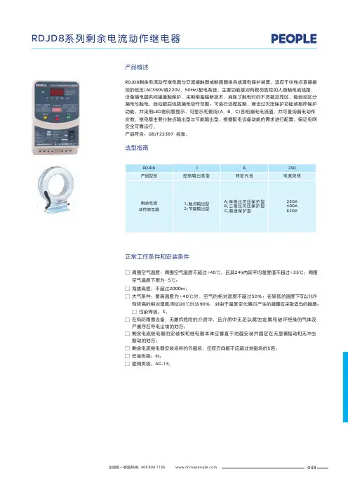
038RDJD8剩余电流动作继电器与交流接触器或断路器组合成涌电保护装置,适应于中性点直接接地的低压(AC380V 或220V 、50Hz )配电系统,主要功能是对有致命危险的人身触电或线路、设备漏电提供间接接触保护。
采用相鉴幅新技术,消除了触电时的不灵敏及死区,能自动区分漏电与触电。
自动跟踪线路漏电动作范围;可进行远程控制,增设过欠压保护功能或相序保护功能,并采用LED 数码管显示,可显示和查询(A 、B 、C )各相漏电电流值,并可查询漏电动作次数。
继电器主要分触点输出型与节能输出型,根据配电设备动能的需求进行配置,保证电网安全可靠运行。
产品符合:GB/T22387 标准。
□ 周围空气温度:周围空气温度不超过+40℃,且其24h 内其平均温度值不超过+35℃;周围 空气温度下限为-5℃;海拔高度:不超过2000m ;大气条件:最高温度为+40℃时。
空气的相对湿度不超过50%:在较低的温度下可以允 有较高的相对湿度,例如20℃时达90%.对由于温度变化偶尔产生的凝露应采取适当的措 污染等级:3;在有防雨雪设备、无爆炸危险的介质中,且介质中无足以腐蚀金属和破坏绝缘的气体及 严重存在导电尘埃的地方;剩余电流继电器的安装板和继电器本体应垂直于地面安装并固定在无显著摇动和无冲击 振动的地方;剩余电流继电器安装场所的外磁场,任何方向都不应超过地磁场的5倍;安装类别:III 使用类别:AC-15。
□ □ 许施;□ □ □ □ □ ;□ 正常工作条件和安装条件产品概述选型指南039主要技术参数□ 额定电压Un : 220V /380V ,额定频率:50Hz 。
□ 额定电流: 250A 、400A 、630A ;□ 互感器内径: 45mm (250A )、55mm (400A )、70mm (630A )、85mm (特订);□ 额定辅助电源电压Usn : AC220V ,其电压变化范围:(85%~110%)Usn ;□ 额定剩余动作电流: 可调(50 mA 、100mA 、300mA 、500mA ):□ 额定剩余动作电流自动跟踪: 50mA 、100mA 、200mA 、300mA 、500mA ;□ 脉冲突变动作电流: ≤50mA 、75mA ;□ 继电器触点容量: AC-15: 380V/0.47A 、250V/0.75A 、DC-13: 250V/0.27A □ 剩余电流继电器的分断时间(Ft ):Ft ≤0.2s 、0.3s 、0.5s 、1S ;□ 重合闸时间:20s~30s ;□ 额定短时耐受电流:6000A ;□ 欠压动作值单相:155V ±5%V (电压恢复正常后自动合闸)。
安全继电器接线功能详细介绍(中文)
PNOZ X3P产品描述安全继电器PNOZ X3P被封装在一个45mm p-99的塑壳里面。
该装置可以接24 (240)VAC/DC.的电源使用。
DescriptionThe Safety Relay PNOZ X3P is enclosed in a45 mm P-99 housing. The unit can beoperated with 24 ... 240 VAC/DC.特点•继电器输出:3对常开触点和一对辅助触点。
Positiveguided型触点。
(指采用机械方式联接使常开和常闭触点永远不能同时闭合的触点)•接线连接包括急停按钮、安全门限位开关、复位按钮。
•状态指示灯。
•扩展接触器/继电器的状态监视•晶体管有输出表明装置已备妥。
继电器兼容以下安全标准要求:•电路是含有内置自检功能的冗余设计--符合EN 954-1•在自身组件失效的情况下安全功能仍然起作用•安全功能继电器的正确开闭在每个on-off过程中被自动测试•继电器装有一只电子式保险Features:• Relay outputs: 3 safety contacts (N/O)and one auxiliary contact (N/C), positiveguided• Connections for Emergency Stop Button,Safety Gate Limit Switch and Resetbutton• Status Indicators• Monitoring of external contactors/relayspossible• Semi-conductor outputs show ready foroperationThe relay complies with the following safetyrequirements:• The circuit is redundant with built-in selfmonitoring(EN 954-1 Category 4).• The safety function remains effective in thecase of a component failure.• The correct opening and closing of thesafety function relays is testedautomatically in each on-off cycle.• The relays has an electronic fuse.功能描述Function DescriptionPNOZX3P为您提供一个安全趋向型的电路切断。
安全继电器设备安全操作规定
安全继电器设备安全操作规定背景介绍安全继电器是一种常见的电气自动控制器件,广泛应用于工业自动化领域中。
其主要作用是在生产过程中发现异常情况时,立即切断电源,保护人员和设备的安全。
但是,在实际运用中,由于工作人员的误操作或不当使用,安全继电器也可能存在一定的危险性。
为此,特制定本《安全继电器设备安全操作规定》,以保障人员和设备的安全。
安全继电器设备的基本知识安全继电器是指可以保护人员和设备安全的电器装置,通常由故障诊断电路、故障报警电路、截止电路和输出电路等部分组成。
安全继电器的主要功能是在工作过程中出现异常情况时,立即停止设备运行,以保障工作人员和设备的安全。
安全操作规定1. 安全继电器设备应在符合标准规定的地方放置,并由专业人员进行安装调试。
2. 安全继电器设备不得私自拆卸、更换元件等操作。
3.所有接触安全继电器设备的人员应接受专业的安全培训,并按照规定操作程序进行使用。
4.操作人员应当了解设备的工作原理及工作过程中的异常情况的处理方法,并按照规定程序进行操作。
5.设备应定期维护、保养,保持清洁、干燥,及时修复故障。
6.设备使用过程中,如发现任何故障,请立即报告设备所属部门,并请专业人员进行处理。
7.操作人员应定期进行设备安全检查,检查包括但不限于接触器触点、线路连接、故障指示灯、执行器运转情况等方面。
8.操作人员应对操作日志进行认真填写,注意记录运行状况、故障情况、处理方法、负责人等内容。
安全继电器设备的保养方法1. 定期对设备进行检查维护,及时清洁过滤部分、松动紧固件、补充润滑油等。
2. 检查设备电源连接的接线端子是否松动、氧化等。
3. 检查控制电路连接是否良好,检查接线端子连接是否紧固等。
4. 定期检查设备的故障报警电路。
5. 设备运行时应当保持清洁、干燥、通风良好等环境条件。
6. 定期检查设备的绝缘性能并记录。
结语以上是本文对安全继电器设备的基本知识、安全操作规定以及保养方法的详细介绍。
Donadini 电器电炉产品说明书
EDIZIONE 0297
POS. CODE 20 R70050060 21 R70060010 22 R70060030 23 R70060060 X
PIECES DESCRIPTION 1 STEAM OUTLET GASKET 2 SILICON COUPLING Ø 30 1 SILICON COUPLING Ø 40 1 SILICON COUPLING Ø 15 2 NOZZLE (See service manual)
7 R58002160 1 DOOR HANDLE PRONG PIN
8 R58002760 1 DOOR HANDLE PRONG COUPLER
9 R58003240 1 DOOR HANDLE BUTTON ROD
10 R58004270 1 DOOR HANDLE SPACER
11 R58004830 1 RING NUT M18x1
POS. CODE
PIECES DESCRIPTION
®
VG 105 H tav. A
3 2
19
5
20
016 40 004 2302 230797 DONADINI & C
21
17
18 16 1 13 10
4
9 14 15 7 68 12 11
POS. CODE
PIECES DESCRIPTION
ቤተ መጻሕፍቲ ባይዱ
19
20
21 10 5 18
17
16 15
9
11 12
POS. CODE
PIECES DESCRIPTION
1 R58003860 1 MOTOR GASKET BRASS FLANGE
DOLD多德产品
E. Dold & Söhne KG 多德电气多德电气((太仓太仓))有限公司1928年,Emil Dold 先生创建了DOLD (E. Dold & Söhne KG )公司,发展至今,在全球已有超500多名员工,是继电器领域的先驱者,是世界领先的专业继电器制造商。
基本信息栏 中文名: 多德 外文名: DOLD总部地点:德国福特万根市 成立时间:1928年目录产品 (4)1.继电器模块 (4)1.1安全模块 (4)1.2监控模块 (6)1.3功率电子模块 (7)1.4控制模块 (8)1.5楼宇自动化模块 (9)2.安全联动锁 (10)3.线路板继电器 (11)4.导轨式外壳 (13)产品1.继电器模块 1.1安全模块急停模块单通道双通道 带延时功能 ..安全门监控模块标准型 BD5985N 带矛盾控制 BN5986 安全开关带触点输出 NE5021 带半导体输出 NE5020用于安全开关组的控制单元 BG5925/920光幕/光栅控制模块标准型, LG5925/900带muting功能, BH5902 /01MF2双手控制模块BD5980NLG/BG/BH 5933安全地毯BG5925/920扩展模块\延时模块:用来扩展安全模块的输出触点LG/BG 5929,BN3081,UG6929, BG7925, BG7926速度\停机监控BH5932,UH5947BD5936, LH5946多功能安全监控:急停,安全门,光幕 .BH5910,BH5911无线安全模块RE 5910SAFEMASTER PRO 安全PLC1.2监控模块绝缘监控IL5880 ,MK5880N,RP5888,UP5862IL5881,SL5881,AN5892/800 直流系统 AN5873,AN5890 交直流系统剩余电流监控(接地系统) IL5882/SL5882 (交流,脉动直流) IP5883(交流,直流,)测量模块:过欠电压\电流,相序,功率因数,功率故障报警器1.3功率电子模块固态继电器\接触器软启动电机刹车模块固态换相接触器(电机正反转)简单的速度控制器多功能电机控制1.4控制模块总线控制CANOpen PLCIL5504接口继电器标准型, IK3070带主动导引触点型插拔型, OA5630, OA1.5楼宇自动化模块远程控制开关模块遥控开关IK8702, IK8717中央开关IK8703中央开关和开关组IK8805特定模块优先开关继电器IK8715步进开关继电器IK8831时间控制开关楼梯通道时间继电器IK8810带预警功能型IK8810/002节能型IK8810/004风扇控制时间继电器IK8810/0052.安全联动锁多德STS 安全联动锁系统是根据DIN EN ISO 13849标准设计,并通过TÜV 安全认证,STS 安全联动锁集安全开关,电磁锁和联动钥匙系统为一体。