ANSI-ASME B16.5 Flanges
ansi Flange 全

Texas Flange Product CatalogIllinois Office800-826-3801630-627-0642 fax 630-627-0515 local phoneHouston Office877-610-8924877-610-8893 fax 281-484-8325 local tel 281-484-8730 local faxInformation In this catalog was compiled from industry sources that Texas Flange & Fitting believes to be reliable. Texas Flange & Fitting Supply, Incorporated, however, does notguarantee the accuracy of this data.This Page is Linkable. This Catalog is Printable.• ANSI B16.5 - 150, 300, 400, 600, 900, 1500, 2500, weights– 150 & 300, 400 & 600, 900 thru 2500 • Flange Tolerances • ANSI B 16.47 Note• ANSI B 16.47 Series A Class 150, 300, 400, 600, 900 • ANSI B16.47 Series B Class 75, 150, 300, 400, 600, 900• ANSI B16.1- Industry Standard - Class 125LW, 125 SO, 125WN, 250 • Boiler Code Flanges - Class 75 SO, 75 WN, 175, 350 • Orifice Union B 16.35- Class 300 WN, SO, Threaded, WN - 400, 600, 900, 1500, 2500 • AWWA C207-Class 1B, 2D, 3D, 4E, 5E, 6F• Long Weld Necks - 150, 300, 400, 600, 900, 1500, 2500 • Studding Outlets - 150, 300, 600, 900, 1500, 2500 • Spectacle Blinds - 150, 300, 600, 900 • Wall Thickness and Bore Chart • RTJ Face Dimensions • Alternate Flange Facings • Bolting ChartTEXAS FLANGE CATALOGWe look forward to hearing from you.Phone: 877-610-8924 Fax: 877-610-8893 Email: jeff@ANSI B16.5 Class 150 Forged FlangesWeld Neck ThreadedSlip- OnLap Joint Socket Weld Blind Nom.Pipe Size O T1R XNo.2/Dia.of HolesBoltCircleDia.L21H B23L B r L34B3D½ 3.5 .44 1.38 1.19 4-0.62 2.38 1.88 .84 .62 .62 .88 .12 .62 .9 .38 ¾ 3.88 .5 1.69 1.5 4-0.62 2.75 2.06 1.05 .82 .62 1.09 .12 .62 1.11 .44 1 4.25 .56 2 1.94 4-0.62 3.12 2.19 1.32 1.05 .69 1.36 .12 .69 1.38 .5 1¼ 4.62 .62 2.5 2.31 4-0.62 3.5 2.25 1.66 1.38 .81 1.70 .19 .81 1.72 .56 1½ 5 .68 2.88 2.56 4-0.62 3.88 2.44 1.9 1.61 .88 1.95 .25 .88 1.97 .62 2 6 .75 3.62 3.06 4-0.75 4.75 2.5 2.38 2.07 1 2.44 .31 1 2.46 .69 2½7 .88 4.12 3.56 4-0.75 5.5 2.75 2.88 2.47 1.12 2.94 .31 1.12 2.97 .75 3 7.5 .94 5 4.25 4-0.75 6 2.75 3.5 3.07 1.19 3.57 .38 1.19 3.6 .81 3½8.5 .94 5.5 4.81 8-0.75 7 2.81 4 3.55 1.25 4.07 .38 1.25 4.1 .884 9 .94 6.19 5.31 8-0.75 7.5 3 4.5 4.03 1.31 4.57 .44 1.31 4.6 .945 10 .94 7.31 6.44 8-0.88 8.5 3.5 5.56 5.05 1.44 5.66 .44 1.44 5.69 .946 11 1 8.5 7.56 8-0.88 9.5 3.5 6.63 6.07 1.56 6.72 .5 1.56 6.75 1.068 13.5 1.12 10.62 9.69 8-0.88 11.75 4 8.63 7.98 1.75 8.72 .5 1.75 8.75 1.25 10 16 1.19 12.75 12 12-1.00 14.25 4 10.75 10.02 1.94 10.88 .5 1.94 10.92 1.31 12 19 1.25 15 14.38 12-1.00 17 4.5 12.75 12 2.19 12.88 .5 2.19 12.92 1.56 14 21 1.38 16.25 15.75 12-1.12 18.75 5 14 13.25 2.25 14.14 .5 3.12 14.18 1.63 16 23.5 1.44 18.5 18 16-1.12 21.25 5 16 15.25 2.5 16.16 .5 3.44 16.19 1.75 18 25 1.56 21 19.88 16-1.25 22.75 5.5 18 17.25 2.69 18.18 .5 3.81 18.20 1.94 20 27.5 1.69 23 22 20-1.25 25 5.69 20 19.25 2.88 20.2 .5 4.06 20.25 2.13 22 29.5 1.81 25.25 24.25 20-1.38 27.25 5.88 22 21.25 3.13 22.22 .5 4.25 22.25 2.38 24 32 1.88 27.25 26.12 20-1.38 29.5 6 24 23.25 3.25 24.25 .5 4.38 24.25 2.50 Dimensions in inches.1- 1/16 in. raised face included in dimensions T, L and L2.2- Bolt hole diameter 1/8 in. larger than bolt diameter.3- Standard Bore dimensions provided.4- This dimension is commonly associated with "true" Lap Joints. Industry standard is to make to the slip on length thru the hub.Texas Flange 877-610-8924ANSI B16.5 Class 300 Forged FlangesWeld Neck ThreadedSlip- OnLap Joint Socket Weld Blind Nom.Pipe Size O T1R XNo.2 &Dia. ofHolesBoltCircleDia.L21H B23L B r L34B3D C Thr½ 3.75 0.56 1.38 1.5. 4-0.62 2.62 2.06 0.84 0.62 0.88 0.88 0.12 0.88 0.9 0.38 0.93 0.62¾ 4.62 0.62 1.69 1.88 4-0.75 3.25 2.25 1.05 0.82 1 1.09 0.12 1 1.11 0.44 1.14 0.62 1 4.88 0.69 2 2.12 4-0.75 3.5 2.44 1.32 1.05 1.06 1.36 0.12 1.06 1.38 0.5 1.41 0.69 1¼ 5.25 0.75 2.5 2.5 4-0.75 3.88 2.56 1.66 1.38 1.06 1.7 0.19 1.06 1.72 0.56 1.75 0.81 1½ 6.12 0.81 2.88 2.75 4-0.88 4.5 2.69 1.9 1.61 1.19 1.95 0.25 1.19 1.97 0.62 1.99 0.88 2 6.5 0.88 3.62 3.31 8-0.75 5 2.75 2.38 2.07 1.31 2.44 0.31 1.31 2.46 0.69 2.5 1.12 2½ 7.5 1 4.12 3.94 8-0.88 5.88 3 2.88 2.47 1.5 2.94 0.31 1.5 2.97 0.75 3 1.25 3 8.25 1.12 5 4.62 8-0.88 6.62 3.12 3.5 3.07 1.69 3.57 0.38 1.69 3.6 0.81 3.63 1.25 3½ 9 1.19 5.5 5.25 8-0.88 7.25 3.19 4 3.55 1.75 4.07 0.38 1.75 4.1 4.13 1.444 10 1.25 6.19 5.75 8-0.88 7.88 3.38 4.5 4.03 1.88 4.57 0.44 1.88 4.6 4.63 1.445 11 1.38 7.31 7 8-0.88 9.25 3.88 5.56 5.05 2 5.66 0.44 2 5.69 5.69 1.696 12.5 1.44 8.5 8.12 12-0.88 10.62 3.88 6.63 6.07 2.06 6.72 0.5 2.06 6.75 6.75 1.818 15 1.62 10.62 10.25 12-1.00 13 4.38 8.63 7.98 2.44 8.72 0.5 2.44 8.75 8.75 2 10 17.5 1.88 12.75 12.62 16-1.12 15.25 4.62 10.75 10.02 2.62 10.88 0.5 3.75 10.92 10.88 2.19 12 20.5 2 15 14.75 16-1.25 17.75 5.12 12.75 12.00 2.88 12.88 0.5 4 12.92 12.94 2.38 14 23 2.12 16.25 16.75 20-1.25 20.25 5.62 14 13.25 3 14.14 0.5 4.38 14.18 14.19 2.5 16 25.5 2.25 18.5 19 20-1.38 22.5 5.75 16 15.25 3.25 16.16 0.5 4.75 16.19 16.19 2.69 18 28 2.38 21 21 24-1.38 24.75 6.25 18 17.25 3.5 18.18 0.5 5.12 18.2 18.19 2.75 20 30.5 2.5 23 23.12 24-1.38 27 6.38 20 19.25 3.75 20.2 0.5 5.5 20.25 20.19 2.88 22 33 2.63 25.25 25.25 24-1.63 29.25 6.5 22 21.25 4.00 22.22 0.5 5.75 22.25 22.19 3.13 24 36 2.75 27.25 27.62 24-1.62 32 6.62 24 23.25 4.19 24.25 0.5 6 24.25 24.19 3.25 Dimensions in inches.1- 1/16 in. raised face included in dimensions T, L and L2.2- Bolt hole diameter 1/8 in. larger than bolt diameter.3- Standard Bore dimensions provided.4- This dimension is commonly associated with "true" Lap Joints. Industry standard is to make to the slip on length thru the hub.Texas Flange 800-826-3801ANSI B16.5 Class 400 Forged FlangesWeld NeckThreadedSlip- OnLap JointSocket WeldBlindNom. Pipe Size O T 1 R X No.2 & Dia. of Holes Bolt Circle Dia.L21 H B2 L B r L3 B3 D C Thr ½ 3.75 0.56 1.38 1.5 4-0.62 2.62 2.06 0.84 0.88 0.88 0.12 0.88 0.9 0.38 0.93 0.62 ¾ 4.62 0.62 1.69 1.88 4-0.75 3.25 2.25 1.05 1 1.09 0.12 1 1.11 0.44 1.14 0.62 1 4.88 0.69 2 2.12 4-.075 3.5 2.44 1.32 1.06 1.36 0.12 1.06 1.38 0.5 1.41 0.69 1¼ 5.25 0.81 2.5 2.5 4-0.75 3.88 2.62 1.66 1.12 1.7 0.19 1.12 1.72 0.56 1.75 0.81 1½ 6.12 0.88 2.88 2.75 4-0.88 4.5 2.75 1.9 1.25 1.95 0.25 1.25 1.97 0.62 1.99 0.88 2 6.5 1 3.62 3.31 8-0.75 5 2.88 2.38 1.44 2.44 0.31 1.44 2.46 0.69 2.5 1.12 2½ 7.5 1.12 4.12 3.94 8-0.88 5.88 3.12 2.88 1.62 2.94 0.31 1.62 2.97 0.75 3 1.253 8.25 1.25 5 4.62 8-0.88 6.62 3.25 3.5 1.81 3.57 0.38 1.81 3.6 0.81 3.63 1.38 3½ 9 1.38 5.5 5.25 8-1.00 7.25 3.384 1.94 4.07 0.38 1.94 4.1 4.13 1.56 4 10 1.38 6.19 5.75 8-1.00 7.88 3.5 4.5 2 4.57 0.44 2 4.6 4.63 1.44 5 11 1.5 7.317 8-1.00 9.25 4 5.56 2.12 5.66 0.44 2.12 5.69 5.69 1.69 6 12.5 1.62 8.5 8.12 12-1.00 10.62 4.06 6.63 2.25 6.72 0.5 2.25 6.75 6.75 1.818 15 1.88 10.62 10.25 12-1.12 13 4.62 8.63 2.69 8.72 0.5 2.69 8.75 8.75 2 10 17.5 2.12 12.75 12.62 16-1.25 15.25 4.88 10.75 2.88 10.88 0.5 4 10.92 10.88 2.1912 20.5 2.25 15 14.75 16-1.38 17.75 5.38 12.75 3.12 12.88 0.5 4.25 12.92 12.94 2.38 14 23 2.38 16.25 16.75 20-1.38 20.25 5.88 14 3.31 14.14 0.5 4.62 14.18 14.19 2.5 16 25.5 2.5 18.5 19 20-1.50 22.5 6 16 3.69 16.16 0.5 5 16.19 16.19 2.69 18 28 2.62 21 21 24-1.50 24.75 6.5 18 3.88 18.18 0.5 5.38 18.2 18.19 2.75 20 30.5 2.75 23 23.12 24-1.62 27 6.62 20 4 20.2 0.5 5.75 20.25 20.19 2.88 22 33 2.88 25.25 25.25 24-1.75 29.25 6.75 22 4.25 22.22 0.5 6 22.25 -- -- 24 36 3 27.25 27.62 24-1.88 32 6.88 24 S p e c i f ie d by P u rc h a s e r 4.5 24.25 0.5 6.25 24.25 24.19 3.25Dimensions in inches.Sizes NPS 1/2 through 3-1/2 are same as Class 600 flanges. 1- 1/4 in. raised face not included in dimensions T, L and L2. 2- Bolt hole diameter 1/8 in. larger than bolt diameter.Texas Flange 800-826-3801Weld NeckThreadedSlip- OnLap JointSocket WeldBlindNom.Pipe SizeO T 1 R X No.2and Dia. of Bolt HolesBolt Circle Dia. L21 H B2 L B r L3 B3 D C Thr½ 3.75 0.56 1.38 1.5 4-0.62 2.62 2.06 0.84 0.88 0.88 0.12 0.88 0.9 0.38 0.93 0.62 ¾ 4.62 0.62 1.69 1.88 4-0.75 3.25 2.25 1.05 1 1.09 0.12 1 1.11 0.44 1.14 0.621 4.88 0.692 2.12 4-.075 3.5 2.44 1.32 1.06 1.36 0.12 1.06 1.38 0.5 1.41 0.69 1¼ 5.25 0.81 2.5 2.5 4-0.75 3.88 2.62 1.66 1.12 1.7 0.19 1.12 1.72 0.56 1.75 0.81 1½ 6.12 0.88 2.88 2.75 4-0.88 4.5 2.75 1.9 1.25 1.95 0.25 1.25 1.97 0.62 1.99 0.88 2 6.5 1 3.62 3.31 8-0.75 5 2.88 2.38 1.44 2.44 0.31 1.44 2.46 0.69 2.5 1.12 2½ 7.5 1.12 4.12 3.94 8-0.88 5.88 3.12 2.88 1.62 2.94 0.31 1.62 2.97 0.753 1.253 8.25 1.25 5 4.62 8-0.88 6.62 3.25 3.5 1.81 3.57 0.38 1.81 3.6 0.81 3.63 1.383½ 9 1.38 5.5 5.25 8-1.00 7.25 3.38 4 1.94 4.07 0.38 1.94 4.1 4.13 1.56 4 10.75 1.5 6.19 6 8-1.00 8.5 4 4.5 2.12 4.57 0.44 2.12 4.6 4.63 1.62 5 13 1.75 7.31 7.44 8-1.12 10.5 4.5 5.56 2.38 5.66 0.44 2.38 5.69 5.69 1.88 6 14 1.88 8.5 8.75 12-1.12 11.5 4.62 6.63 2.62 6.72 0.5 2.62 6.75 6.75 2 8 16.5 2.19 10.62 10.75 12-1.25 13.75 5.25 8.63 3 8.72 0.5 3 8.75 8.75 2.25 10 20 2.50 12.75 13.5 16-1.38 17 6 10.75 3.38 10.88 0.5 4.38 10.92 10.88 2.56 12 22 2.62 15 15.75 20-1.38 19.25 6.12 12.75 3.62 12.88 0.5 4.62 12.92 12.94 2.75 14 23.75 2.75 16.25 17 20-1.50 20.75 6.5 14 3.69 14.14 0.5 5 14.18 14.19 2.88 16 27 3.00 18.5 19.5 20-1.62 23.75 7 16 4.19 16.16 0.5 5.5 16.19 18.19 3.06 18 29.25 3.25 21 21.5 20-1.75 25.75 7.25 18 4.62 18.18 0.5 6 18.2 18.1 3.1220 32 3.5 23 24 24-1.75 28.5 7.5 20 5 20.2 0.5 6.5 20.25 20.19 3.25 22 34.25 3.75 25.25 26.25 24-1.75 30.63 7.75 22 5.25 22.22 0.5 6.88 22.25 -- -- 24 37 4 27.25 28.25 24-2.00 33 8 24 To BeS p e c ifi e d byP u r c h as e r 5.5 24.25 0.5 7.25 24.25 24.19 3.62 Dimensions in inches.Sizes NPS 1/2 through 3-1/2 are same as Class 400 flanges. 1- 1/4 in. raised face not included in dimensions T, L and L2. 2- Bolt hole diameter 1/8 in. larger than bolt diameter.Texas Flange 800-826-3801Weld NeckThreadedSlip- OnLap Joint Socket WeldBlindNom. Pipe SizeO T 1 R X No.2and Dia. of Bolt HolesBoltCircle Dia. L21H B2 L B r L3 B3 ThrSizes ½” Thru 2 ½” Are Identical To Class 150039.50 1.50 5.00 5.00 8-1.00 7.50 4.00 3.52.133.57 0.38 2.13 3.6 1.63 4 11.50 1.75 6.19 6.25 8-1.25 9.254.50 4.5 2.75 4.57 0.44 2.75 4.6 1.88 5 13.75 2.00 7.31 7.50 8-1.38 11.005.00 5.56 3.13 5.66 0.44 3.13 5.69 2.13 6 15.00 2.19 8.50 9.25 12-1.25 12.50 5.506.63 3.38 6.72 0.5 3.38 6.75 2.25 8 18.50 2.50 10.63 11.75 12-1.50 15.50 6.38 8.634.00 8.72 0.5 4.50 8.75 2.50 10 21.50 2.75 12.75 14.50 16-1.50 18.50 7.25 10.75 4.25 10.88 0.55.00 10.92 2.81 12 24.00 3.13 15.00 16.50 20-1.50 21.007.88 12.75 4.63 12.88 0.5 5.63 12.92 3.00 14 25.25 3.38 16.25 17.75 20-1.63 22.008.38 14 5.13 14.14 0.5 6.13 14.18 3.25 16 27.75 3.50 18.50 20.00 20-1.75 24.25 8.50 16 5.25 16.16 0.5 6.50 16.19 3.38 18 31.00 4.00 21.00 22.25 20-2.00 27.009.00 18 6.00 18.18 0.5 7.50 18.2 3.50 20 33.75 4.25 23.00 24.50 20-2.13 29.50 9.75 20 6.25 20.2 0.5 8.25 20.25 3.63 24 41.00 5.50 27.25 29.50 20-2.63 35.50 11.50 24 S p e c i f i e d b y p u r c h a s e r8.00 24.25 0.5 10.5 24.25 4.00Dimensions in inches.Sizes NPS 1/2 through 2-1/2 are same as Class 1500 flanges. 1- 1/4 in. raised face not included in dimensions T, L and L2. 2- Bolt hole diameter 1/8 in. larger than bolt diameter. Texas Flange 877-610-8924ANSI B16.5 Class 1500 Forged FlangesWeld NeckThreadedSlip- OnLap JointSocket WeldBlindNom. Pipe SizeO T 1 R X No.2 &Dia. of Bolt HolesBoltCircle Dia.L21 H B2 LB r L3 D B3 Thr1/2" 4.75 0.88 1.38 1.50 4-0.88 3.25 2.38 0.84 1.25 0.88 0.13 1.25 0.38 0.90 0.883/4 5.13 1.00 1.69 1.75 4-0.88 3.50 2.75 1.05 1.38 1.09 0.13 1.38 0.44 1.11 1.0015.88 1.13 2.00 2.06 4-1.00 4.00 2.88 1.32 1.63 1.36 0.13 1.63 0.50 1.38 1.131 1/46.25 1.13 2.50 2.50 4-1.00 4.38 2.88 1.661.63 1.70 0.19 1.63 0.56 1.72 1.191 1/2 7.00 1.252.88 2.75 4-1.13 4.883.25 1.90 1.75 1.95 0.25 1.75 0.63 1.97 1.252 8.50 1.50 3.634.13 8-1.00 6.50 4.00 2.38 2.25 2.44 0.31 2.25 0.69 2.46 1.502 1/2 9.63 1.63 4.134.88 8-1.13 7.50 4.13 2.88 2.50 2.94 0.31 2.50 0.75 2.97 1.883 10.50 1.885.00 5.25 8-1.25 8.00 4.63 3.50 2.88 3.57 0.38 2.88 - 3.60 2.004 12.25 2.136.19 6.38 8-1.38 9.50 4.88 4.50 3.56 4.57 0.44 3.56 - 4.60 2.255 14.75 2.887.31 7.75 8-1.63 11.50 6.13 5.56 4.13 5.66 0.44 4.13 - 5.69 2.506 15.50 3.258.509.00 12-1.50 12.50 6.75 6.634.69 6.72 0.50 4.69 - 6.75 2.75819.00 3.63 10.63 11.50 12-1.75 15.50 8.38 8.635.63 8.72 0.50 5.63 - 8.75 3.0010 23.00 4.25 12.75 14.50 12-2.00 19.00 10.00 10.756.25 10.88 0.507.00 - 10.92 3.3112 26.50 4.88 15.00 17.75 16-2.13 22.50 11.13 12.75 7.13 12.88 0.508.63 - 12.92 3.6314 29.50 5.25 16.25 19.50 16-2.38 25.00 11.75 14.00 - - 0.50 9.50 - 14.18 - 16 32.50 5.75 18.50 21.75 16-2.63 27.75 12.25 16.00 - - 0.50 10.25 - 16.19 - 18 36.00 6.38 21.00 23.50 16-2.88 30.50 12.88 18.00 - - 0.50 10.88 - 18.20 - 20 38.75 7.00 23.00 25.25 16-3.13 32.75 14.00 20.00 - - 0.50 11.50 - 20.25 - 24 46.00 8.00 27.25 30.00 16-3.63 39.00 16.00 24.00 S p e c i f i e d b y P u r c h a s e r-- 0.50 13.00 - 24.25 -1- 1/4 in. raised face not included in dimensions T, L and L2. 2- Bolt hole diameter 1/8 in. larger than bolt diameter. Texas Flange 800-826-3801ANSI B16.5 Class 2500 Forged FlangesWeld NeckThreadedSlip- OnLap JointBlindNom. Pipe Size O T 1 R XNo.2 &Dia. of BoltHoles BoltCircle Dia.L21 H B2 LB r L3 B3 Thr1/2" 5.25 1.19 1.38 1.69 4-0.88 3.50 2.88 0.84 1.56 0.88 0.13 1.56 0.90 1.13 3/4 5.50 1.25 1.69 2.00 4-0.88 3.75 3.13 1.05 1.69 1.09 0.13 1.69 1.11 1.25 1 6.25 1.38 2.00 2.25 4-1.00 4.25 3.50 1.32 1.88 1.36 0.13 1.88 1.38 1.38 1 1/4 7.25 1.50 2.50 2.88 4-1.13 5.13 3.75 1.66 2.06 1.70 0.18 2.06 1.72 1.50 1 1/2 8.00 1.75 2.88 3.13 4-1.25 5.75 4.38 1.90 2.38 1.95 0.25 2.38 1.97 1.75 2 9.25 2.00 3.63 3.75 8-1.13 6.75 5.00 2.38 2.75 2.44 0.31 2.75 2.46 2.00 2 1/2 10.50 2.25 4.13 4.50 8-1.25 7.75 5.63 2.88 3.13 2.94 0.31 3.13 2.97 2.25 3 12.00 2.63 5.00 5.25 8-1.38 9.00 6.63 3.50 3.63 3.57 0.37 3.63 3.60 2.50 4 14.00 3.00 6.19 6.50 8-1.63 10.75 7.50 4.50 4.25 4.57 0.44 4.25 4.60 2.75 5 16.50 3.63 7.31 8.00 8-1.88 12.75 9.00 5.56 5.13 5.66 0.44 5.13 5.69 3.00 6 19.00 4.25 8.50 9.25 8-2.13 14.50 10.75 6.63 6.00 6.72 0.50 6.00 6.75 3.25 8 21.75 5.00 10.63 12.00 12-2.13 17.25 12.50 8.63 7.00 8.72 0.50 7.00 8.75 3.75 10 26.50 6.50 12.75 14.75 12-2.63 21.25 16.50 10.75 9.00 10.88 0.50 9.00 10.92 4.25 1230.007.2515.0017.38 12-2.88 24.3818.25 12.75S p e c i f i e d b y P u r c h a s e r10.00 12.88 0.50 10.00 12.92 4.75Dimensions in inches.1- 1/4 in. raised face not included in dimensions T, L and L2. 2- Bolt hole diameter 1/8 in. larger than bolt diameter.Texas Flange 800-826-3801Texas FlangeTEL:877-610-8924FAX:877-610-8893E-MAIL:sales@ FORGED FLANGES ANSI B16.5APPROX. WEIGHT LISTUNIT POUND AND (kg)DIMENSIONS IN INCHESNOMINALSLIP ON TYPE BLINDWELDING CLASSPIPE SLIP ONTHREADEDSOCKETLAP JOINTNECKSIZE1/21(0.45)1(0.45)2(0.91)1(0.45)2(0.91)2(0.91)3/41-1/2(0.68)1-1/2(0.68)2(0.91)1-1/2(0.68)2(0.91)2(0.91)12(0.91)2(0.91)2(0.91)2(0.91)2(0.91)2-1/2(1.14)1-1/42-1/2(1.14)2-1/2(1.14)3(1.36)2-1/2(1.14)3(1.36)2-1/2(1.14)1-1/23(1.36)3(1.36)3(1.36)3(1.36)3(1.36)4(1.81)25(2.18)5(2.27)5(2.27)5(2.27)4(1.82)6(2.72)2-1/28(3.45)8(3.63)7(3.18)8(3.63)7(3.18)10(4.54)39(4.01)10(4.54)8(3.63)9(4.09)9(4.09)11-1/2(5.22)3-1/211(4.99)12(5.45)11(4.99)11(4.99)13(5.90)12(5.45)413(5.63)13(5.90)13(5.90)12(5.45)17(7.72)16-1/2(7.49)515(6.74)15(6.81)15(6.81)13(5.90)20(9.08)21(9.53)617(7.90)19-1/2(8.85)19(8.63)18(8.17)27(12.26)26(11.80)828(12.90)30(13.62)30(13.62)28(12.71)47(21.34)42(19.07)1040(17.60)41(18.61)43(19.52)36(16.34)67(30.42)54(24.52)1261(27.69)65(29.51)64(29.06)60(27.24)123(45.00)88(39.95)1483(37.68)85(38.59)85(38.59)77(34.96)139(63.11)114(51.76)16106(48.12)93(42.22)93(42.22)104(47.22)187(84.90)142(64.47)18109(49.49)120(54.48)120(54.48)146(66.28)217(98.52)165(74.90)20148(67.19)155(70.37)155(70.37)159(72.19)283(128.48)197(89.44)24204(92.62)210(95.34)210(95.34)195(88.53)415(188.41)268(121.67)1/21-1/2(0.68)1-1/2(0.68)3(1.36)1-1/2(0.68)2(0.91)2(0.91)3/42-1/2(1.14)2-1/2(1.14)3(1.36)2-1/2(1.14)3(1.36)3(1.36)13(1.36)3(1.36)3(1.36)3(1.36)4(1.82)4(1.82)1-1/44-1/2(2.04)4-1/2(2.04)4(1.82)4-1/2(2.04)6(2.72)5(2.27)1-1/26-1/2(2.95)6-1/2(2.95)6(2.72)6-1/2(2.95)7(3.18)7(3.18)27(3.18)7(3.18)7(3.18)7(3.18)8(3.63)8(3.63)2-1/210(4.54)10(4.54)10(4.54)10(4.54)12(5.45)12(5.45)313(5.90)14(6.36)13(5.90)14-1/2(6.58)16(7.26)18(8.17)3-1/216(7.26)16(7.26)17(7.72)16(7.26)21(9.53)20(9.10)423-1/2(10.67)24(10.90)22(9.99)24(10.90)28(12.71)26-1/2(12.03)529(13.17)31(14.07)26(11.80)37(16.80)36(16.34)636(16.34)36(16.34)38(17.25)48(21.79)45(20.43)856(25.42)56(25.42)55(24.97)79(35.87)69(31.33)1077(34.96)80(36.32)88(39.95)122(55.39)100(45.40)12113(51.30)110(49.94)139(63.11)183(83.08)142(64.47)14159(72.19)164(74.46)184(83.54)241(109.41)206(93.52)16210(95.34)220(99.88)234(106.24)315(143.01)249(113.05)18253(114.86)280(127.12)305(138.47)414(187.96)306(138.92)20307(139.38)325(147.55)375(170.25)515(233.81)369(167.53)24490(222.46)490(222.46)530(240.62)800(363.20)519(235.63)--------150lb300lb--Texas FlangeTEL:877-610-8924F AX:877-610-8893E-MAIL:sales@FORGED FLANGES ANSI B16.5APPROX. WEIGHT LIST UNIT POUND AND (kg) DIMENSIONS IN INCHES NOMINAL SLIP ON TYPE BLIND WELDING CLASS PIPE SLIP ON THREADED LAP JOINT NECK SIZE1/22(0.91)2(0.91)2(0.91)2(0.91)3(1.36)3/43(1.36)3(1.36)3(1.36)3(1.36)3-1/2(1.59)13-1/2(1.59)3-1/2(1.59)3-1/2(1.59)4(1.82)4(1.82)1-1/44-1/2(2.04)4-1/2(2.04)4-1/2(2.04)6(2.72)5-1/2(2.50)1-1/26-1/2(2.95)6-1/2(2.95)6-1/2(2.95)8(3.63)8(3.63)28(3.63)8(3.63)8(3.63)10(4.54)10(4.54)2-1/212(5.45)12(5.45)11(4.99)15(6.81)14(6.36)315(6.81)15(6.81)14(6.36)20(9.08)18(8.17)3-1/221(9.53)21(9.53)20(9.08)29(13.17)26(11.80)424(10.90)24(10.90)22(9.99)33(14.98)30(13.62) 400lb531(14.07)31(14.07)29(13.17)44(19.98)39(17.71) 639(17.71)39(17.71)37(16.80)61(27.69)49(22.45)863(28.60)63(28.60)59(26.79)100(45.40)78(35.41)1091(41.31)91(41.31)95(43.13)155(70.37)110(49.94)12129(58.57)129(58.57)152(69.01)226(102.60)160(72.64)14191(86.71)191(86.71)210(95.34)310(140.74)233(105.78) 16253(114.86)253(114.86)280(127.12)398(180.69)294(133.78) 18310(140.74)310(140.74)345(156.63)502(227.91)360(163.44) 20378(171.61)378(171.61)420(190.68)621(281.93)445(202.03) 24539(244.71)539(244.71)615(279.21)936(424.94)640(290.56) 1/22(0.91)2(0.91)2(0.91)2(0.91)3(1.36)3/43(1.36)3(1.36)3(1.36)3(1.36)3-1/2(1.59)13-1/2(1.59)3-1/2(1.59)3-1/2(1.59)4(1.82)4(1.82)1-1/44--1/2(2.04)4-1/2(2.04)4-1/2(2.04)6(2.72)5-1/2(2.50)1-1/26-1/2(2.95)6-1/2(2.95)6-1/2(2.95)8(3.63)8(3.63)28(3.63)8(3.63)8(3.63)10(4.54)10(4.54)2-1/212(5.45)12(5.45)11(4.99)15(6.81)14(6.36)315(6.81)15(6.81)14(6.36)20(9.08)18(8.17)3-1/221(9.53)21(9.53)20(9.08)29(13.17)26(11.80)433(14.98)33(14.98)31(14.07)41(18.61)37(16.80) 600lb563(28.60)63(28.60)63(28.60)68(30.87)68(30.87) 680(36.32)80(36.32)78(35.41)86(39.04)73(33.14)897(44.04)97(44.04)112(50.85)139(63.11)112(50.85)10177(80.36)177(80.36)195(88.53)231(104.87)189(85.81)12215(97.61)215(97.61)240(108.96)295(133.93)226(102.60) 14259(117.59)259(117.59)290(131.66)378(148.91)347(157.54) 16366(166.16)366(166.16)400(181.60)527(239.26)481(218.37) 18476(216.10)476(216.10)469(212.93)665(301.91)555(251.97) 20612(277.85)612(277.85)604(274.22)855(388.17)690(313.26) 24876(397.70)876(397.70)866(393.16)1175(533.45)977(443.56)Texas FlangeTEL:877-610-8924FAX:877-610-8893E-MAIL:sales@FORGED FLANGES ANSI B16.5APPROX. WEIGHT LIST UNIT POUND AND (kg) DIMENSIONS IN INCHES NOMINAL SLIP ON TYPE WELDING CLASS PIPE SLIP ON THREADED LAP JOINT BLIND NECK SIZE1/26(2.72)6(2.72)6(2.72)4(1.82)7(3.18)3/46(2.72)6(2.72)6(2.72)6(2.72)7(3.18)17-1/2(3.41)7-1/2(3.41)7-1/2(3.41)9(4.09)8-1/2(3.86)1-1/410(4.54)10(4.54)10(4.54)10(4.54)10(4.54)1-1/214(6.36)14(6.36)14(6.36)14(6.36)14(6.36)222(9.99)22(9.99)21(9.53)25(11.35)24(10.90)2-1/236(16.34)36(16.34)29(13.17)35(15.89)36(16.34)331(14.07)31(14.07)25(11.35)32(14.53)29(13.17)453(24.06)53(24.06)51(23.15)54(24.52)51(23.15) 900lb583(37.68)83(37.68)81(36.77)87(39.50)86(39.04) 6108(49.03)108(49.03)105(47.67)113(51.30)110(49.94)8172(78.09)172(78.09)188(85.35)197(89.44)187(84.90)10245(111.23)245(111.23)277(125.76)290(131.66)268(121.67)12326(148.00)326(148.00)371(168.43)413(187.50)372(168.89)14380(172.52)380(172.52)397(180.24)494(224.28)562(255.15)16459(208.39)459(208.39)488(221.55)619(281.03)685(310.99)18647(293.74)647(293.74)670(304.18)880(399.52)924(419.50)20792(359.57)792(359.57)868(394.07)1107(502.58)1164(528.46)241480(671.92)1480(671.92)1659(753.19)2099(952.95)2107(956.58)1/26(2.72)6(2.72)6(2.72)4(1.82)7(3.18)3/46(2.72)6(2.72)6(2.72)6(2.72)7(3.18)17-1/2(3.41)7-1/2(3.41)7-1/2(3.41)9(4.09)8-1/2(3.86)1-1/410(4.54)10(4.54)10(4.54)10(4.54)10(4.54)1-1/214(6.36)14(6.36)14(6.36)14(6.36)14(6.36)222(9.99)22(9.99)21(9.53)25(11.35)24(10.90) 1500lb2-1/236(16.34)36(16.34)29(13.17)35(15.89)36(16.34) 348(21.79)48(21.79)38(17.25)48(21.79)48(21.79)473(33.14)73(33.14)75(34.05)73(33.14)69(31.33)5132(59.93)132(59.93)138(62.65)142(64.47)132(59.93)6164(74.46)164(74.46)170(77.18)159(72.19)164(74.46)8258(117.13)258(117.13)286(129.84)302(137.11)273(123.94)10436(197.94)436(197.94)485(220.19)507(230.18)454(206.12)12667(302.82)667(302.82)749(340.05)775(351.85)690(313.26)1/27(3.18)7(3.18)7(3.18)7(13.18)8(3.63)3/49(4.09)9(4.09)8(3.63)10(4.54)9(4.09)112(5.45)12(5.45)12(5.45)12(5.45)13(5.90)1-1/418(8.17)18(8.17)17(7.72)18(8.17)20(9.08)1-1/225(11.35)25(11.35)24(10.90)25(11.35)28(12.71)238(17.25)38(17.25)37(16.80)39(17.71)42(19.07)2-1/255(24.97)55(24.97)53(24.06)56(25.42)52(23.61) 2500lb383(37.68)83(37.68)80(36.32)86(39.04)94(42.68) 4127(57.66)127(57.66)122(55.39)133(60.38)146(66.28)5210(95.34)210(95.34)204(92.62)223(101.24)244(110.78)6323(146.64)323(146.64)314(142.56)345(156.63)378(171.61)8485(220.19)485(220.19)471(213.83)533(241.98)576(261.50)10925(419.95)925(419.95)897(407.24)1025(465.35)1068(484.87)121300(590.20)1300(590.20)1262(572.95)1464(644.66)1608(730.03)Texas FlangeTEL:877-610-8924FAX:877-610-8893E-MAIL:sales@ DIMENSIONAL TOLERANCES ANSI B16.5 - 1992aThread, Socket-welding.slip-on,Lap joint and Blind Welding Neck when O.D, is±1/16" (1.6mm) when O.D, is Outside 24" or lessOutside 24" or less when O.D, is±1/8" (3.2mm) when O.D, is Diameter Over 24"Diameter Over 24" Within limits on10" and Smaller ±1/32"(0.8mm) Inside boring gaugeInside10" & Smaller12" thru 18"±1/16"(1.6mm) Diameter socket-welding, + 1/32"(0.8mm).-0"Diameter +1/8"(3.2mm) slip-on and 12" & Larger -1/16"(1.6mm) Lap joint + 1/16"(1.6mm),-0"Diameter1/16" Raised Face ±1/32"(0.8mm) Outside +3/32"(2.4mm)of 1/4" Raised Face Diameter -1/16"(1.6mm)Contact Tongue & Groove ±1/64"(0.4mm) of Hub 14" and Larger ±1/8"(3.2mm)Face Male, Female Diameter 1/16" Raised Face ±1/32"(0.8mm)Diameter When Hub Base is of 1/4" Raised Faceof Hub 24" or Smaller Contact Tongue & Grooveat BaseWhen Hub Base isFace Male, Female Over 24" Diameter+3/32"(2.4mm) ofDiameter of -1/32"(0.8mm) counterbore Inside DiameterHub at Point +5/32(4.0mm) Bolt Circle ±1/16"(1.6mm)of Welding-1/32(0.8mm)Bolt hole spacing ±1/32"(0.8mm)Bolt Circle ±1/16"(1.6mm)Eccentricity of2-1/2" & Smaller Bolt hole spacing±1/32"(0.8mm)DrillingBolt Circle with 1/32"(0.8mm) max DrillingEccentricity of Respect to Facing Bolt Circle with Respect to Facing 18" and Smaller +1/8"(3.2mm), -0"18" and Smaller +1/8"(3.2mm),-0"20" and Larger +3/16"(4.8mm),-0"20" and Larger +3/16"(4.8mm),-0" Length 18" and Smaller +1/8"(3.2mm),-1/32(0.8mm)Length 10" and Smaller ±1/16"(1.6mm) Thru Hub20" and Larger+3/16"(4.8mm),-1/16"(1.6mm)Thru Hub12" and Larger±1/8"(3.2mm)WELDING BEVEL STANDARDSFor Wall thickness "t" 3/16" to 3/4" incl.For Wall thickness "t" greater than 3/4"2-1/2" & Smaller 1/32"(0.8mm) max 3" & Larger 1/16"(1.6mm) max Thickness ±1/16" (1.6mm)±1/8" (3.2mm)20" and Larger ±1/16"(1.6mm) ±1/8"(3.2mm) 5" and Smaller 6" and Larger Thickness ±1/64"(0.4mm)Same as for 3" & Larger 1/16"(1.6mm) maxThreaded 12" and SmallerA Quick Note on B16.47ASME has incorporated the MSS-SP44 specification into B16.47 Seiries A and the API 605 Specification into B16.47 series B. They have also added Blinds to these two specs. You may note that these specs include only Weld Necks and Blinds. For Slip-On’s over 24” you must refer to either Industry Standard (which are not automatically covered by ASME) or Boiler Code Flanges. If you need help deciding which flange best suits your application feel free to contact us.Texas Flange 800-826-3801Weld NeckBlindDimensions in inches.Note: Larger sizes as well as intermediate sizes can be furnished.Texas Flange 800-826-3801THICKNESS Drilling WeightOD Weld Neck Blind OD RF Dia at Base Bore LTH Dia Bevel Bolt Circle Dia Holes # Holes WeldNeckBlindNomSizeO C C R X B Y A26 34.25 2.69 2.69 29.50 26.62 4.75 26.0031.75 1.38 24300 70228 36.50 2.81 2.81 31.50 28.62 4.94 28.0034.00 1.38 28 345 83330 38.75 2.94 2.94 33.75 30.75 5.38 30.0036.00 1.38 28400 98232 41.75 3.19 3.19 36.00 32.75 5.69 32.0038.50 1.62 28 505 123734 43.75 3.25 3.25 38.00 34.75 5.88 34.0040.50 1.62 32540 138436 46.00 3.56 3.56 40.25 36.75 6.19 36.0042.75 1.62 32 640 167638 48.75 3.44 3.44 42.25 39.00 6.19 38.0045.25 1.62 32720 181940 50.75 3.56 3.56 44.25 41.00 6.44 40.0047.25 1.62 36 775 204042 53.00 3.81 3.81 47.00 43.00 6.75 42.0049.50 1.62 36890 238144 55.25 4.00 4.00 49.00 45.007.00 44.0051.75 1.62 40 990 271746 57.25 4.06 4.06 51.00 47.127.31 46.0053.75 1.62 40 1060 296148 59.50 4.25 4.25 53.50 49.127.56 48.0056.00 1.62 44 1185 334850 61.75 4.38 4.38 55.50 51.258.00 50.0058.25 1.88 44 1270 371652 64.00 4.56 4.56 57.50 53.258.25 52.0060.50 1.88 44 1410 415654 66.25 4.75 4.75 59.50 55.258.50 54.0062.75 1.88 44 1585 463956 68.75 4.88 4.88 62.00 57.389.00 56.0065.00 1.88 48 1760 513258 71.00 5.06 5.06 64.00 59.389.25 58.0067.25 1.88 48 1915 567560 73.00 5.19 5.19 66.00 61.38T o b e s p e c i f i e d b y P u r c h a s e r .9.44 60.0069.25 1.88 52 2045 6154Weld NeckBlindDimensions in inches.Note: Larger sizes as well as intermediate sizes can be furnished.Texas Flange 800-826-3801THICKNESS Drilling WeightOD Weld Neck Blind OD RF Dia at Base Bore LTH Dia Bevel Bolt Circle Dia Holes # Holes WeldNeckBlindNomSizeO C C R X B Y A26 38.25 3.12 3.31 29.50 28.387.25 26.0034.50 1.75 28 605 107828 40.75 3.38 3.56 31.50 30.507.75 28.0037.00 1.75 28 745 131530 43.00 3.62 3.75 33.75 32.568.25 30.0039.25 1.88 28 870 154332 45.25 3.88 3.94 36.00 34.698.75 32.0041.50 2.00 28 1005179534 47.50 4.00 4.12 38.00 36.889.12 34.0043.50 2.00 28 1145206836 50.00 4.12 4.38 40.25 39.009.50 36.0046.00 2.12 32 1275243638 46.00 4.25 4.25 40.50 39.127.12 38.0043.00 1.62 32 695 200140 48.75 4.50 4.50 42.75 41.257.62 40.0045.50 1.75 32 840 238042 50.75 4.69 4.69 44.75 43.257.88 42.0047.50 1.75 32 950 268844 53.25 4.88 4.88 47.00 45.258.12 44.0049.75 1.88 32 1055307946 55.75 5.06 5.06 49.00 47.388.50 46.0052.00 2.00 28 1235349948 57.75 5.25 5.25 51.25 49.388.81 48.0054.00 2.00 32 1380389650 60.25 5.50 5.50 53.50 51.389.12 50.0056.25 2.12 32 1530444252 62.25 5.69 5.69 55.50 53.389.38 52.0058.25 2.12 32 1660490654 65.25 6.00 6.00 57.75 55.509.94 54.0061.00 2.38 28 2050568456 67.25 6.06 6.06 59.75 57.6210.2556.0063.00 2.38 28 2155609858 69.25 6.25 6.25 62.00 59.6210.5058.0065.00 2.38 32 2270666960 71.25 6.44 6.44 64.00 61.62T o b e s p e c i f i e d b y P u r c h a s e r .10.7560.0067.00 2.38 32 24707274。
锻造法兰系列
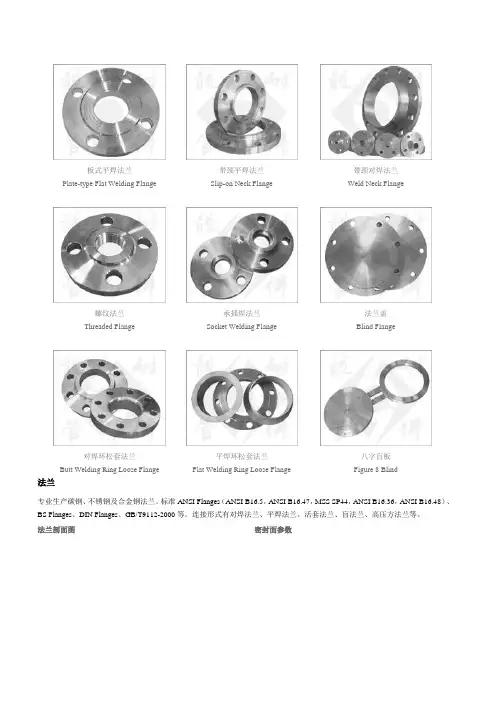
板式平焊法兰
带颈平焊法兰 带颈对焊法兰 Plate-type Flat Welding Flange
Slip-on Neck Flange
Weld Neck Flange
螺纹法兰 承插焊法兰 法兰盖 Threaded Flange
Socket Welding Flange
Blind Flange
对焊环松套法兰
平焊环松套法兰
八字盲板 Butt Welding Ring Loose Flange
Flat Welding Ring Loose Flange
Figure 8 Blind
法兰
专业生产碳钢、不锈钢及合金钢法兰。
标准ANSI Flanges (ANSI B16.5,ANSI B16.47,MSS SP44,ANSI B16.36,ANSI B16.48)、BS Flanges 、DIN Flanges 、GB/T9112-2000等。
连接形式有对焊法兰、平焊法兰、活套法兰、盲法兰、高压方法兰等。
法兰剖面图
密封面参数
法兰结构图
板式平焊法兰(PL)带颈平焊法兰(SO)带颈对焊法兰(WN)承插焊法兰(DN15-80)SW
螺纹法兰(DN15-80)TH法兰盖(BL)带颈对焊环松套法兰LF.SE平焊环松套法兰PJ.RJ
环槽面法兰及法兰盖大直径平板法兰(600-4800mm)大直径高颈法兰(600-4000mm)八字盲板BL
法兰制造标准
法兰常用材料。
ANSI-ASME B16.5 Flanges
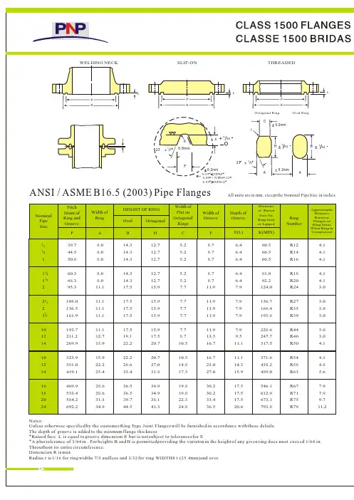
Notes:Unless otherwise specified by the customer.Ring Type Joint Tlanges will be furnished in accordance with these delails.The depth of groove is added to the minmum flange thickness*Raised face L is equal to groove dimension E but is not subject to tolerances for E*A plus tolerance of 3/64 in . For heights B and H is permitted providing the variaton in the height of any given ring does nnot exceed 1/64 in.Throuthout its entire circumference.Dimeneion R is maxRadius r is 1/16 for ring widths 7/8 and less and 3/32 for ring WIDTHS 1 (25.4mm)and over.39.744.550.860.368.395.3108.0136.5161.9193.7211.2269.9323.9381.0419.1469.9533.4584.2692.28.08.08.08.08.011.111.111.111.111.112.715.915.922.225.428.628.631.834.912.712.712.712.712.715.915.915.915.915.917.520.720.727.031.834.934.938.141.314.314.314.314.314.317.517.517.517.517.519.122.222.228.633.436.536.539.744.54.14.14.14.14.13.03.03.03.03.03.04.14.14.85.67.97.99.711.2R12R14R16R18R20R24R27R35R39R44R46R50R54R58R63R67R71R75R7960.560.560.581.092.2124.0136.7168.4193.8228.6247.7317.5371.6438.2489.0546.1612.9673.1793.86.46.46.46.46.47.97.97.97.97.99.511.111.114.315.917.517.517.520.68.78.78.78.78.711.911.911.911.911.913.516.716.723.027.030.230.233.436.55.25.25.25.25.27.77.77.77.77.78.710.510.514.817.319.819.822.324.812/34/11222311101214101214161820241//4211//22All units are in mm, except the Nominal Pipe Size in inches.ANSI / ASME B16.5 (2003) Pipe FlangesNominalPipe SizePitch Diam.of Ring and GrooveWidth of RingOval OctagonalWidth of Flat on Octagonal RingsWidth of GrooveDepth of Groove Ring NumberDiameter of Raised Face for Ring Joint or LappedPA B H C F E(L )K(MIN)Approximdte Distance Between Flanges of Ring Joints When Ring in CompressedHEIGHT OF RING P LLLKP KP KR0.8mm0.2mm23HCB AA0.2mm0.2mm116464E164+F231212rOctagonal Ring Oval Ring0.03 NPS5 0.06=N P S6-12 0.09NPS14WELDING NECK SLIP-ON THREADEDR=All units are in mm, except the Nominal Pipe Size in inches.Notes:Unless otherwise speciied by the customer . Ring Type Joint Flanges will be finished in accordance with these details.The depth of groove is added to the minimum f lange thickness*Raised face L is equal to groove dimension E but is not subject to tolerances for E *A plus tolerance of 3/64 in . Throuthout its entire circumference. Exceed1/64 in . Throuthout its entire circumference.Dimension R is max.Radius r 1/16for ring widths7/8and les and 3/32for ring widths 1 25.4mm and over42.950.860.3R13R16R18R21R23R26R28R32R38R42R47R51R55R604.14.14.13.03.03.03.03.04.14.14.14.86.47.965.073.282.6101.6114.3133.4149.4168.4203.2241.3279.4339.9425.5495.36.46.46.47.97.97.99.59.511.112.712.714.317.517.58.78.78.711.911.911.913.513.516.719.819.823.030.233.45.25.25.27.77.77.78.78.710.512.312.314.819.822.312.712.712.715.915.915.917.517.520.723.823.827.034.938.114.314.314.317.517.517.519.119.122.225.425.428.636.539.78.08.08.011.111.111.112.712.715.919.119.122.228.631.872.282.6101.6111.1127.0157.0190.5228.6279.4342.9406.41/23/41421/1/1125681012341/22ANSI / ASME B16.5 (2003) Pipe FlangesNominalPipe SizePitch Diam.of Ring and Groove Width of RingOval OctagonalWidth of Flat on Octagonal RingsWidth of Groove Depth of Groove Ring NumberDiameter of Raised Face for Ring Joint or LappedPA B H C F E(L)K(MIN)Approximdte Distance Between Flanges of Ring Joints When Ring is CompressedHEIGHT OF RINGP LLLKP KP KR0.8mm0.2mm23HCB AA0.2mm0.2mm116464E164+F231212rOctagonal Ring Oval Ring 0.03 NPS2 0.06=N P S21/2-8 0.09NPS10WELDING WEAK SLIP-ON THREADEDR=ANSI B16.5 (ASME B16.5: 2003) Pipe FlangesSTOCK FINSH The most widely used of any gasket finish, because practically.IS SUITABLE FOR ALL ORDINARY SERVICE CONDITIONSThis is a continuous spiral .Flanges sizes 12 (304.8mm)and smaller,are produced with a 1/16 round - nosedtool at a feed of 1/32 per revolution.For sixes 14 (355.6mm) and larger, the finisn is made with 1/8 round- nosed tool at a feed of 3/64 per revolution.SPIRAL SERRATED OR PHONOGRAPHIC:This finish is produced by using a 90 round - nosed tool.CONCENTRLC SERRATED :This finish a produced by using a 90 round-noise tool.SMOOTH FINISH:The cutting tool employed shall have an approximate 0.06 radius.The resultant surface finish shall have a 125 inch to 250 inch(ANSL B16.5 para 6.4;4.1)1RAISED FACE,AND LARGE MALE AND FEMALEEither a serrated - concentric or serratded-spiral finish having from 34 to 64 grooves per inch is ubed. The cutting tool employed has an approximate 0.06 in radous. The resultant surface finish shall have a 125 inch(3.2 m) to 500 inch(12.5 m) approximate roughness.2TONGUE AND GROOVE.AND SMALL MAKE AND FEMALEThe gasket contact surface does not edceed 125 in.(3.2 m) roughness.3RING JOINTThe inside wall surface of gasket groove does not exceed 63 in(1.6m) roughness.4BLINDBlind flanges need not be faced in the center if ,when this center part is raised, its diameter is at least in.Smaller than the inside diameter of fittings of the corresponding pressure class.When the center part is depressed, its diameter is not greater than the inside diameter of the corresponding pressure class fittings. Machining of the depressed center is not required.32411234118161.61332640.050.001970.80.060.00223.21.20.890Notes This tolerance is covared in ANSI B 16.5,but make soption20Outsied DiameterWhen O.D Is 24'' or Less When O.D Is Over 24 ''1/16''(1.6mm)1/8''(3.2mm)Inside DiameterThreadedWithin Limits on boring gauge Socket-Welding,Silp-on and Lap joint 10'' & Smaller +1/32''(0.8mm).,-0''12'' & Larger +11/16’'(1.6mm),-0Outside Diameter of Hub5'' and Smaller 6'' and Larger +3/32'' (2.4mm)-1/32''(0.8mm)+5/32'' (4.0mm)-1/32''(0.8mm)Diameter of Contact Face1/16'' Raised Face1/32''(0.8mm)1/4'' Raised Face Tongue & Groove Male. Female1/64''(0.4mm)DiameterofCounterboreSame as for Insied DiameterDrilingBolt Circle1/16''(1.6mm)Bolt Hole Spacing 1/32''(0.8mm)Eccentricity of Bolt Circle with Respect to Facing2 / 2''Smaller 1 / 32''(0.8mm) Max.3''& Larger1 / 16''(1.6mm) Max.1Eccentricity of Bolt Circle with Respect to Facing 1/32''(0.8mm) Max.Eccentricity of Facing with Respect to Bore 1/32''(0.8mm) Max.ThicknessLength Thru Hub18'' and Smaller20'' and Larger10'' and Smaller 12'' and Larger1/8'' (3.2mm). -0''3/16'' (4.8mm). -0''1/16'' (1.6mm)1/8'' (3.2mm)Outsied DiameterWhen O.D Is 24'' or Less When O.D Is Over 24 ''1/16''(1.6mm)1/8''(3.2mm)Inside Diameter10'' and Smaller1/32'' (0.8mm)12'' thru 18''1/16'' (1.6mm)Diameter of Contact FaceWhen Hub Base is 24'' or Smaller When Hub Base isOver 24''1/16''(1.6mm)1/8''(3.2mm)Diameter of Hub at Point of Welding5'' and Larger+3/32'' (2.4mm)-1/32'' (0.8mm)6'' and Larger +5/32'' (2.4mm)]-1/32'' (0.8mm)20'' and Larger+1/8'' (3.2mm)-1/16''(1.6mm)DrilingBolt Circle 1/16''(1.6mm)Bolt Hole Spacing1/32''(0.8mm)Eccentricity of Bolt Circle with Respect to Facing2 / 2''Smaller 1 / 32''(0.8mm) Max.3''& Larger1 / 16''(1.6mm) Max.1Eccentricity of Bolt Circle with Respect to Bore 1/32''(0.8mm) Max.Eccentricity of Facing with Respect to Bore 1/32''(0.8mm) Max.Thickness18'' and Smaller20'' and Larger10'' and Smaller12'' and Larger1/8'' (3.2mm). -0''3/16'' (4.8mm). -0''1/16'' (1.6mm)1/8'' (3.2mm)Length Thru HubAll units are in mm, except the Nominal Pipe Size in inches.td adDD DTDd d 1tt TO C f 3C F f 4341f f F C C C C 1234334SOLID FLANGE SILP-ON FLANGE WELDING NECK FLANGETYPE OF GSKET SUVF AVEMALK & FAMALE TYPE TONGUE & GROOVE TYPTAll units are in mm, except the Nominal Pipe Size in inches.RRWSXURWZU TY ZOS XKRANSI / ASME B16.5 (2003) Pipe FlangesNominal Pipe SizeOUTSIED DIAMETER Raised Face.L apped.L arge Male and Large TongueSmall Male Small TongueI.D.of Large and Small TongueOUTSIDE DIAMETERLarge Female and Large GrooveSmall Female Small GrooveI.D.of Large and GrooveHELGHTRaised Face and 300ST' DSRaised FaceLarge and Small Male and Tongue Classes 4002500ST' DSDepth of Groove or Female RS T U W L X Y Z 1/23/411/41/2111/233456810121416182024584.2692.2501.7603.3558.8666.8533.4641.4585.7693.7595.4703.335.142.950.863.573.291.938.144.557.268.384.196.8109.5136.7162.1212.9266.7317.5349.3400.1450.9157.2185.7215.9269.7323.9381.0412.8469.9533.418.323.930.235.142.947.857.263.582.695.3117.3130.0144.5173.0203.2254.0304.8362.0393.7447.5511.025.433.338.147.853.873.265.074.793.7106.4128.5141.2158.8187.5217.4271.5325.4382.5414.3471.4534.985.9108.0120.7131.8160.3190.5238.3285.8342.9374.7425.5489.036.644.552.346.053.862.074.784.1103.1115.8138.2150.9168.1196.9227.1280.9335.0392.2423.9481.1544.119.825.431.839.646.058.769.985.998.6111.3138.2163.6214.4268.2319.0350.8401.6452.4503.2604.836.644.549.358.765.084.196.8119.1131.8146.1174.8204.7255.5306.3363.5395.2449.3512.8560.3668.323.931.836.646.052.371.484.1106.4119.1130.0158.0189.0236.5284.2341.4373.1423.9487.4531.9639.81.51.51.5 6.46.46.46.46.46.46.46.46.46.46.46.46.46.46.46.46.46.46.46.44.84.84.84.84.84.84.84.84.84.84.84.84.84.84.84.84.84.84.84.81/222104.6127.0139.7 1.51.51.51.51.51.51.51.51.51.51.51.51.51.51.51.51.51.5All units are in mm, except the Nominal Pipe Size in inches.Notes:1)Small male and female faces are not appilcable to Slip-on Flange. 2)Large male and female faces are not applicable to Class 150 Flanges.3)For flanges of Class 150 and 300 where they are to be bolted to ANSI Class 125 and 250 Cast-Iron Flanges or requited with flat face,flat face can be made by removing raised face.* Tolerances are 0.03 (+0.8mm) for 0.06 (1.6mm) RF and0.02(+0.5mm)for 0.25 (6.35mm) RFLarge Male and Large TongueT1.6mm 6.35mm 6.35mm 6.35mm 4.8mm 6.35mm 4.8mm E4.8mm Thickness1.6mmRemovableO.D.of Raised FaceAll units are in mm, except the Nominal Pipe Size in inches.Notes:1) Bore (B)of flanges is shall be specified by the purchaser. 2) Class 75 flanges 0.06(1.6mm) raised face, which is included in Thickness (t) and Length through Hub T1262830262830786837887711.2762.0812.8863.6920.8971.61022.41079.51130.31181.11234.91289.11339.91390.71441.51492.31543.11600.2941100510571124117512261276134113921443149415491600167517263234363840424446485052545658603234363840424446485052545658607628138649149651034108411351186125113021353140314571508157516261676857.3908.1965.21016.01066.81117.61174.81225.61276.41327.21378.01428.81485.91536.71587.5704.9755.7806.5676.1726.9777.733.333.333.3647.7698.5800.1850.9850.9952.51003.31054.11104.91155.71206.51257.31308.11358.91409.71460.51511.335.135.136.638.138.139.642.944.546.047.847.849.350.852.355.6828.5879.3935.0985.81036.61087.41140.01190.81241.61293.91344.71397.01450.81501.61552.4749.3641.4692.2743.0635.0736.6787.4838.2889.0939.8990.61041.41143.01143.01193.81244.61295.41346.21397.01447.81498.6793.8844.6895.4964.2997.01047.81049.41149.41200.21251.01301.81352.61403.41454.21505.0685.858.762.065.0661.9712.7763.57.97.97.9723.9774.7825.5364044485240404448364044444848404444876.3927.1992.11042.91093.71144.51203.51254.31305.11355.91409.71460.51521.01571.81622.67.97.99.79.79.79.79.79.79.79.79.79.711.211.211.2814.3865.1918.9966.71017.51068.31119.11169.91220.71271.51322.31373.11423.91474.71525.569.973.285.988.991.995.3104.6108.0111.3115.8120.7125.5134.9138.2144.519.119.119.148.0350.0362.0670.0574.0577.0982.08105.01120.03134.28142.18180.15184.58195.56210.2019.119.122.422.422.422.422.522.522.522.522.522.522.422.528.429.0131.0135.05684.3735.1787.441.144.544.544.547.850.8647.7698.5749.3641.4692.2743.0635.0685.8736.6787.4838.2889.0939.8990.61041.41092.21143.01193.81244.61295.41346.21397.01447.81498.6793.8844.6895.4964.2997.01047.81098.61149.41200.21251.01301.81352.61403.41454.21505.0800.1850.9901.7952.51003.31054.11104.91155.71206.51257.31308.11358.91409.71460.51511.353.857.258.763.566.568.371.474.777.780.884.187.490.493.596.846.049.552.353.855.658.760.562.065.068.369.971.473.274.776.2839.7892.0944.6997.01049.31101.91152.71205.01257.31308.11360.41412.71465.31516.11570.088.995.3100.1814.3865.1915.9968.21019.01069.81120.61171.41222.21273.01323.81374.61425.41476.21527.0108.0110.2117.3124.0128.5133.4136.7144.5149.4153.9157.2162.1166.6174.8179.3661.9712.7763.59.79.79.7900.1957.31009.71069.81120.61171.41222.21284.21335.01385.81436.61492.31543.11611.41662.29.79.79.79.79.711.211.211.211.211.211.211.214.214.214.2744.5795.3846.136404448404440444852404448525660485222.422.422.48510311714015316820021024025026631030636741022.425.425.428.428.428.431.831.831.831.831.831.831.835.135.1596874165201241288349397485556621704816915102111391274140615961754Nominal Pipe SizeOutside Diam.DG X A BOREL ength Thru Hub Diam.Of Hub af Bevel Radius af Base of Hub BoltCircle Diam.Approximate Weight (Kg)9.5mm WithinNumber of HolesDiam.Of HolesWall Thckness6.35mm9.5mm B1T1A R C DRIL L ING12.7mmO.D.of Raised FaceDiam.At Base - HubThick-ness CLASS 150 FLANGESCLASS 75 FLANGESNominal PipeSizeOutsideDiam.DG X T (BL )BOREL ength Thru Hub Diam.Of Hub af Bevel Radius af Base of Hub BoltCircle Diam.Approximate Weight (Kg)9.5mm WithinNumberof Holes Diam.Of HolesWall Thckness6.35mm 9.5mm B1T1A R C W N DRIL L ING12.7mmO.D.ofRaisedFace Diam.At Base of HubThick-ness BL T 1371.6mm12ABT 1G X AB 1C Drt1161.6mm262830323436384042444648505254565860867921991105411081171122212731334138414611511156216131673176518271878736.6787.4844.6701.5755.7812.8665.2716.0768.4647.7698.5749.3641.4692.2743.0787.4838.2889.0939.8990.61041.41092.21143.01193.81244.61295.41346.21397.01447.81498.6793.8844.6895.4946.2997.01047.81098.61149.41200.21251.01301.81352.61403.41454.21505.0800.1850.9901.7952.51003.31054.11104.91155.71206.51254.31308.11358.91409.71460.51511.3819.2870.0920.8971.61022.41074.71125.51176.31277.11277.91328.71379.51422.41481.11531.9863.6917.4965.21016.01066.81117.61173.21228.851277.91330.51382.81435.11493.81547.91598.7901.7925.51009.71060.51114.61168.41219.21270.01327.21378.01428.81479.61536.71593.91651.0635.0736.6685.8144.5149.4158.0168.1173.0180.8192.0198.4204.7214.4222.3223.8235.0242.8239.8268.2274.6271.588.988.993.788.988.993.714.214.214.2803.1857.3920.832363635.135.138.133036041057166172180197199110481114116113361428145141.141.144.544.544.547.847.850.850.850.850.850.860.560.560.5323632364036403640444848364040977.91031.71089.21140.01190.81244.61295.41365.31416.11466.91517.71577.81651.01712.01763.815.715.715.715.715.715.715.715.715.715.715.715.717.517.517.5103.1103.1103.1103.1103.1103.1111.3115.8119.1111.3115.8119.1127.0128.5128.5138.2142.7136.7153.9153.9150.9127.0130.0134.9139.7144.3149.4157.0162.1166.620027021067774783898311101256144116491829202122232486291332183504393540443Notes:(1)Bors (B)of flanges is shall be specified bu the purchaser(2) Class 300 flanges will be furnished will be furnished 0.06 (1.6mm) raised face,which is included in Thickness (t) and Length through Hub T1All units are in mm, except the Nominal Pipe Size in inches.ANSI / ASME B16.5 ( 2003) Pipe FlangesNominal Pipe Size Outside Diam.DGXTBOREL engthThruHubThicknessRadius af Base of Hub Bolt Circle Diam.Approximate Weight (Kg)9.5mm Within Number of Holes Diam.Of HolesWall Thckness 6.35mm 9.5mm B1T1T(BL )RCBLDRIL L ING 12.7mmO.D.of Raised Face Diam.At Base of Hub Thick-ness W NB1.6mmA3712/T 1XAB 1T 1G C tDrDetail wTypical Welding end Preparation1/161.6mmSee Detail wNominal Pipe SizeOutside Diam.D O.D.ofRaised FaceG DiamAt Base Of Hub X Thickness t BoreWall Thickness9.5mm12.7mmB1Length Thru Hub T1Diam.of Hub af Bevel A Radius af Base of Hub r DrillingBolt Circle Diam.C Number of Holes Diam.Of Holes Approximate Weight (kg)WNBL121416182022483533597635699749381.0412.8469.9533.4584.2641.4365.3400.1457.2505.0558.8609.631.835.136.639.642.946.0304.8336.6387.4438.2489.0539.8298.5330.2381.0431.8482.6533.4114.3127.0127.0139.7144.5149.4323.9355.6406.4457.2508.0558.89.79.79.79.79.79.7431.8476.3539.8577.9635.0692.212121616202025.428.428.431.831.835.1____________24262830323436384042444648505254565860813870927984106011111168123812891346140310541511156816281683174618031854692.2749.3800.1857.3914.4965.21022.41073.21124.01193.81244.61295.41358.91409.71460.51511.31574.81625.61676.4663.4676.1726.9781.1831.9882.7933.5990.61041.41092.21143.01196.81247.61301.81352.61403.41457.51508.31559.147.868.371.474.780.882.690.487.490.496.8101.6103.1108.0111.3115.8120.7124.0128.5131.8590.6641.4692.2743.0793.8844.6895.4946.2997.01047.81098.61149.41200.21251.01301.81352.61430.41454.21505.0584.2635.0685.8736.6787.4838.2889.0939.8990.61041.41092.21143.01193.81244.61295.41346.21397.01447.81498.6152.4120.7125.5136.7144.5149.4157.0157.2163.6171.5177.8185.7192.0203.2209.6215.9228.6235.0239.8609.69.79.711.211.211.212.711.711.712.712.712.712.712.712.712.712.712.712.712.7749.3806.5863.6914.4977.91028.71085.91149.41200.21257.31314.51365.31422.41479.61536.71593.91651.01708.21759.020242828283232323644444435.135.135.135.141.141.141.141.141.141.141.141.141.147.847.847.847.847.847.8__147165193243258193243258306342368422470503556598661936306363430537600730794893104411901299147016161817203122442491269744484852T o b e s p e c i f i e d b y p u r c h a s e r364040MSS SP44 FORGED FLANGESAll units are in mm, except the Nominal Pipe Size in inches.D CGB 10.061.6mmt 1t 2T 1rA XNominal Pipe SizeOutside Diam.D O.D.of Raised Face G DiamAt BaseOf HubX Thicknesst1BoreWall Thickness9.5mm12.7mmB1Length Thru Hub T1Diam.of Hub of Bevel A Radius of Fillet r DrillingBolt Circle Diam.C Number of Holes Diam.Of Holes Approximate Weight (kg)WNBL121416182022521584648711775838381.0412.8469.9533.4584.2641.4374.7425.5482.6533.4587.2641.450.853.857.260.563.566.5304.8336.6387.4468.2489.0539.8298.5330.2381.0431.8482.6533.4130.0142.7146.1158.8162.1165.1323.9355.6406.4457.2508.0558.89.79.79.79.79.79.7450.9514.4571.5628.7685.8743.016202024242431.831.835.135.135.141.1____________2426283032343638404244464850525456586091497210351092114912071270116812381289135314161467153015811657170817591810692.2749.3800.1857.3914.4965.21022.41028.71085.91136.71193.81244.61301.81358.91409.71466.91517.71574.8625.6701.5720.9774.7827.0881.1936.8990.6993.61047.81098.61149.41203.51254.31305.11355.91409.71463.51514.31565.169.979.285.991.998.6101.6104.6108.0114.3119.1124.0128.5133.4139.7144.5152.4153.9158.8163.6590.6641.4692.2743.0793.8844.6895.4946.2997.01047.81198.61149.41200.21251.01301.81352.61403.41454.21505.0584.2635.0685.8736.6787.4838.2889.0939.8990.61041.41092.21143.01193.81244.61295.41346.21397.01447.81498.6168.1184.2196.9209.6222.3231.6241.3180.8193.5200.2206.2215.9223.8231.6238.3252.5260.4266.7273.1609.69.79.711.211.211.212.712.712.712.712.712.712.712.712.712.712.712.712.712.7812.8876.3939.8997.01054.11104.91168.41092.21155.71206.51263.71320.81371.61428.81479.61549.41600.21651.01701.824282828282832323232323241.144.544.547.850.850.853.841.144.544.547.850.850.853.853.860.560.560.560.5__27534038944549856330739240946454456964569483488292898946056666377089410408721035117313401600170019362143248626742913318432322828283232T o b e s p e c i f i e d b y p u r c h a s e rWelding NeckBlindt250.853.857.260.563.566.569.984.190.4660.4711.2762.0812.8863.695.3100.1104.6111.3108.0114.3914.4119.1124.0128.5133.4139.7144.5152.4153.9158.8163.6MSS SP44 Forged FlangesAll units are in mm, except the Nominal Pipe Size in inches.D Ct 2EK PB 1Et 1T 1A XrR EF23D CGB 1A Xrt 20.06,,1.6mmt 1T 127Nominal Pipe Size Outside Diam.D O.D.of Raised Face G Diam At Base Of Hub XThickness t 1Bore Wall Thickness 9.5mm 12.7mm B 1Length Thru Hub T 1Diam.Thru Hub A Radius of Base of Hub r Drilling Bolt Circle Diam.C Number of Holes Diam.Of Holes Approximate Weight (kg)WN BL 121416182022558.8602.0685.8743.0812.8870.0381.0412.8469.9533.4584.2641.4400.1431.8495.3546.1609.6666.866.569.976.266.569.976.282.688.995.3304.8336.6387.4438.2488.9539.8298.5330.2381.0431.8482.6533.4155.4165.1177.8184.2190.5196.9323.9355.6406.4457.2508.0558.811.211.211.211.211.211.2498.0527.1603.3654.1723.9777.720202020242435.138.141.144.544.547.8____________24262830323436384042444648505254565860939.81016.01073.21130.31193.81244.61314.51270.01320.81403.41454.21511.31593.91670.0120.91778.01854.21905.01993.9692.2749.3800.1857.3914.4965.21022.41054.1111.31168.41225.61276.41333.51384.31435.11492.31543.11600.21657.4717.6747.8803.2826.1917.5973.11031.81022.41073.21127.31181.11235.01289.11343.21394.01447.81501.71552.51609.9101.6108.0111.3114.3117.4120.7124.0152.4158.8168.2173.0179.3189.0196.9203.2209.6217.4222.3233.4590.6641.4692.2743.0793.8844.6895.4946.2997.01047.81098.61149.41200.21251.11301.81352.61403.41454.21505.0584.2635.0685.8736.6787.4838.2889.0939.8990.61041.41092.21143.01193.81244.61295.41346.21397.01447.81498.6203.2222.25234.95247.65260.35269.75282.45254.00263.65279.40289.05299.97315.98328.68336.55349.25361.95369.82388.87609.611.212.712.712.712.714.214.214.214.214.214.214.214.214.214.214.215.815.817.5838.2914.4965.21022.41079.51130.31193.81162.11212.91282.71333.51390.71460.51524.11574.81632.01695.51746.31822.524282828282828283232283250.850.853.853.860.560.566.560.560.566.566.566.573.279.279.279.285.985.991.9__43148455061467576464569385891110191200140314731616182019292325765896106012371410164514921676200622232518292533513650405945504950570928323232323228T o s p e c i f i e d b y p u r c h a s e r Welding Neck Blind t 282.688.995.3101.6125.5131.8660.4711.2762.0812.8863.6139.7147.6153.6162.1155.5162.1914.4171.5177.8185.7195.3203.2209.6217.4225.6231.7242.8All units are in mm, except the Nominal Pipe Size in inches.MSS SP44 Forged FlangesDD C CK P t 2t 1T 1EEEB 1AX r G B 1 6.35mm t 1t 2E F T 1r A X23NominalPipeSizeOutside Diam.D Bore B Thickness Class B(t)Class D(t)DRILLING Bolt Circle Diam.C 78911141718212225272931343638404245474951535658606269768289951021081141206868727252606464444444523640404432323236242828281620202012121216888811111111111111111111111111222222221261327676Number of Holes Diam.of Bolt Holes Class D(t)Class B(t)2845681012141618202224262830323436384042444648505254606672788490961021081141209101113 4.575.666.728.7210.8812.8814.1916.1918.1920.1922.1924.1926.1928.1930.1932.1934.1936.1938.1940.1942.1944.1946.1948.1950.1952.1954.1960.1966.1972.1978.1984.1990.1996.19102.19108.1916192123252729323436384143464850535557596164667380869399106113120126133140114.19120.191/21/21/21/214/12/34/34/34/34/34/14/14/12/34/14/12/34/12/14/34/12/14/5/85/811/1611/1611/1611/1611/1611/1611/1611/163/43/413/167/87/815/1615/1611111111/81/81/81/411111/41/43/81/211225/83/422221/41/41/21/2223/43/4331/21/233331/41/422221/25/83/43/422221/41/811113/43/43/43/411111/25/85/85/811115/165/163/81/211111/161/813/161/411/1613/1615/1615/85/811/1611/161/21/21/23/41/43/41/43/41/41/23/41/21/23/41/41/41/23/43/41/41/23/41/41/21/21/21/23/43/43/43/43/43/43/43/43/47/87/87/87/87/87/87/87/811111111111/81/81/81/811111/41/43/83/811113/83/85/85/811227/87/81/81/8223/83/87/87/85/85/83/83/81/81/87/87/87/87/87/87/85/85/85/85/85/85/85/85/85/83/83/83/83/83/81/41/41/81/87/87/87/83/4AWWA Standard Steel Ring Flanges, Class B(86 psi) and Class D (175-150psi)All units are in mm, except the Nominal Pipe Size in inches.tD C t DCBAll units are in mm, except the Nominal Pipe Size in inches.2945688121212161620202024282828323232363640404444444452526064646868727276768881012141618202224262830323436384042444648505254606672788490961021081141209101113 4.575.666.728.7210.8812.8814.1916.1918.1920.1922.1924.1926.1928.1930.1932.1934.1936.1938.1940.1942.1944.1946.1948.1950.1952.1954.1960.1966.1972.1978.1984.1990.1996.19102.19108.19114.19120.19161921232527293234363841434648505355575961646673808393991061131201261331401/21/21/21/21/41/23/43/43/43/43/41/41/41/23/41/41/23/41/21/43/41/21/41/2/99/16169/1611/16/11163/43/43/43/4111/811111/811111/81/81/811113/81/41/41/411111/23/83/83/811113/43/41/21/222221/41/4221/21/21/41111/41/47/81/41111/41/41/411415183/43/812//11166799/165165/1651113/43/41/41/411113/43/43/43/411113/43/43/43/412221/21/41/43/412223/41/21/21/222333/43/423331/41/4333/43/431/21/2222426191/81/47/8303234283/41/21/21/23840433647495145555763533/43/43/4758187691/21/4100 931051111/23/41171243/43/4891111//2271/23/41718211/4143/41/4828995761/26062691/4583/41/45153561/2493/43/44245471/2401/41/43436383/4311/22527293/4221/41/23/41/21/2108 1021141203/41/21/21261323/43/43/43/43/43/43/47/87/87/83/43/47/87/87/87/87/87/87/87/811111111111/81/81/81/811111/41/43/83/811113/83/85/85/8117/87/8221/81/8223/83/81/81/811113/83/811111/41/43/85/811113/83/85/85/811115/85/85/85/811115/85/85/85/8227/87/822223/83/81/81/822117/87/87/87/811117/87/8Notes:(1)For Slip-on Flanges ,(Hub Type Flanges),the hubs can be shaped either vertical from base to top or tapered within the limits of 7 degrees.(2) The Bore (B) shall be 3/rger than the nominal outside diameter of the pipe,umless otherwise specifiedAWWA Standard Steel Hub Flanges, Class B(86 psi) and Class D (175-150psi)Nominal Pipe Size OutsideDiam.D Bore B Thickness t T X 1/L ength ThroughHub Diam of Hub at Base C Bolt CircleDiam Numberof Holes DRILLING Diam.of Bolt HolesClass B Class DDCXBt。
ansi b16.5法兰标准

ANSI B16.5法兰标准简介ANSI B16.5是美国国家标准制定机构ANSI(美国国家标准学会)制定的一项用于管道连接的标准,也称为ASME B16.5。
该标准规定了管道法兰以及相关附件(如螺栓、垫片等)的尺寸、材料要求和安装方法。
ANSI B16.5法兰标准被广泛应用于各种工业领域,包括石油化工、能源、造船、水处理等。
标准内容ANSI B16.5标准主要包括以下几个方面的内容:法兰尺寸ANSI B16.5标准规定了各种类型的法兰的尺寸范围,包括公称管径、法兰厚度、法兰外径等。
根据不同的应用需求,可以选择适当的法兰尺寸进行使用。
法兰材料根据应用环境和工作条件的不同,ANSI B16.5标准规定了一系列适用于法兰制造的材料,包括常见的碳钢、不锈钢、合金钢等。
这些材料的选择应根据工作温度、压力和介质特性进行考虑。
ANSI B16.5标准定义了多种类型的法兰,包括焊接颈法兰、螺纹法兰、盲板法兰、滑动法兰等。
每种类型的法兰都有不同的特点和适用范围,使用者可以根据需要选择合适的法兰类型。
法兰连接方式ANSI B16.5标准规定了法兰连接的安装方法,例如焊接、螺栓紧固、预紧连接等。
这些连接方式的选择应根据管道系统的需求和使用要求来确定。
法兰密封ANSI B16.5标准规定了法兰及其附件之间的密封要求,包括垫片的材料、厚度和安装方法等。
合理选择和正确安装垫片可以保证法兰连接的密封性能。
应用领域ANSI B16.5法兰标准广泛应用于各种工业领域,包括以下几个方面:石油化工行业石油化工行业是ANSI B16.5法兰标准的主要应用领域之一。
在炼油、化工生产过程中,需要进行各种管道连接,如管道与设备的连接、管道与管道的连接等。
ANSI B16.5标准规定了符合工业安全和环境要求的管道连接尺寸和材料,保证了工艺流程的正常进行。
能源行业包括发电、输电和供热等领域,这些领域都需要大量的管道连接。
ANSI B16.5标准被广泛应用于能源行业的管道系统中,确保能源的传输和利用过程安全可靠。
ASME-ANSI标准法兰尺寸
❍ Materials. Most standards specify the material ❍ Face Finish. The finish on the face of a flange is
Flange Types
:HOG 1HFN
This flange is circumferentially welded into the system at its neck which means that the integrity of the butt welded area can be easily examined by radiography. The bores of both pipe and flange match, which reduces turbulence and erosion inside the pipeline. The weld neck is therefore favoured in critical applications
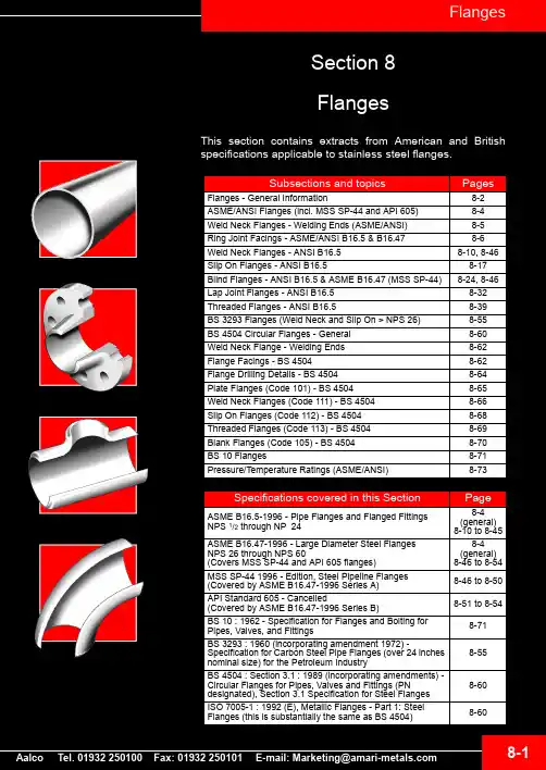
8-1
Flanges
Flanges - General Information
A Flange is a method of connecting pipes, valves, pumps and other equipment to form a pipework system. It also provides easy access for cleaning, inspection or modification. Flanges are usually welded or screwed into such systems and then joined with bolts.
ASME B16.47 Series B
ANSIB165《钢制管法兰及法兰管件》
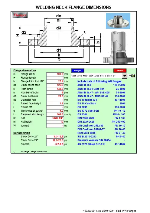
1903236611.xls 2019/12/11 blad WN Flanges
1903236611.xls 2019/12/11 blad WN Flanges
1903236611.xls 2019/12/11 blad WN Flanges
1903236611.xls 2019/12/11 blad WN Flanges
1903236611.xls 2019/12/11 blad WN Flanges
1903236611.xls 2019/12/11 blad WN Flanges
1903236611.xls 2019/12/11 blad WN Flanges
1903236611.xls 2019/12/11 blad WN Flanges
25-800#
8 pce
ANSI B 16.47 - API Std. 605
75-900#
22.3 mm
ANSI B 16.47 - MSS SP-44 150-900#
- mm
BS 10 tables A-T
43-1400#
1.6 mm
BS 10 Cast iron
200#
- mm
BS 3293
43-1400#
1)
for flange / flange connection
1903236611.xls 2019/12/11 blad WN Flanges
1903236611.xls 2019/12/11 blad WN Flanges
1903236611.xls 2019/12/11 blad WN Flanges
1903236611.xls 2019/12/11 blad WN Flanges
ASME B16.5 报告模板
TEST REPORTASME B16.5Pipe Flanges and Flanged FittingsReport reference No. ........................ :TCF-GBH-8957Tested by (+ signature) .................. :Kevin Yang ................................................... Approved by (+ signature) ............. :King Hu ................................................... Date of issue ..................................... :November 19, 2018Testing laboratory ............................. :Address ............................................ :Applicant ........................................... :Qingdao Fert Industrial Co.,Ltd.Address ............................................ :No. 100 Hong Kong Middle Road, Qingdao, ChinaManufacturer .................................... :Same as applicantAddress ............................................ :Factory .............................................. :Same as manufacturerAddress ............................................ :Standard ........................................... :ASME B16.5-2017Test Report Form No. ....................... :Master TRF ....................................... :Dated 06-06Test procedure ................................ :Commission testProcedure deviation .......................... :N/ANon-standard test method ................ :N/AType of test object ............................ :See Page 3Trademark ........................................ :-Model/type reference ........................ :See Page 3Rating ............................................... :-VersionType of test object and model / type reference check listAnnex I: Photo documentationType of equipment, model: Carbon Steel Elbow01 Carbon Steel Elbow (Carbon Steel Lr 90 Elbow Sch40 A234 WPB Black Lacquer)Details of: Model 3", 6", 10", 2-1/2", 3", 1-1/2", 1/2", 3/4", 1", 1-1/2", 2", 3", 4" ,6"View:[X] general[ ] front[ ] rear[ ] right[ ] left[ ] top[ ] bottomDetails of: Model 3", 6", 10", 2-1/2", 3", 1-1/2", 1/2", 3/4", 1", 1-1/2", 2", 3", 4" ,6"View:[X] general[ ] front[ ] rear[ ] right[ ] left[ ] top[ ] bottomDetails of: Carbon Steel Tee (Carbon Steel Tee Sch 40 A234 WPB Black Lacquer), 1", 1-1/4", 1-1/2", 2-1/2", 3", 4", 6", 8", 10"4"*2", 4"*2-1/2", 4"*3", 6"*3", 6"*4", 8"*4", 8"*6", 10"*6", 10”*8“View: [X] general [ ] front [ ] rear [ ] right [ ] left [ ] top [ ] bottomDetails of: Carbon Steel Con Reducer(Carbon Steel Con Reducer SCH 80 A234 Wpb Black Lacquer) Model 1-1/2"*1-1/4", 4"*2-1/2", 3/4"*1/2", 1"*1/2", 1"*3/4", 2"*1", 2"*1-1/2", 3"*1-1/2", 3"*2", 3"*2-1/2", 4"*2", 4"*3", 6"*3", 6"*4"View: [X] general [ ] front [ ] rear [ ] right [ ] left [ ] top [ ] bottomType of equipment, model: Carbon Steel Flange So (Carbon Steel Flange So(Class 150)-Q235 BlackLacquer), model 1”, 1-1/2", 2", 3", 4", 6", 8", 10", 1", 1-1/4", 1-1/2", 2", 2-1/2",3", 4", 6"Details of: model 1”, 1-1/2", 2", 3", 4", 6", 8", 10", 1", 1-1/4", 1-1/2", 2", 2-1/2", 3", 4", 6"View:[X] general[ ] front[ ] rear[ ] right[ ] left[ ] top[ ] bottomType of equipment, model: Carbon Steel Flange Blind(Class 150)-Q235 Black Lacquer), model 1-1/2",2", 3", 4", 6", 8", 1", 1-1/4", 1-1/2", 2", 2-1/2", 3", 4", 6"Details of: model 1-1/2", 2", 3", 4", 6", 8", 1", 1-1/4", 1-1/2", 2", 2-1/2", 3", 4", 6"View:[X] general[ ] front[ ] rear[ ] right[ ] left[ ] top[ ] bottomDetails of: model 1-1/2", 2", 3", 4", 6", 8", 1", 1-1/4", 1-1/2", 2", 2-1/2", 3", 4", 6" View:[X] general[ ] front[ ] rear[ ] right[ ] left[ ] top[ ] bottom- End of Test Report -。
ANSI标准法兰详细概述
DevilBridas Blind / Blind Flanges 150 Lb. Ver imagen ANSI 20 - See ANSI image 20 ASME B 16.5 - a - 1998 Resalte Raised face g mm. inches 34,9 1 3/8 42,9 1 11/16 50,8 2 63,5 2 1/2 73 2 7/8 92,1 3 5/8 104,8 4 1/8 127 5 139,7 5 1/2 157,2 6 3/16 185,7 7 5/16 215,9 8 1/2 269,9 10 5/8 323,8 12 3/4 381 15 412,7 16 1/4 469,9 18 1/2 533,4 21 584,2 23 641,2 25 1/4 692,1 27 1/4 Peso aprox. Approx. Weight Kg. Pounds 0,5 1 0,9 2 0,9 2 1,4 3 1,8 4 2,3 5 3,2 7 4,1 9 5,9 13 7,7 17 9,1 20 11,8 26 21 46.2 31,8 70 49,9 110 63,5 140 81,6 180 99,8 220 129 285 161 355 195 c 430Diámetro nominal Nominal pipe sizeBrida FlangeTaladros Drilling templateD mm. inches 88,9 3 1/2 98,4 3 7/8 108 4 1/4 117,5 4 5/8 127 5 152,4 6 177,8 7 190,5 7 1/2 215,9 8 1/2 228,6 9 254 10 279,4 11 342,9 13 1/2 406,4 16 482,6 19 533,4 21 596,9 23 1/2 635 25 698,5 27 1/2 749,3 29 1/2 812,8 32b mm. inches 11,1 7/16 12,7 1/2 14,3 9/16 15,9 5/8 17,5 11/16 19,1 3/4 22,2 7/8 23,8 15/16 23,8 15/16 23,8 15/16 23,8 15/16 25,4 1 28,6 1 1/8 30,2 1 3/16 31,8 1 1/4 34,9 1 3/8 36,5 1 7/16 39,7 1 9/16 42,9 1 11/16 46 1 13/16 47,6 1 7/8Numero Number 4 4 4 4 4 4 4 4 8 8 8 8 8 12 12 12 16 16 20 20 20I mm. inches 15,9 5/8 15,9 5/8 15,9 5/8 15,9 5/8 15,9 5/8 19 3/4 19 3/4 19 3/4 19 3/4 19 3/4 22,2 7/8 22,2 7/8 22,2 7/8 25,4 1 25,4 1 28,6 1 1/8 28,6 1 1/8 31,7 1 1/4 31,7 1 1/4 34,9 1 3/8 34,9 1 3/8K mm. inches 60,3 2 3/8 69,8 2 3/4 79,4 3 1/8 88,9 3 1/2 98,4 3 7/8 120,6 4 3/4 139,7 5 1/2 152,4 6 177,8 7 190,5 7 1/2 215,9 8 1/2 241,3 9 1/2 298,4 11 3/4 361,9 14 1/4 431,8 17 476,2 18 3/4 539,7 21 1/4 577,8 22 3/4 635 25 692,1 27 1/4 749,3 29 1/21/2" 3/4" 1" 1 1/4" 1 1/2" 2" 2 1/2" 3" 3 1/2" 4" 5" 6" 8" 10" 12" 14" 16" 18" 20" 22" 24"BRIDAS BLIND BLIND FLANGES 150, 300 LB.Imagen 20Bridas lap joint / Lap joint flanges 150 Lb. Ver imagen ANSI 19 - See ANSI image 19 ASME B 16.5 - a - 1998Diámetro nominal Nominal pipe sizeBrida FlangeCuello HubTaladros Drilling templatePeso aprox. Approx. WeightD mm. inches 88,9 3 1/2 98,4 3 7/8 107,9 4 1/4 117,5 4 5/8 127 5 152,4 6 177,8 7 190,5 7 1/2 215,9 8 1/2 228,6 9 254 10 279,4 11 342,9 13 1/2 406,4 16 482,6 19 533,4 21 596,9 23 1/2 635 25 698,5 27 1/2 749,3 29 1/2 812,8 32J mm. inches 22,9 0.90 28,2 1.11 35,05 1.38 43,7 1.72 50 1.97 62,5 2.46 75,4 2.97 91,4 3.60 104,1 4.10 116,8 4.60 144,5 5.69 171,45 6.75 222,25 8.75 277,4 10.92 328,2 12.92 360,2 14.18 411,2 16.19 462,3 18.20 514,35 20.25 565,2 22.25 615,95 24.25b mm. inches 11,1 7/16 12,7 1/2 14,3 9/16 15,9 5/8 17,5 11/16 19,1 3/4 22,2 7/8 23,8 15/16 23,8 15/16 23,8 15/16 23,8 15/16 25,4 1 28,6 1 1/8 30,2 31,8 1 1/4 34,9 1 3/8 36,5 1 7/16 39,7 42,9 1 11/I6 46 1 13/16 47,6 1 7/8h mm. inches 15,9 5/8 15,9 5/8 17,5 11/16 20,6 13/16 22,2 7/8 25,4 1 28,6 1 1/8 30,2 1 3/16 31,7 1 1/4 33,3 1 5/16 36,5 1 7/16 39,7 1 9/16 44,4 1 3/4 49,2 55,6 2 3/16 79,4 3 1/8 87,3 3 7/16 96,8 103,2 4 1/16 108 4 1/4 111,1 4 3/8r mm. inches 3,2 1/8 3,2 1/8 3,2 1/8 4,8 5/16 6,35 1/4 7,9 5/16 7,9 5/16 9,5 3/8 9,5 3/8 11,1 7/16 11,1 7/16 12,7 1/2 12,7 1/2 12,7 1/2 12,7 1/2 12,7 1/2 12,7 1/2 12,7 1/2 12,7 1/2 12,7 1/2 12,7 1/2m mm. inches 30,2 1 3/16 38,1 1 1/2 49,2 1 15/16 58,7 2 5/16 65,1 2 9/16 77,8 3 1/16 90,5 3 9/16 107,9 4 1/4 122,2 4 13/16 134,9 5 5/16 163,5 6 7/16 192,1 7 9/16 246,1 9 11/16 304,8 12 365,1 14 3/8 400 15 3/4 457,2 18 504,8 19 7/8 558,8 22 616 24 1/4 663,6 26 1/8 4 4 4 4 4 4 4 4 8 8 8 8 8 12 12 12 16 16 20 20 20 NumeroI mm. inches 15,9 5/8 15,9 5/8 15,9 5/8 15,9 5/8 15,9 5/8 19 3/4 19 3/4 19 3/4 19 3/4 19 3/4 22,2 7/8 22,2 7/8 22,2 7/8 25,4 1 25,4 1 28,6 1 1/8 28,6 1 1/8 31,7 1 1/4 31,7 1 1/4 34.9 1 3/8 34,9 1 3/8K mm. inches 60,3 2 3/8 69,8 2 3/4 79,4 3 1/8 88,9 3 1/2 98,4 3 7/8 120,6 4 3/4 139,7 5 1/2 152,4 6 177,8 7 190,5 7 1/2 215,9 8 1/2 241,3 9 1/2 298,4 11 3/4 361,9 14 1/4 431,8 17 476,2 18 3/4 539,7 21 3/4 577,8 22 3/4 635 25 692,1 27 1/4 749,3 29 1/2 Kg. Pounds 0,5 1 0,9 2 0,9 2 1,4 3 1,4 3 2,3 5 3,2 7 3,6 8 5 11 5,9 13 6,8 15 8,6 19 13,6 30 19,5 43 29 64 47,6 105 63,5 140 72,6 160 88,5 195 111,2 245 125 2751/2" 3/4" 1" 1 1/4" 1 1/2" 2" 2 1/2" 3" 3 1/2" 4" 5" 6" 8" 10" 12" 14" 16" 18" 20" 22" 24"1 3/16 1 15/161 9/16 3 13/16BRIDAS LAP JOINT LAP JOINT FLANGES 150, 300, 400, 600, 900, 1500 y 2500 LB.Imagen 19Bridas long welding neck / Long welding neck flanges 150 lb. Ver imagen ANSI 26 - See ANSI image 26 ASME B 16.5 - a - 1998DIMENSIONES / DIMENSIONS Nominal pipe size Ø nominal Approx. Weight peso aprox. Pounds Kgs. Nº of holes Nº de taladrosD b h m J g I k inche inche inche inche inche inche inche inche s s s s s s s s mm. mm. mm. mm. mm. mm. mm. mm. 4.25 107,9 4.62 117,5 5.00 127 6.00 152,4 7.00 177,8 7.50 190,5 8.50 215,9 9.00 228,6 10.00 254 11.00 279,4 13.50 342,9 16.00 406,4 19.00 482,6 21.00 533,4 23.50 596,9 25.00 635 27.50 698,5 32.00 812,8 0.36 14,3 0.62 15,9 0.75 17,5 0.88 19,1 0.94 22,2 0.94 23,8 0.94 23,8 0.94 23,8 0.94 23,8 1.00 25,4 1.12 28,6 1.19 30,2 1.25 31,8 1.38 34,9 1.44 36,5 1.56 39,7 1.69 42,9 1.88 47,6 9 228,6 9 228,6 9 228,6 9 228,6 9 228,6 9 9 12 12 12 12 12 12 12 12 12 304,8 12 12 2.00 50,8 2.38 60,3 2.62 66.7 3.25 82,5 3.75 95,2 4.25 4.88 5.50 6.50 7.75 9.75 1.00 25,4 1.25 31,7 1.50 38,1 2.00 50,8 2.50 63,5 3.00 76,2 3.50 88,9 4.00 5.00 127 6.00 8.00 2.00 50,8 2.50 63,5 2.88 73 3.62 92,1 4.12 104,8 5.00 127 5.50 139,7 6.19 7.31 185,7 2.50 10.62 0.62 15,9 0.62 15,9 0.62 15,9 0.75 19 0.75 19 0.75 19 0.75 19 0.75 19 0.82 22,2 0.88 22,2 0.88 22,2 1.00 25,4 1.00 25,4 1.12 28,6 1.12 28,6 1.25 31,7 1.25 31,7 1.38 34,9 3.12 79,4 3.50 88,9 3.88 98,4 4.75 120,6 5.50 139,7 6.00 152,4 7.00 177,8 7.50 190,5 8.50 215,9 9.50 241,3 11.75 298,4 14.25 361,9 17.00 431,8 18.75 476,2 21.25 535,7 22.75 577,8 25.00 635 29.50 749,31" 1 1/4" 1 1/2" 2" 2 1/2" 3" 3 1/2" 4" 5" 6" 8" 10" 12" 14" 16" 18" 20" 24"8 3,6 10 4,5 12 5,5 16 7,3 21 9,5 24 11 31 14 47 21 57 26 77 35 103 47 150 68 215 98 221 100 254 115 278 126 324 147 439 2004 4 4 4 4 4 8 8 8 8 8 12 12 12 16 16 20 20228,6 107,9 228,6 123,8304,8 139,7 101,6 157,2 304,8 165,1304,8 196,8 152,4 215,9 304,8 247,6 203,2 269,9 12.00 10.00 12.75 254 323,8 381 14.38 12.00 15.00 16.00 14.00 16.25 18.00 16.00 18.50 20.00 18.00 21.00 508 457,2 533,4 508 584,2 22.00 20.00 23.00 26.25 24.00 27.25 304,8 304,8304,8 365,1 304,8304,8 406,4 355,6 412,7 304,8 457,2 406,4 469,9304,8 558,8304,8 666,7 609,6 692,1Espesor, taladro y caras de bridas según ASME B16.5 Flange, thickness, drilling and facings conforming to ASME B16.5BRIDAS LONG WELDING NECK LONG WELDING NECK FLANGES 150, 300 LB.Imagen 26Bridas Slip-on Slip-on Flanges 150 Lb. Ver imagen ANSI 17 - See ANSI image 17 ASME B 16.5 - a - 1998Diámetro nominal Nominal pipe sizeBrida FlangeCuello HubResalte Raised faceTaladros Drilling templatePeso aprox. Approx. WeightD mm. inches 88,9 3 1/2 98,4 3 7/8 107,9 4 1/4 117,5 4 5/8 127 5 152,4 6 177,8 7 190,5 7 1/2 215,9 8 1/2 228,6 9 254 10 279,4 11 342,9 13 1/2 406,4 16 482,6 19 533,4 21 596,9 23 1/2 635 25 698,5 27 1/2 749,3 29 1/2 812,8 32J mm. inches 22,3 0.88 27,7 1.09 34,5 1.36 43,2 1.70 49,5 1.95 62 2.44 74,7 2.94 90,7 3.57 103,4 4.07 116,1 4.57 143,8 5.66 170,7 6.72 221,5 8.72 276,35 10.88 327,15 12.88 359,15 14.14 410,5 16.16 461,8 18.18 513,1 20.20 564,4 22.22 615,95 24.25b mm. inches 11,1 9/16 12,7 1/2 14,3 9/16 15,9 5/8 17,5 11/16 19,1 3/4 22,2 7/8 23,8 15/16 23,8 15/16 23,8 15/16 23,8 15/16 25,4 1 28,6 1 1/8 30,2 31,8 1 1/4 34,9 1 3/8 36,5 1 7/16 39,7 42,9 1 11/16 46 1 13/16 47,6 1 7/8h mm. inches 15,9 5/8 15,9 5/8 17,5 11/16 20,6 13/16 22,2 7/8 25,4 1 28,6 1 1/8 30,2 1 3/16 31,7 1 1/4 33,3 1 5/16 36;5 1 7/16 39,7 1 9/16 44,4 1 3/4 49,2 55,6 2 3/16 57,1 2 1/4 63,5 2 1/2 68,3 73 2 7/8 79,4 3 1/8 82,5 3 1/4m mm. inches 30,2 1 3/16 38,1 1 1/2 49,2 1 15/16 58,7 2 5/16 65,1 2 9/16 77,8 3 1/16 90,5 3 9/16 107,9 4 1/4 122,2 4 13/16 134,9 5 5/16 163,5 6 7/16 192,1 7 9/16 246,1 9 11/16 304,8 12 365,1 14 3/8 400 15 3/4 457,2 18 504,8 19 7/8 558,8 22 609,6 24 663,6 26 1/8g mm. inches 34,9 1 3/8 42,9 1 11/16 50,8 2 63,5 2 1/2 73 2 7/8 92,1 3 5/8 104,8 4 1/8 127 5 139,7 5 1/2 157,2 6 3/16 185,7 7 5/16 215,9 8 1/2 269,9 10 5/8 323,8 12 3/4 381 15 412,7 16 1/4 469,9 18 1/2 533,4 21 584,2 23 641,2 25 1/4 692,1 27 1/4Numero Number 4 4 4 4 4 4 4 4 8 8 8 8 8 12 12 12 16 16 20 20 20I mm. inches 15,9 5/8 15,9 5/8 15,9 5/8 15,9 5/8 15,9 5/8 19 3/4 19 3/4 19 3/4 19 3/4 19 3/4 22,2 7/8 22,2 7/8 22,2 7/8 25,4 1 25,4 1 28,6 1 1/8 28,6 1 1/8 31,7 1 1/4 31,7 1 1/4 34,9 1 3/8 34,9 1 3/8K mm. inches 60,3 2 3/8 69,8 2 3/4 79,4 3 1/8 88,9 3 1/2 98,4 3 7/8 120,6 4 3/4 139,7 5 1/2 152,4 6 177,8 7 190,5 7 1/2 215,9 8 1/2 241,3 9 1/2 298,4 11 3/4 361,9 14 1/4 431,8 17 476,2 18 3/4 539,7 21 1/4 577,8 22 3/4 635 25 692,1 27 1/4 749,3 29 1/2 Kg. Pounds 0,5 1 0,9 2 0,9 2 1,4 3 1,4 3 2,3 5 3,2 7 3,6 8 5 11 5,9 13 6,8 15 8,6 19 13,6 30 19,5 43 29 64 41 90 44,5 98 59 130 75 165 84 185 99,8 2201/2" 3/4" 1" 1 1/4" 1 1/2" 2" 2 1/2" 3" 3 1/2" 4" 5" 6" 8" 10" 12" 14" 16" 18" 20" 22" 24"1 3/16 1 15/161 9/16 2 11/16BRIDAS SLIP-ON SLIP-ON FLANGES 150, 300 LB.Imagen 17Bridas socket welding / Socket welding flanges 150 lb. Ver imagen ANSI 24 - See ANSI image 24 ASME B 16.5 - a - 1998Diámetro nominal Nominal pipe sizeBrida FlangeCuello HubResalte Raised faceTaladros Drilling templatePeso aprox. Approx. WeightD mm. inches 88,9 3 1/2 98,4 3 7/8 107,9 4 1/4 117,5 4 5/8 127 5 152,4 6 177,8 7 190.5 7 1/2C mm. inches 15,7 0.62 20,8 0.82 26,7 1.05 35,05 1.38 40,9 1.61 52,6 2.07 62,7 2.47 78 3.07J mm. inches 22,35 0.88 27,7 1.09 34,5 1.36 43,2 1.70 49,5 1.95 62 2.44 74,7 2.94 90,7 3.57X mm. inches 9,5 3/8 11,1 7/16 12,7 1/2 14,3 9/16 15,9 5/8 17,5 11/16 19,05 3/4 20,6 13/16b mm. inches 11,1 7/16 12,7 1/2 14,3 9/16 15,9 5/8 17,5 11/16 19,1 3/4 22,3 7/8 23,8 15/16h mm. inches 15,9 5/8 15,9 5/8 17,5 11/16 20,6 13/16 22,2 7/8 25,4 1 28,6 1 1/8 30,2 1 3/16m mm. inches 30,2 1 3/16 38,1 1 1/2 49,2 1 15/16 58,7 2 5/16 65,1 2 9/16 77,8 3 1/16 90,5 3 9/16 107,9 4 1/4g mm. inches 34,9 1 3/8 42,9 1 11/16 50,8 2 63,5 2 1/2 73 2 7/8 92,1 3 5/8 104,8 4 1/8 127 5Numero Number 4 4 4 4 4 4 4 4I mm. inches 15,9 5/8 15,9 5/8 15,9 5/8 15,9 5/8 15,9 5/8 19 3/4 19 3/4 19 3/4K mm. inches 60,3 2 3/8 69,8 2 3/4 79,4 3 1/8 88,9 3 1/2 98,4 3 7/8 120,6 4 3/4 139,7 5 1/2 152,4 6 Kg. Pounds 0,4 0,9 0,7 1,5 0,9 2 1,2 2.6 1,5 3,3 2,3 5.1 3,7 8.1 4,2 9.21/2" 3/4" 1" 1 1/4" 1 1/2" 2" 2 1/2" 3"BRIDAS SOCKET WELDING SOCKET WELDING FLANGES150, 300 LB.imagen 24ASME B 16.5 - a - 1998D Jb h m g I K mm.mm.mm.mm.mm.mm.mm.mm.Kg.inches inches inches inchesinches inches inches inchesPounds 88,911,115,930,234,915,960,30,53 1/27/165/8 1 3/16 1 3/85/8 2 3/8198,412,715,938,142,915,969,80,937/8 1/25/8 1 1/2 1 11/165/8 2 3/42107,914,317,549,2150,815,979,40,94 1/49/1611/1615/16 25/8 3 1/82117,515,920,658,763,515,988,91,44 5/85/813/16 2 5/16 2 1/23/4 3 1/2312717,522,265,17315,998,41,5511/167/8 2 9/16 2 7/85/8 3 7/8 3.3 152,419,125,477,892,119120,62,363/41 3 1/16 3 5/83/4 4 3/4 5.1 177,822,328,690,5104,819139,73,777/8 1 1/8 3 9/16 4 1/83/4 5 1/28.1 190,523,830,2107,912719152,44,27 1/215/16 1 3/16 4 1/453/469.2 215,923,831,7122,2139,719177,85,38 1/215/16 1 1/4 4 13/16 5 1/23/4711.7 228,623,833,3134,9157,219190,55,9915/16 1 5/16 5 5/16 6 3/163/47 1/21325423,836,5163,5185,722,2215,971015/16 1 7/16 6 7/167 5/167/88 1/215.4 279,425,439,7192,1215,922,2241,38,4111 1 9/167 9/168 1/27/89 1/218.5 342,928,644,4246,1269,922,2298,41313 1/2 1 1/8 1 3/49 11/1610 5/87/811 3/428.6 406,430,249,2304,8323,825,4361,919,516 1 3/16 1 15/161212 3/4114 1/443482,631,855,6365,138125,4431,829,519 1 1/4 2 3/1614 3/81511764,9533,434,957,1400412,728,6476,24121 1 3/8 2 1/415 3/416 1/4 1 1/818 3/490596,936,563,5457,2469,928,6539,74723 1/2 1 7/16 2 1/21818 1/2 1 1/821 1/4103.4 63539,768,3504,8533,431,7577,85925 1 9/16 2 11/1619 7/821 1 1/422 3/4130698,542,973558,8584,231,76357527 1/2 1 11/16 2 7/82223 1 1/425165812,847,682,5663,6692,134,9749,3100321 7/83 1/426 1/827 1/41 3/829 1/2220Bridas Threaded / Threaded Flanges 150 Lb.Ver imagen ANSI 22 - See ANSI image 221/2" 43/4" 41" 41 1/4" 41 1/2" 42" 42 1/2' 43" 43 1/2" 84" 85" 86" 81214" 128" 810" 1220" 2024"20E n l a s b r i d a s T H R E A D E D 150 L b s . n o s e r e q u i e r e e n s a n c h e d e b o c a / N o c o u n t e r b o r e r e q u i r e d i n 150 L b . T H R E A D E DF l a n g e s16" 1618" 1612" Diámetro nominal Nominal pipesizeBrida FlangePeso aprox. Approx. WeightTaladros Drilling templateResalte RaisedfaceCuello Hub Numero NumberBRIDAS THREADED THREADED FLANGES 150, 300 LB.Imagen 22ASME B 16.5 - a - 1998D Jb h a m g I K mm.mm.mm.mm.mm.mm.mm.mm.mm.Kg.inches inches inches inches inches inchesinches inches inchesPounds 88,915,7511,147,621,330,234,915.960,30,93 1/20,627/16 1 7/80.84 1 3/16 1 3/85/8 2 3/8298,420,812,752,426,738,142,915.969,80,93 7/80,821/2 2 1/16 1.05 1 1/2 1 11/165/8 2 3/42107,926,714,355,633,549,250,815.979,41,44 1/41,059/16 2 3/16 1.32 1 15/1625/8 3 1/83117,535,0515,957,142,258,763,515.988,91,44 5/81,385/8 2 1/4 1.66 2 5/16 2 1/25/8 3 1/2312740,917,561,948,365,17315.998,41,851,6111/16 2 7/16 1.90 2 9/16 2 7/85/8 3 7/84152,452,619,163,560,477,892,119,05120,62,762,073/4 2 1/2 2.38 3 1/16 3 5/83/4 4 3/46177,862,722,269,873,190,5104,819,05139,73,672,477/8 2 3/4 2.88 3 9/16 4 1/83/4 5 1/28190,57823,869,888,9107,912719,05152,44,57 1/23,0715/16 2 3/4 3.50 4 1/453/4610215,990,223,871,4101,6122,2139,719,05177,85,48 1/23,5515/16 2 13/16 4.00 4 13/16 5 1/23/4712228,6102,423,876,2114,3134,9157,219,05190,56,894,0315/163 4.50 5 5/16 6 3/163/47 1/215254128,323,888,9141,2163,5185,722,2215,98,6105,0515/16 3 1/2 5.56 6 7/167 5/167/88 1/219279,4154,225,488,9168,4192,1215,922,2241,310,9116,071 3 1/2 6.63 7 9/168 1/27/89 1/224342,9202,728,6101,6219,2246,1269,922,2298,417,713 1/27,98 1 1/848.63 9 11/1610 5/87/811 3/439406,4254,530,2101,6273304,8323,825,4361,923,61610,02 1 3/16410.75 1212 3/4114 1/452482,6304,831,8114,3323,8365,138125,4431,836,31912 1 1/4 4 1/212.75 14 3/81511780533,434,9127355,6400412,728,6476,250211 3/8514.00 15 3/416 1/4 1 1/818 3/4110596,936,5127.0406,4457,2469,928,6539,76423 1/2 1 7/16516.00 1818 1/2 1 1/821 1/414063539,7139,7457,2504,8533,431,7577,86825 1 9/16 5 1/218.00 19 7/821 1 1/422 3/4150698,542,9144,5508558,8584,231,763581,627 1/2 1 11/16 5 11/1620.00 2223 1 1/425180749,346149,2558,8616641,234,9692,110229 1/2 1 13/16 5 7/82224 1/425 1/4 1 3/827 1/4225812,847,6152,4609,6663,6692,134,9749,311832 1 7/862426 1/827 1/41 3/829 1/2260Bridas welding neck/ Welding neck Flanges 150 Lb.Ver imagen ANSI 15 - See ANSI image 15Peso aprox. Approx. WeightD e b e s e r e s p e c i f i c a d o p o r e l c o m p r a d o r / t o b e s p e c i f i e d b y p u r c h a s e rNumero Number24"20Diámetro nominal Nominal pipe sizeBrida Flange Cuello Hub Resalte Raised faceTaladros Drilling template20" 2022" 2016" 1618" 1612" 1214" 128" 810" 125" 86" 83 1/2" 84" 82 1/2" 43" 41 1/2" 42" 41" 41 1/4" 41/2" 43/4" 4BRIDAS WELDING NECK WELDING NECK FLANGES 150, 300 LB.Imagen 15ASME/ANSI B16.36 - 1996Slip-On Weld-NeckWeld-Neck Slip-OnThreadedR 0C Y2Y1X A OB OF F G B2B1RF RF mm.mm.mm.mm.mm.mm.mm.mm.mm.mm.mm.mm.mm.TT mm.mm.mm.mm.Kg.Kg.inchesinches inches inches inches inches inches inches inches inches inches inches inchesinches inches inches inchesinches inches Pound Pound 50,8123,938,147,682,553,833,535,83336,51934,588,917,5114,31278,26,82.00 4.88 1.50 1.88 3.25 2.12 1.32 1.41 1.30 1.44 0.75 1.36 3.50 0.69 4.50 5.00 181573155,638,147,685,769,848,250,54837,318,249,5114,320,5120,6133,312,710,92.88 6.12 1.50 1.88 3.38 2.75 1.90 1.99 1.89 1.47 0.72 1.954.50 0.81 4.755.25 282492,1165,138,149,285,78460,463,559,938,117,561,912717,5114,31271512,33.626.50 1.50 1.94 3.38 3.31 2.38 2.50 2.36 1.50 0.69 2.44 5.00 0.69 4.50 5.00 3327104,6190,538,150,888,910073,176,272,144,414,274,6149,320,5120,6133,319,516,34.127.50 1.50 2.00 3.50 3.94 2.88 3.00 2.84 1.75 0.56 2.94 5.88 0.81 4.75 5.25 4336127209,538,152,488,9117,388,992,287,845,914,290,6168,120,5120,6133,321,819,15.008.25 1.50 2.06 3.50 4.62 3.50 3.63 3.46 1.81 0.56 3.57 6.62 0.81 4.75 5.25 4842157,225438,15492,1146114,3117,611347,614,2116200,120,5120,6133,330,927,26.19 10.00 1.50 2.12 3.62 5.75 4.50 4.63 4.45 1.88 0.56 4.57 7.88 0.81 4.75 5.25 6860215,9317,538,154100206,4168,4171,4166,847,67,8170,6269,722,3120,6133,345,442,78.50 12.50 1.50 2.12 3.94 8.12 6.63 6.75 6.57 1.88 0.31 6.72 10.62 0.88 4.75 5.25 10094269,938141,361,9111,1260,3219,2222,2217,155,611,1221,4330,225,4127146696110.62 15.00 1.62 2.44 4.38 10.25 8.63 8.758.552.190.448.72 13.00 1.00 5.00 5.75 153135323,8444,547,666,7117,5320,7273276,3387,328,4146165,11009112.75 17.50 1.88 2.62 4.62 12.62 10.75 10.88 15.25 1.12 5.75 6.50 220200381520,750,873130,2374,6323,8327,1450,831,7158,7177,815012715.00 20.50 2.00 2.88 5.12 14.75 12.75 12.88 17.75 1.25 6.25 7.00 330280412,7584,25476,2142,9425,4355,6359,1514,331,7165,1184,119317916.25 23.00 2.12 3.00 5.62 16.75 14.00 14.14 20.25 1.25 6.50 7.25 425395469,9647,757,182,5146482,6406,4410,4571,535177,8196,826821118.50 25.50 2.25 3.25 5.75 19.00 16.00 16.16 22.50 1.38 7.00 7.75 590465533,4711,260,388,9158,7533,4457,2461,7628,635184,1203,234127721.00 28.00 2.38 3.50 6.25 21.00 18.00 18.18 24.75 1.38 7.25 8.00 750610584,2774,763,595,2161,9587,2508513685,835190,5215,941333623.00 30.50 2.50 3.75 6.38 23.12 20.00 20.20 27.00 1.38 7.50 8.50 910740692,1914,469,8106,4168,3701,5609,6615,9812,841,1209,5241.361351127.2536.002.754.196.6227.62 24.0024.2532.001.628.259.5013501125Class 300 orifice flanges, welding neck, slip-on, and threaded (1)Nominal pipe size Ø nominalDiámetro Resalte Raised Face Diámetro ExternoOutside Diameter Slip-OnThread ed1/44ExpesorMin. Thickness Min.Weld-NeckWeld-Neck DrillCirculo de pernos BoltCircleNº Taladr os Nº Holes Altura Lenght5/83/42" 1/485/81 1/2" 1/441" 2 1/2" 1/483/43" 3/883/44" 1/283/46" 1/2123/48" 1/2127/81 1/814" 112" 1/216 1 1/81/21610" 1 1/418" 1/220 1 1/416" 1/224 1 1/224"1/224 1 1/420" 1/2241/220Orificio BoreCuello HubTaladros Drilling TemplateØTaladros ØHolesØTornillos ØBolts ThreadedD e b e s e r e s p e c i f i c a d o p o r e l c o m p r a d o r / t o b e s p e c i f i e d b y p u r c h a s e rLongitud TornillosBolt length (2)Peso Aprox. Por pareje Aprox. Weight per unionConcabeza Machine Bolts EspárragoStud BoltsBridas de OrificioASME B 16.5 - a - 1998D bg I K mm.mm.mm.mm.mm.Kg. inches inchesinches inches inchesPounds 95,214,334,915,966,70,93 3/47/16 1 3/85/8 2 5/82117,515,942,91982,51,44 5/85/8 1 11/163/4 3 1/43123,817,550,81988,91,44 7/811/1623/4 3 1/23133,31963,51998,41,85 1/43/4 2 1/23/4 3 7/84155,620,67322,2114,32,76 1/813/16 2 7/87/8 4 1/26165,122,292,1191273,66 1/27/8 3 5/83/458190,525,4104,822,2149,25,47 1/21 4 1/87/8 5 7/812209,528,612722,2168,37,38 1/4 1 1/857/8 6 5/816228,630,2139,722,2184,19,59 1 3/16 5 1/27/87 1/42125431,8157,222,220012,210 1 1/4 6 3/167/87 7/827279,434,9185,722,2234,915,911 1 3/87 5/167/89 1/435317,536,5215,922,2269,922,712 1/2 1 7/168 1/27/810 5/85038141,3269,925,4330,236,715 1 5/810 5/811381444,547,6323,828,6387,35717 1/2 1 7/812 3/4 1 1/815 1/4125520,750,838131,7450,88420 1/2215 1 1/417 3/4181584,254412,731,7514,311323 2 1/816 1/4 1 1/420 1/4250647,757,2469,934,9571,513425 1/2 2 1/418 1/2 1 3/822 1/2295711,260,3533,434,9628,617828 2 3/821 1 3/824 3/4392774,763,5584,234,9685,822930 1/2 2 1/223 1 3/827505838,266,7641,241,3742,929033 2 5/825 1/4 1 5/829 1/4640914,469,8692,141,3812,8358362 3/427 1/41 5/832790Bridas Blind / Blind Flanges 300 Lb.Ver imagen ANSI 20 - See ANSI image 20Peso aprox. Approx. WeightNumero Number1/2" 4Diámetro nominal Nominal pipesizeBrida Flange Resalte Raised faceTaladros Drilling template3/4" 41" 41 1/4" 41 1/2" 42" 82 1/2" 83" 83 1/2" 84" 85" 86" 128" 1210" 1612" 1614" 2016" 2018" 2420" 2422" 2424"24BRIDAS BLIND BLIND FLANGES 150, 300 LB.Imagen 20ASME B 16.5 - a - 1998D Jb h r m I K mm.mm.mm.mm.mm.mm.mm.mm.Kg.inches inches inches inches inchesinches inches inchesPounds 95,222,914,322,23,238,115,966,70,93 3/40.90 9/167/81/8 1 1/25/8 2 5/82117,528,215,925,43,247,61982,51,44 5/8 1.11 5/811/8 1 7/81/4 3 1/4 2.4 123,835,0517,5273,2541988,92,44 7/8 1.38 11/16 1 1/161/8 2 1/81/4 3 1/23133,343,719274,863,51998,41,85 1/4 1.72 1/4 1 1/163/16 2 1/21/4 3 7/84155,65020,630,26,3569,822,2114,32,76 1/8 1.97 13/16 1 3/161/4 2 3/47/8 4 1/26165,162,522,233,37,984,1191273,26 1/2 2.46 7/8 1 5/165/16 3 5/161/457190,575,425,438,17,910022,2149,24,57 1/2 2.97 1 1 1/25/16 3 1/67/8 5 7/810209,591,428,642,99,5117,522,2168,35,98 1/4 3.60 1 1/8 1 11/163/8 4 5/87/8 6 5/813228,5104,130,244,49,5133,422,2184,17,79 4.10 1 3/16 1 3/43/8 5 1/47/87 1/417254116,831,847,611,114622,22001010 4.60 1 1/4 1 7/87/16 5 3/47/87 7/822279,4144,534,950,811,1177,822,2234,912,711 5.69 1 3/827/1677/89 1/428317,5171,4536,552,412,7206,422,2269,917,712 1/2 6.75 1 7/16 2 1/161/28 1/87/810 5/839381222,2541,361,912,7260,325,4330,226,3158.75 1 5/8 2 7/161/210 1/411358444,5277,447,695,212,7320,728,6387,341,317 1/210.92 1 7/8 3 3/41/212 5/8 1 1/815 1/491520,7328,250,8101,612,7374,631,7450,863,520 1/212.92 241/214 3/4 1 1/417 3/4140584,2360,254111,112,7425,431,7514,386,22314.18 2 1/8 4 3/81/216 3/4 1 1/420 1/4190647,7411,257,2120,6512,7482,634,9571,511325 1/216.19 2 1/4 4 3/41/219 1 3/822 1/2250711,2462,360,3130,212,7533,434,9628,51342818.20 2 3/8 5 1/81/221 1 3/824 3/4295774,7514,3563,5139,712,7587,434,9 1685,816830 1/220.25 2 1/2 5 1/21/223 1/83/827370838,2565,266,714612,7641,241,3742,91973322.25 2 5/8 5 3/41/225 1/4 1 5/829 1/4435914,4615,9569,8152,412,7701,741,3812,82493624.252 3/461/227 5/81 5/832550Bridas lap joint / Lap joint flanges 300 Lb.Ver imagen ANSI 19 - See ANSI image 1922" 2424"2418" 2420" 2414" 2016" 2010" 1612" 166" 128" 124" 85" 83" 83 1/2" 82" 82 1/2" 81 1/4" 41 1/2" 43/4" 41" 4Peso aprox. Approx. WeightNumero1/2" 4Diámetro nominal Nominal pipesizeBrida Flange Cuello Hub Taladros Drilling templateBRIDAS LAP JOINTLAP JOINT FLANGES150, 300, 400, 600, 900, 1500 y 2500 LB.Imagen 19ASME B 16.5 - a - 1998D bh m J g I k inches inches inches inches inches inches inches inches mm.mm. mm. mm. mm. mm. mm. mm. 10 4.880.699.00 2.12 1.00 2.000.75 3.504,5123,817,5228,65425,450,81988,914 5.250.759.00 2.50 1.25 2.500.75 3.886,4133,319228,663,531,763,51998,417 6.120.819.00 2.75 1.50 2.880.88 4.507,7155,620,6228,669,838,17322,2114,319 6.500.889.00 3.31 2.00 3.620.75 5.008,6165,122,2228,684,150,892,119127287.50 1.009.00 3.94 2.50 4.120.88 5.8812,7190,525,4228,6100,163,5104,822,2149,2368.25 1.129.00 4.62 3.00 5.000.88 6.6216,3209,528,6228,6117,576,212722,2168,3459.00 1.199.00 5.25 3.50 5.500.887.2520,5228,630,2228,6133,388,9139,722,2184,15410.00 1.2512.00 5.75 4.00 6.190.887.8824,525431,8304,8146101,6157,222,22008611.00 1.3812.007.00 5.007.310.889.2539297,434,9304,8177,8127185,722,2234,910812.50 1.4412.008.12 6.008.500.8810.6249317,536,5304,8206,4152,4215,922,2269,915015.00 1.6212.0010.259.0010.62 1.0013.006838141,3304,8260,3203,2269,925,4330,221817.50 1.8812.0012.6210.0012.75 1.1215.2599444,547,6304,8320,7254323,828,6387,328920.50 2.0012.0014.7512.0015.00 1.2517.75131520,750,8304,8374,6304,838131,7450,834223.00 2.1212.0016.7514.0016.25 1.2520.25155584,254304,8425,4355,6412,731,7514,342625.50 2.2512.0019.0016.0018.50 1.3822.50193647,757,2304,8482,6406,4469,934,9571,549328.00 2.3812.0021.0018.0021.00 1.3824.75224711,260,3304,8533,4457,2533,434,1628,657530.50 2.5012.0023.1220.0023.00 1.3827.00261774,763,5304,8587,4508564,234,9685,882336.00 2.7512.0027.6224.0027.25 1.6232.00374914,469,8304,8701,7609,6692,141,3812,8Bridas long welding neck / Long welding neck flanges 300 lb.Ver imagen ANSI 26 - See ANSI image 2620" 2424"2416" 2018" 2412" 1614" 208" 1210" 165" 86" 123 1/2" 84" 82 1/2" 83'' 81 1/2" 42" 81" 41 1/4" 4Nominal pipe size Ø nominalApprox. Weight pesoaprox. Pounds Kgs.DIMENSIONES / DIMENSIONSNº of holesNº de taladrosEspesor, taladro y caras de bridas según ASME B16.5Flange, thickness, drilling and facings conforming to ASME B16.5BRIDAS LONG WELDING NECK LONG WELDING NECK FLANGES150, 300 LB.Imagen 26ASME B 16.5 - a - 1998D Jb h m g I K mm.mm.mm.mm.mm.mm.mm.mm.Kg.inches inches inches inchesinches inches inches inchesPounds 95,222,314,322,238,134,915,966,70,93 3/40.88 9/167/8 1 1/2 1 3/85/8 2 5/82117,527,715,925,447,642,91982,51,44 5/8 1.09 5/81 1 7/8 1 11/163/4 3 1/43123,834,517,5275450,81988,91,44 7/8 1.36 11/16 1 1/16 2 1/823/4 3 1/23133,343,2192763,563,51998,41,85 1/4 1.70 3/4 1 1/16 2 1/2 2 1/23/4 3 7/84155,649,520,630,269,87322,2114,32,76 1/8 1.95 13/16 1 3/16 2 3/4 2 7/87/8 4 1/26165,16222,233,384,192,1191273,26 1/2 2.44 7/8 1 5/16 3 5/16 3 5/81/457190,574,725,438,1100104,822,2149,24,57 1/2 2.94 1 1 1/2 3 15/16 4 1/87/8 5 7/810209,590,728,642,9117,512722,2168,35,98 1/4 3.57 1 1/8 1 11/16 4 5/857/8 6 5/813228,5103,430,244,4133,4139,722,2184,17,79 4.07 1 3/16 1 3/4 5 1/4 5 1/27/87 1/417254116,131,847,6146157,222,22001010 4.57 1 1/4 1 7/8 5 3/4 6 3/167/87 7/822279,4143,834,950,8177,8185,722,2234,912,711 5.66 1 3/8277 5/167/89 1/428317,5170,736,552,4206,4215,922,2269,917,712 1/2 6.72 1 7/16 2 1/168 1/88 1/27/810 5/839381221,541,361,9260,3269,925,4330,226,3158.72 1 5/8 2 7/1610 1/410 5/811358444,5276,3547,666,7320,7323,828,6387,336,717 1/210.88 1 7/8 2 5/812 5/812 3/4 1 1/815 1/481520,7327,1550,873374,638131,7450,852,220 1/212.88 2 2 7/814 3/415 1 1/417 3/4115584,2359,155476,2425,4412,731,7514,374,82314.14 2 1/8316 3/416 1/4 1 1/420 1/4165647,7410,557,282,5482,6469,934,9571,586,225 1/216.16 2 1/4 3 1/41918 1/2 1 3/822 1/2190711,2461,860,388,9533,4533,434,9628,51132818.18 2 3/8 3 1/22121 1 3/824 3/4250774,7513,163,595,2587,4584,234,9685,814330 1/220,2 2 1/2 3 3/423 1/823 1 3/827315838,2564,466,7101,6641,2641,241,3742,91683322.22 2 5/8425 1/425 1/4 1 5/829 1/4370914,4615,9569,8106,4701,7692,141,3812,82153624.252 3/44 3/1627 5/827 1/41 5/832475Bridas Slip-on Slip-on Flanges 300 Lb.Ver imagen ANSI 17 - See ANSI image 172422" 2424"2420" 18" 2414" 2016" 2010" 1612" 166" 128" 124" 85" 83" 83 1/2" 82" 82 1/2" 81 1/4" 41 1/2" 43/4" 41" 4Taladros Drilling templatePeso aprox. Approx. WeightNumero Number1/2" 4Diámetro nominal Nominal pipe sizeBrida Flange Cuello HubResalte Raised face。
ASME_B16.5_法兰 - Pressure & Temp. Ratings
The following tables (based on ANSI B16.5-1996 and B16.47-1996) provide pressure/temperature ratings for stainless steel materials used for flanges. Refer to Section 4 for further details regarding ASTM A 182. Also, the chemical analyses of ASTM A 240 grades are included in Section 1.0DWHULDOV +Note1At temperatures over 1000°F, use only when the carbon content is 0.04% or higher.Note -psig = pounds per square inch gauge (0psig = 14.7 psi absolute)0DWHULDOV +Note1At temperatures over 1000°F, use only when the carbon content is 0.04% or higher.Note -psig = pounds per square inch gauge (0psig = 14.7 psi absolute)Nominal DesignationForgings Plates 18Cr-8NiA 182 Gr. F3041A 182 Gr. F304HA 240 Gr. 3041A 240 Gr. 304HPressure/temperature ratings Temperature Working Pressures by Classes, psig °F °C 150lb300lb 400lb 600lb 900lb 1500lb2500lb -20 to 100-29 to 37.82757209601440216036006000300149205540720108016202700450050026017046562093013952330388070037111042556585012752125354085045465395530790119019803300100053820320430640965160526751150566-20026540059599516551300704-851151702554307151400760-5065951452404001500816-25355580135230Nominal Designation Forgings Plates 16Cr-12Ni-2Mo A 182 Gr. F3161A 182 Gr. F316HA 240 Gr. 3161A 240 Gr. 316H 18Cr-13Ni-3Mo- A 240 Gr. 3171Pressure/temperature ratings Temperature Working Pressures by Classes, psig °F °C 150lb300lb 400lb 600lb 900lb 1500lb2500lb -20 to 100-29 to 37.827572096014402160360060003001492155607451120168027954660500260170480635955143523903980700371110430580870130521703620850454654205558351255209034801000538203504657001050175029151150566-235315475710118519701300704-1151552353505859701400760-751001502253806301500816-4055851252053450DWHULDOV / /Note1Not to be used over 800°F.Note -psig = pounds per square inch gauge (0psig = 14.7 psi absolute)0DWHULDOV +Notes1At temperatures over 1000°F, use only if the material is heat treated by heating to a minimum temperature of 2000°F.2Not to be used over 1000°F.Note -psig = pounds per square inch gauge (0psig = 14.7 psi absolute)Nominal Designation Forgings Plates 16Cr-12Ni-2Mo 18Cr-8NiA 182 Gr. F316L A 182 Gr. F304L 1 A 240 Gr. 316L A 240 Gr. 304L 1Pressure/temperature ratings Temperature Working Pressures by Classes, psig °F °C 150lb300lb 400lb 600lb 900lb 1500lb2500lb -20 to 100-29 to 37.823060080012001800300050003001491754556059101360227037805002601453805107651145191031807003711103454606851030171528608504546532043064596516102680Nominal DesignationForgings Plates 18Cr-10Ni-TiA 182 Gr. F3212A 182 Gr. F321H 1A 240 Gr. 3212A 240 Gr. 321H 1Pressure/temperature ratings Temperature Working Pressures by Classes, psig °F °C 150lb300lb 400lb 600lb 900lb 1500lb2500lb -20 to 100-29 to 37.8275720960144021603600600030014923059579511901785297549605002601705156851030154525704285700371110465620930139523303880850454654455958951340223037201000538203554757151070178529701150566-235315465710118519701300704-1101452203305509151400760-65851301953255451500816-4050751151903150DWHULDOV + +Notes1At temperatures over 1000°F, use only if the material is heat treated by heating to a minimum temperature of 2000°F.2Not to be used over 1000°F..Note -psig = pounds per square inch gauge (0psig = 14.7 psi absolute)0DWHULDOV 6 +Notes1At temperatures over 1000°F, use only when the carbon content is 0.04% or higher.2For temperatures above 1000°F, use only if the material solution is heat treated to the minimum temperature specified inthe specification but not lower than 1900°F, and quenching in water or rapidly cooling by other means.3This material should be used for service temperatures 1050°F and above only when assurance is provided that grain sizeis not finer than ASTM 6..Note -psig = pounds per square inch gauge (0psig = 14.7 psi absolute)Nominal DesignationForgings Plates 18Cr-10Ni-CbA 182 Gr. F3472A 182 Gr. F347H 1A 182 Gr. F3482A 182 Gr. F348H 1A 240 Gr. 3472A 240 Gr. 347H 1A 240 Gr. 3482A 240 Gr. 348H 1Pressure/temperature ratings Temperature Working Pressures by Classes, psig °F °C 150lb300lb 400lb 600lb 900lb 1500lb2500lb -20 to 100-29 to 37.8275720960144021603600600030014923061582012301845307051205002601705407201080162027004500700371110495660990148524704120850454654856459701455242540401000538203654857251090182030301150566-275365550825137022851300704-951251852804657701400760-55751101652754551500816-354570105170285Nominal DesignationForgingsPlates23Cr-12Ni- A 240 Gr. 309S 1,2,3A 240 Gr. 309HPressure/temperature ratings Temperature Working Pressures by Classes, psig °F °C 150lb300lb 400lb 600lb 900lb 1500lb2500lb -20 to 100-29 to 37.8260670895134520153360560030014922057076011401705287547405002601705056701010151025204200700371110455610910137022803800850454654255658501275212535401000538203354506701010168028001150566-17023034551586014301300704-801051602353956601400760-4560901352253701500816-253050701202000DWHULDOV 6 +Notes1At temperatures over 1000°F, use only when the carbon content is 0.04% or higher.2For temperatures above 1000°F, use only if the material is heat treated by heating it to a temperature of at least 1900°Fand quenching in water or rapidly cooling by other means.3Service temperatures of 1050°F and above should only be used when assurance is provided that grain size is not finer thanASTM 6..Note -psig = pounds per square inch gauge (0psig = 14.7 psi absolute)0DWHULDOV ) ) )Note1This steel may become brittle after service at moderately elevated temperatures. Not to be used over 600°F.Note -psig = pounds per square inch gauge (0psig = 14.7 psi absolute)Nominal DesignationForgings Plates25Cr-20NiA 182 Gr. F3101,3A 240 Gr. 310S 1,2,3A 240 Gr. 310HPressure/temperature ratings Temperature Working Pressures by Classes, psig °F °C 150lb 300lb 400lb 600lb 900lb 1500lb2500lb -20 to 100-29 to 37.8260670895134520153360560030014922057076011401705284547405002601705056751015152025304220700371110455610910137022803800850454654255758551280213535601000538203454606851030172028651150566-19025037556594515701300704-751001502253756301400760-4560901352253701500816-25355075130215Nominal Designation Forgings Plates20Cr-18Ni-6Mo 22Cr-5Ni-3Mo-N 25Cr-7Ni-4Mo-NA 182 Gr. F44A 182 Gr. F511A 182 Gr. F531A 240 Gr. S31254A 240 Gr. S318031A 240 Gr. S327501Pressure/temperature ratings Temperature Working Pressures by Classes, psig °F °C 150lb300lb 400lb 600lb 900lb 1500lb2500lb -20 to 100-29 to 37.829075010001500225037506250300149230665885133019953325554050026017057577011501730288048007003711105407251085162527104520750399955307101065159526604430。
ANSI B16.5
DESCRIPTION PAGE B7 Studs and NutsStud Bolts for Pressure-Temperature Piping 2-1 General Purpose End-to-End Studs 2-2 Tap End Stud Bolts 2-3 Double End Stud Bolts 2-4STUD BOLTS FOR PRESSURE-TEMPERATURE PIPINGStud bolts for Pressure-Temperature PipingREFERENCEStud bolts for pressure-temperature applications conform to the requirements of ANSI/ASME B16.5, Steel Pipe Flanges and Flanged Fittings.LENGTH-FIRST TO FIRSTThe length of stud bolt, measured parallel to the axis, is the distance from first thread to first thread. First thread is defined as the intersection of the major diameter of the thread with the base of the point. Please see the drawing above-this is confusing to most users!! Stud bolts are normally available in 1/4 in. length increments. Length tolerances, all stud bolt sizes, shall be as tabulated below:Length, in. Length Tolerance, in.to 12 over 12 to 18 over 18+/-0.062 +/-0.125 +/-0.250POINTSPoints shall be flat and chamfered, or sheared at option of the manufacturer. When points are flat and chamfered, the diameter of the flat shall not exceed the minor diameter of the thread, and shall be not less than one or more than two complete threads as measured from the extreme end parallel to the axis.THREADSThreads shall be Unified inch coarse thread series (UNC), Class 2A, for all stud bolt sizes 1 in. and smaller, and Unified inch 8 thread series (8 UN), Class 2A, for all stud bolts larger than 1 in., in accordance with ANSI/ASME B1.1. Acceptability of screw threads shall be determined based on ANSI/ASME B1.3.MATERIALChemical and mechanical requirements shall be specified by the purchaser and shall be in accordance with applicable ASME, ASTM, and ANSI codes and specifications current at the time of ordering .DESIGNATIONIt is recommended that stud bolts be designated in the following sequence: product name, nominal size, threads per inch, length, material, and protective finish, if required.Example: ANSI/ASME B16.5 stud bolt,5/8-11 x 3-1/2, ASTM A193, Grade B7, Zinc & Clear Chromate PlatedGENERAL PURPOSE END-TO-END STUDSContinuous Thread Studs (General Purpose)LENGTHThe length of stud, measured parallel to the axis, is the distance from extreme end to extreme end. The tolerance on length shall be tabulated below:Tolerance on Length, in.Nominal Stud Sizein. For Lengths6 in.and ShorterFor LengthsOver 6 in.To 5/16over 5/16 to 3/4 over 3/4 to 1-1/4 over 1-1/4 +/-0.03+/-0.06+/-0.12+/-0.25+/-0.06+/-0.12+/-0.19+/-0.25POINTSBoth ends of stud bolt shall be pointed. At manufacturer's option, points may be rounded (oval), or sheared at option of the manufacturer, or flat and chamfered. When rounded, the stud shall have an oval point with a radius equal to approximately one times the basic stud diameter. When flat and chamfered, the end shall be chamfered from a diameter not exceeding the minor diameter of the thread to produce a length of chamfer or incomplete thread approximately equivalent to 2 times the thread pitch. THREADSThreads shall be Unified inch coarse or fine series (UNC or UNF series), Class 2A, in accordance with ANSI/ASME B1.1 for stud sizes 1 in. and smaller, and Unified coarse or 8 thread series (UNC or 8 UN series) for stud sizes larger than 1 in. Acceptability of screw threads shall be determined based on System 21 of ANSI/ASME B1.3.MATERIALChemical and mechanical requirements shall be agreed upon by the manufacturer and purchaser. Properties of carbon steel studs are covered in SAE J429, ASTM A307, ASTM A449, and ASTM A354. Properties of several grades of stainless steel are covered in ASTM 593, and of several nonferrous materials in ASTM F468.DESIGNATIONTo avoid misunderstanding when specifying continuous thread studs, it is recommended that they be designated in the following sequence: product name, nominal size, threads per inch, stud length, material, and protective finish, if required.Example: Continuous thread stud, 7/8-9 x 8, End-to-End,ASTM A307, zinc platedTAP END STUD BOLTSDimensions per AWHEM** StandardsD Diameter – Nominal Stud SizesL Length – Measured end to endT For 6B & 6BX studded flange connections with R, RX & BX gaskets, thread length maximum on end = 1 diameter + 1.5 pitch + 1/16-0N Nut end thread length for 6B & 6BX studded flange connections with R, RX & BX gaskets shall be 2-1/2 diameters of full thread minimum.* Class of Threads – Tap end threads may be furnished in any class thread specified. Nut end threads shall be American Standard Coarse or Fine series, Class 2A or 8 UN.When ordering, please specify:Diameter (D); Length (L); End-to-end dimension. (If length is figured first thread to first thread, order must so specify.)Tap end thread length (T) and thread seriesNut end thread length (N) and thread seriesDouble End or Tap End Studs are available in either rolled or cut threads. When the threads are rolled, the full thread dimensions will increase slightly, and the diameter of the bodies will be undersized to the pitch diameter of the thread.Tap End Studs are available in ASTM A193 Grades of material or special materials. Sigma stocks the most frequently used sizes of tap end studs in ASTM A193 Grade B7. Tap end studs can also be plated or coated if allowances are made for coating thickness and thread fit.Prints should be furnished on Double end or Tap End studs whenever possible.** American Association of Wellhead ManufacturersDOUBLE END STUD BOLTSD Diameter – Nominal Stud SizesL Length – Measured end to endT Thread Lengths – 2 x D plus 1/4" thru 6" in length and 2 x D plus 1/2" for length over 6", full usable threadClass of Threads – Threads shall be American Standard Class 2A tolerance for UNC, UNF, or 8 UN thread series.When ordering, please specify:Diameter (D); Length (L); End-to-end dimension. (If length is figured first thread to first thread, order must so specify.)Thread length (T) and thread seriesDouble End studs are available in cut or rolled threads, and in any grade of material. They may be furnished plain, plated or coated at the customer’s request.Prints should be furnished on Double End or Tap End studs whenever possible.。
- 1、下载文档前请自行甄别文档内容的完整性,平台不提供额外的编辑、内容补充、找答案等附加服务。
- 2、"仅部分预览"的文档,不可在线预览部分如存在完整性等问题,可反馈申请退款(可完整预览的文档不适用该条件!)。
- 3、如文档侵犯您的权益,请联系客服反馈,我们会尽快为您处理(人工客服工作时间:9:00-18:30)。
Notes:Unless otherwise specified by the customer.Ring Type Joint Tlanges will be furnished in accordance with these delails.The depth of groove is added to the minmum flange thickness*Raised face L is equal to groove dimension E but is not subject to tolerances for E*A plus tolerance of 3/64 in . For heights B and H is permitted providing the variaton in the height of any given ring does nnot exceed 1/64 in.Throuthout its entire circumference.Dimeneion R is maxRadius r is 1/16 for ring widths 7/8 and less and 3/32 for ring WIDTHS 1 (25.4mm)and over.39.744.550.860.368.395.3108.0136.5161.9193.7211.2269.9323.9381.0419.1469.9533.4584.2692.28.08.08.08.08.011.111.111.111.111.112.715.915.922.225.428.628.631.834.912.712.712.712.712.715.915.915.915.915.917.520.720.727.031.834.934.938.141.314.314.314.314.314.317.517.517.517.517.519.122.222.228.633.436.536.539.744.54.14.14.14.14.13.03.03.03.03.03.04.14.14.85.67.97.99.711.2R12R14R16R18R20R24R27R35R39R44R46R50R54R58R63R67R71R75R7960.560.560.581.092.2124.0136.7168.4193.8228.6247.7317.5371.6438.2489.0546.1612.9673.1793.86.46.46.46.46.47.97.97.97.97.99.511.111.114.315.917.517.517.520.68.78.78.78.78.711.911.911.911.911.913.516.716.723.027.030.230.233.436.55.25.25.25.25.27.77.77.77.77.78.710.510.514.817.319.819.822.324.812/34/11222311101214101214161820241//4211//22All units are in mm, except the Nominal Pipe Size in inches.ANSI / ASME B16.5 (2003) Pipe FlangesNominalPipe SizePitch Diam.of Ring and GrooveWidth of RingOval OctagonalWidth of Flat on Octagonal RingsWidth of GrooveDepth of Groove Ring NumberDiameter of Raised Face for Ring Joint or LappedPA B H C F E(L )K(MIN)Approximdte Distance Between Flanges of Ring Joints When Ring in CompressedHEIGHT OF RING P LLLKP KP KR0.8mm0.2mm23HCB AA0.2mm0.2mm116464E164+F231212rOctagonal Ring Oval Ring0.03 NPS5 0.06=N P S6-12 0.09NPS14WELDING NECK SLIP-ON THREADEDR=All units are in mm, except the Nominal Pipe Size in inches.Notes:Unless otherwise speciied by the customer . Ring Type Joint Flanges will be finished in accordance with these details.The depth of groove is added to the minimum f lange thickness*Raised face L is equal to groove dimension E but is not subject to tolerances for E *A plus tolerance of 3/64 in . Throuthout its entire circumference. Exceed1/64 in . Throuthout its entire circumference.Dimension R is max.Radius r 1/16for ring widths7/8and les and 3/32for ring widths 1 25.4mm and over42.950.860.3R13R16R18R21R23R26R28R32R38R42R47R51R55R604.14.14.13.03.03.03.03.04.14.14.14.86.47.965.073.282.6101.6114.3133.4149.4168.4203.2241.3279.4339.9425.5495.36.46.46.47.97.97.99.59.511.112.712.714.317.517.58.78.78.711.911.911.913.513.516.719.819.823.030.233.45.25.25.27.77.77.78.78.710.512.312.314.819.822.312.712.712.715.915.915.917.517.520.723.823.827.034.938.114.314.314.317.517.517.519.119.122.225.425.428.636.539.78.08.08.011.111.111.112.712.715.919.119.122.228.631.872.282.6101.6111.1127.0157.0190.5228.6279.4342.9406.41/23/41421/1/1125681012341/22ANSI / ASME B16.5 (2003) Pipe FlangesNominalPipe SizePitch Diam.of Ring and Groove Width of RingOval OctagonalWidth of Flat on Octagonal RingsWidth of Groove Depth of Groove Ring NumberDiameter of Raised Face for Ring Joint or LappedPA B H C F E(L)K(MIN)Approximdte Distance Between Flanges of Ring Joints When Ring is CompressedHEIGHT OF RINGP LLLKP KP KR0.8mm0.2mm23HCB AA0.2mm0.2mm116464E164+F231212rOctagonal Ring Oval Ring 0.03 NPS2 0.06=N P S21/2-8 0.09NPS10WELDING WEAK SLIP-ON THREADEDR=ANSI B16.5 (ASME B16.5: 2003) Pipe FlangesSTOCK FINSH The most widely used of any gasket finish, because practically.IS SUITABLE FOR ALL ORDINARY SERVICE CONDITIONSThis is a continuous spiral .Flanges sizes 12 (304.8mm)and smaller,are produced with a 1/16 round - nosedtool at a feed of 1/32 per revolution.For sixes 14 (355.6mm) and larger, the finisn is made with 1/8 round- nosed tool at a feed of 3/64 per revolution.SPIRAL SERRATED OR PHONOGRAPHIC:This finish is produced by using a 90 round - nosed tool.CONCENTRLC SERRATED :This finish a produced by using a 90 round-noise tool.SMOOTH FINISH:The cutting tool employed shall have an approximate 0.06 radius.The resultant surface finish shall have a 125 inch to 250 inch(ANSL B16.5 para 6.4;4.1)1RAISED FACE,AND LARGE MALE AND FEMALEEither a serrated - concentric or serratded-spiral finish having from 34 to 64 grooves per inch is ubed. The cutting tool employed has an approximate 0.06 in radous. The resultant surface finish shall have a 125 inch(3.2 m) to 500 inch(12.5 m) approximate roughness.2TONGUE AND GROOVE.AND SMALL MAKE AND FEMALEThe gasket contact surface does not edceed 125 in.(3.2 m) roughness.3RING JOINTThe inside wall surface of gasket groove does not exceed 63 in(1.6m) roughness.4BLINDBlind flanges need not be faced in the center if ,when this center part is raised, its diameter is at least in.Smaller than the inside diameter of fittings of the corresponding pressure class.When the center part is depressed, its diameter is not greater than the inside diameter of the corresponding pressure class fittings. Machining of the depressed center is not required.32411234118161.61332640.050.001970.80.060.00223.21.20.890Notes This tolerance is covared in ANSI B 16.5,but make soption20Outsied DiameterWhen O.D Is 24'' or Less When O.D Is Over 24 ''1/16''(1.6mm)1/8''(3.2mm)Inside DiameterThreadedWithin Limits on boring gauge Socket-Welding,Silp-on and Lap joint 10'' & Smaller +1/32''(0.8mm).,-0''12'' & Larger +11/16’'(1.6mm),-0Outside Diameter of Hub5'' and Smaller 6'' and Larger +3/32'' (2.4mm)-1/32''(0.8mm)+5/32'' (4.0mm)-1/32''(0.8mm)Diameter of Contact Face1/16'' Raised Face1/32''(0.8mm)1/4'' Raised Face Tongue & Groove Male. Female1/64''(0.4mm)DiameterofCounterboreSame as for Insied DiameterDrilingBolt Circle1/16''(1.6mm)Bolt Hole Spacing 1/32''(0.8mm)Eccentricity of Bolt Circle with Respect to Facing2 / 2''Smaller 1 / 32''(0.8mm) Max.3''& Larger1 / 16''(1.6mm) Max.1Eccentricity of Bolt Circle with Respect to Facing 1/32''(0.8mm) Max.Eccentricity of Facing with Respect to Bore 1/32''(0.8mm) Max.ThicknessLength Thru Hub18'' and Smaller20'' and Larger10'' and Smaller 12'' and Larger1/8'' (3.2mm). -0''3/16'' (4.8mm). -0''1/16'' (1.6mm)1/8'' (3.2mm)Outsied DiameterWhen O.D Is 24'' or Less When O.D Is Over 24 ''1/16''(1.6mm)1/8''(3.2mm)Inside Diameter10'' and Smaller1/32'' (0.8mm)12'' thru 18''1/16'' (1.6mm)Diameter of Contact FaceWhen Hub Base is 24'' or Smaller When Hub Base isOver 24''1/16''(1.6mm)1/8''(3.2mm)Diameter of Hub at Point of Welding5'' and Larger+3/32'' (2.4mm)-1/32'' (0.8mm)6'' and Larger +5/32'' (2.4mm)]-1/32'' (0.8mm)20'' and Larger+1/8'' (3.2mm)-1/16''(1.6mm)DrilingBolt Circle 1/16''(1.6mm)Bolt Hole Spacing1/32''(0.8mm)Eccentricity of Bolt Circle with Respect to Facing2 / 2''Smaller 1 / 32''(0.8mm) Max.3''& Larger1 / 16''(1.6mm) Max.1Eccentricity of Bolt Circle with Respect to Bore 1/32''(0.8mm) Max.Eccentricity of Facing with Respect to Bore 1/32''(0.8mm) Max.Thickness18'' and Smaller20'' and Larger10'' and Smaller12'' and Larger1/8'' (3.2mm). -0''3/16'' (4.8mm). -0''1/16'' (1.6mm)1/8'' (3.2mm)Length Thru HubAll units are in mm, except the Nominal Pipe Size in inches.td adDD DTDd d 1tt TO C f 3C F f 4341f f F C C C C 1234334SOLID FLANGE SILP-ON FLANGE WELDING NECK FLANGETYPE OF GSKET SUVF AVEMALK & FAMALE TYPE TONGUE & GROOVE TYPTAll units are in mm, except the Nominal Pipe Size in inches.RRWSXURWZU TY ZOS XKRANSI / ASME B16.5 (2003) Pipe FlangesNominal Pipe SizeOUTSIED DIAMETER Raised Face.L apped.L arge Male and Large TongueSmall Male Small TongueI.D.of Large and Small TongueOUTSIDE DIAMETERLarge Female and Large GrooveSmall Female Small GrooveI.D.of Large and GrooveHELGHTRaised Face and 300ST' DSRaised FaceLarge and Small Male and Tongue Classes 4002500ST' DSDepth of Groove or Female RS T U W L X Y Z 1/23/411/41/2111/233456810121416182024584.2692.2501.7603.3558.8666.8533.4641.4585.7693.7595.4703.335.142.950.863.573.291.938.144.557.268.384.196.8109.5136.7162.1212.9266.7317.5349.3400.1450.9157.2185.7215.9269.7323.9381.0412.8469.9533.418.323.930.235.142.947.857.263.582.695.3117.3130.0144.5173.0203.2254.0304.8362.0393.7447.5511.025.433.338.147.853.873.265.074.793.7106.4128.5141.2158.8187.5217.4271.5325.4382.5414.3471.4534.985.9108.0120.7131.8160.3190.5238.3285.8342.9374.7425.5489.036.644.552.346.053.862.074.784.1103.1115.8138.2150.9168.1196.9227.1280.9335.0392.2423.9481.1544.119.825.431.839.646.058.769.985.998.6111.3138.2163.6214.4268.2319.0350.8401.6452.4503.2604.836.644.549.358.765.084.196.8119.1131.8146.1174.8204.7255.5306.3363.5395.2449.3512.8560.3668.323.931.836.646.052.371.484.1106.4119.1130.0158.0189.0236.5284.2341.4373.1423.9487.4531.9639.81.51.51.5 6.46.46.46.46.46.46.46.46.46.46.46.46.46.46.46.46.46.46.46.44.84.84.84.84.84.84.84.84.84.84.84.84.84.84.84.84.84.84.84.81/222104.6127.0139.7 1.51.51.51.51.51.51.51.51.51.51.51.51.51.51.51.51.51.5All units are in mm, except the Nominal Pipe Size in inches.Notes:1)Small male and female faces are not appilcable to Slip-on Flange. 2)Large male and female faces are not applicable to Class 150 Flanges.3)For flanges of Class 150 and 300 where they are to be bolted to ANSI Class 125 and 250 Cast-Iron Flanges or requited with flat face,flat face can be made by removing raised face.* Tolerances are 0.03 (+0.8mm) for 0.06 (1.6mm) RF and0.02(+0.5mm)for 0.25 (6.35mm) RFLarge Male and Large TongueT1.6mm 6.35mm 6.35mm 6.35mm 4.8mm 6.35mm 4.8mm E4.8mm Thickness1.6mmRemovableO.D.of Raised FaceAll units are in mm, except the Nominal Pipe Size in inches.Notes:1) Bore (B)of flanges is shall be specified by the purchaser. 2) Class 75 flanges 0.06(1.6mm) raised face, which is included in Thickness (t) and Length through Hub T1262830262830786837887711.2762.0812.8863.6920.8971.61022.41079.51130.31181.11234.91289.11339.91390.71441.51492.31543.11600.2941100510571124117512261276134113921443149415491600167517263234363840424446485052545658603234363840424446485052545658607628138649149651034108411351186125113021353140314571508157516261676857.3908.1965.21016.01066.81117.61174.81225.61276.41327.21378.01428.81485.91536.71587.5704.9755.7806.5676.1726.9777.733.333.333.3647.7698.5800.1850.9850.9952.51003.31054.11104.91155.71206.51257.31308.11358.91409.71460.51511.335.135.136.638.138.139.642.944.546.047.847.849.350.852.355.6828.5879.3935.0985.81036.61087.41140.01190.81241.61293.91344.71397.01450.81501.61552.4749.3641.4692.2743.0635.0736.6787.4838.2889.0939.8990.61041.41143.01143.01193.81244.61295.41346.21397.01447.81498.6793.8844.6895.4964.2997.01047.81049.41149.41200.21251.01301.81352.61403.41454.21505.0685.858.762.065.0661.9712.7763.57.97.97.9723.9774.7825.5364044485240404448364044444848404444876.3927.1992.11042.91093.71144.51203.51254.31305.11355.91409.71460.51521.01571.81622.67.97.99.79.79.79.79.79.79.79.79.79.711.211.211.2814.3865.1918.9966.71017.51068.31119.11169.91220.71271.51322.31373.11423.91474.71525.569.973.285.988.991.995.3104.6108.0111.3115.8120.7125.5134.9138.2144.519.119.119.148.0350.0362.0670.0574.0577.0982.08105.01120.03134.28142.18180.15184.58195.56210.2019.119.122.422.422.422.422.522.522.522.522.522.522.422.528.429.0131.0135.05684.3735.1787.441.144.544.544.547.850.8647.7698.5749.3641.4692.2743.0635.0685.8736.6787.4838.2889.0939.8990.61041.41092.21143.01193.81244.61295.41346.21397.01447.81498.6793.8844.6895.4964.2997.01047.81098.61149.41200.21251.01301.81352.61403.41454.21505.0800.1850.9901.7952.51003.31054.11104.91155.71206.51257.31308.11358.91409.71460.51511.353.857.258.763.566.568.371.474.777.780.884.187.490.493.596.846.049.552.353.855.658.760.562.065.068.369.971.473.274.776.2839.7892.0944.6997.01049.31101.91152.71205.01257.31308.11360.41412.71465.31516.11570.088.995.3100.1814.3865.1915.9968.21019.01069.81120.61171.41222.21273.01323.81374.61425.41476.21527.0108.0110.2117.3124.0128.5133.4136.7144.5149.4153.9157.2162.1166.6174.8179.3661.9712.7763.59.79.79.7900.1957.31009.71069.81120.61171.41222.21284.21335.01385.81436.61492.31543.11611.41662.29.79.79.79.79.711.211.211.211.211.211.211.214.214.214.2744.5795.3846.136404448404440444852404448525660485222.422.422.48510311714015316820021024025026631030636741022.425.425.428.428.428.431.831.831.831.831.831.831.835.135.1596874165201241288349397485556621704816915102111391274140615961754Nominal Pipe SizeOutside Diam.DG X A BOREL ength Thru Hub Diam.Of Hub af Bevel Radius af Base of Hub BoltCircle Diam.Approximate Weight (Kg)9.5mm WithinNumber of HolesDiam.Of HolesWall Thckness6.35mm9.5mm B1T1A R C DRIL L ING12.7mmO.D.of Raised FaceDiam.At Base - HubThick-ness CLASS 150 FLANGESCLASS 75 FLANGESNominal PipeSizeOutsideDiam.DG X T (BL )BOREL ength Thru Hub Diam.Of Hub af Bevel Radius af Base of Hub BoltCircle Diam.Approximate Weight (Kg)9.5mm WithinNumberof Holes Diam.Of HolesWall Thckness6.35mm 9.5mm B1T1A R C W N DRIL L ING12.7mmO.D.ofRaisedFace Diam.At Base of HubThick-ness BL T 1371.6mm12ABT 1G X AB 1C Drt1161.6mm262830323436384042444648505254565860867921991105411081171122212731334138414611511156216131673176518271878736.6787.4844.6701.5755.7812.8665.2716.0768.4647.7698.5749.3641.4692.2743.0787.4838.2889.0939.8990.61041.41092.21143.01193.81244.61295.41346.21397.01447.81498.6793.8844.6895.4946.2997.01047.81098.61149.41200.21251.01301.81352.61403.41454.21505.0800.1850.9901.7952.51003.31054.11104.91155.71206.51254.31308.11358.91409.71460.51511.3819.2870.0920.8971.61022.41074.71125.51176.31277.11277.91328.71379.51422.41481.11531.9863.6917.4965.21016.01066.81117.61173.21228.851277.91330.51382.81435.11493.81547.91598.7901.7925.51009.71060.51114.61168.41219.21270.01327.21378.01428.81479.61536.71593.91651.0635.0736.6685.8144.5149.4158.0168.1173.0180.8192.0198.4204.7214.4222.3223.8235.0242.8239.8268.2274.6271.588.988.993.788.988.993.714.214.214.2803.1857.3920.832363635.135.138.133036041057166172180197199110481114116113361428145141.141.144.544.544.547.847.850.850.850.850.850.860.560.560.5323632364036403640444848364040977.91031.71089.21140.01190.81244.61295.41365.31416.11466.91517.71577.81651.01712.01763.815.715.715.715.715.715.715.715.715.715.715.715.717.517.517.5103.1103.1103.1103.1103.1103.1111.3115.8119.1111.3115.8119.1127.0128.5128.5138.2142.7136.7153.9153.9150.9127.0130.0134.9139.7144.3149.4157.0162.1166.620027021067774783898311101256144116491829202122232486291332183504393540443Notes:(1)Bors (B)of flanges is shall be specified bu the purchaser(2) Class 300 flanges will be furnished will be furnished 0.06 (1.6mm) raised face,which is included in Thickness (t) and Length through Hub T1All units are in mm, except the Nominal Pipe Size in inches.ANSI / ASME B16.5 ( 2003) Pipe FlangesNominal Pipe Size Outside Diam.DGXTBOREL engthThruHubThicknessRadius af Base of Hub Bolt Circle Diam.Approximate Weight (Kg)9.5mm Within Number of Holes Diam.Of HolesWall Thckness 6.35mm 9.5mm B1T1T(BL )RCBLDRIL L ING 12.7mmO.D.of Raised Face Diam.At Base of Hub Thick-ness W NB1.6mmA3712/T 1XAB 1T 1G C tDrDetail wTypical Welding end Preparation1/161.6mmSee Detail wNominal Pipe SizeOutside Diam.D O.D.ofRaised FaceG DiamAt Base Of Hub X Thickness t BoreWall Thickness9.5mm12.7mmB1Length Thru Hub T1Diam.of Hub af Bevel A Radius af Base of Hub r DrillingBolt Circle Diam.C Number of Holes Diam.Of Holes Approximate Weight (kg)WNBL121416182022483533597635699749381.0412.8469.9533.4584.2641.4365.3400.1457.2505.0558.8609.631.835.136.639.642.946.0304.8336.6387.4438.2489.0539.8298.5330.2381.0431.8482.6533.4114.3127.0127.0139.7144.5149.4323.9355.6406.4457.2508.0558.89.79.79.79.79.79.7431.8476.3539.8577.9635.0692.212121616202025.428.428.431.831.835.1____________24262830323436384042444648505254565860813870927984106011111168123812891346140310541511156816281683174618031854692.2749.3800.1857.3914.4965.21022.41073.21124.01193.81244.61295.41358.91409.71460.51511.31574.81625.61676.4663.4676.1726.9781.1831.9882.7933.5990.61041.41092.21143.01196.81247.61301.81352.61403.41457.51508.31559.147.868.371.474.780.882.690.487.490.496.8101.6103.1108.0111.3115.8120.7124.0128.5131.8590.6641.4692.2743.0793.8844.6895.4946.2997.01047.81098.61149.41200.21251.01301.81352.61430.41454.21505.0584.2635.0685.8736.6787.4838.2889.0939.8990.61041.41092.21143.01193.81244.61295.41346.21397.01447.81498.6152.4120.7125.5136.7144.5149.4157.0157.2163.6171.5177.8185.7192.0203.2209.6215.9228.6235.0239.8609.69.79.711.211.211.212.711.711.712.712.712.712.712.712.712.712.712.712.712.7749.3806.5863.6914.4977.91028.71085.91149.41200.21257.31314.51365.31422.41479.61536.71593.91651.01708.21759.020242828283232323644444435.135.135.135.141.141.141.141.141.141.141.141.141.147.847.847.847.847.847.8__147165193243258193243258306342368422470503556598661936306363430537600730794893104411901299147016161817203122442491269744484852T o b e s p e c i f i e d b y p u r c h a s e r364040MSS SP44 FORGED FLANGESAll units are in mm, except the Nominal Pipe Size in inches.D CGB 10.061.6mmt 1t 2T 1rA XNominal Pipe SizeOutside Diam.D O.D.of Raised Face G DiamAt BaseOf HubX Thicknesst1BoreWall Thickness9.5mm12.7mmB1Length Thru Hub T1Diam.of Hub of Bevel A Radius of Fillet r DrillingBolt Circle Diam.C Number of Holes Diam.Of Holes Approximate Weight (kg)WNBL121416182022521584648711775838381.0412.8469.9533.4584.2641.4374.7425.5482.6533.4587.2641.450.853.857.260.563.566.5304.8336.6387.4468.2489.0539.8298.5330.2381.0431.8482.6533.4130.0142.7146.1158.8162.1165.1323.9355.6406.4457.2508.0558.89.79.79.79.79.79.7450.9514.4571.5628.7685.8743.016202024242431.831.835.135.135.141.1____________2426283032343638404244464850525456586091497210351092114912071270116812381289135314161467153015811657170817591810692.2749.3800.1857.3914.4965.21022.41028.71085.91136.71193.81244.61301.81358.91409.71466.91517.71574.8625.6701.5720.9774.7827.0881.1936.8990.6993.61047.81098.61149.41203.51254.31305.11355.91409.71463.51514.31565.169.979.285.991.998.6101.6104.6108.0114.3119.1124.0128.5133.4139.7144.5152.4153.9158.8163.6590.6641.4692.2743.0793.8844.6895.4946.2997.01047.81198.61149.41200.21251.01301.81352.61403.41454.21505.0584.2635.0685.8736.6787.4838.2889.0939.8990.61041.41092.21143.01193.81244.61295.41346.21397.01447.81498.6168.1184.2196.9209.6222.3231.6241.3180.8193.5200.2206.2215.9223.8231.6238.3252.5260.4266.7273.1609.69.79.711.211.211.212.712.712.712.712.712.712.712.712.712.712.712.712.712.7812.8876.3939.8997.01054.11104.91168.41092.21155.71206.51263.71320.81371.61428.81479.61549.41600.21651.01701.824282828282832323232323241.144.544.547.850.850.853.841.144.544.547.850.850.853.853.860.560.560.560.5__27534038944549856330739240946454456964569483488292898946056666377089410408721035117313401600170019362143248626742913318432322828283232T o b e s p e c i f i e d b y p u r c h a s e rWelding NeckBlindt250.853.857.260.563.566.569.984.190.4660.4711.2762.0812.8863.695.3100.1104.6111.3108.0114.3914.4119.1124.0128.5133.4139.7144.5152.4153.9158.8163.6MSS SP44 Forged FlangesAll units are in mm, except the Nominal Pipe Size in inches.D Ct 2EK PB 1Et 1T 1A XrR EF23D CGB 1A Xrt 20.06,,1.6mmt 1T 127Nominal Pipe Size Outside Diam.D O.D.of Raised Face G Diam At Base Of Hub XThickness t 1Bore Wall Thickness 9.5mm 12.7mm B 1Length Thru Hub T 1Diam.Thru Hub A Radius of Base of Hub r Drilling Bolt Circle Diam.C Number of Holes Diam.Of Holes Approximate Weight (kg)WN BL 121416182022558.8602.0685.8743.0812.8870.0381.0412.8469.9533.4584.2641.4400.1431.8495.3546.1609.6666.866.569.976.266.569.976.282.688.995.3304.8336.6387.4438.2488.9539.8298.5330.2381.0431.8482.6533.4155.4165.1177.8184.2190.5196.9323.9355.6406.4457.2508.0558.811.211.211.211.211.211.2498.0527.1603.3654.1723.9777.720202020242435.138.141.144.544.547.8____________24262830323436384042444648505254565860939.81016.01073.21130.31193.81244.61314.51270.01320.81403.41454.21511.31593.91670.0120.91778.01854.21905.01993.9692.2749.3800.1857.3914.4965.21022.41054.1111.31168.41225.61276.41333.51384.31435.11492.31543.11600.21657.4717.6747.8803.2826.1917.5973.11031.81022.41073.21127.31181.11235.01289.11343.21394.01447.81501.71552.51609.9101.6108.0111.3114.3117.4120.7124.0152.4158.8168.2173.0179.3189.0196.9203.2209.6217.4222.3233.4590.6641.4692.2743.0793.8844.6895.4946.2997.01047.81098.61149.41200.21251.11301.81352.61403.41454.21505.0584.2635.0685.8736.6787.4838.2889.0939.8990.61041.41092.21143.01193.81244.61295.41346.21397.01447.81498.6203.2222.25234.95247.65260.35269.75282.45254.00263.65279.40289.05299.97315.98328.68336.55349.25361.95369.82388.87609.611.212.712.712.712.714.214.214.214.214.214.214.214.214.214.214.215.815.817.5838.2914.4965.21022.41079.51130.31193.81162.11212.91282.71333.51390.71460.51524.11574.81632.01695.51746.31822.524282828282828283232283250.850.853.853.860.560.566.560.560.566.566.566.573.279.279.279.285.985.991.9__43148455061467576464569385891110191200140314731616182019292325765896106012371410164514921676200622232518292533513650405945504950570928323232323228T o s p e c i f i e d b y p u r c h a s e r Welding Neck Blind t 282.688.995.3101.6125.5131.8660.4711.2762.0812.8863.6139.7147.6153.6162.1155.5162.1914.4171.5177.8185.7195.3203.2209.6217.4225.6231.7242.8All units are in mm, except the Nominal Pipe Size in inches.MSS SP44 Forged FlangesDD C CK P t 2t 1T 1EEEB 1AX r G B 1 6.35mm t 1t 2E F T 1r A X23NominalPipeSizeOutside Diam.D Bore B Thickness Class B(t)Class D(t)DRILLING Bolt Circle Diam.C 78911141718212225272931343638404245474951535658606269768289951021081141206868727252606464444444523640404432323236242828281620202012121216888811111111111111111111111111222222221261327676Number of Holes Diam.of Bolt Holes Class D(t)Class B(t)2845681012141618202224262830323436384042444648505254606672788490961021081141209101113 4.575.666.728.7210.8812.8814.1916.1918.1920.1922.1924.1926.1928.1930.1932.1934.1936.1938.1940.1942.1944.1946.1948.1950.1952.1954.1960.1966.1972.1978.1984.1990.1996.19102.19108.1916192123252729323436384143464850535557596164667380869399106113120126133140114.19120.191/21/21/21/214/12/34/34/34/34/34/14/14/12/34/14/12/34/12/14/34/12/14/5/85/811/1611/1611/1611/1611/1611/1611/1611/163/43/413/167/87/815/1615/1611111111/81/81/81/411111/41/43/81/211225/83/422221/41/41/21/2223/43/4331/21/233331/41/422221/25/83/43/422221/41/811113/43/43/43/411111/25/85/85/811115/165/163/81/211111/161/813/161/411/1613/1615/1615/85/811/1611/161/21/21/23/41/43/41/43/41/41/23/41/21/23/41/41/41/23/43/41/41/23/41/41/21/21/21/23/43/43/43/43/43/43/43/43/47/87/87/87/87/87/87/87/811111111111/81/81/81/811111/41/43/83/811113/83/85/85/811227/87/81/81/8223/83/87/87/85/85/83/83/81/81/87/87/87/87/87/87/85/85/85/85/85/85/85/85/85/83/83/83/83/83/81/41/41/81/87/87/87/83/4AWWA Standard Steel Ring Flanges, Class B(86 psi) and Class D (175-150psi)All units are in mm, except the Nominal Pipe Size in inches.tD C t DCBAll units are in mm, except the Nominal Pipe Size in inches.2945688121212161620202024282828323232363640404444444452526064646868727276768881012141618202224262830323436384042444648505254606672788490961021081141209101113 4.575.666.728.7210.8812.8814.1916.1918.1920.1922.1924.1926.1928.1930.1932.1934.1936.1938.1940.1942.1944.1946.1948.1950.1952.1954.1960.1966.1972.1978.1984.1990.1996.19102.19108.19114.19120.19161921232527293234363841434648505355575961646673808393991061131201261331401/21/21/21/21/41/23/43/43/43/43/41/41/41/23/41/41/23/41/21/43/41/21/41/2/99/16169/1611/16/11163/43/43/43/4111/811111/811111/81/81/811113/81/41/41/411111/23/83/83/811113/43/41/21/222221/41/4221/21/21/41111/41/47/81/41111/41/41/411415183/43/812//11166799/165165/1651113/43/41/41/411113/43/43/43/411113/43/43/43/412221/21/41/43/412223/41/21/21/222333/43/423331/41/4333/43/431/21/2222426191/81/47/8303234283/41/21/21/23840433647495145555763533/43/43/4758187691/21/4100 931051111/23/41171243/43/4891111//2271/23/41718211/4143/41/4828995761/26062691/4583/41/45153561/2493/43/44245471/2401/41/43436383/4311/22527293/4221/41/23/41/21/2108 1021141203/41/21/21261323/43/43/43/43/43/43/47/87/87/83/43/47/87/87/87/87/87/87/87/811111111111/81/81/81/811111/41/43/83/811113/83/85/85/8117/87/8221/81/8223/83/81/81/811113/83/811111/41/43/85/811113/83/85/85/811115/85/85/85/811115/85/85/85/8227/87/822223/83/81/81/822117/87/87/87/811117/87/8Notes:(1)For Slip-on Flanges ,(Hub Type Flanges),the hubs can be shaped either vertical from base to top or tapered within the limits of 7 degrees.(2) The Bore (B) shall be 3/rger than the nominal outside diameter of the pipe,umless otherwise specifiedAWWA Standard Steel Hub Flanges, Class B(86 psi) and Class D (175-150psi)Nominal Pipe Size OutsideDiam.D Bore B Thickness t T X 1/L ength ThroughHub Diam of Hub at Base C Bolt CircleDiam Numberof Holes DRILLING Diam.of Bolt HolesClass B Class DDCXBt。