NR6,12功率因数控制器用户手册 2006
RB6 电器产品使用手册说明书

USER MANUALIMPORT ANT SAFETY INSTRUCTIONSWARNING: When using electric products, basic cautions should always be followed, including the following.1. Read all safety and operating instructions before using this product2. The product should be powered by a three pin `grounded (or earthed) plug connected to a power socket with a grounded earth outlet.3. All safety and operating instructions should be retained for future reference4. Obey all cautions in the Operating instructions and on the back of the unit5. All operating instructions should be followed6. This product should not be used near water, i.e. a bathtub, sink, swimming pool, wet basement, etc.7. This product should be located so that its position does not interfere with its proper ventilation. It should not be placed flat against a wall or placed in a built up enclosure that will impede the flow of cooling air.8. This product should not be placed near a source of heat such as stove, radiator, or another heat producing amplifier.9. Connect only to a power supply of the type marker on the unit adjacent to the power supply cord.10.Never break off the ground pin on a power supply cord.11.Power supply cords should always be handled carefully. Never walk or place equipment on power supply cords. Periodically check cords for cuts or signs of stress, especially at the plug and the point where the chord exits the unit.12.The power supply cord should be unplugged when the unit is to be unused for long periods of time.13.If this product is to be mounted in an equipment rack, rear support should be provided.14.The user should allow easy access to any mains plug, mains coupler and mains switch used in conjunction with this unit thus making it readily operable.15.Metal parts can be cleaned with a damp cloth. The vinyl covering used on some units can be cleaned with a damp cloth or ammonia based household cleaner if necessary. Disconnect the unit from the power supply before cleaning.16.Care should be taken so that objects do not fall and liquids are not spilled into the unit through any ventilation holes or openings. On no account place drinks on the unit.17. A qualified service technician should check the unit if:18.The user should not attempt to service the equipment. All service work is done by a qualified service technician.19. Exposure to extremely high noise levels may cause a permanent hearing gloss. Individuals vary considerably in susceptibility to noise induced hearing loss, but nearly everyone will lose some hearing if exposed to sufficiently intense noise for a sufficient time. The U.S. Government's Occupational Safety and Health Administration (OSHA) has specified the following permissible noise level exposure. Duration Per Day In Hours Sound Level dBA, slow response8 9069249539721001 ½1021105½110¼ or less 115According to OSHA, any exposure in excess of the above permissible limits could result in some hearing loss. Ear plugs or protectors in the ear canals or over the ears must beworn when operating this amplification system in order to prevent a permanent hearing loss if exposure exceeds the limits set forth above. T o ensure against potentially dangerous exposure to high sound pressure levels it is recommended that all persons exposed to equipment capable of producing high sound pressure levels such as this amplification system be protected by hearing protectors while this unit is in operation.!The power cord has been damaged!Anything has fallen or spilled into the unit !The unit does not appear to operate correctly!The unit has been dropped or the enclosure damaged.BEFORE SWITCHING ONAfter unpacking your amplifier check that it is factory fitted with a three pin 'grounded' (or earthed) plug. Before plugging into the power supply ensure you are connecting to a grounded earth outlet.If you should wish to change the factory fitted plug yourself, ensure that the wiring convention applicable to the country where the amplifier is to be used is strictly conformed to. A s an example in the United Kingdom the cable colour code for connections are as follows.NOTEThis manual has been written for easy access of information. The front and rear panels are graphically illustrated, with each control and feature numbered. For a description of the function of each control feature, simply check the number with the explanations adjacent to each panel.Y our Laney amplifier has undergone a thorough two stage, pre-delivery inspection, involving actual play testing.When you first receive your Laney Bass amp, follow these simple procedures:(i) Ensure that the amplifier is the correct voltage for the country it is to be used in.ii) Connect your instrument with a high quality shielded instrument cable. Y ou have probably spent con siderable money on your amplifier and guitar - don’t use poor quality cable it won’t do your gear justice.Please retain your original carton and packaging so in the unlikely event that some time in the future your amplifier should require servicing you will be able to return it to your dealer securely packed.Care of your Laney amplifier will prolong it's life.....and yours!EARTH OR GROUND - GREEN/YELLOW NEUTRAL - BLUELIVE - BROWNINTRODUCTIONThe RB6 is a 165W kickback style bass combo with a 15 inch loudspeaker and a high frequency horn in a sturdy wooden cabinet. Its features include; two ¼” jack inputs for Normal / Hi level signals, a gain control and a switchable compressor, a flexible EQ system with Bass, two swept Mids, T reble, and a rotary Enhance control, a power amplifier limiter which can be switched in/out as needed, and a balanced XLR Direct out is present should you need to connect to a PA or recording device. The built in horn may be switched on/off as required. On the rear is an FX loop for connection of external FX, a dedicated output for a tuner and an external speaker socket for connecting additional cabinets. An explanation of these features follows on pages 6-8.Dear Player,Thank you very much for purchasing your new Laney product and becoming part of the worldwide Laney family. Each and every Laney unit is designed and built with the utmost attention to care and detail, so I trust yours will give you many years of ney products have a heritage which stretches back to 1967 when I first began building valve amplifiers in my parent’s garage. Since then we have moved on from strength to strength developing an extensive range of guitar, bass, public address and keyboard amplification products along with a list of Laney endorsees that includes some of the world’s most famous and respected musicians. At the same time we believe we have not lost sight of the reason Laney was founded in the first place - a dedication to building great sounding amplification for working musicians. Warm Regards,Lyndon Laney CEONormal and High inputs are provided for connection of bass guitars. High output basses, either Active or Passive should beconnected via the High socket. Low output basses should be connected using the normal input. High output basses may also be placed in the Normal input if pre-amp overloading is desired.This control is used to set the level of gain present in the pre-amp. producing distortion. The Gain control should be used in conjunction with the signal characteristics.Engages and disengages the on-board compressor, this compresses the input-signal giving a punchier sound. In association with the compressor are two LEDs, one indicating that the compressor is engaged and one indicating the compressor is active. The amount of compression is controlled by the Gain control. The higher the setting the more compression. With most guitars compression will begin at about 5-6 on the control. It is possible to have the compressor engaged but it only be active during certain periods of playing - typically the most dynamic sections.The Enhance control provides an increased definition at the low-end of the frequency spectrum giving you a tighter, punchier sound. The Enhance control does this by providing a dip in the frequency-response of the amplifier at approximately 150Hz. This dip reduces some of the harmonics of the important low-frequencies around 40-80 Hz producing better definition to your sound. T urning the control through to its maximum has the effect of boosting both the low and high-frequency content.FRONT P ANEL CONTROLSControls the boost and cut of the low-frequency response of the pre-amplifier.To access low Lo mid-frequencies turn the frequency control anticlockwise, to access higher Lo mid frequencies turn the frequency control clockwise.frequency-cut, turn the control anti-clockwise.T oaccess low Hi mid-frequencies turn the frequency control anticlockwise, to access higher Hi mid-frequencies turn the frequency control clockwise.frequency-cut, turn the control anti-clockwise.Controls the boost and cut of the high-frequency response of the pre-amplifier.Allows the on-board limiter to be defeated if desired. With the switch in the out position the limiter is engaged.The limiteris automatically triggered at high-output levels and is designed to prevent power-amp distortion at high-output levels.When the limiter is automatically triggered the LED lights up to indicate the limiter is active. It is possible to have the limiterengaged but not have the LED active. The limiter monitors both power-amp clipping and speaker load so it automaticallyregisters the cabinet-impedance and sets itself accordingly.Sets the overall listening level of the amplifier.Activates the on-board high frequency horn.XLR socket for direct-injection of the amplifier signal to a mixing-desk or additional power-amplifier. The XLR socketprovides a balanced low-impedance output-signal from the pre-amplifier taken before any tone correction.Indicates power is connected and the amplifier is switched on.(Always switch off and disconnect power cord when not in use)Main power on/off switchPower inlet socket. Connect to your power source. Make sure the specified voltage is correct for your country! This drawer contains the main safety fuse for the unit.USE ONLY THE CORRECT SIZE AND RATING OF FUSE AS SPECIFIED ON THE PANEL. The mains fuse ratings are detailed in the specs section at the rear of this manual.Serial Number and model of your unit.This socket(s) should be used to connect an extension-cabinet. The impedance of the extension-cabinet must not be less than 8 Ohms. Connecting cabinets that have a lower impedance than 8 Ohms will result in the amplifier overheating. Continual use in this manner may cause permanent damage. Connecting a cabinet with an impedance of greater than 8 Ohms will cause no damage to the amplifier but will result in a reduced output level. (When using an extension cabinet the internal speaker remains connected)Socket for connecting external tuner. This output taken before any EQ so the Volume control may be turned down for silent tuning.Send and return sockets are provided for connecting external effects-units. Y ou can also use the Send socket as a line out if youREAR P ANEL CONTROLSo u d s p e a k e r C a b l eTuner InputThis loop is a series type so allSPECIFICA TIONSSupply Voltage ~100V , ~120V , ~220V , ~230V , ~240V 50/60Hz Factory Option Mains Fuse ~220V>~240V = T2A L. ~100>@120V = T5A L (Time delay)Power Consumption 300WOutput Power Rating 165WLoudspeaker 15” Custom Designed Driver + high frequency horn Features Normal + Hi InputsSwitchable Compressor with status lightsSwitchable Limiter with status lightSwitchable high frequency HornKickback style cabinetEnhanceEQ Bass (Shelving)T reble (Shelving)Lo Paramid (1KHz Peaking)Hi Paramid D.I.Y es, Balanced XLRT uner Out Y esExtension Loudspeaker Socket Y es (8 Ohms minimum)FX Loop Y es (0dBu Nominal) (Series-Insert)Input Impedance 1M Ohm/100pFFX Loop Level (Nominal)700mV/0dBuRecommended Min Extension Speaker Power 150WRecommended Richter Extension Cab RB410 / RB115Size 565*502*490(H*W*D)Unit Weight 26.5Kg (Kg)Packing Weight 29Kg (Kg)±12dB at 40Hz,±15dB at 3.5KHz, ±12dB at 100Hz > (±12dB at 400Hz >4KHz Peaking)This product conforms to: European EMC directive(2004/108/EC), Low Voltage Directive (72/23/EEC) and CE mark Directive (93/68/EEC)Page 11 /12Laney OPERATING INSTRUCTIONSIn the interest of continued product development, Laney reserves the right to amend product specification without prior notification.POWER TO THE MUSIC Laney@。
CIRCUTOR 无功补偿控制器 Computer max 6f max 12f 说明书

无功补偿控制器 Computer max 6f/max 12fComputer max 6f/ max 12f 功率因数控制器可以测量一个供电系统中的cos ϕ,并且通过控制电容器的投入和断开,而获得cos ϕ的目标值。
此操作手册对Computer max 6f/max 12f 的运行及如何使用做了简单介绍。
要获得更多的信息,您可以从西科特公司的网址 上下载到完整的操作手册。
在不按照厂家规定的工况下处理或使用设备可能对用户造成危险。
在对设备进行维修前,必须断开电源。
在误动作或保护失效的情况下,应断开其电源,并且要保证不会在偶然的情况下再次接入线路。
1.控制器的连接为保证控制器正常的运行,必须安装一个电流互感器,(通常为In/5A),其一次侧电流必须根据装置要求的最大负载求得。
控制器的电源输入端(C-D 端子)必须接其中两相,电流互感器CT 应该接在第三相中。
电缆的型号和保护类型请参照第2部分的技术特性。
必须用一个开关或者自动开关对控制器供电。
显示/键盘c 标准模式:显示cos ϕd cos ϕ 指示 / 设定e C/K 设定. 参照第6部分f 程序设定. 参照4.2部分g 投入/切除的延时时间设定h 电容步数设定i 设定电流互感器的相位、极性和连接方式 j- 光标键(处于设定模式)- 手动开/ 关 (在运行模式下按住此键超过1秒- 同时按下此两键查看连接中的电容器组数 设置键: 按住超过一秒进入设置模式 电流滞后指示 (感性负载) 电流超前指示 (容性负载)电流互感器CT接法必须正确,以保证能测量到整个负载电流和电容器电流之和。
2.技术特性电源和电压测量输入端(C-D)480V,400V,230和110V(ac)(+15% -10%);45-65 Hz , 最好接入到 L2-L3上电缆的型号和保护横截面积为1,5mm2;0,5 to 2A 熔断器采用 gl 类型电流测量线路电流互感器 (CT) , In /5 , 最好接入的L1相上,电缆的横截面积最小为2,5mm2电流测量范围0,1 to 5 A (最大过载 +20%)测量的精确度电压和电流:1%; cosϕ:2% ± 1 位cosϕ的默认值 1功率消耗 4.3 VA (110V) ; 3.7 VA (230V); 2.4 VA (400V);4.3VA(480V) 显示1行 x 3 位 x 7段显示 + 20个图标输出方式静态MOS管输出,最大60V,0.2A报警输出如果不使用,最后输出自动设置成报警输出符合标准EN 61010, EN 61000-3-2, EN 61000-3-3, EN 50081-2, EN 50082-1, EN 50082-2, EN 61000-4-2, EN 61000-4-4, EN 61000-4-8, EN 61000-4-5, EN 61000-4-11 , UL 94安全等级 / 绝缘等级等级 III,等级 II,参考标准:EN 61010-1,运行环境温度范围: -20ºC ~ +60ºC; 相对湿度 95% (无凝露). 最大海拔: 2000m保护等级IP51 (面板安装)IP30 (控制器外壳) , 符合EN-60529标准控制系统FCP (使最少的开关动作)Total(按照所需步骤连接和断开)3.四象限运行Computer max 6f/max 12f 控制器在4象限下运行(输入或输出有功功率)。
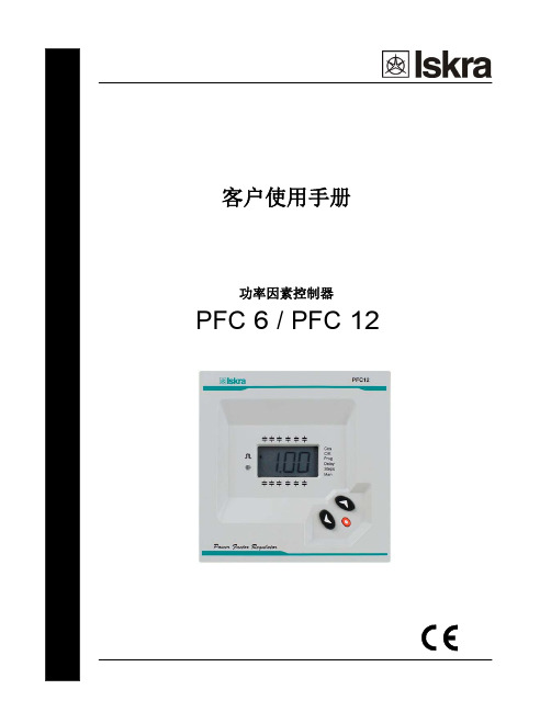
PFC-6控制器使用说明书
-轻松安装,无须其他工具
-前面板编程:(3 个功能键)。
-尺寸符合 DIN43 700 of 144 x 144 mm
-测量和电源同一输入。
1.1 控制器记录检查 控制器记录检查如下: 该设备在运输过程中无破损 所提供型号和预定的相一致
检查控制器背面的标签
根据型号 显示输出继电器数 PFC6 6 路 PPFFCC162:162 路路
电流互感器连接错误 (S1-S2倒相或者连接错误). 补偿过量. 要求断开继电器 补偿不足 连接所有继电器
3.1. 浏览功能键
根据控制器使用的不同操作模式,浏览功能键体现不同的功能。操 作模式如下:
普通模式 控制器通过此模式来测试cos φ和调节电容器投切。
设置模式
模式下允许设定控制器参数。 不同模式下按键的功能如下: 普通模式
6段 12 段
数。
-根据类型 6 路及 12 路控制器。
-投入段数显示,电子显示 cos φ 值与无功功率 L(电感性)和 C(电容性)的区别符号。
-3 位 7 段的数字液晶显示器。
-设置参数且无需断开调节器的电源。
-可设定调节器,即使在调节电容器的过程中
-可选择使用 50 或 60 赫兹的频率。
-所有的测量都显示在同一的显示器上
4. 安装和设置 本手册包含的信息和警告,用户必须遵循并保持设备在一个适当安全的工作秩序下使用。
如果该设备没有在制造商制定方式下被使用,设备保护可能受到损害。
如果发现设备有磨损的迹象或不正常运行,必须切断该设备的电源。在这种情况下,请联 系合格的服务代表。 为了安全使用PFC 6 或者 PFC 12 控制器,至关重要的是,安装或操作的技术人员是按照 正常安全程序,以及在本指导手册中的具体警告事项来操作。
RVT-6功率因数控制器使用说明书

7
3. 簡易啟動
3.1. 導讀操作功能
1 2 3 4 5 6 7 8 9 10 11 12 13 14 15 16
Welcome Measurements Settings Bank monitoring About RVT
set使用按rvt安裝與使用手冊11settings關于rvtaboutrvt列印設定值printsettings改變模式changemode測試功能testfunctionmanualsettingscommissioning電容器組監測bankmonitoringtestfantestalarm列印print事件記錄eventloggingsystemvaluesmanual通信串communication明暗tempunitsetlanguagetestoutputs電容器組banksettingsinstallationsettingsusersettings值重置restoredefaultsettingsalarmloggingdiagnosisrvt安裝與使用手冊12顯示最大值vrms電壓有效值rms可達690vac1100kvv1基本頻率的有效值rms可達690vac1100kvfrequenБайду номын сангаасyhz基本電壓頻率45hz65hz0540hz70hzthdv03001300harmtableharmchart電流有效值rms05a1100kai1基本頻率的有效值rms05a1100kathdi03001300harmtableharmchart功率功率功率功率cos?2基本波功率因數21100211pf3功率因數3110021有效功率010kw20100mwvar無效功率010kvar20100mvarva視在功率010kva20100mva尚需補足之功率010kvar20100mvar40c105ct21範圍值必須乘以ct比值irmsi1pqsq和pt比值vrms注釋說明
nokia NC-12 功率因数调整器
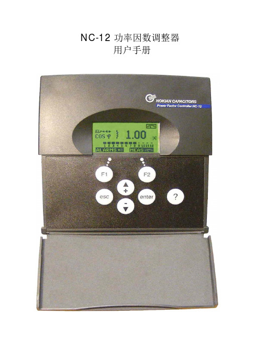
3(51)
NC-12 功率因数控制器
1.3 描述
前视图:
用户手册
A E
图例
A
显示屏
B
按键
C
开盖口
D
盖板
E
盘面安装的安装支架
B
D C
4(51)
NC-12 功率因数控制器
用户手册
后视图:
H M
L
F
G
K
J
I
图例
F G H I J K L
M
调整器输出继电器的接线端子 铭牌 盘面安装用安装支架 DIN 轨道安装的固定弹簧 调整器的电流,电压,温度传感器,目标功率因数的输入接线端子 风扇及报警输出 DIN 轨道安装的安装区
5.1 概述 ...................................................................................................................................... 12 5.2 主菜单................................................................................................................................... 14 5.3 电容器组的预先配置 ............................................................................................................. 16 5.4 调试 ...................................................................................................................................... 19
REGO应用手册
自动功率因数控制器
应用手册
修订本0-硬件4.01:2009.9
目录
1) 控制器注意事项 ........................................................................................... 1 2) 第一次启动步骤 ............................................................................................. 1 3) 安全 ............................................................................................................... 2 4) 综合说明 ........................................................................................................ 3 5) 控制器如何工作 ............................................................................................. 4 6) 主接线 ............................................................................................................. 4 7) C.T.安装说明 ............................................................................................... 4 8) 第一次启动 ..................................................................................................... 6 9) 后续启动 ......................................................................................................... 7 10) 控制性能测试 ................................................................................................ 8 11) 参数设置 ......................................................................................................... 8 12) 测量显示 ........................................................................................................ 16 13) 附加功能 ........................................................................................................ 16
YAMAHA GF24 12 GF16 12 GF12 12功率放大器 说明书
的电源线有引起火灾或电击的危险。 ● 切勿拆卸本机的罩盖。若不遵守、则会引起电击。若
您认为需要进行内部检查、维修或修理、请与经销 商联系。
● 切勿改造本机、这样做会引起火灾或电击的危险。 ● 若已经发生雷电、请尽快关断电源开关、并且从电
源插座拔出电源线。 ● 若可能发生雷电、在接线的状态下切勿触摸电源线。
请远离本机使用电话。
前言
非常感谢您购买 Yamaha 的 GF24/12,GF16/12 或者 GF12/12 型混频控制台。 这些型号的混频控制台各提供有充足的 12 种输出接口,并适应从音乐会声音的增强到安 装系统的应用范围的丰富变化。为了充分发挥混频控制台的功能以及保证无故障地长期使 用,请认真阅读本手册。
功率放大器
用户手册
妥善保存手册以备以后参考。
C
注意事项
— 为安全操作 —
警告
安装 ● 仅可将本机的电源线与本用户手册中述及、以及在
本机上标出型号的AC电源插座连接。若不遵守、则 会引起火灾或电击的危险。 ● 切勿使水侵入本机或使本机受潮。若不遵守、则会 引起火灾或电击。 ● 切勿将装有液体的容器或小型金属物品放置在本机 的顶部。若液体或金属物品 侵入本机, 则会引起火 灾或电击的危险。 ● 切勿将重物(包括本机)放置在电源线上。损坏的电 线有引起火灾或电击的危险。尤其应注意、切勿将 包裹地毯的重物放置在电源线上。
20
10
20
10
20
10
20
10
20
10
20
10
20
10
30
PRE 10
30
PRE 10
30
N-6&12操作实务

进入下一项
电流过低
MEASURE(测量选单)
MEASURE
按 ESC
Hale Waihona Puke 系统电压按 ENTER COS∮
U.LL THD.U I P Q S T
进入下一项
MEASURE(测量选单)
MEASURE
谐波电压畸变率
按 ENTER COS∮
U.LL THD.U I P Q S
T
进入下一项
MEASURE(测量选单)
按 ESC
根据实际接线来设定且 必须和电流设定相匹配
按 ENTER CT
VOLTAGE PROGRAM STEP.SEQ N.STEPS VERIFY STEP.TST LANGUAG
L1-N L2-N L3-N L1-L2 L2-L3 L3-L1
WIRING COS PHI
MANUAL
AUTO
DELAY
ENTER
进入/确定
进入下一项
PARAMET(参数选单)
PARAMET
按 ESC
设定重新投入延时
按 ENTER CT
VOLTAGE WIRING COS PHI PROGRAM STEP.SEQ N.STEPS VERIFY STEP.TST LANGUAG
MANUAL
AUTO
DELAY
ENTER
PARAMET(参数选单)
PARAMET
按 ESC
设定配线
按 ENTER CT
VOLTAGE WIRING COS PHI PROGRAM STEP.SEQ N.STEPS VERIFY STEP.TST LANGUAG
MANUAL
AUTO
DELAY
