Agilent 8169A偏振控制器
Agilent8164可调激光 器使用介绍

Agilent 8164A系统配置菜单
• 按下Config硬键访问系统主机的配置参数
设置GPIB地址
按下Help硬键 Index软键,可获取帮助索引
解锁激光源
按下Config键 选择Unlock
Agilent 8164A帮助
• 按下Help硬键 Index软键,可获取帮助索引
访问应用程序
• 按下Appl硬键,可访问Agilent 8164A光波测量系统的应用程序
PACT应用程序
• 执行IL测量
1、在设置屏幕下,按下[Menu],移至<Setup>,并按下Enter键。
2、将待测器件连入光路,按下[Measure],出现PACT测量屏幕,如下图所示。
• 3、PACT测量结果
动态范围低
动态范围高
谢 谢 大 家!
Agilent 8164A用户界面的说明
Agilent 8164A屏幕概观
该屏幕在启动时立刻显示,显示所有已安装模块的重要参数
可调激光器通道的细节
选择波长通道,按下[details]软键,可访问未显示在概观屏幕上的模块参数
功率传感器通道的Agilent 8164A菜单
按下[Menu]软键显示功率传感器通道的菜单
必须在Agilent8164A光波测量系统中安装可调谐激光模块和功率计。 根据使用的系统配置,可以测量波长中的插入损耗(单通道功率测量)
设置PACT:
1、按下Appl键。应用程序菜单出现,如下图所示。
PACT应用程序
2、移至<PACT>并按下Enter键。 PACT设置屏幕出现,如下图所示。
3、移至模块选择对话框。默认情况下,选定具有最低槽号的 可调谐激光模块。移至[laser selection],按下[Edit].
Agilent-眼图、抖动、相噪
Agilent——眼图、抖动、相噪随着数据速率超过Gb/s水平,工程师必须能够识别和解决抖动问题。
抖动是在高速数据传输线中导致误码的定时噪声。
如果系统的数据速率提高,在几秒内测得的抖动幅度会大体不变,但在位周期的几分之一时间内测量时,它会随着数据速率成比例提高,进而导致误码。
新兴技术要求误码率(BER),亦即误码数量与传输的总码数之比,低于一万亿分之一(10-12)。
随着数据通信、总线和底板的数据速率提高,市场上已经出现许多不同的抖动检定技术,这些技术采用各种不同的实验室设备,包括实时数字示波器、取样时间间隔分析仪(TIA)、等时取样示波器、模拟相位检波器和误码率测试仪(BERT)。
为解决高数据速率上难以解决的抖动问题,工程师必需理解同步和异步网络中使用的各种抖动分析技术本文重点介绍3 Gb/s以上新兴技术的数据速率。
低于3 Gb/s的实时示波器可以捕获连续的数据流,可以同时在时域和频域中分析数据流;在更高的数据速率上,抖动分析要更具挑战性。
本文将从数字工程师的角度,介绍应对SONET/SDH挑战的各种经验。
抖动分析基本上包括比较抖动时钟信号和参考时钟信号。
参考时钟是一种单独的黄金标准时钟,或从数据中重建的时钟。
在高数据速率时,分析每个时钟的唯一技术是位检测和误码率测试;其它技术则采用某种取样技术。
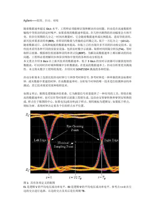
如图1所示,眼图是逻辑脉冲的重叠。
它为测量信号质量提供了一种有用的工具,即使在极高的数据速率时,也可以在等时取样示波器上简便生成。
边沿由‘1’到‘0’转换和‘0’到‘1’转换组成,样点位于眼图的中心。
如果电压(或功率)高于样点,则码被标为逻辑‘1’;如果低于样点,则标为‘0’。
系统时钟决定着各个位的样点水平位置。
图1: 具有各项定义的眼图E1是逻辑‘1’的平均电压或功率电平,E0是逻辑‘0’的平均电压或功率电平。
参考点t = 0在左边的交点进行选择,右边的交点及其后是位周期TB。
Eye Crossing Point: 眼图交点Left Edge: 左沿Right Edge: 右沿Nominal Sampling Point: 标称样点幅度噪声可能会导致逻辑‘1’的电压或功率电平垂直波动,低于样点,导致逻辑‘1’码错误地标为逻辑‘0’码,即误码。
Agilent-GCMS培训(完整版330页)
进样口和检测器出口
气路连接口
电缆连接口
电源连接口
炉箱冷却风进口
Agilent 7890A 键盘介绍
*
运行按键
气相部件按键
数字按键
信息按键
方法存储和自动运行按键
维护按键
*
Agilent GC6890前视图
*
Agilent GC6890侧后视图
*
即时功能键 功能键 快捷键 信息键 数字键 多功能键 方法存贮与自动 运行
MSD
10-5 Torr
<2 mL/min
760 Torr
0.5 - 15 mL/min
传输线
*
气相色谱和质谱的联用技术——传输线
传输线
涡轮泵
自动进样器
离子源
炉箱
*
色谱柱
流量 控制器
稳压器
空气
氢气
载气
分子筛
脱水管
固定
进样口
检测器
电子部件
PC
限流器
典型的气相色谱
*
分子筛 P/N 5060-9084
(0 to 218 V)
Signal Out
EM Voltage
电子倍增器
电压有使用上限(3000伏) 电压的提高,可以提高检测器的信号
*
电子倍增器的寿命曲线
*
提供足够的平均自由程 提供无碰撞的离子轨道 减少离子-分子反应 减少背景干扰 延长灯丝寿命 消除放电 增加灵敏度
为什么MS需要真空
空气压力应为 80 psi。
推荐管线压力
氢气压力应为 60 psi。
载气必须通过控制形成恒定的压力和恒定的流量。上下游控制器压差保持1公斤以上。
ARTISAN技术组-设备说明书

ErrataTitle & Document Type:Manual Part Number:Revision Date:HP References in this ManualThis manual may contain references to HP or Hewlett-Packard. Please note that Hewlett-Packard's former test and measurement, semiconductor products an d chemical analysis businesses are now part of Agilent Technologies. We have made no changes to this manual copy. The HP XXXX referred to in this document is now the Agilent XXXX. For example, model number HP8648A is now model number Agilent 8648A.About this ManualWe’ve added this manual to the Agilent website in an effort to help you support your product. This manual provides the best information we could find. It may be incomplete or contain dated information, and the scan quality may not be ideal. If we find a better copy in the future, we will add it to the Agilent website.Support for Your ProductAgilent no longer sells or supports this product. You will find any other available product information on the Agilent Test & Measurement website:Search for the model number of this product, and the resulting product page will guide you to any available information. Our service centers may be able to perform calibration if no repair parts are needed, but no other support from Agilent is available.16500B/16501A Logic Analysis System User's Reference 16500-97010April 1994U s er’s Ref er encePubl i c a t i on num be r16500-97010Fi r s t edi t i on,Apr i l1994For Sa f e t y i nf or m a t i on,W a r r a nt i es,a nd Reg ul a t or yi nf or m a t i on,s ee t he pa ges be hi nd t he i nde x©Copyr i g ht Hewl et t-Pac ka r d Com pa ny1987,1990,1993,1994 Al l Ri ght s Re s er v edHP 16500B/16501ALogi c Anal ys i s Sys t emI n Thi s BookW el c om e t o t he He wl et t-Pac ka r d Logi c Ana l y s i s Sys t em!The HP 16500B Logi c Ana l y s i s Sys t em i s des i gned t o be t heea s i es t s ys t em t o us e,ev e r.I t s m odul a r des i gn a l l ows you t o c onf i gur e i t wi t h j us t t he m ea s ur em ent m odul es you need now, yet a dd ot he r m odul es l a t e r.Thi s r e f er enc e expl a i ns t he oper a t i on of t he s ys t em m a i nf r a m e a nd I nt er m odul em enus.Al s o i nc l ude d i s i nf or m a t i on ont he m os t c om m on s ys t em opt i ons.O r gani zat i onW hen you or der t he HP 16500B,you get t wo bi nder s(one i s ext r a f or l a t e r us e). The m a i nf r a m e r e f er enc e i nf or m a t i on i s f ound be hi nd t he f i r s t t a b "HP 16500BM a i nf r a m e."I nf or m a t i on on t he opt i ona l keyboa r d,m ous e,a nd t he HP 16501A Expa ns i onFr a m e i s f ound behi nd t he s ec ond t a b, "Sys t em Opt i ons."As you a c c um ul a t eot her s ys t em opt i ons,pl a c e t hes er ef er e nc es behi nd t hi s t a b.Behi nd t he t hi r d t a b "Com m on M odul e Oper a t i ons"i s i nf or m a t i on c om m on t om os t m odul es,l i ke i ns t a l l i ng m odul e s,us i ng s ym bol s,a nd a s s i gni ng l a bel s.As you pur c ha s e a ddi t i ona l m ea s ur em ent m odul es,pl a c e t hei r r ef er e nc es a t t heba c k of t hi s bi nde r or i n t he s e c ondbi nder.W hat i s i n t he H P 16500B Us er’s Ref er ence?•Cha pt e r1 i nt r oduc es t he HP 16500B by s um m a r i z i ng i t s f ea t ur es.•Cha pt e r2 di s c r i bes t he m a i nf r a m e’s Sys t em Conf i g ur a t i on m e nu.•Cha pt e r3 di s c r i bes t he HP-I B a nd RS-232C i nt er f a c es.They a r e us ed f or pr i nt i ng s c r eens a nd c om put e r c ont r ol l ed m ea s ur em ent s.•Cha pt e r4 expl a i ns how t o pr i nt s c r eens t o v a r i ous g r a phi c s pr i nt er s.•Cha pt e r5 di s c r i bes t he f l exi bl e di s k a nd ha r d di s k ope r a t i ons.•Cha pt e r6 des c r i bes t he Sys t em Ut i l i t i es m enu.Adj us t m ent s t o t he r ea l-t i m e c l oc k,t ouc h c a l i br a t i on,a nd s c r een c ol or s a r e m a de her e.•Cha pt e r7 expl a i ns how t o m a ke i nt er m odul e m ea s ur em ent s.•Cha pt e r8 l i s t s t he i ns t r um ent s pec i f i c a t i ons a nd c ha r a c t er i s t i c s.•Cha pt e r9 expl a i ns t he gener a l i ns t r um ent m a i nt ena nc e a nd r epa c ki ngi nf or m a t i on.Al s o i nc l uded i s a des c r i pt i on of t he s el f-t es t t ha t i sper f or m ed when t he i ns t r um e nt i s t ur ned on.•Cha pt e r10 des c r i bes a l l s y s t e m a nd di s k er r or m es s a ges.W hat i s i n t he Sys t em O pt i ons?•Cha pt e r1 expl a i ns t he key boa r d a nd m ous e opt i ons.•Cha pt e r2 des c r i bes t he HP 16501A Expa ns i on Fr a m e opt i on.Ev en t hough you m a y not ha v e pur c ha s e d t he s e opt i ons yet,keep t hi si nf or m a t i on f or pos s i bl e f ut ur e us e.W hat i s i n t he C om m on M odul e O per at i ons?•Cha pt e r1 des c r i bes a s s i gni ng l a bel s.•Cha pt e r2 des c r i bes us i ng s ym bol s.•Cha pt e r3 expl a i ns t he gener a l i ns t a l l a t i on f or i ndi v i dua l m odul es.W her e t o go nextI f you ha v en’t a l r ea dy r ea d Se t t i ng Up The HP 16500 Logi c Anal ys i sSys t e m,pl ea s e r ea d i t be f or e c ont i nui ng.M S-DOS®i s a US r egi s t er e d t r a de m a r k of M i c r os of t Cor por a t i on.Cont ent sH P 16500BM ai nf r am e1W hat I s t he H P 16500B Logi c A nal ys i s Sys t em?Ke y Fea t ur es 1–3Opt i ona l Fea t ur es 1–3Us er I nt er f a c es1–4Def a ul t Conf i gur a t i ons 1–4Ac c es s or i es Suppl i ed 1–5Ac c es s or i es Av a i l a bl e 1–52The Sys t em Conf i gur at i on M enuGe t t i ng i nt o t he Sys t em Conf i g ur a t i on M enus 2–4La yout of t he Sy s t e m Conf i gur a t i on M enus 2–5Sl ot Des i gna t or s 2–63C onf i gur i ng t he H P-I B and RS-232CConf i gur i ng t he HP-I B I nt er f a c e3–4Conf i gur i ng t he RS-232C I nt er f a c e3–5Conf i gur i ng t he I nt er f a c e f or a Cont r ol l er or Pr i nt er 3–84C onnect i ng a Pr i nt erConne c t i ng HP-I B Pr i nt e r s 4–3Conne c t i ng RS-232C Pr i nt e r s 4–6Conne c t i ng t o Ot he r Hewl et t-Pa c ka r d Pr i nt er s 4–9Pr i nt i ng t he Di s pl a y 4–11Cont ent s–1Contents5The D i s k D r i ve M enusAc c es s i ng t he Di s k M enus 5–5I ns t a l l i ng a Fl exi bl e Di s k 5–6Sel e c t i ng a Di s k Oper a t i on 5–7Loa di ng a Fi l e 5–8For m a t t i ng a Di s k 5–10St or i ng Fi l es on a Di s k 5–12Rena m i ng a Fi l e 5–15Aut ol oa di ng a Fi l e 5–17Pur gi ng a Fi l e 5–19Copy i ng a Fi l e 5–20Pac ki ng a Di s k 5–22Dupl i c a t i ng a Di s k 5–23M a ki ng a Di r e c t or y 5–24Cha ngi ng t he Di r ec t or y 5–25Cr ea t i ng a Sys t em Fl e xi bl e Di s k 5–266The Sys t em Ut i l i t i es M enuThe Touc h a nd Sound Fi el ds 6–4Touc h Ca l i br a t i on 6–4Set t i ng t he Rea l-t i m e Cl oc k 6–6Tur ni ng t he Sound On/Of f 6–7Di s pl a y Col or Se l ec t i on 6–8Sel e c t i ng t he Col or,Hue,Sa t ur a t i on,a nd Lum i nos i t y Fi e l ds 6–10 Sel e c t i ng Col or s 6–12Ret ur ni ng t o t he De f a ul t Col or s 6–14Cont ent s–2Contents7I nt er m odul e M eas ur em ent sAc c es s i ng t he I nt er m odul e M enu 7–5Conf i gur i ng a Gr oup Run 7–6Conf i gur i ng Por t I n/Out 7–8The Gr oup Run/St op Fi el d 7–10The M odul es Li s t 7–11St a t us I ndi c a t or s a nd Ti m e Cor r el a t i on Ba r s 7–12Adj us t i ng Ske w 7–13W ha t Ar e Som e Typi c a l I nt er m odul e M e a s ur em e nt s?7–14Di s pl a y i ng M ul t i pl e M odul e Da t a on One Sc r een 7–18Hel pf ul Hi nt s 7–218G ener al Char act er i s t i csCha r a c t e r i s t i c s8–29M ai nt ai ni ng t he H P 16500BCl ea ni ng Requi r e m ent s9–2Dega us s i ng 9–3Ser v i c e a nd Ca l i br a t i on 9–3The Sys t em Tes t M enu 9–4Repa c ka gi ng f or St or a g e or Shi pm e nt 9–510Er r or M es s agesDi s k Er r or M es s a ges 10–3Di s k W a r ni ng M e s s a ge s10–5Power up Sel f-Tes t Doc um ent a t i on 10–6Fai l Codes 10–7Cr i t i c a l Er r or s10–8Non-Cr i t i c a l Er r or s10–8Cont ent s–3ContentsSys t em O pt i ons1Us i ng t he O pt i onal K eyboar d and M ous eM ov i ng t he Cur s or1-3Ent er i ng Da t a i nt o a M enu 1-5Us i ng t he Keyboa r d Ov er l a ys1-7Def i ni ng Ti m e Uni t s1-9Def i ni ng Vol t a ge Uni t s1-9As s i gni ng Edge Tr i gge r s1-10Cl os i ng a M enu 1-10Conne c t i ng t he Ke yboa r d a nd M ous e1-112The O pt i on H P 16501A Expans i on Fr am eCom ponent Det a i l s2-3Sys t em Conf i g ur a t i on 2-4Sys t em Ar m i ng a nd Tr i gg er i ng 2-4Conne c t i ng t he HP 16501A Expa ns i on Fr a m e 2-7 Com m on M odul eO per at i ons1Label s As s i gnm entLa bel As s i gnm ent Fi el ds1-3Rol l i ng La bel s a nd Pods1-52Sym bol s As s i gnm entSym bol s Fi e l d 2-33I ns t al l i ng and Rem ovi ng Car dsGe ner a l I ns t a l l a t i on Pr oc e dur e 3-3HP 16532A I ns t a l l a t i on Cons i de r a t i ons3-7HP 16517A/18A I ns t a l l a t i on Cons i der a t i ons3-11Cont ent s–41W hat I s t heH P 16500B Logi c Anal ys i s Sys t em?The H P 16500BThe HP 16500B i s t he m a i nf r a m e of t he Hewl e t t-Pa c ka r d Logi cAna l y s i s Sys t em.I t of f er s a m odul a r s t r uc t ur e f or pl ug-i n c a r ds wi t h a wi de r a ng e of s t a t e,t i m i ng,os c i l l os c ope,a nd pa t t er n g ener a t orc a pa bi l i t i es.Thi s a l l ows you t o c onf i gur e t he HP 16500B us i ng onl yt he m odul es you nee d i n or der t o per f or m a des i r ed m ea s ur em ent or s e t of m ea s ur em ent s,whi l e g i v i ng y ou t he f l exi bi l i t y t o c ha nge or upda t e t he m l a t er.The Log i c Ana l ys i s Sys t em pr ov i de s bot h exper i e nc e d a nd f i r s t-t i m e us er s wi t h power f ul m ea s ur em ent c a pa bi l i t i es.The pop-up m enusa nd c ol or gr a phi c s l ea d y ou t hr ough s et ups a nd m ea s ur e m e nt s qui c kl y a nd ea s i l y,wi t hout t he need t o m em or i z e a l ot of s t e ps.By t ouc hi ngt he a ppr opr i a t e f i el ds or us i ng t he c ur s or of ei t he r t he opt i ona l m ous e or keyboa r d,you c a n per f or m f unc t i ons,c onf i gur e m enus,a nd m ov ef r om one m e nu t o a not her.W i t h t he i nt er m odul e c a pa bi l i t i es of t he Logi c Ana l y s i s Sys t em,youc a n m a ke i nt e r a c t i v e m e a s ur em ent s be t ween m odul es.Thi s a l l ows you t o c onf i gur e m odul e s t o i nt er a c t wi t h ea c h ot her,us i ng t het r i g ger i ng c a pa bi l i t i es of one m odul e a nd t he a c qui s i t i on c a pa bi l i t i es of a not her.Syst em O pt i onsThe HP 16501A i s t he a dd-on m a i nf r a m e f or expa ndi ng t he m odul ec a pa c i t y of t he HP 16500B.W he n t he HP 16501A i s c onnec t ed t o t he HP 16500B,t heyf unc t i on a s a s i ngl e t en-c a r d s y s t em whi c h i s t ur ned on a nd c ont r ol l ed by t he HP 16500B.The HP 16501A f or m s a t i ght l y c oupl ed s ys t e m wi t h t he HP 16500B,per m i t t i ng ea ch of t he t wom a i nf r a m e s t o a r m or t r i g ger a ny m odul e f r om a ny ot her m odul e.An opt i ona l LAN i nt e r f a c e i s a v a i l a bl e f or di r ec t c onnec t i on t oc om put e r s l oc a t ed on a n Et her net l oc a l a r ea net wor k (LAN).The LAN i nt erf a c e ena bl es you t o upl oa d m e a s ur em ent da t a f or t he m os t c om pr ehens i v e pos t-pr oc es s i ng nee ds a nd ea s y a c c es s t o da t a f i l e s.1–2Key Feat ur esThe key f e a t ur es of t he HP 16500B a r e:•M odul a r m a i nf r a m e wi t h f i v e c a r d s l ot s .•9-i nc h c ol or m oni t or .•Touc hs c r e en wi t h on/of f c ont r ol .•Ba t t er y ba c ked Re a l -t i m e c l oc k.•Pr ogr a m m a bl e PORT I N v ol t a ge l ev e l a nd e dge s el ec t i on.•3.5-i nc h f l exi bl e di s k dr i v e wi t h DOS a nd LI F f or m a t s uppor t .•170 M by t e ha r d di s k dr i v e wi t h DOS f or m a t s uppor t .•I nt e r m odul e t r i gge r i ng a nd 2 ns t i m e c or r el a t i on of a c qui r ed da t a .•HP-I B a nd RS-232C i nt er f a c es f or :— Ha r dc opy out put t o a pr i nt er— Cont r ol l er i nt er f a c e .O pt i onal Feat ur esThe opt i ona l f e a t ur es of t he HP 16500B:•HP16501A Expa ns i on Fr a m e. I nc r ea s e a v a i l a bl e c a r d s l ot s t o t en whe n you c onnec t t he expa ns i on f r a m e t o a n HP 16500B.•M ous e.•Ke yboa r d.•Et her net LAN i nt er f a c e .•Expa nda bl e s ys t em m em or y up t o 64 M byt e s .See Also "Sys t em Opt i ons " f or m or e i nf or m a t i on on a v a i l a bl e s ys t em s of t wa r e a ndha r dwa r e opt i ons .What is the HP 16500B Logic Analysis System Key Features1–3What is the HP 16500B Logic Analysis SystemUser InterfacesU s er I nt er f acesThe HP 16500B ha s f our us er i nt e r f a c e dev i c es:t he knob on t he f r ont pa nel,t he t ouc hs c r ee n,t he opt i ona l m ous e,a nd t he opt i ona l key boa r d.The knob on t he f r ont pa nel i s us ed t o m ov e t he c ur s or on c er t a i n m enus,i nc r em ent or de c r em ent num e r i c f i e l ds,a nd t o r ol l t he di s pl a y.The t ouc hs c r e en f i e l ds c a n be s el ec t e d by t ouc h or wi t h t he opt i ona l m ous eor key boa r d.To a c t i v a t e a f i e l d by t ouc h,pr es s t he da r k bl ue f i e l d on t hedi s pl a y wi t h your f i ng er unt i l t he f i el d c ha ng es c ol or.Then m ov e your f i nge ra wa y f r om t he s c r een t o a c t i v a t e y our s el ec t i on.You ha v e t he opt i on ofdi s a bl i ng t he t ouc hs c r e en wi t h t he f r ont-pa ne l Touc h On/Of f but t on.See Also The "Sy s t e m Opt i ons"pa r t f or m or e i nf or m a t i on on us i ng t he opt i ona lke yboa r d a nd m ous e.Scr een C ont r as t and Br i ght nes sSc r een c ont r a s t a nd br i ght nes s a r e a dj us t ed by t ur ni ng t he t wo s m a l l knobsl oc a t ed be nea t h t he Touc h Sc r ee n but t on.The l e f t knob i s f or br i ght nes s a ndt he r i ght knob i s f or c ont r a s t.D ef aul t Conf i gur at i onsW hen t he i ns t r um e nt i s power ed up,pr edet er m i ned v a l ue s a r e a ut om a t i c a l l ya s s i gned t o t he di f f er ent f i e l ds of t he m e nus t o c onf i gur e t he i ns t r um ent f orba s i c m ea s ur em ent s.Thi s a l l ows y ou t o m a ke a ba s i c m ea s ur e m ent byt ur ni ng on t he i ns t r um ent,c onnec t i ng t he pr obes,a nd t ouc hi ng t he Runf i el d.Of t en,onl y m i nor c ha nges a r e ne eded f or m or e c om pl e x m ea s ur e m ent s.St or i ng D ef aul t C onf i gur at i onsThe def a ul t c onf i gur a t i ons m a y be s t or e d on a di s k f or l a t er us e or r es et byc yc l i ng t he power.St or i ng de f a ul t c onf i g ur a t i ons on a di s k i s a c onv eni entwa y t o r et ur n t o t he def a ul t v a l ue s wi t hout c yc l i ng t he power.Def a ul t v a l uesf or ea c h m odul e c a n be s t or e d s epa r a t el y or t oget her i n one f i l e.See Also The "Us i ng t he Di s k Dr i v e M e nus"c ha pt er f or m or e i nf or m a t i on on t he St or e ope r a t i on.1–4What is the HP 16500B Logic Analysis SystemAccessories SuppliedAcces s or i es Suppl i edThe f ol l owi ng l i s t of a c c es s or i es i s s uppl i e d wi t h t he HP 16500B Logi cAna l y s i s Sys t em.I f a ny a c c es s or y i s m i s s i ng,c ont a c t your l oc a l s a l es of f i c e. Accessories Supplied QtyTraining Kit1User’s Reference Guide1Programming Reference Guide1Service Guide1Setting Up the System Guide1RS-232C Loopback Connector1Power Cord1Disk pouch containing composite software1Feeling Comfortable With Logic Analyzers guide1Feeling Comfortable with Digitizing Oscilloscopes guide1Filler Panels**Quant i t y depends on how m any m odul es ar e or der ed w i t h t he HP 16500B/16501AAcces s or i es Avai l abl eOt her a c c es s or i es a v a i l a bl e f or t he HP 16500B/16501A Logi c Ana l y s i s Sys t em a r e l i s t ed i n t he Ac c e s s or i e s f or HP Logi c Anal yze r s br oc hur e.1–51–62The Sys t em Conf i gur at i on M enuThe Sys t em Conf i gur at i on M enuThe Sys t em Conf i gur a t i on m enu i s t he f i r s t m enu you s ee a f t er t hei ni t i a l power-up of t he i ns t r um ent.Thi s m enu l i s t s t he m odul es a nds of t wa r e opt i ons t ha t your s y s t em i s c onf i g ur ed wi t h a nd s howswhet her t her e a r e f i v e c a r d s l ot s(t he HP 16500B a l one)or t en c a r ds l ot s(t he HP 16500B wi t h t he opt i ona l HP 16501A a t t a c hed)a v a i l a bl e.I t a l s o s hows i f ei t her t he opt i ona l m ous e or keyboa r d i sc onnec t ed.I f a m ous e i s c onnec t e d,t he s ys t e m c onf i gur a t i on m enui ndi c a t es whet her t he m ous e i s c onnec t e d di r ec t l y t o t he HP 16500Bor t o a keyboa r d c onnec t ed t o t he m a i nf r a m e.Fi na l l y,t he s ys t e mc onf i gur a t i on m e nu g i v es you a c c e s s t o t he c onf i gur a t i on of t he HP-I B, RS-232C,a nd opt i ona l LAN i nte rf a c es.2–2The System Configuration Menu M enu M apThe f ol l owi ng m e nu m a p i l l us t r a t e s a l l f i el ds a nd a v a i l a bl e opt i ons i nt he Sys t em Conf i g ur a t i on m enu.The m enu m a p wi l l hel p you ge t a nov er v i ew a s wel l a s pr ov i de you wi t h a qui c k r ef er e nc e of wha t t heSys t e m Conf i gur a t i on m enu c ont a i ns.System Configuration Menu Map2–3G et t i ng i nt o t he Sys t em Conf i gur at i on M enusI n t he upper -l ef t c or ne r of t he m enu a r e t wo f i e l ds t ha t i ndi c a t e t he c ur r ent m enu a nd m odul e. The f i e l d t o t he e xt r em e l ef t (Sys t em ) s hows you whi c h m odul e y ou’r e i n a nd t he one t o t he r i g ht of t he m odul e f i el d (Conf i gur a t i on)s hows you wha t m enu wi t hi n t he m odul e y ou’v e a c c es s ed.To a c c e s s t he Sy s t e m Conf i gur a t i on m enu, f ol l ow t hes e s t eps :1I f t he m odul e f i el d i n t he upper -l ef t cor ner of t he s c r een doe s notdi s pl ay "Sys t em ," s el ect t hi s f i e l d and w he n t he pop-up appe ar s , s el ect System. Thi s w i l l g et y ou i nt o one of t he Sy s t em m enus .2I f t he m odul e f i el d i n t he upper -l ef t cor ner of t he s c r een di s pl ay s "Sy s t em ," but t he m enu f i el d t o t he r i ght of Sys t em doe s n’t di s pl ay "Conf i gur at i on," s el ect t hi s f i el d. W hen t he pop-up appear s , s e l ec t Configuration t o di s pl ay t he Sys t e m Conf i gur at i on m enu.Module and Menu FieldsThe System Configuration Menu Getting into the System Configuration Menus2–4The System Configuration MenuLayout of the System Configuration MenusLayout of t he Sys t em Conf i gur at i on M enusThe f i g ur e bel ow s hows t he l a yout of t he Sys t em Conf i g ur a t i on m e nu f or t he HP 16500B.The f i g ur e i s l a bel l ed wi t h t he m a j or f e a t ur es a nd f unc t i ons oft he m enu.ModuleModuleModuleModuleModuleSystem Configuration Menu2–5The System Configuration MenuSlot DesignatorsSl ot D es i gnat or sThe s l ot des i gna t or s a r e l i s t ed a s A t hr ough E f or t he HP 16500B a l one,or A t hr ough J f or t he HP 16500B wi t h t he HP 16501A a t t a c hed.The s l otdes i gna t or s a r e di s pl a yed t o t he l ef t of t he l i s t of c a r ds f or t he s y s t e m a nd i ndi c a t e t he l oc a t i ons or s l ot s f or e a c h c a r d.W he n you s el ec t t he M odul ef i el d,a pop-up a ppe a r s.The l et t e r s a f t er t he na m e of ea c h m odul e i ndi c a t e t he l oc a t i on of ea c h “m a s t e r”c a r d f or t ha t m odul e.Slot Designators in Master Frame2–63Conf i gur i ng t heH P-I B and RS-232CThe H P-I B and RS-232C I nt er f acesThi s c ha pt e r des c r i bes t he c ont r ol l er a nd pr i nt e r i nt er f a c e s a nd t hei r c onf i gur a t i ons.I t de f i ne s t he HP-I B i nt er f a c e a nd des c r i bes how t os e l ec t a ny one of t he 31 di f f er e nt HP-I B a ddr e s s es a v a i l a bl e.I t a l s o def i nes t he RS-232C i nt e r f a c e a nd t el l s y ou how t o s el ec t a ba ud r a t e, how t o c ha nge t he s t op bi t s,how t o s et t he pa r i t y a nd da t a bi t s,a nd how t o c ha nge t he pr ot oc ol.Controller and Printer Configuration3–2Configuring the HP-IB and RS-232C The C ont r ol l er I nt er f aceThe HP 16500B i s e qui pped wi t h a s t a nda r d RS-232C i nt er f a c e a nd a n HP-I B i nt er f a c e t ha t a l l ow you t o c onne c t t o a c ont r ol l er.Thi s gi v e s you r em ot e a c c e s s f or r unni ng m ea s ur em ent s,f or upl oa di ng a nd downl oa di ng c onf i g ur a t i ons a nd da t a,f or pr i nt i ng,a nd m or e.Thec ont r ol l er i nt er f a c e i s e xpl a i ned i n m ore det a i l i n t heHP 16500B/16501A Pr ogr am m er’s Gui de.The Pr i nt er I nt er f aceThe HP 16500B c a n out put i t s s c r een di s pl a y t o v a r i ous HP-I B a ndRS-232C g r a phi c s pr i nt e r s.Conf i gur ed m enus,wa v ef or m s,a nd ot her da t a c a n be pr i nt ed f or c om pl et e m ea s ur em ent doc um ent a t i on.Thepr i nt er i nt er f a c e i s e xpl a i ned i n m or e det a i l i n c ha pt er"Connec t i ng a Pr i nt er."3–3Conf i gur i ng t he H P-I B I nt er f aceThe Hewl e t t -Pac ka r d I nt er f a c e Bus (HP-I B) i s Hewl et t -Pa c ka r d’si m pl em ent a t i on of I EEE St a nda r d 488-1978, “St a nda r d Di gi t a l I nt er f a c e f orPr ogr a m m a bl e I ns t r um e nt a t i on.” The HP-I B i s a c a r ef ul l y de f i ned i nt er f a c et ha t s i m pl i f i es t he i nt eg r a t i on of v a r i ous i ns t r um e nt s a nd c om put er s i nt os ys t em s . I t us es a n a ddr es s i ng t ec hni que t o ens ur e t ha t ea c h de v i c e on t hebus (i nt e r c onnec t ed by HP-I B c a bl es ) r ec ei v es onl y t he da t a i nt ende d f or i t .To a c c om pl i s h t hi s , ea c h dev i c e i s s et t o a di f f er ent a ddr es s a nd t hi s a ddr es si s us ed t o c om m uni c a t e wi t h ot her de v i c es on t he bus .Sel ect i ng an H P-I B A ddr es sThe HP-I B a ddr es s c a n be s et t o 31 di f f er ent HP-I B a ddr es s es , f r om 0 t o 30.Si m pl y c hoos e a n a ddr es s t ha t i s c om pa t i bl e wi t h your dev i c e or s of t wa r e.The def a ul t i s 7.1Sel e ct t he Communications f i el d.2Us i ng t he knob or keypad, e nt er a n HP-I B addr es s i n t he f i el d di r ect l yunder "HP-I B Addr es s ."To us e t he keypa d, s el e c t t he HP-IB Address f i el d a nd a pop-up keypa d wi l la ppea r . Then, e nt er t he a ddr es s a nd s el ec t Done .3W hen you a r e f i ni s hed conf i gur i ng t he HP-I B Addr e s s , s e l ec t Done .Communications Configuration pop-up MenuConfiguring the HP-IB and RS-232CConfiguring the HP-IB Interface3–4Conf i gur i ng t he RS-232C I nt er f aceThe RS-232C i nt er f a c e on t hi s i ns t r um ent i s He wl et t -Pac ka r d’si m pl em ent a t i on of EI A Rec om m ende d St a nda r d RS-232C, “I nt e r f a c e Bet weenDa t a Ter m i na l Equi pm ent a nd Da t a Com m uni c a t i ons Equi pm ent Em pl oy i ngSer i a l Bi na r y Da t a I nt er c ha nge.” Thi s i nt er f a c e s ends da t a one bi t a t a t i m e ,a nd c ha r a c t er s a r e not s y nc hr oni z ed wi t h pr e c edi ng or s ubs equent da t ac ha r a c t e r s . Ea c h c ha r a c t er i s s ent a s a c om pl et e ent i t y wi t hout r el a t i ons hi pt o ot her ev ent s .Baud Rat eThe ba ud r a t e i s t he r a t e a t whi c h bi t s a r e t r a ns f e r r ed bet ween t he i nt er f a c ea nd t he per i pher a l . The ba ud r a t e m us t be s et t o t r a ns m i t a nd r e c ei v e a t t hes a m e r a t e a s t he pe r i pher a l , or da t a c a nnot be s uc c es s f ul l y t r a ns f er r ed.1Sel e ct t he Communications f i el d.2Sel e ct t he RS-232C f i el d l oca t e d di r ect l y under t he HP-I B Addr es s f i el d.3W hen t he pop-up m e nu appear s , s e l ec t t he f i el d di r ect l y t o t he r i ght of“Baud Rat e.”RS-232C ConfigurationConfiguring the HP-IB and RS-232C Configuring the RS-232C Interface3–54W hen t he s e c ond pop-up a ppe a r s , s el ec t t he ba ud r a t e you wa nt f r om t he l i s tdi s pl a yed i n t he pop-up (110 t o 19.2k) a nd t he pop-up wi l l di s a ppea r .St op Bi t sSt op bi t s a r e us ed t o i dent i f y t he e nd of a c ha r a c t e r . The num ber of s t op bi t sm us t be t he s a m e f or t he c ont r ol l er a s f or t he Logi c Ana l ys i s Sys t em.1Sel e ct t he Communications f i el d.2Sel e ct t he RS-232C f i el d l oca t e d di r ect l y under t he HP-I B Addr es s f i el d.3Sel e ct t he f i el d di r ect l y t o t he r i ght of “St op Bi t s ” i n t he RS-232CConf i gur a t i on pop-up m enu.4W hen t he new pop-up appe ar s , s el ect 1, 1.5, or 2 s t op bi t s t o i dent i f yt he e nd of t he char ac t e r . The pop-up di s appear s , pl aci ng yours el e ct i on i n t he appr opr i at e f i e l d.Par i t yThe pa r i t y bi t det ec t s er r or s a s i nc om i ng c ha r a c t er s a r e r e c ei v ed. I f t hepa r i t y bi t doe s not m a t c h t he e xpe c t ed v a l ue, t he c ha r a c t er i s a s s um ed t o bei nc or r ec t l y r ec e i v ed. The a c t i on t a ken when a n er r or i s det e c t ed depends onhow t he i nt e r f a c e a nd t he de v i c e pr ogr a m a r e c onf i gur ed.Par i t y i s det e r m i ned by t he r equi r em ent s of t he s ys t em. The pa r i t y bi t m a ybe i nc l uded or om i t t ed f r om e a c h c ha r a c t e r by ena bl i ng or di s a bl i ng t hepa r i t y f unc t i on.1Sel e ct t he Communications f i el d.2Sel e ct t he RS-232C f i el d l oca t e d di r ect l y under t he HP-I B Addr es s f i el d.3Sel e ct t he f i el d di r ect l y t o t he r i ght of “Par i t y” i n t he RS-232CConf i gur a t i on m enu.4W hen t he pop-up a ppea r s , s el ect None, Odd , or Even t o m at ch t hepar i t y of t he ext er nal de vi c e. Af t er y ou m ake your s e l ec t i on, t hepop-up di s appear s .Configuring the HP-IB and RS-232C Configuring the RS-232C Interface3–6Pr ot ocolPr ot oc ol gov er ns t he f l ow of da t a bet ween t he i ns t r um ent a nd t he ext e r na ldev i c e .1Sel e ct t he Communications f i el d.2Sel e ct t he RS-232C f i el d l oca t e d di r ect l y under t he HP-I B Addr es s f i el d.3Sel e ct t he f i el d di r ect l y t o t he r i ght of “Pr ot ocol ” i n t he RS-232CConf i gur a t i on pop-up m enu.4W hen t he pop-up a ppea r s , s el ect None or Xon/Xoff .None•W it h l es s t ha n a 5-wi r e i nt er f a c e , s e l ec t i ng None does not a l l ow t he s e ndi ng or r ec e i v i ng dev i c e t o c ont r ol how f a s t t he da t a i s bei ng s ent . Noc ont r ol ov er t he da t a f l ow i nc r ea s es t he pos s i bi l i t y of m i s s i ng da t a ort r a ns f er r i ng i nc om pl et e da t a .•W it h a f ul l 5-wi r e i nt er f a c e, s el ec t i ng None a l l ows a ha r dwa r e ha nds ha ke t o oc c ur . W i t h a ha r dwa r e ha nds ha ke, ha r dwa r e s i gna l s c ont r ol da t a f l ow.The HP 13242G c a bl e a l l ows t he HP 16500B t o s uppor t ha r dwa r eha nds ha ke.Xon/Xoff•Xon/Xof f s t a nds f or Tr a ns m i t On/Tr a ns m i t Of f . W i t h t hi s m ode, t he r ec e i v er c ont r ol s t he da t a f l ow a nd c a n r eques t t ha t t he pr i nt er s t op da t af l ow a t a ny t i m e .5Sel e ct Done .D at a Bi t sDa t a bi t s a r e t he num ber of bi t s s e nt a nd r ec ei v e d per c ha r a c t er t ha tr epr es ent t he bi na r y c ode of t ha t c ha r a c t er . The HP 16500B s uppor t s t he8-bi t bi na r y c ode .Configuring the HP-IB and RS-232C Configuring the RS-232C Interface3–7。
Agilent 8169A偏振控制器

Ae
A Ao
x
λ
线偏振光
d
光轴
• 8169A
8169A
8164A
• 8169A前面板Fra bibliotek功能键显示屏
调节旋钮 方向键
数字键盘
电源开关
软键
I/O端口
• 8169A局部细节
8169A
8164A
• 8169A的原理
8169A属于波片型偏振控制器,通过调节波片来选择不同的偏振态。 8169A = 偏振片 + ¼波片+ ½波片(相互独立)
E
●
非偏振光
• 偏振片
有些晶体对不同方向的电磁振动具有选择吸收的性质,当入射光的偏振方向与 这类晶体的光轴平行时,被吸收得较少,光可以较多地通过;当入射光的偏振 方向和光轴垂直时,被吸收得较多,光通过得较少。这种性质称为二向色性, 偏振片就是利用这种特性工作的,而且它的二向色性很强,即只允许某一偏振 方向的光通过,这个方向称为偏振片的透振方向。
8169a不能用于测量1310波段?8169a的规格偏振片对不同波段的消光比ilwdl旋转复位精度分辨率dac建立时间设定调整稳定可存储状态数保存调用重复性保存调用重复性扫描速度档位最大转速rl最大输入光功率工作电压电流重量和尺寸?8169a的基本操作1输入可通过数字键方向键调节旋钮输入数据选中需要编辑的参数高亮显示输入一个新的值数字上下旋钮enter
椭圆偏振光
(b)
圆偏振光和椭圆偏振光分解出来的两个线偏振光的区别:
圆 振幅相等、相位差±Pi/2;
椭圆 a.振幅相等、相位差不等,且不等于±Pi/2 ;b.振幅不等、相位差相等。
非偏振光(自然光) 普通光源发出的光是复色光,可以看作是无数单色光的总和,它包含了各种方向的偏振光, 而且各个方向的振幅都相等,宏观上没有任何偏向性。
Agilent 819xxA系列可调激光源数据手册说明书
Agilent 81980A, 81960A, 81940A,81989A, 81949A, and 81950ACompact Tunable Laser SourcesData SheetIntroductionThe Agilent 819xxA Series of compacttunable lasers enables optical devicecharacterization at high power levelsand measurement of nonlinear effects.Each of the 819xxA lasers enhancesthe testing of systems, all types ofoptical amplifiers and other activecomponents, as well as passive opticalcomponents.As single-slot plug-in modules forthe Agilent Technologies 8163A/B,8164A/B, and 8166A/B mainframes,Agilent’s compact tunable lasersources are a flexible and cost effec-tive stimulus for single channel andDWDM test applications.New: Fast Swept SpectralLoss MeasurementThe Agilent 81960A sets a new markin tunable laser performance withfaster sweep speeds and repetitionrates combined with the dynamicaccuracy specifications needed forDWDM component measurements.Dynamically specified sweeps in bothdirections enhance the repetitionrate even further for real-time usein adjustment and calibration proce-dures. Rocket-fast and accurate, the81960A helps you hit your develop-ment and production targets.Accurate DWDM Component Measurements at Full Scan RateThe 81960A module adds the new and unique capability to sweep in both direc-tions, and sports increased sweep speeds and acceleration. Its dramatically improved and fully specified dynamic accuracy enables DWDM component measurements and adjustments at high repetition rate, and boosts the char-acterization of single and multichannel components. The laser is especially well supported by the swept-wavelength measurement engines in the N7700A software suite and can be programmed directly.The most specially adapted application for this laser is high repetition-rate scanning for real-time updates, enabled by the Agilent N7700A-102 fast-sweep insertion loss engine. It synchronizes the laser with the N7744A or N7745A power meters to produce power and loss spectra in a convenient GUI display, and accelerates the uploading of the logged wavelength monitor data.The wavelength resolution and 50-60 dB dynamic range achieved surpass com-parable measurements by an Optical Spectrum Analyzer (OSA), with repetition rates better than 2 Hz for add-drop filter adjustment and calibration.The high performance in continuous sweeps also matches this laser well to the single-sweep PDL and IL N7700A-101 measurement engine. The enhanced dynamic wavelength accuracy will satisfy the test needs for many DWDM com-ponents at an optimized performance/price balance. The source to spontaneous noise ratio, SSE, while not as high as the 81600B series, is also sufficient to qualify the isolation of many filter devices. The higher sweep speeds save time measuring broadband devices not needing such high wavelength resolution.These same advantages apply to use with the N7788B component analyzer for measuring PMD and DGD in addition to PDL and IL. The relative wavelength accuracy during the sweeps is especially important for accurate DGD measure-ments using the JME method, since the result depends on the derivatives with respect to wavelength. The high speed is great for measuring isolators, PMF and other broadband components.The powerful lambda scan functions of the 816x Plug&Play driver for customized programs, and the N7700A IL engine which provides a GUI interface to these functions also support power and IL measurements together with any of the Agilent power meters. And the performance of swept-wavelength measure-ments in the N4150A PFL, including fast repetitive sweeps are also supported with this newest member of the Agilent swept tunable lasers.High Power Compact Tunable Lasers for S-, C-, and L-BandAgilent’s 8198xA, 81960A and 8194xA compact tunable laser sources pro-vide high output power up to +13 dBm.The 81980A and 81989A modules cover a 110 nm wavelength range in the S- and C-band, the 81940A and 81949A modules operate over110 nm in the C- and L-band, and the 81960A scans even 125 nm including the C- and L-band.The Agilent Technologies 81950A system-loading source is step-tunable for setting channel frequencies within the C- or L-band. With high output power up to +15 dBm, narrow linewidth of 100 kHz, gridless and grid-defined wavelength setting, and offset fine-tuning capability, the 81950A is a universal source for realistic loading of the latest trans-mission systems.Modular Design for Multichannel PlatformThe 819xxA tunable lasers are a family of plug-in modules for the Agilent Technologies 8163A/B,8164A/B, and 8166A/B mainframes. Their compact single-slot format makes them a flexible and cost-effective stimulus for single channel and multichannel dense wavelength division multiplexing (DWDM) appli-cations.Internal ModulationThe internal modulation feature of 81940A, 81960A, 81980A, 81949A and 81989A enables an efficient and simple time-domain extinction (TDE) method for Erbium-based optical amplifier test. It also supports the transient testing of optical amplifiers by simulating channel add and drop events.Continuous Sweep Mode with Wavelength LoggingAll 819xxA modules can be operated in the stepped mode usually used where measurements are done at particular wavelength.The 81940A, 81960A and 81980A can also be operated in the continuous sweep mode with dynamic wavelength logging to make measurements during the wavelength sweep.Built-In Wavelength Meter for Active Wavelength ControlThe 81940A, 81960A and 81980A feature a built-in wavelength meter with a closed feedback loop for enhanced wavelength accuracy. In continuous sweep mode, the meter allows dynamic wavelength logging to make accurate measure-ments during the sweep.Dynamic Power Control for Excellent ReproducibilityThe integrated dynamic power control loop ensures a high reproducibility in power level. Highly repeatable measurements reduce errors when comparing the results of several wavelength sweeps. As the 81940A, 81960A and 81980A feature mode-hop-free tunability over their entire tuning range with continuous output power, they achieve highly accurate measurements over wavelength.Coherence Control Avoids Interference-Induced Power FluctuationsIn 8194xA, 81960A and 8198xA modules, a high-frequency modulation function is used to increase the effective linewidth to avoid power fluctuations due to coherent interference effects. The modulation pattern is optimized for stable power measurements, even in the presence of reflections.Device Characterization at High Power LevelsThe high optical output power of the 819xxA tunable lasers makes them ideal sources for the test of active and passive optical components. Each laser helps overcome losses in test setups or in the device under test itself. Thus, engineers can test optical amplifiers such as EDFAs, Raman amplifiers, SOAs, and EDWAs to the amplifier’s limits. The tunable laser provides the high power levels required to help speed the development of innovative devices by enabling the test and measurement of nonlinear effects.SBS Suppression Feature Enables High Launch PowerThe stimulated Brillouin scattering (SBS) suppression feature avoids the reflec-tion of light induced by SBS. The feature enables the launch of the high optical output power into long fibers without intensity modulation, avoiding impairment in time-domain measurements.Certified QualityThe 81940A, 81950A, 81960A,81980A, 81949A, and 81989A are pro-duced to the ISO 9001 international quality system standard as part of Agilent’s commitment to continually increasing customer satisfaction through improved quality control. Specifications describe the instru-ment’s warranted performance. They are verified at the end of a 2-meter-long patchcord and are valid after warm-up, and for the stated output power and wavelength ranges.Each specification is assured bythoroughly analyzing all measurement uncertainties. Supplementary perfor-mance characteristics describe the instrument’s non-warranted typical performance.Every instrument is delivered with a commercial certificate of calibration and a detailed test report.For further details on specifications, refer to Chapter 3 in Agilent 81940A, 44A, 49A, 80A, and 89A Compact Tunable Laser Source Modules User’s Guide (publication number 81980-90A11), or respectively, to Chapter 5 in the Agilent 81950ATunable System Source User’s Guide (publication number 81950-90B01) or, respectively, to Chapter 5 in the Agilent 81960A Compact Tunable Laser User’s Guide (publication number 81960-90B01).81960A Fast-Swept Compact Tunable Laser Source, 1505 nm to 1630 nm Unless otherwise noted, specifications apply to sweeps in both directions.Wavelength range, Option 1621505 nm to 1630 nmWavelength (frequency) resolution0.1 pm, 12.5 MHz at 1550 nmMode-hop free tunability Full wavelength rangeAbsolute wavelength accuracy 1± 10 pm; typical ± 5 pmRelative wavelength accuracy± 7 pm; typical ± 3 pmWavelength repeatability± 2.5 pm; typical ± 1.5 pmWavelength stability (typical) 3≤ ±0.5 pm, 1 minute≤ ±2.5 pm, 15 minutesMaximum output power (continuous power during sweep)≥ +14 dBm peak, typical≥ +13 dBm (1570 nm to 1620 nm)≥ +10 dBm (1505 nm to 1630 nm)Power range (nominal)+6 dBm to maximum output powerPower repeatability (typical)± 0.01 dBPower stability 3± 0.01 dB, 1 hour± 0.03 dB, typical, 24 hoursPower linearity± 0.15 dB (1505 nm, 1575 nm, 1630 nm)Power flatness versus wavelength± 0.2 dB (1570 nm to 1620 nm, +13 dBm)± 0.3 dB (full wavelength range)Continuous sweep mode, both directions 7 5 nm/s10 nm/s20, 40 nm/s50 nm/s80, 100 nm/s200 nm/s Absolute wavelength accuracy (typical)± 5 pm± 10 pm± 15 pm± 8 pm± 8 pm± 15 pm Relative wavelength accuracy (typical)± 4 pm± 9 pm± 14 pm± 7 pm± 7 pm± 14 pm Wavelength repeatability (typical) 6± 0.8 pm± 4 pm± 4 pm± 2 pm± 3 pm± 3 pm Dynamic power reproducibility (typical) 6± 0.01 dB± 0.01 dB± 0.02 dB± 0.02 dB± 0.04 dB± 0.04 dB Dynamic relative power flatness (typical)± 0.01 dB± 0.01 dB± 0.03 dB± 0.03 dB± 0.07 dB± 0.10 dB Linewidth, coherence control off (typical)100 kHzEffective linewidth, coherence control on (typical) 2> 50 MHz (at max. constant output power)Side-mode suppression ratio (typical) 2≥ 50 dBSignal to source spontaneous emission ratio 2≥ 45 dB/nm (full wavelength range, +10 dBm) 4≥ 50 dB/nm (1525 nm to 1620 nm, +12 dBm) 4≥ 60 dB/0.1 nm (typical, 1525 nm to 1620 nm, +12 dBm) 5Signal to total source spontaneous emission ratio (typical) 2≥ 25 dB (full wavelength range, +10 dBm)≥ 30 dB (1525 nm to 1620 nm, +12 dBm)Relative intensity noise (RIN) (typical) 2-145 dB/Hz (0.1 GHz to 6 GHz)Dimensions (H x W x D)75 mm x 32 mm x 335 mmWeight0.95 kg1. At day of calibration.2. At maximum output power as specified per wavelength range.3. At constant temperature ± 0.5 K.4. Value for 1 nm resolution bandwidth.5. Value for 0.1 nm resolution bandwidth.6. Repeatability within the same sweep direction. At 200 nm/s, the specification value is double for sweeps from long to shortwavelength.7. For sweep range 1510 nm to 1625 nm. For 200 nm/s, sweep range is 1528 nm to 1608 nm.Wavelength range1465 nm to 1575 nmWavelength (frequency) resolution 1 pm, 125 MHz at 1550 nmMode-hop free tunability Full wavelength rangeMaximum sweep speed50 nm/sAbsolute wavelength accuracy± 20 pm, typical ± 5 pm 1Relative wavelength accuracy± 10 pm, typical ± 5 pmWavelength repeatability± 2.5 pm, typical ± 1 pmWavelength stability (typical, over 24 hours) 4± 2.5 pmLinewidth (typical), coherence control off100 kHzEffective linewidth (typical), coherence control on 2> 50 MHz (1525 nm to 1575 nm) Maximum output power (continuous power during tuning)≥ +14.5 dBm peak (typical)≥ +13 dBm (1525 nm to 1575 nm)≥ +10 dBm (1465 nm to 1575 nm)Power linearity± 0.1 dBPower stability 4± 0.01 dB over 1 hourTypical ± 0.0075 dB over 1 hourTypical ± 0.03 dB over 24 hoursPower flatness versus wavelength± 0.2 dB, typical ± 0.1 dB (1525 nm to 1575 nm)± 0.3 dB, typical ± 0.15 dB (full range) Power repeatability (typical)± 0.01 dBSide-mode suppression ratio (typical) 2≥ 50 dBSignal to source spontaneous emission ratio 2≥ 45 dB/nm 3≥ 48 dB/nm (1525 nm to 1575 nm) 3Typical 58 dB/0.1 nm (1525 nm to 1575 nm) 5 Signal to total source spontaneous emission ratio (typical) 2≥ 25 dB≥ 30 dB (1525 nm to 1575 nm)Relative intensity noise (RIN) (typical) 2-145 dB/Hz (0.1 GHz to 6 GHz) Dimensions (H x W x D)75 mm x 32 mm x 335 mmWeight0.95 kg1. At day of calibration.2. At maximum output power as specified per wavelength range.3. Value for 1 nm resolution bandwidth.4. At constant temperature ± 0.5 K.5. Value for 0.1 nm resolution bandwidth.Wavelength range1520 nm to 1630 nmWavelength (frequency) resolution 1 pm, 125 MHz at 1550 nmMode-hop free tunability Full wavelength rangeMaximum sweep speed50 nm/sAbsolute wavelength accuracy± 20 pm, typical ± 5 pm 1Relative wavelength accuracy± 10 pm, typical ± 5 pmWavelength repeatability± 2.5 pm, typical ± 1 pmWavelength stability (typical, over 24 hours) 4± 2.5 pmLinewidth (typical), coherence control off100 kHzEffective linewidth (typical), coherence control on 2> 50 MHz (1570 nm to 1620 nm) Maximum output power (continuous power during tuning)≥ +14.5 dBm peak (typical)≥ +13 dBm (1570 nm to 1620 nm)≥ +10 dBm (1520 nm to 1630 nm)Power linearity± 0.1 dBPower stability 4± 0.01 dB over 1 hourTypical ± 0.0075 dB over 1 hourTypical ± 0.03 dB over 24 hoursPower flatness versus wavelength± 0.2 dB, typical ± 0.1 dB (1570 nm to 1620 nm)± 0.3 dB, typical ± 0.15 dB (full range) Power repeatability (typical)± 0.01 dBSide-mode suppression ratio (typical) 2≥ 50 dBSignal to source spontaneous emission ratio 2≥ 45 dB/nm 3≥ 48 dB/nm (1570 nm to 1620 nm) 3Typical 58 dB/0.1 nm (1570 nm to 1620 nm) 5 Signal to total source spontaneous emission ratio (typical) 2≥ 25 dB≥ 30 dB (1570 nm to 1620 nm)Relative intensity noise (RIN) (typical) 2-145 dB/Hz (0.1 GHz to 6 GHz) Dimensions (H x W x D)75 mm x 32 mm x 335 mmWeight0.95 kg1. At day of calibration.2. At maximum output power as specified per wavelength range.3. Value for 1 nm resolution bandwidth.4. At constant temperature ± 0.5 K.5. Value for 0.1 nm resolution bandwidth.Wavelength range1465 nm to 1575 nmWavelength (frequency) resolution 5 pm, 625 MHz at 1550 nmMode-hop free tunability Full wavelength rangeTuning time (typical) 3 sec for 100 nmAbsolute wavelength accuracy ± 100 pmRelative wavelength accuracy ± 50 pmWavelength repeatability ± 5 pmWavelength stability (typical, over 24 hours) 3± 5 pmLinewidth (typical), coherence control off100 kHzEffective linewidth (typical), coherence control on 1> 50 MHz (1525 nm to 1575 nm) Maximum output power (continuous power during tuning)≥ +14.5 dBm peak (typical)≥ +13 dBm (1525 nm to 1575 nm)≥ +10 dBm (1465 nm to 1575 nm)Power linearity± 0.1 dBPower stability 3± 0.01 dB over 1 hourTypical ± 0.0075 dB over 1 hourTypical ± 0.03 dB over 24 hoursPower flatness versus wavelength± 0.2 dB, typical ± 0.1 dB (1525 nm to 1575 nm)± 0.3 dB, typical ± 0.15 dB (full range) Power repeatability (typical)± 0.01 dBSide-mode suppression ratio (typical) 1≥ 50 dBSignal to source spontaneous emission ratio 1≥ 45 dB/nm 2≥ 48 dB/nm (1525 nm to 1575 nm) 2Typical 58 dB/0.1 nm (1525 nm to 1575 nm) 4 Signal to total source spontaneous emission ratio (typical) 1≥ 25 dB≥ 30 dB (1525 nm to 1575 nm)Relative intensity noise (RIN) (typical) 1-145 dB/Hz (0.1 GHz to 6 GHz) Dimensions (H x W x D)75 mm x 32 mm x 335 mmWeight0.95 kg1. At maximum output power as specified per wavelength range.2. Value for 1 nm resolution bandwidth.3. At constant temperature ± 0.5 K.4. Value for 0.1 nm resolution bandwidth.Wavelength range1520 nm to 1630 nmWavelength (frequency) resolution 5 pm, 625 MHz at 1550 nmMode-hop free tunability Full wavelength rangeTuning time (typical) 3 sec for 100 nmAbsolute wavelength accuracy ± 100 pmRelative wavelength accuracy ± 50 pmWavelength repeatability ± 5 pmWavelength stability (typical, over 24 hours) 3± 5 pmLinewidth (typical), coherence control off100 kHzEffective linewidth (typical), coherence control on 1> 50 MHz (1570 nm to 1620 nm) Maximum output power (continuous power during tuning)≥ +14.5 dBm peak (typical)≥ +13 dBm (1570 nm to 1620 nm)≥ +10 dBm (1520 nm to 1630 nm)Power linearity± 0.1 dBPower stability 3± 0.01 dB over 1 hourTypical ± 0.0075 dB over 1 hourTypical ± 0.03 dB over 24 hoursPower flatness versus wavelength± 0.2 dB, typical ± 0.1 dB (1570 nm to 1620 nm)± 0.3 dB, typical ± 0.15 dB (full range) Power repeatability (typical)± 0.01 dBSide-mode suppression ratio (typical) 1≥ 50 dBSignal to source spontaneous emission ratio 1≥ 45 dB/nm 2≥ 48 dB/nm (1570 nm to 1620 nm) 2Typical 58 dB/0.1 nm (1570 nm to 1620 nm) 4 Signal to total source spontaneous emission ratio (typical) 1≥ 25 dB≥ 30 dB (1570 nm to 1620 nm)Relative intensity noise (RIN) (typical) 1-145 dB/Hz (0.1 GHz to 6 GHz) Dimensions (H x W x D)75 mm x 32 mm x 335 mmWeight0.95 kg1. At maximum output power as specified per wavelength range.2. Value for 1 nm resolution bandwidth.3. At constant temperature ± 0.5 K.4. Value for 0.1 nm resolution bandwidth.This laser source is available in a C-band and L-band version. Specifications apply to wavelengths on the 50 GHz ITU-T grid, after warm up.Wavelength (frequency) range • Option 210• Option 201• 1527.6 nm to 1565.50 nm (196.25 THz to 191.50 THz)• 1570.01 nm to 1608.76 nm (190.95 THz to 186.35 THz)Frequency resolution 100 MHz, 0.8 pm at 1550 nm Tuning time Typical < 30 sec 3Fine tuning range Typical ± 6 GHzFine tuning resolution Typical 1 MHzAbsolute wavelength (frequency) accuracy ± 22 pm (± 2.5 GHz)Relative wavelength (frequency) accuracy ± 12 pm (± 1.5 GHz) Wavelength (frequency) repeatability 2Typical ± 2.5 pm (± 0.3 GHz) Wavelength (frequency) stability (typical, over 24 hours) 2Typical ± 2.5 pm (± 0.3 GHz), 24 hours Linewidth (typical), SBS suppression off< 100 kHzMaximum output power ≥ +13.5 dBm (typical ≥ +15 dBm) Power stability Typical ± 0.03 dB over 1 hour 2Typical ± 0.03 dB over 24 hours 2 Power flatness Typical ± 0.2 dB (full wavelength range) Power repeatability Typical ± 0.08 dB 2Side-mode suppression ratio Typical 50 dBSignal to source spontaneous emission ratio Typical 50 dB/1 nm 1Typical 60 dB/0.1 nm 1Relative intensity noise (RIN) Typical -145 dB/Hz 1 (10 MHz to 40 GHz) Dimensions (H x W x D) 75 mm x 32 mm x 335 mmWeight 0.45 kg1. At maximum output power, as specified, per wavelength range.2. At constant temperature ± 0.5 K.3. Including power stabilization.81950A Tunable System Source• Full wavelength range at output power ≥ +10 dBm • Ambient temperature within +20 °C and +30 °C1. Displayed wavelength represents average wavelength while digital modulation is active.2. External analog modulation is not available for 81960A.Specifications11Agilent 81950AExternal analog modulation 5% pp at 2.5 Vp-p input voltage swing (max)10 kHz to 1000 kHzModulation input: max 5 Vp-pInput impedance: 50 ΩSBS suppressionFM p-p modulation range: 0 GHz to 1 GHz (typical)Dither frequency: 20.8 kHz Power setting Power attenuation range: 8 dBPower setting resolution: 0.1 dBResidual output power (shutter closed): ≤ -45 dBmFine tuning speed15 sec from -6 GHz to +6 GHz Grid spacing 100 GHz, 50 GHz, 25 GHz, or arbitrary grid• 8194xA, 81960A and 8198xA • 81950A• 50 dB • 30 dB Return loss (typical)60 dB (Option 072, 8194xA, 81960A and 8198xA)40 dB (Option 071, 8194xA and 8198xA)Wavelength stability (typical, over 1 min)± 0.5 pm Fiber typePanda OrientationTE mode in slow axis, in line with connector key Polarization extinction ratio16 dB typical Recommended re-calibration period2 years Connector option (required)Tunable laser must be ordered with one connector option Option 071PMF, straight contact output connector (not available for 81960A) Option 072PMF, angled contact output connector Connector interface One Agilent 81000xI-Series connector interface is requiredSpecifications (continued)For more information on Agilent Technologies’ products, applications or services, please contact your local Agilent office. The complete list is available at:/find/contactus Americas Canada (877) 894 4414 Brazil (11) 4197 3600Mexico 01800 5064 800 United States (800) 829 4444 Asia Pacific Australia 1 800 629 485China 800 810 0189Hong Kong 800 938 693India 1 800 112 929Japan 0120 (421) 345Korea 080 769 0800Malaysia 1 800 888 848Singapore 180****8100Taiwan 0800 047 866Other AP Countries (65) 375 8100Europe & Middle East Belgium 32 (0) 2 404 93 40 Denmark 45 45 80 12 15Finland 358 (0) 10 855 2100France 0825 010 700* *0.125 €/minuteGermany 49 (0) 7031 464 6333 Ireland 1890 924 204Israel 972-3-9288-504/544Italy 39 02 92 60 8484Netherlands 31 (0) 20 547 2111Spain 34 (91) 631 3300Sweden 0200-88 22 55United Kingdom 44 (0) 118 927 6201For other unlisted countries: /find/contactus Revised: January 6, 2012Product specifications and descriptions in this document subject to change without notice.© Agilent Technologies, Inc. 2012Published in USA, April 2, 20125988-8518EN /find/tls Agilent Advantage Services is committed to your success throughout your equip-ment’s lifetime. To keep you competitive, we continually invest in tools and processes that speed up calibration and repair and reduce your cost of ownership. You can also use Infoline Web Services to manage equipment and services more effectively. By sharing our measurement and service expertise, we help you create the products that change our /quality /find/advantageservices Quality Management System Quality Management Sys ISO 9001:2008DEKRA Certified Agilent Email Updates /find/emailupdates Get the latest information on the products and applications you select. LAN eXtensions for Instruments puts the power of Ethernet and the Web inside your test systems. Agilent is a founding member of the LXI consortium.Agilent Channel Partners w w w /find/channelpartners Get the best of both worlds: Agilent’s measurement expertise and product breadth, combined with channel partner convenience.。
Agilent操作指导书
Agilent8960操作指导书1.目的规范测试员能熟练掌握仪器的使用操作步骤。
2.适用范围适用于公司各类产品的射频传导和天线耦合测试工作。
3.相关文件无4.所需设备、工具、材料Agilent-设备型号:8960-E5515C。
5.过程5.1.准备工作:1.检查电源是否正常通电。
2.是否能正常开机。
3.每天试验前根据《实验室仪器点检表》进行操作点检确认。
5.2.操作步骤:一、对于GSM/GPRS制式的手机,常需要测量的参数有:✓发射功率✓功率时间模板✓相位误差&频率误差✓开关谱&调制谱✓参考灵敏度电平1.打开电源开关,仪器面板如下图所示(见图一);2.线损设置:按SYSTEM CONFIG,弹出如下界面。
按RF IN/OUT Amptd Offset 。
按F5, RF IN/OUT Amptd Offset Setup。
输入要设置的频率及对应的线损,对于与处于Off状态的项目,我们按On键即可开启。
(详细步骤见8960原理及使用方法介绍)。
3.建立连接:按SYSTEM CONFIG,打开如下界面。
按 Format Switch,选择要切换的制式,在这里我们选择GSM/GPRS。
在Operating Mode里选择 Active Cell (GSM),按Original Call,当屏幕下方显示Connected的时候,表示连接已成功。
在屏幕右侧TrafficBand中选择需要的频段,在Traffic Channel中选择需要的信道。
在手机与8960已连接的情况下,按Measurement selection,选择 Transmit Power,进入测试界面。
按确定可以看到测试结果(详细过程见8960原理及使用方法介绍)。
4. 发射功率:在手机与8960已连接的情况下,按Measurement selection,选择Transmit Power,进入测试界面。
按确定可以看到测试结果(详细过程见8960原理及使用方法介绍)。
Agilent 8169A 极化控制器技术规格(2004年12月)说明书
Agilent 8169APolarization ControllerTechnical Specifications December 2004Agilent’s 8169A Polarization controller enables automatic polarization state adjustments for measurements of polarization dependent loss (PDL) and polarization mode dispersion (PMD),and for polarization synthesis applications.1981IntroductionDeveloping and manufacturing competitive, high-value components and systems for today's optical industries require precise attention to polarization sensitivity. The Agilent 8169A Polarization Controller can help by saving time, money and effort when measuring and working with polarization sensitive devices.Polarization sensitive devices include EDFAs, single-mode fiber, and polarization maintaining fiber, isolators, switches, lasers, couplers, modulators, interferometers, retardation plates and polarizers. Device performance will be affected by polarization dependent efficiency, loss, gain and polarization mode dispersion.These polarization phenomena enhance or degrade performance depending on the application area, whether it is communications, sensors, optical computing or material analysis. An Important Part of a Measurement SystemA polarization controller is an important building block of an optical test system because it enables the creation of all possible states of polarization. The polarized signal stimulates the test device while the measurement system receiver monitors the test device's responses to changing polarization.Sometimes polarization must be adjusted without changing the optical power. At other times, polarization must be precisely synthesized to one state of polarization (SOP) and then adjusted to another SOP according to a predetermined path. Each of these needs is met separately using the Agilent 8169A Polarization Controllers (refer toTable 1 for application details).Agilent 8169A Agilent 81634B Agilent 81600BFigure 1: Conceptual block diagram of polarization measurements.Page 2 of 6The Agilent 8169A Polarization ControllerThe Agilent 8169A provides polarization synthesis relative to a built-in linear polarizer. The quarter-wave plate and half-wave plate are individually adjusted to create all possible states of polarization. Pre-deterministic algorithms within the Agilent 8169A enable the transition path from one state of polarization on the Poincare1 sphereto another to be specified along orthogonal great circles. These features are important because device response data can be correlated to specific states of polarization input to the test device. PDL measurement of DWDM components using Mueller method is one of the main applications. The Mueller method stimulates the test path with four precisely known states. Precise measurement of the corresponding output intensities allows calculation of the upper row of the Mueller matrix, from which PDL is in turn calculated. This method is fast, and ideal for swept wavelength testing of PDL. Figure 2: Orthogonal circles on the Poincare sphere1 show how the Agilent 8169A synthesizes relative state-of-polarization points according to a specified path.Figure 3: Agilent 8169A block diagram_______1The Poincare Sphere is a three-dimensional graphing system for viewing all possible states ofpolarization.Linear λ/4 λ /2Polarizer plate plateOpticalInputOpticalOutputPage 3 of 6To Match Your Application RequirementsEase of Use, Flexibility and SpeedFour adjustment techniques enhance the ease of use, flexibility and speed of the Agilent 8169A.• Precise manual adjustments are made while watching the front-panel display and adjusting the front panel knobs.• Nine Save/Recall registers enable random and rapid SOP hopping between nine different,user-set states of polarization.• Autoscanning continuously sweeps over all states of polarization, tuning the SOP acrossthe entire Poincare sphere. Multiplepolarization scan rates are available to matchthe speed of the application; be it a five-second, single-wave PDL measurement or athree-minute, wavelength-scanning PDLmeasurement.• Autoscanning rates are also fast enough to produce polarization scrambling for someapplications.Remote interrogation of all instrument settings and remote control of all adjustment procedures are provided via GPIB. General-Purpose Polarization Controller For a Wide Range of ApplicationsThe Agilent 8169A Polarization Controller offers general-purpose performance for a variety of applications:• Polarization synthesis• Complete and automatically steppedadjustments of polarization over the entirePoincare sphere• Swept wavelength polarization-dependent loss measurement (Mueller method)• Fixed-wavelength “min-max” PDLmeasurements• Polarization-dependent gain measurements for EDFA• Polarization sensitivity measurements• Optical waveguide TE/TM mode testing • Polarization adjustment of optical launch conditions for polarization mode dispersionmeasurementsMeasurement systems are created by combining the Agilent 8169A with other Agilent instruments.Page 4 of 6SpecificationsSpecifications describe the instruments’ warranted performance over the 0° C to + 55° C temperature rangeafter a one-hour warm-up period. Characteristics provide information about non-warranted instrumentperformance. Specifications are given in normal type. Characteristics are stated in italicized type. Spliced fiberpigtail interfaces are assumed for all cases except where stated otherwise.Description Agilent8169A Operating Wavelength Range 1400 nm to 1640 nmInsertion loss1. 2Variation over 1 full rotationVariation over complete wavelength range< 1.5 dB ≤± 0.03dB 2≤± 0.1 dBPolarization Extinction Ratio 3 Characteristic > 45 dB (1530 nm to 1560 nm) > 40dB (1470 nm to 1570 nm) > 30dB (1400 nm to 1640 nm)Polarization AdjustmentResolution 3Fast axis alignment accuracy at home position 4.5 Angular adjustment accuracy: minimum step size Greater than minimum step size 4Settling time (characteristic)Memory Save /recall registersAngular repeatability after Save/Recall 4.5 Number of scan rate settingsMaximum rotation rate 50.18º (360/2048 encoder positions)± 0.2º± 0.09º≤± 0.5º< 200 ms9± 0.09º23600 /secMaximum Operating Power Limitation + 23 dBmOperating Port Return Loss (characteristic):Individual reflections > 60 dBPower requirements 48 Hz to 60 Hz, 100/120/220/240 V rms45 VA maxWeight: 9 kg (20 lbs)Dimensions: (H x W x D) 10 cm x 42.6 cm x 44.5 cm (3.9 in 16.8 in x 17.5 in)1 Guaranteed over a wavelength range from 1470 nm to 1570 nm; characteristic for a wavelength range from 1400 nm to 1640 nm2 Only with 8169A #020 option3 Extinction ration only refers to polarized portion of the optical signal4 Guaranteed by design (DAC resolution)5 Angles are mechanical rotation angles of the wave platesOrdering InformationAgilent 8169A Lightwave Polarization ControllerConnector Options (One of the following is required)8169A #020 Pigtailed fiber ports8169A #021 Straight contact connectors 18169A #022 Angled contact connectors11 Two Agilent 81000xI-series connector interfaces are required for options 021 and 022.Page 5 of 6Agilent Technologies’ Test and Measurement Support, Services, and AssistanceAgilent Technologies aims to maximize the value you receive, while minimizing your risk and problems. We strive to ensure that you get the test and measurement capabilities you paid for and obtain the support you need. Our extensive support resources and services can help you choose the right Agilent products for your applications and apply them successfully. Every instrument and system we sell has a global warranty. Support is available for at least five years beyond the production life of the product. Two concepts underlie Agilent's overall support policy: "Our Promise" and "Your Advantage."Our PromiseOur Promise means your Agilent test and measurement equipment will meet its advertised performance and functionality. When you are choosing new equipment, we will help you with product information, including realistic performance specifications and practical recommendations from experienced test engineers. When you use Agilent equipment, we can verify that it works properly, help with product operation, and provide basic measurement assistance for the use of specified capabilities, at no extra cost upon request. Many self-help tools are available.Your AdvantageYour Advantage means that Agilent offers a wide range of additional expert test and measurement services, which you can purchase according to your unique technical and business needs. Solve problems efficiently and gain a competitive edge by contracting with us for calibration, extra-cost upgrades, out-of-warranty repairs, and on-site education and training, as well as design, system integration, project management, and other professional engineering services. Experienced Agilent engineers and technicians worldwide can help you maximize your productivity, optimize the return on investment of your Agilent instruments and systems, and obtain dependable measurement accuracy for the life of those products.By Internet, phone, or fax, get assistance with all your test & measurement needsOnline assistance:For related literature, please visit:/comms/lightwave/comms/octcondition Phone or FaxUnited States:(tel)180****4444(fax)180****4433Canada:(tel)187****4414(fax)188****8921Europe:(tel) +31 20 547 2111(fax) +31 20 547 2190Japan:(tel) 120 421 345(fax) 120 421 678Latin America:(tel) +55 11 4197 3600(fax) +55 11 4197 3800Australia:(tel) 800 629 485(fax) 800 142 134Asia Pacific:(tel) +852 800 930 871(fax) +852 800 908 476Product specifications and descriptions in this document subject to change without notice.Copyright © 2004 Agilent TechnologiesDecember 23, 20045988-5659EN。
PDL
PDL测量的研究报告PDL测量不准问题曾引起公司一些工程师的关注,并作了一些探索,后由工程、车间、设备与QA部门的工程师组成了一个PDL组,对此问题进行了一段时间的研究。
本报告向公司领导及同行汇报对PDL测量研究取得的认识及结果,第一节介绍业界当前的PDL测量方法与测量仪器,第二节分析评价我们的PDL测量方法,第三节是对Isolator PDL的较精确测量及误差统计分析,第四节为结论与建议。
一、业界PDL测试方法与测量仪器概述偏振控制器是PDL测量中使用的关键器件,有两类偏振控制器,一类是完全由全光纤构成的全光纤型偏振控制器,用于改变输入光的偏振态;另一类是由波片构成(由起偏器、λ/4波片及λ/2波片组成)的波片型偏振控制器,用于产生偏振光。
根据所使用的偏振控制器类型可将PDL的测量方法分为两类:一类是基于全光纤型偏振控制器的扫描方法;另一类是基于波片型偏振控制器的Muller矩阵法。
下面介绍业界使用的偏振控制器及PDL测量仪器。
1、偏振控制器Agilent提供两类偏振控制器。
11896A为全光纤型偏振控制器,如图1中虚线部分所示,由四个圆盘组成,光纤缠绕于盘上,构成一λ/4波片。
图1基于全光纤型偏振控制器的PDL测量四个圆盘由步进电机带动随机转动,产生各种偏振态的光。
根据Agilent提供的资料,偏振光的Stokes矢量端点轨迹覆盖住整个邦加球需20秒,也就是说需20秒时间才能产生出各种偏振态的光,故基于这种偏振控制器的测量方法测量一次单波长PDL需20秒以上。
如果扫描时间不够,测量时有可能产生最大ILmax与最小ILmin的偏振态还未出现,测得值将不准确。
另外,由于这种偏振控制器实际上只改变输入光的偏振态,故要求光源LD的偏振度DOP达100%,否则也将存在测量误差。
以上是这种偏振控制器测量PDL时必须满足的两个条件。
8169A为波片型偏振控制器,由一起偏器P,λ/4波片,λ/2波片组成,如图2中虚线所示。
Agilent 81689A 81689B 81649A 可调光激光模块技术数据手册(2002年2月
Agilent 81689A / 81689B / 81649A Compact Tunable Laser ModulesTechnical SpecificationsFebruary 2002The 81689A, 81689B, 81649A compact tunable lasermodules offer superior performance now also in the compact module class. As they are tunable with continuous output power, they are the most flexible stimulus for the test of optical amplifiers, DWDM components as well as for the testof complete DWDM systems.1981Compact tunable lasers for C-and L-bandThe Agilent 81689A and 81689B modules operate in the C-band from 1525 nm to 1575 nm, whereas the Agilent 81649A covers the L-band from 1570 nm to 1620 nm.Test of optical amplifiersA variable amount of the compact, yet fully remote controlled Agilent 81689A, 81689B and 81649A tunable laser modules, in combination with the 81682A and 81642A high power Tunable Laser, is the ideal solution to characterize optical amplifiers for use in DWDM applications. The 81689A, 81689B and 81649A compact tunable laser modules provide the high stimulus power needed to test today's optical amplifiers. Together with the 81651A optical attenuator module, an output power dynamic range of more than60 dB can be achieved. Even without the attenuator module the power can be attenuated by 9dB (10dB for 81689B) e.g. to equalize power levels of several sources. Polarization Maintaining Fiber for the test of integrated optical devicesThe 81689A, 81689B and 81649A modules are ideally constructed to characterize integrated optical devices. Their optional Panda PMF output ports provide a well defined state of polarization to ensure constant measurement conditions on waveguidedevices. A PMF cable easily connectsan external optical modulator.The 81689A, 81689B and 81649A isavailable with both, standard single-mode fiber and Panda type PMF.Compact module for DWDMmulti-channel testThe 81689A, 81689B and 81489Aallow a realistic multi-channel test bedfor DWDM transmission systems to beset up.Their flexibility make them thepreferred choice for tests of DWDMtransmission system during installationand maintenance phases.Compact spare for DFBmodules in ITU gridsThe 81689B for the first time solvesthe sparing nightmare for users ofDWDM combs. In combination with acomb of 81662A DFB lasers the81689B can replace any DFB between1525nm and 1575nm without powerpenalty.Remote control & PnPsoftware drivers for easyprocess automationIts continuous, mode-hop free tuningmakes it quick and easy to set even themost complex configurations to thetarget wavelengths and power levels,just by dialing or using the vernier keys.A 8163B mainframe can host2 compact tunable laser modules. Thisallows for the most compact C- and L-band stimulus solution available today.Each 8164B mainframe can host up tofour units of the 81689A, 81689B or81649A in its upper slots.The 8166B is most interesting for highchannel count solutions. Up to17 compact tunable laser modules canbe hosted here.The 81649A, 81689A and 81689B areproduced to ISO 9001 internationalquality system standard as part ofAgilent's commitment to continuallyincreasing customer satisfactionthrough improved quality control.Specifications describe theinstrument's warranted performance.They are verified at the end of a 2 mlong patchcord and are valid afterwarm-up and for the stated outputpower and wavelength ranges.Each specification is assured bythoroughly analyzing all measurementuncertainties. Supplementaryperformance characteristics describethe instrument’s non-warranted typicalperformance.Every instrument is delivered with acommercial certificate of calibrationand a detailed test report.For further details on specifications,see the Definition of Terms in AppendixC of the Compact Tunable Laser User'sGuide.81689A, 81689B, 81649A Compact Tunable Laser for Multi-channel test applicationsAgilent 81689A Agilent 81689B Agilent 81649A Wavelength range1525 nm to 1575 nm1525 nm to 1575 nm1570 nm to 1620 nm Wavelength resolution0.01 nm, 1.25 GHz at 1550 nm0.01 nm, 1.25 GHz at 1550 nm0.01 nm, 1.17 GHz at 1595 nm Absolute wavelength accuracy (typ.) [1]±0.3 nm±0.3 nm±0.3 nmRelative wavelength accuracy [1]±0.3 nm±0.15 nm±0.15 nmWavelength repeatability [1]±0.05 nm±0.05 nm±0.05 nmWavelength stability(typ., over 24 h at constant temperature)[1] (typ., over 1 h at constant temperature)[1]±0.02 nm±0.01 nm±0.005 nm±0.01 nm±0.005 nmTuning speed (typ.)<10 sec/ 50 nm<10 sec/ 50 nm<10 sec/ 50 nmLinewidth (typ.) [2]with Coherence Control ON (typ.) [2]20 MHz---< 20MHz>100MHz< 20MHz>100MHzOutput power (continuous power on duringtuning)≥ 6 dBm (1525 –1575nm)≥ 10 dBm (1525 –1575nm)≥ 6 dBm (1570 –1620nm) Minimum output power–3 dBm0 dBm–3 dBmPower stability (at constant temperature) [3]±0.03 dB over 1 hour,typ. ±0.06 dB over 24 hours ±0.015 dB over 1 hour,typ. ±0.0075 dB over 1 hour,typ. ±0.05 dB over 24 hours±0.015 dB over 1 hour,typ. ±0.0075 dB over 1 hour,typ. ±0.05 dB over 24 hoursPower repeatability (typ.) [3]±0.02 dB±0.02 dB±0.02 dB Power linearity±0.1dB±0.1dB±0.1dB Power flatness versus wavelength±0.3 dB±0.2 dB±0.2 dBSide-mode suppression ratio (typ.) [2]> 40 dB(1525 – 1575 nm at 0 dBm)> 45 dB(1525 – 1575 nm at ≥ 3 dBm)> 45 dB(1570 – 1620 nm at ≥ 0 dBm)Signal to source spontaneous emission ratio (typ.) [4]≥ 39 dB/ nm(1525 –1575 nm at 6 dBm)≥ 44 dB/ nm(1525 –1575 nm at 10 dBm)≥ 42 dB/ nm(1570 – 1620 nm at 6 dBm)Relative intensity noise (RIN, typ.)< -137 dB/Hz(100 MHz – 2.5 GHz, at +3 dBm)< -137 dB/Hz(100 MHz – 2.5 GHz, at +7 dBm)< -137 dB/Hz(100 MHz – 2.5 GHz, at +3 dBm)Dimensions75 mm H, 32 mm W, 335 mm D(2.8" x 1.3" x 13.2")75 mm H, 32 mm W, 335 mm D(2.8" x 1.3" x 13.2")75 mm H, 32 mm W, 335 mm D(2.8" x 1.3" x 13.2")Weight 1 kg 1 kg 1 kg[1]At CW operation. Measured with wavelength meter based on wavelength in vacuum.[2]Measured by heterodyning method.[3]500 ms after changing power.[4]Measured with optical spectrum analyzer at 1 nm resolution bandwidth.Listed optionsOption 021: standard single mode fiber,straight contact output connectorOption 022: standard single mode fiber,angled contact output connectorOption 071: polarization maintainingfiber, straight contact output connectorOption 072: polarization maintainingfiber, angled contact output connectorSupplementary performance characteristics ModulationInternal digital modulation50% duty cycle, 200 Hz to 300 kHz.>45% duty cycle, 300 kHz to 1 MHz. Modulation output (via Mainframe): TTL reference signal.External digital modulation> 45% duty cycle, fall time< 300 ns, 200 Hz to 1 MHz. Modulation input (via Mainframe):TTL signal.External analog modulation≥ ±15% modulation depth,5 kHz to 1 MHz.Modulation input: 5 Vp-p Coherence control(81649A/81689B)For measurements on components with 2 m long patchcords and connectors with 14 dB return loss, the effective linewidth results in a typical power stability of< ±0.025 dB over1 minute by reducing interference effects in the test setup.GeneralOutput isolation (typ.):38 dBReturn loss (typ.):55 dB (options 022, 072)40 dB (options 021, 071)Polarization maintaining fiber (Options071, 072)Fiber type: Panda.Orientation: TE mode in slow axis,in line with connector key.Extinction ratio: 16 dB typ.Laser class:Class IIIb according to FDA 21 CFR1040.10, Class 3A according to IEC 825- 1; 1993.Recommended re-calibration period:2 years.Warm-up time:< 40 min,immediate operation after boot-up.EnvironmentalStorage temperature:–20 °C to +70 °C (81689A)–40 °C to +70 °C (81689B, 81649A)Operating temperature:15 °C to 35 °CHumidity:< 80 % R.H. at 15 °C to 35 °CSpecifications are valid in non-condensingconditions.Laser Safety InformationAll laser sources specified by this datasheet are classified as Class 1Maccording to IEC 60825-1 (2001).All laser sources comply with 21 CFR1040.10 except for deviations pursuantto Laser Notice No. 50, dated 2001-July-26This page intentially left blankAgilent Technologies’Test and Measurement Support,Services, and AssistanceAgilent Technologies aims to maximize the value you receive, while minimizing your risk and problems. We strive to ensure that you get the test and measurement capabilities you paid for and obtain the support you need. Our extensive support resources and services can help you choose the right Agilent products for your applications and apply them successfully. Every instrument and system we sell has a global warranty. Support is available for at least five years beyond the production life of the product. Two concepts underlie Agilent's overall support policy: "Our Promise" and "Your Advantage."Our PromiseOur Promise means your Agilent test and measurement equipment will meet its advertised performance and functionality. When you are choosing new equipment, we will help you with product information, including realistic performance specifications and practical recommendations from experienced test engineers. When you use Agilent equipment, we can verify that it works properly, help with product operation, and provide basic measurement assistance for the use of specified capabilities, at no extra cost upon request. Many self-help tools are available.Your AdvantageYour Advantage means that Agilent offers a wide range of additional expert test and measurement services, which you can purchase according to your unique technical and business needs. Solve problems efficiently and gain a competitive edge by contracting with us for calibration, extra-cost upgrades, out-of-warranty repairs, and on-site education and training, as well as design, system integration, project management, and other professional engineering services. Experienced Agilent engineers and technicians worldwide can help you maximize your productivity, optimize the return on investment of your Agilent instruments and systems, and obtain dependable measurement accuracy for the life of those products.By internet, phone, or fax, get assistance with all your test & measurement needsOnline assistance:Related Agilent Literature:/coms/lightwaveAgilent 8163A Lightwave MultimeterPhone or Fax Agilent 8164A Lightwave Measurement SystemUnited States:Agilent 8166A Lightwave Multichannel System(tel)180****4844Technical Specificationsp/n 5988-1568ENCanada:(tel)187****4414Agilent 81662A DFB Laser(fax) (905) 206 4120Agilent 81663A DFB LaserAgilent Fabry Perot LaserTechnical SpecificationsEurope:p/n 5988-1570EN(tel) (31 20) 547 2323(fax) (31 20) 547 2390Agilent Power Sensor ModulesJapan:Agilent Optical Heads(tel) (81) 426 56 7832Agilent Return Loss Modules(fax) (81) 426 56 7840Technical Specificationsp/n 5988-1569ENLatin America:(tel) (305) 269 7500(fax) (305) 269 7599Agilent 8163A/B Lightwave MultimeterAgilent 8164A/B Lightwave Measurement SystemAustralia:Agilent 8166A/B Lightwave Multichannel System(tel) 1 800 629 485 Configuration Guide(fax) (61 3) 9210 5947p/n 5988-1571ENNew Zealand:Agilent 8163B Lightwave Multimeter(tel) 0 800 738 378Agilent 8164B Lightwave Measurement System(fax) 64 4 495 8950Agilent 8166B Lightwave Multichannel SystemTechnical SpecificationsAsia Pacific:p/n 5988-3924EN(tel) (852) 3197 7777(fax) (852) 2506 9284Product specifications and descriptions in this document subject to change without notice.Copyright © 2001 Agilent TechnologiesFebruary 12 20025988-3675EN。
- 1、下载文档前请自行甄别文档内容的完整性,平台不提供额外的编辑、内容补充、找答案等附加服务。
- 2、"仅部分预览"的文档,不可在线预览部分如存在完整性等问题,可反馈申请退款(可完整预览的文档不适用该条件!)。
- 3、如文档侵犯您的权益,请联系客服反馈,我们会尽快为您处理(人工客服工作时间:9:00-18:30)。
E
●
非偏振光
• 偏振片
有些晶体对不同方向的电磁振动具有选择吸收的性质,当入射光的偏振方向与 这类晶体的光轴平行时,被吸收得较少,光可以较多地通过;当入射光的偏振 方向和光轴垂直时,被吸收得较多,光通过得较少。这种性质称为二向色性, 偏振片就是利用这种特性工作的,而且它的二向色性很强,即只允许某一偏振 方向的光通过,这个方向称为偏振片的透振方向。
• 如何调整偏振态
1.搭建设备 光源、8169A、待测器件、光功率计,要求光纤尽量固定不动。
HP 8164A Lightwave Measurement System
Polarization Controller
Tunable Laser Source
Inp
Agilent 8169A偏振控制器
• 光的偏振
1.光的传播方向、电场(E)振动方向、磁场(H)振动方向三者之间相互垂直, 我们把电场(E)的振动方向作为光的偏振方向。
2.根据光的偏振轨迹,可以把光分为各种不同的偏振态。
E
●
E
●
线偏振光
圆偏振光
E Ey
Ex 右旋圆偏振光
E
Ey
Ex
Ey
E
Ex
(a)
△=nod-ned=|no-ne|d
δ=(2π/λ)△
. . e o. . . .
1/2波片:△=(2m+1)λ/2
δ=(2m+1)π
线偏振光经过1/2波片后仍为线偏振光,但是偏振方向发生变化,如果入射光的偏振方向与波 片晶轴成a角度,则出射光的偏振方向转过2a角度,转向由波片性质决定(正/负单轴晶体)。 圆偏振光经过1/2波片后仍为圆偏振光,但是旋向相反。
通过步进电机带动偏振片和波片旋转,改变晶体的光轴方向,合成所有可能的偏 振状态。 偏振片 - 把任意状态的偏振光转化为线偏振光。 1/4波片 - 把线偏振光转变成任一希望得到的偏振态。 1/2波片 - 把偏振态转到任一期望得到的偏振方向。
• 8169A的规格
8169A不能用于测量1310波段
IL、WDL、旋转复位精度 偏振片对不同波段的消光比
(3) 调整晶片的转角 按Pos键,进入晶片转角界面,选择相应的晶片(Pol、1/4、1/2),输入要旋转的角 度,Enter。
(4) 设置GPIB地址 按Syst键,选择GPIB界面,查看或更改GPIB地址,默认为24。 (5) 偏振态的存储和调用 按Syst键,选择STO/RCL界面,按Previous和Next键可查看当前的偏振态、系 统默认的偏振态,以及9个用户自定义存储的偏振态。 按Store键存储,Recall键调用。
Reflection
2.设定偏振片的位置 目的:使入射光尽量通过偏振片,即经过8169A后,出光功率最大。 先不接入器件,光源经8169A后直接到光功率计。 按Home键复位所有晶片,两波片不动,调整偏振片的转角,使光功率计 接收到的光最强。 3.设定波片位置 接入待测器件,按Pos键,选中1/2或1/4,输入需要旋转的角度,Enter。
分辨率(DAC) 建立时间(设定-调整-稳定) 可存储状态数、 保存/调用重复性、 扫描速度档位、 最大转速
最大输入光功率 RL 工作电压、电流
重量和尺寸
• 8169A的基本操作
(1) 输入 可通过数字键、方向键、调节旋钮输入数据,选中需要编辑的参数(高亮显示), 输入一个新的值(数字、上下、旋钮),Enter。 输入错误时,通过左右方向键调整到相应位置重新输入参数,如取消,按Cancel。 如果输入的新值按Enter后变回原值,说明输入的值超出设备允许范围。 (2) 复位 选中相应参数,按Default。 复位几个晶片的位置,可以按Home。
• 进行偏振扫描
1.搭建设备。 2.设置偏振片的最佳位置。 3.按Sphere键,进入偏振扫描界面。 4.设定扫描速度(Fast/Slow)。 5.按Exec键执行扫描。 6.调出光功率计记录的最大与最小值,计算PDL。 扫描过程中,屏幕上会显示波片角度的实时变化值。 使用GPIB设备进行远程控制时,以上操作都可以通过自动测试程序来完成。
1/4波片:△=(4m+1)λ/4 δ=(4m+1)π/2
线偏振光经过1/4波片后一般变为椭圆偏振光,当入射光的偏振方向与波片晶轴成45度时,出 射光将变为圆偏振光。圆偏振光经过1/4波片后会退偏,变成线偏振光。
波片旋转时,厚度和o光、e光的折射率不变,但是晶体光轴方向发生改变, o光和 e光的偏振方向改变(相对于观测坐标),出射光相位延迟发生变化(相对于观测 坐标),最终也会导致偏振态的变化。
P
自
偏振片
透振方向
然
光
线偏
振光
P/2
• 波片
波片又称相位延迟片,是从单轴双折射晶体上平行于晶轴方向截下的薄片,它能够使入射 的线偏振光发生双折射,产生两束偏振方向相互垂直的线偏振光,o光和e光。
o光的偏振方向与波片晶轴平行,e光的偏振方向与波片晶轴垂直,它们的传播方向一致,
但在波片中的传播速度不同,所以通过波片后两者之间会产生光程差(相位差),导致出 射光的偏振态发生变化。
椭圆偏振光
(b)
圆偏振光和椭圆偏振光分解出来的两个线偏振光的区别:
圆 振幅相等、相位差±Pi/2;
椭圆 a.振幅相等、相位差不等,且不等于±Pi/2 ;b.振幅不等、相位差相等。
非偏振光(自然光) 普通光源发出的光是复色光,可以看作是无数单色光的总和,它包含了各种方向的偏振光, 而且各个方向的振幅都相等,宏观上没有任何偏向性。
y
Ae
A Ao
x
λ
线偏振光
d
光轴
• 8169A
8169A
8164A
• 8169A前面板
功能键
显示屏
调节旋钮 方向键
数字键盘
电源开关
软键
I/O端口
• 8169A局部细节
8169A
8164A
• 8169A的原理
8169A属于波片型偏振控制器,通过调节波片来选择不同的偏振态。 8169A = 偏振片 + ¼波片+ ½波片(相互独立)