TRDB_D5M_UserGuide
Trimble_5700_user_guide
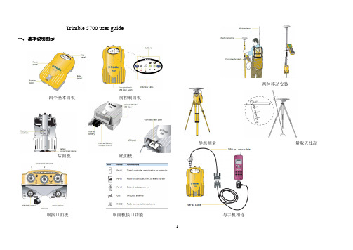
Trimble 5700 user guide 一、基本说明图示四个基本面板前控制面板后面板底面板顶接口面板顶面板接口功能两种移动安装静态测量量取天线高与手机相连二、基本操作1 谨慎操作:勿在电脑上格式化CF卡,应在接收机里格式化之——置卡于接收机内,长按电源按钮30秒。
2 前面板操作:前面板按钮与指示灯⑴开、关接收机:按下电源按钮,接收机处于“开”状态,按住电源按钮,2秒钟后LED灯全熄灭,放开按钮,接收机被关闭。
按下记录按钮,开始记录;按下记录按钮2秒钟,记录灯熄灭,停止记录。
⑵黄色的LED记录指示灯的几种状态:正常闪烁为每3秒闪一次。
开:数据被存入;慢闪:足够的静态数据被存入。
如果红色的SV Tracking LED长亮,并且其它LED 不亮,表明接收机处于监视模式,关闭电源并重开,即进入正常操作状态。
快闪:数据被存入,但内在较少。
更慢闪:接收机处于休眠模式,定时应用文件开始前5分钟将唤醒接收机。
关:数据没记录。
⑶红色卫星跟踪LED指示灯的几种状态:正常闪烁为每3秒闪一次。
慢闪:索定4颗以上卫星;快闪:索定3颗以下卫星;关:无索定卫星;开:接收机处于监视状态,正在检查新固件并安装。
⑷绿色LED无线电指示灯:慢闪:收到一个数据包或事件标识。
⑸LED电池灯的状态如下表:⑸两种数据格式:*.t01含有GLONASS数据,*.dat只含有GPS数据,Trimble Business Center支持*.t01,而Trimble Geometic Office只支持*.dat。
三、数据传输接收机中的CF卡可容纳500多个文件,卡中文件必须为8.3格式,不支持文件扩展名。
数据传输可用的软件:Trimble Business Center software(*.t01), Trimble Data Transfer utility(*.dat).也可把CF卡直接从接收机取出装入电脑拷贝。
数据类型及传输软件:Trimble Geomatics Office不支持*.t01,因而,用TGO解算之前,必须将数据从*.t01转为*.dat,但转换后GLONASS数据随之丢失。
SMCIPMITool_User_Guide

SMCIPMITool User GuideRelease 1.0aDocument SMCIPMITool_Guide_1.0aSuper Micro IPMITool User GuideRelease: 1.0aDocument: SMICIPMITool_Guide_1.0aDocument status: StandardDocument release date: 1/28/2011Copyright © 2011 Super MicroAll Rights Reserved.This document is protected by copyright laws and international treaties. All information, copyrights and any other intellectual property rights contained in this document are the property of Super Micro. Except as expressly authorized in writing by Super Micro, the holder is granted no rights to use the information contained herein and this document shall not be published, copied, produced or reproduced, modified, translated, compiled, distributed, displayed or transmitted, in whole or part, in any form or media.Contents1 Introduction (10)1.1 Purpose (10)1.2 Set Up (10)1.3 Key Conventions (11)1.3.1 Keyboard Shortcuts (11)1.4 Third Party Software (11)1.4.1 JLine (11)2 Usage and Command (11)2.2 Document Conventions (12)3 Commands (12)3.1 system (12)3.2 failure (14)3.3 blade (14)3.3.1 blade status (14)3.3.2 blade index(es) (15)3.3.2.1 status (15)3.3.2.2 power (16)3.3.2.3 kvm (16)3.3.2.4 uid (16)3.3.2.5 sensor (16)3.3.2.6 bmc (17)3.3.2.6.1 ip (17)3.3.2.6.2 dhcp (17)3.3.2.6.3 vlan (17)3.3.2.6.4 ipmb (17)3.3.2.7 config (17)3.4 gigabit (18)3.4.1 gigabit status (18)3.4.2 gigabit index(es) (18)3.4.2.1 status (18)3.4.2.2 power (19)3.4.2.3.1 ip (19)3.4.2.3.2 netmask (19)3.4.2.3.3 gateway (19)3.4.2.3.4 datetime (19)3.4.2.3.5 username (19)3.4.2.3.6 password (19)3.4.2.4 ipmode (20)3.4.2.5 boot (20)3.4.2.6 restart (20)3.4.2.7 fd (20)3.5 power (20)3.5.1 power status (20)3.5.2 power index(es) (21)3.5.2.1 status (21)3.5.2.2 power (21)3.5.2.3 fan (21)3.6 ib (21)3.6.1 ib status (21)3.6.2 ib index(es) (22)3.6.2.1 status (22)3.6.2.2 power (22)3.7 cmm (22)3.7.1 cmm status (22)3.7.2 cmm index (23)3.7.2.1 status (23)3.7.2.2 dtime (23)3.7.2.3 ntp (23)3.7.2.4 reset (23)3.7.2.5 flash (23)3.7.2.6 ver (24)3.7.2.7 ip (24)3.7.2.9 gateway (24)3.7.2.10 netmask (24)3.7.2.11 syncfg (24)3.7.2.12 opmode (24)3.7.2.13 dhcp (25)3.8 listtemp (25)3.9 sel (27)3.9.1 info (27)3.9.2 list (27)3.9.3 csv (27)3.9.4 clear (27)3.10 allsel (28)3.11 user (28)3.11.1 add (28)3.11.2 list (28)3.11.3 delete (28)3.11.4 level (28)3.11.5 test (29)3.12 vm (29)3.12.1 status (29)3.12.2 stop (29)3.12.3 floppy (30)3.12.4 iso (30)3.13 ipmi (30)3.13.1 sensor (30)3.13.2 power (31)3.13.2.1 up (32)3.13.2.2 down (32)3.13.2.3 softshutdown (32)3.13.2.4 reset (32)3.13.2.5 cycle (32)3.13.3 acpi (32)3.13.4 lan (32)3.13.4.1 ip (32)3.13.4.2 mac (33)3.13.4.3 gateway (33)3.13.4.4 netmask (33)3.13.4.5 snmp (33)3.13.4.6 snmpcomm (34)3.13.4.7 arp (34)3.13.4.8 dhcp (34)3.13.4.9 vlan (34)3.13.5 fru (34)3.13.6 oem (35)3.13.6.1 clrint (35)3.13.6.2 id (35)3.13.6.3 uid (35)3.13.6.4 backup (35)3.13.6.5 restore (35)3.13.6.6 lani (36)3.13.7 reset (36)3.13.8 ver (36)3.13.9 flash (36)3.13.10 flashw (36)3.13.11 raw (36)3.13.12 ipmb (37)3.13.13 ipmboem (37)3.13.14 delsdr (37)3.14 shell (37)3.15 ver (38)3.16 ch (38)3.17 list (38)3.19 found (38)3.20 exec (38)3.21 host (39)3.21.1 list (39)3.21.2 reload (39)3.21.3 add (40)3.21.4 remove (40)3.21.5 rename (40)3.21.6 group (40)3.21.6.1 add (40)3.21.6.2 remove (40)3.21.6.3 rename (40)3.21.6.4 addhost (40)3.21.6.5 removehost (40)3.22 hostrun (41)3.23 sc (41)3.24 pminfo (41)3.25 nm (43)3.25.1 detect (43)3.25.2 ver (43)3.25.3 cap (43)3.25.4 status (44)3.25.5 stat (44)3.25.6 resetStat (44)3.25.7 pstate (44)3.25.8 tstate (45)3.25.9 ptstate (45)3.25.10 alert (45)3.25.11 scanPolicy (46)3.25.12 addPolicy (47)3.25.13 delPolicy (47)3.25.15 enablePolicy (47)3.25.16 disablePolicy (48)3.26 deploy (48)3.26.1 one (48)3.26.2 all (48)3.26.3 check (48)3.26.4 status (48)3.26.5 clear (48)3.27 kvmwa (48)3.28 ukvm (49)3.29 vmwa (49)3.29.1 dev1list (49)3.29.2 dev1drv (49)3.29.3 dev1stop (49)3.29.4 dev2list (49)3.29.5 dev2cd (50)3.29.6 dev2iso (50)3.29.7 dev2stop (50)3.29.8 allstatus (50)3.29.9 status (50)3.29.10 log (50)3.30 dcmi (50)3.30.1 find (50)3.30.2 cap (51)3.31 dr (52)3.31.1 list (53)3.31.2 iso (53)3.31.3 drv (53)3.32 kvm (54)3.33 kvmw (54)3.34 vmw (54)3.34.2 vmw usbkey (54)3.34.3 vmw iso (54)3.34.4 vmw cd (54)3.34.5 vmw stopFloppy (54)3.34.6 vmw stopUsbkey (55)3.34.7 vmw stopISO (55)3.34.8 vmw stopCD (55)3.34.9 vmw status (55)3.35 sol (55)3.35.1 sol activate (55)3.35.2 sol deactivate (55)3.35.3 sol window (56)3.35.4 sol key (56)3.35.5 bitrate (56)Appendix A Command Categories (57)Appendix B VM Command Examples (59)B.1 AMI IPMI Firmware (59)B.2 ATEN IPMI Firmware (60)B.3 Peppercon IPMI Firmware (63)Appendix C Trap Receiver (66)1 Introduction1.1 PurposeIPMI (Intelligent Platform Management Interface) is an Intel-defined standard to allow a user to interface with a computer system to monitor the health of and manage the system.The SMCIPMITool is a Supermicro utility that allows a user to interface with SuperBlade systems and IPMI devices via a CLI (Command Line Interface).1.2 Set UpThis utility requires Sun JRE 1.5.x or above. Please install Java on your platform in advance of initiating SMCIPMITool. To download, please go to the following link:/javase/downloads/index.jspThere are two executable files in the SMCIPMITool utility:∙SMCIPMITool.jar: A jar file only.∙SMCIPMITool.exe : A windows executable wrapper for SMCIPMITool.jarUsers can choose either the jar or a native executable file. For Linux environments, an extra setting to the environment is required, as shown below.Add jre to your PATH line in the .bashrc file: PATH=/usr/java/jre1.5.0_12/bin:$PATHThe "jre1.5.0_12" folder may change depending on your version of Java.1.3 Key Conventions1.3.1 Keyboard Shortcuts1.4 Third Party Software1.4.1 JLineSMCIPMITool uses JLine for command history and tab-completion. JLine is a Java library used to handle console input and is similar in functionality to BSD editline and GNU readline. People familiar with the readline/editline capabilities for modern shells (such as bash and tcsh) will find most of the command editing features of JLine to be familiar.Please refer to /index.html for more information.2 Usage and CommandEnter the console mode and run the following command to start (online help is included): Usage:java -jar SMCIPMITool.jar <IP> <username> <password> [commands ... ]orSMCIPMITool <IP> <username> <password> [commands ... ]2.2 Document Conventions∙The syntax of the CLI command is given in Courier New 11 bold.∙Elements in (< >) indicate the field required as input along with a CLI command, for example < integer (100-1000)>.∙Elements in square brackets ([ ]) indicate optional fields for a command.∙Both “ * “ and “ , ” may be used to specify the numbers for the blade/gigabit/power/ib index(es) commands. For example:CMM> blade 1,2,3 statusCMM> gigabit * status3 CommandsThis section lists the commands available with SMCIPMITool. You must follow the usage protocol as described in the previous section.3.1 systemThe system command displays the system information. In a blade system, this command will also list the modules present (CMM modules, Gb switches, power supplies, etc.).Usage: systemExample Output:Blade Module (20/20)--------------------Blade | Power | KVM | UID | Error | BMC | Watt | MB----- | ----- | --- | --- | ----- | --- | ---- | --Blade 1 | Off | Selected | | | Yes | 350W | B8DTTBlade 2 | Off | | | | Yes | 400W | B8DTTBlade 3 | On | | | | Yes | 350W | B8DTTBlade 4 | On | | | | Yes | 350W | B8DTTBlade 5 | On | | | | Yes | 350W | B8DTTBlade 6 | On | | | | Yes | 350W | B8DTTBlade 7 | On | | | | Yes | 350W | B8DTTBlade 8 | On | | | | Yes | 350W | B8DTTBlade 9 | On | | | | Yes | 350W | B8DTTBlade 10 | On | | | | Yes | 350W | B8DTTBlade 11 | Off | | | | Yes | 400W | B8DTTBlade 12 | Off | | | | Yes | 400W | B8DTTBlade 13 | On | | | | Yes | 350W | B8DTTBlade 14 | On | | | | Yes | 350W | B8DTTBlade 15 | On | | | | Yes | 350W | B8DTTBlade 16 | On | | | | Yes | 350W | B8DTTBlade 17 | On | | | | Yes | 350W | B8DTTBlade 18 | On | | | | Yes | 350W | B8DTTBlade 19 | On | | | | Yes | 350W | B8DTTBlade 20 | On | | | | Yes | 350W | B8DTTGigabit Switch Module (1/2)------------------------GBSW | Power | Error | Init | Switch | 2.5V | 1.25V | Type---- | ----- | ----- | ---- | ------ | ---- | ----- | ----------GBSW 1 | On | | Not | 61C/142F | 2.48V | 1.192V | L3 SwitchPower Supply Module (4/4)--------------------------PS | Power | Fan 1 | Fan 2 | Temp. | Watts | DC | AC | F/W | FRU -- | ----- | ----- | ----- | ----- | ----- | -- | -- | --- | --- PS 1 | On | 5152 | 5152 | 56C/133F | 2000 | N/A | N/A | 2.6 | 01 PS 2 | On | 5381 | 5381 | 54C/129F | 2000 | N/A | N/A | 2.6 | 01 PS 3 | On | 5267 | 5152 | 57C/135F | 2000 | N/A | N/A | 2.6 | 01 PS 4 | On | 7328 | 7099 | 54C/129F | 2000 | N/A | N/A | 2.6 | 01IBQDR Module (1/2)------------------------IBQDR | Power | Temp. Switch | Temp. Board | 3.3V | 1.25V----- | ----- | ------------ | ----------- | ---- | -----IBQDR 1 | On | 57C/135F | 56C/133F | 3.24V | 1.18VCMM Module(1/2)----------------CMM | M/S | Status--- | --- | ------CMM 1 | Master | OKCMM 1 is being managed now3.2 failureThe failure command brings up a failure report, which lists all failure messages from the system.Usage: failure3.3 bladeThe blade command will bring up the following subcommands.3.3.1 blade statusThis command will display the status of all the blade units in the system.Usage: blade statusExample Output:Blade Module (20/20)--------------------Blade | Power | KVM | UID | Error | BMC | Watt | MB----- | ----- | --- | --- | ----- | --- | ---- | --Blade 1 | Off | Selected | | | Yes | 350W | B8DTTBlade 2 | Off | | | | Yes | 400W | B8DTTBlade 3 | On | | | | Yes | 350W | B8DTTBlade 4 | On | | | | Yes | 350W | B8DTTBlade 5 | On | | | | Yes | 350W | B8DTTBlade 6 | On | | | | Yes | 350W | B8DTTBlade 7 | On | | | | Yes | 350W | B8DTTBlade 8 | On | | | | Yes | 350W | B8DTTBlade 9 | On | | | | Yes | 350W | B8DTTBlade 10 | On | | | | Yes | 350W | B8DTTBlade 11 | Off | | | | Yes | 400W | B8DTTBlade 12 | Off | | | | Yes | 400W | B8DTTBlade 13 | On | | | | Yes | 350W | B8DTTBlade 14 | On | | | | Yes | 350W | B8DTTBlade 15 | On | | | | Yes | 350W | B8DTTBlade 16 | On | | | | Yes | 350W | B8DTTBlade 17 | On | | | | Yes | 350W | B8DTTBlade 18 | On | | | | Yes | 350W | B8DTTBlade 19 | On | | | | Yes | 350W | B8DTTBlade 20 | On | | | | Yes | 350W | B8DTT3.3.2 blade index(es)This command is used to check the individual blades in the system. The following subcommands may be used for a specific blade.3.3.2.1 statusUsed to check the status of the individual blade specified.Usage: blade <blade number> statusExample Output:[ 1]:Blade | Power | KVM | UID | Error | BMC | Watt | MB----- | ----- | --- | --- | ----- | --- | ---- | --Blade 1 | Off | Selected | | | Yes | 350W | B8DTT[ 2]:Blade | Power | KVM | UID | Error | BMC | Watt | MB----- | ----- | --- | --- | ----- | --- | ---- | --Blade 2 | Off | | | | Yes | 400W | B8DTT3.3.2.2 powerUsed to access power control for the individual blade specified.Usage: blade <blade number> power [up|down|softshutdown|reset] Example Output:[ 1]:Power: OffAvailable commands: up, down, softshutdown, reset[ 2]:Power: OffAvailable commands: up, down, softshutdown, reset3.3.2.3 kvmRequests a kvm switch for the individual blade specified.Usage: blade <blade number> kvm3.3.2.4 uidUsed to turn a UID LED on or off as specified on an individual blade.Usage: blade <blade number> uid <on/off>3.3.2.5 sensorUsed to get sensor readings from the individual blade specified.Usage: blade <blade number> sensorExample Output:Status | Sensor | Reading | Low Limit | High Limit | ------ | ------ | ------- | --------- | ---------- | OK | CPU1 Temp | 1C/ 34F | N/A | 80C/176F | OK | CPU2 Temp | 1C/ 34F | N/A | 80C/176F | OK | System Temp | 64C/147F | N/A | 80C/176F | OK | CPU1 Vcore | 0.95 V | 0.6 V | 1.38 V |OK | CPU2 Vcore | 0.96 V | 0.6 V | 1.38 V |OK | CPU1 DIMM | 1.53 V | 1.2 V | 1.65 V |OK | CPU2 DIMM | 1.53 V | 1.2 V | 1.65 V |OK | 1.5V | 1.52 V | 1.34 V | 1.65 V |OK | 3.3V | 3.16 V | 2.96 V | 3.63 V |OK | 3.3VSB | 3.36 V | 2.96 V | 3.63 V |OK | 5V | 5.06 V | 4.49 V | 5.5 V |OK | 12V | 12.19 V | 10.75 V | 13.25 V |OK | VBAT | 3.36 V | 2.96 V | 3.63 V |3.3.2.6 bmcThis command will bring up the following subcommands related to the BMC of an individual blade.3.3.2.6.1 ipUsed to get or set the IP address of a blade’s BMC.Usage (to get): blade <blade number> bmc ipUsage (to set): blade <blade number> bmc ip <IP>3.3.2.6.2 dhcpUsed to enable or disable the DHCP (Dynamic Host Configuration Protocol) of a blade. Usage: blade <blade number> bmc dhcp [enable|disable]3.3.2.6.3 vlanUsed to display or enable or d isable an individual blade’s VLAN (Virtual LAN).Usage: blade <blade number> bmc vlan [<enable|disable> >tag>]3.3.2.6.4 ipmbUsed to send a raw IPMI command to an individual blade.Usage: blade <blade number> bmc ipmb <netFn> <cmd> [data]3.3.2.7 configUsed to get the configuration of the individual blade specified.Usage: blade <blade number> configExample Output:MB ID = BDPwr Consumption = 350WCPUs = 2CPU Type = undefinedCPU Speed = 2.90GhzDIMMs = 2Memory Size = 8192MBMemory Speed = 1066MhzLANs = 2LAN 1 MAC = 00:30:48:F7:65:CCLAN 2 MAC = 00:30:48:F7:65:CDMB SN = ????????????????3.4 gigabitEntering the gigabit command will bring up the following subcommands.3.4.1 gigabit statusThis command will display the status of all the Gb switch units in the system.Usage: gigabit statusExample Output:Gigabit Switch Module (1/2)------------------------GBSW | Power | Error | Init | Switch | 2.5V | 1.25V | Type---- | ----- | ----- | ---- | ------ | ---- | ----- | ----------GBSW 1 | On | | Not | 61C/142F | 2.496V | 1.192V | L3 Switch3.4.2 gigabit index(es)This command brings up the following commands related to an individual Gb switch in the system as specified.3.4.2.1 statusUsed to display the status of the gigabit switch specified.Usage: gigabit <gigabit number> statusExample Output:GBSW | Power | Error | Init | Switch | 2.5V | 1.25V | Type---- | ----- | ----- | ---- | ------ | ---- | ----- | ----------GBSW 1 | On | | Not | 61C/142F | 2.48V | 1.192V | L3 Switch3.4.2.2 powerUsed to access power control for the gigabit switch specified.Usage: gigabit <gigabit number> power <on|off|reset>3.4.2.3 wssUsed to access WSS (WebSuperSmart) web configuration control for the gigabit switch specified.3.4.2.3.1 ipUsed to get or set the IP address of a gigabit switch.Usage: gigabit <gigabit number> wss ip [IP]3.4.2.3.2 netmaskUsed to get or set the netmask address of a gigabit switch.Usage: gigabit <gigabit number> wss netmask [netmask]3.4.2.3.3 gatewayUsed to get or set the gateway address of a gigabit switch.Usage: gigabit <gigabit number> wss gateway [gateway]3.4.2.3.4 datetimeUsed to get or set the date and time settings for a gigabit switch.Usage: gigabit <gigabit number> wss datetime [datetime]Example Output:12/29/2010 02:56:023.4.2.3.5 usernameUsed to get or set the username of WSS web for a gigabit switch.Usage: gigabit <gigabit number> wss username [username]3.4.2.3.6 passwordUsed to get or set the password of WSS web for a gigabit switch.Usage: gigabit <gigabit number> wss password [password]3.4.2.4 ipmodeUsed to get or set the IP mode of the gigabit switch specified.Usage (to get): gigabit <gigabit number> ipmodeUsage (to set): gigabit <gigabit number> ipmode <mode>3.4.2.5 bootUsed to get or set the boot image of the gigabit switch specified.Usage: gigabit <gigabit number> boot [image number]3.4.2.6 restartUsed to soft restart the gigabit switch specified.Usage: gigabit <gigabit number> restart3.4.2.7 fdUsed to reset to factory default for the gigabit switch specified.Usage: gigabit <gigabit number> fd3.5 powerEntering the power command will bring up the following subcommands.3.5.1 power statusThis command will display the status of all the power supply units in the blade system.Usage: power statusExample Output:Power Supply Module (4/4)--------------------------PS | Power | Fan 1 | Fan 2 | Temp. | Watts | DC | AC | F/W | FRU -- | ----- | ----- | ----- | ----- | ----- | -- | -- | --- | --- PS 1 | On | 5152 | 5152 | 57C/135F | 2000 | N/A | N/A | 2.6 | 01 PS 2 | On | 5381 | 5381 | 54C/129F | 2000 | N/A | N/A | 2.6 | 01 PS 3 | On | 5152 | 5152 | 58C/136F | 2000 | N/A | N/A | 2.6 | 01 PS 4 | On | 7328 | 7213 | 54C/129F | 2000 | N/A | N/A | 2.6 | 013.5.2 power index(es)This command is used to check the individual power supplies in the blade system and brings up the following commands:3.5.2.1 statusUsed to display the status of the power supply specified.Usage: power <power number> statusExample Output:PS | Power | Fan 1 | Fan 2 | Temp. | Watts | DC | AC | F/W | FRU -- | ----- | ----- | ----- | ----- | ----- | -- | -- | --- | --- PS 1 | On | 5152 | 5152 | 56C/133F | 2000 | N/A | N/A | 2.6 | 013.5.2.2 powerUsed to access power control for the power supply specified.Usage: power <power number> <on|off>3.5.2.3 fanUsed to access fan control for the power supply specified.Usage: power <power number> fan <1|2|3|4|auto>3.6 ibEntering the ib command will bring up the following subcommands.3.6.1 ib statusThis command will display the status of all the InfiniBand switches in the system.Usage: ib statusExample Output:IBQDR Module (1/2)------------------------IBQDR | Power | Temp. Switch | Temp. Board | 3.3V | 1.25V----- | ----- | ------------ | ----------- | ---- | -----IBQDR 1 | On | 57C/135F | 56C/133F | 3.24V | 1.18V3.6.2 ib index(es)This command is used to check the individual InfiniBand switches in the system and will bring up the following subcommands:3.6.2.1 statusUsed to display the status of the InfiniBand switch specified.Usage: ib <ib number> statusExample Output:IB | Power | Init | VVDD | 3.3V Aux | 1.2V | 1.8V | 3.3V | Temp.-- | ----- | ---- | ---- | -------- | ---- | ---- | ---- | -----IB 1 | Off | OK | 1.92V | 2.85V | 0.78V | 1.48V | 2.85V | 0C/32F3.6.2.2 powerUsed to access power control for the InfiniBand switch specified.Usage: ib <ib number> power <on|off|reset>3.7 cmmEntering the cmm command will bring up the following subcommands.3.7.1 cmm statusThis command will display the status of all the CMM in the system.Usage: cmm statusExample Output:CMM Module(1/2)----------------CMM | M/S | Status--- | --- | ------CMM 1 | Master | OKCMM 1 is being managed nowCMM IP address:---------------CMM 1 IP: 172.31.100.2353.7.2 cmm indexThis command is used to check the individual CMM in the system and will bring up the following subcommands:3.7.2.1 statusUsed to display the status of the CMM specified.Usage: cmm <cmm number> statusExample Output:CMM | M/S | Status--- | --- | ------CMM 1 | Master | OKCMM 1 is being managed now3.7.2.2 dtimeUsed to get or set CMM date and time.Usage: cmm <cmm number> dtime [datetime]Example Output:12/29/2010 02:56:02(Data time format for setting: "MM/dd/yyyy HH:mm:ss")3.7.2.3 ntpUsed to synch the time with the NTP servers.Usage: cmm <cmm number> ntp <UTC offset> <NTP1> [NTP2]3.7.2.4 resetUsed to reset the CMM specified.Usage: cmm <cmm number> reset3.7.2.5 flashUsed to flash CMM firmware to the CMM specified with the filename of the flash upgrade noted..Usage: cmm <cmm number> flash <filename>3.7.2.6 verUsed to display the firmware version in the CMM specified. Usage: cmm verExample Output:Version:2.2.64 build 54203.7.2.7 ipUsed to get or set the IP address of the CMM specified. Usage: cmm <cmm number> ip [IP address]IP address format: ###.###.###.###3.7.2.8 macUsed to get or set the MAC address of the CMM specified. Usage: cmm <cmm number> mac [mac address]MAC address format: ###.###.###.###3.7.2.9 gatewayUsed to get or set the Gateway address of the CMM specified. Usage: cmm <cmm number> gateway [gateway address] Gateway address format: ###.###.###.###3.7.2.10 netmaskUsed to get or set the Netmask IP address of the CMM specified. Usage: cmm <cmm number> netmask [netmask address] Netmask address format: ###.###.###.###3.7.2.11 syncfgUsed to sych the configuration to the slave CMM specified.3.7.2.12 opmodeUsed to get or set the operational mode for the CMM specified. Usage: cmm <cmm number> opmode [mode]Mode Choices: 0 = Enterprise 1 = Office3.7.2.13 dhcpUsed to enable or disable the DHCP (Dynamic Host Configuration Protocol) of the CMM.Usage: cmm <cmm number> dhcp [enable|disable]3.8 listtempEntering the listtemp command will display the temperatures of all the modules in the blade system.Usage: listtempExample Output:Status | Module | Sensor | Reading | High Limit |------ | ------ | ------ | ------- | ---------- |OK | Blade 3 | CPU1 Temp | Low | N/A |OK | Blade 3 | CPU2 Temp | Low | N/A |OK | Blade 3 | System Temp | 56C/133F | 80C/176F |OK | Blade 4 | CPU1 Temp | Low | N/A |OK | Blade 4 | CPU2 Temp | Low | N/A |OK | Blade 4 | System Temp | 57C/135F | 80C/176F |OK | Blade 5 | CPU1 Temp | Low | N/A |OK | Blade 5 | CPU2 Temp | Low | N/A |OK | Blade 5 | System Temp | 63C/145F | 80C/176F |OK | Blade 6 | CPU1 Temp | Low | N/A |OK | Blade 6 | CPU2 Temp | Low | N/A |OK | Blade 6 | System Temp | 64C/147F | 80C/176F |OK | Blade 7 | CPU1 Temp | Medium | N/A |OK | Blade 7 | CPU2 Temp | Low | N/A |OK | Blade 7 | System Temp | 62C/144F | 80C/176F |OK | Blade 8 | CPU1 Temp | Low | N/A |OK | Blade 8 | CPU2 Temp | Low | N/A |OK | Blade 8 | System Temp | 63C/145F | 80C/176F |OK | Blade 9 | CPU1 Temp | Medium | N/A |OK | Blade 9 | CPU2 Temp | Low | N/A | OK | Blade 9 | System Temp | 62C/144F | 80C/176F | | Blade 10 | CPU1 Temp | N/A | N/A | OK | Blade 10 | CPU2 Temp | Low | N/A | OK | Blade 10 | System Temp | 59C/138F | 80C/176F | OK | Blade 13 | CPU1 Temp | Low | N/A | OK | Blade 13 | CPU2 Temp | Low | N/A | OK | Blade 13 | System Temp | 60C/140F | 80C/176F | OK | Blade 14 | CPU1 Temp | Low | N/A | OK | Blade 14 | CPU2 Temp | Low | N/A | OK | Blade 14 | System Temp | 60C/140F | 80C/176F | OK | Blade 15 | CPU1 Temp | Medium | N/A | OK | Blade 15 | CPU2 Temp | Low | N/A | OK | Blade 15 | System Temp | 63C/145F | 80C/176F | OK | Blade 16 | CPU1 Temp | Low | N/A | OK | Blade 16 | CPU2 Temp | Low | N/A | OK | Blade 16 | System Temp | 61C/142F | 80C/176F | OK | Blade 17 | CPU1 Temp | Low | N/A | OK | Blade 17 | CPU2 Temp | Low | N/A | OK | Blade 17 | System Temp | 63C/145F | 80C/176F | OK | Blade 18 | CPU1 Temp | Medium | N/A | OK | Blade 18 | CPU2 Temp | Medium | N/A | OK | Blade 18 | System Temp | 65C/149F | 80C/176F | OK | Blade 19 | CPU1 Temp | Low | N/A | OK | Blade 19 | CPU2 Temp | Medium | N/A | OK | Blade 19 | System Temp | 62C/144F | 80C/176F | | Blade 20 | CPU1 Temp | N/A | N/A | OK | Blade 20 | CPU2 Temp | Low | N/A | OK | Blade 20 | System Temp | 62C/144F | 80C/176F | OK | Power 1 | Temp. | 56C/133F | 85C/185F |OK | Power 2 | Temp. | 54C/129F | 85C/185F |OK | Power 3 | Temp. | 57C/135F | 85C/185F |OK | Power 4 | Temp. | 54C/129F | 85C/185F |OK | GBSW 1 | Switch | 61C/142F | 80C/176F |OK | InfiniBand 1 | Temp. | 0C/ 32F | 80C/176F |3.9 selEntering the sel command will bring up the following subcommands for the system event log.3.9.1 infoThis command gives the information on the system event log.Usage: sel infoExample Output:Total Entries: 2SEL Version: 1.5Free Space: 9180bytesRecent Entry Added: 12/20/2010 22:37:33Recent Entry Erased: Pre-Init 00:00:003.9.2 listThis command will display the list of entries to the system event log.Usage: sel list3.9.3 csvThis subcommand will save the system event log as a csv file with the name specified in the filename.Usage: sel csv <filename>3.9.4 clearThis command will clear the system event log.Usage: sel clear3.10 allselEntering the allsel command will save all blade system event logs as a csv file with the name specified in the filename.Usage: allsel <filename>3.11 userEntering the user command will list the following user management subcommands.3.11.1 addUse this command to enter the name of a new user.Usage: user add <user ID> <user name> <password> <privilege>3.11.2 listEntering the list command will display the users.Usage: user listExample Output:Maximum number of Users : 10Count of currently enabled Users : 2User ID | User Name | Privilege Level | Enable------- | --------- | --------------- | ------2 | ADMIN | Administrator | Yes3.11.3 deleteEntering the delete command allows you to delete a user.Usage: user delete <user ID>3.11.4 levelEntering the level command allows you to update the level of a user.Usage: user level <user ID> <privilege>The following levels may be assigned:4: Administrator level∙3: Operator level∙2: User level∙1: Callback3.11.5 testEntering the test command allows you to test logging in as a specific user.Usage: user test <user ID> <password>3.12 vmEntering the vm command will list the following virtual media management subcommands. Refer to Appendix B for more on VM commands.3.12.1 statusUsing the status command lists the status of the drives present in the system.Usage: vm statusExample Output:Drive 1Device Status = CD-ROM image on Windows share setImage Size = 522766336 (bytes)Access Mode = Read-OnlyImage source = //192.168.10.43/iso/cd1.isoDrive 2Device Status = CD-ROM image on Windows share setImage Size = 522766336 (byte)Access Mode = Read-OnlyImage source = //192.168.10.43/iso/cd2.iso3.12.2 stopUsing the stop command allows you to stop the specified drive.Usage: vm stop <drive ID>。
IMM User Guide

IMM使用指南一.如何访问IMM (1)二.IMM主要功能介绍 (4)三.几个常用功能 (5)1.远程开关机 (5)2.通过IMM刷新服务器的UEFI/IMM微码 (6)3.远程终端功能 (7)一.如何访问IMM通常主机后部有一个专用的管理端口,例如下图以3650M3为例,可以通过此端口访问IMM。
IMM管理端口默认IP:192.168.70.125用户名:USERID密码:PASSW0RD注意字母为大写,密码中的“0”是数字0在UEFI中修改IMM的IP地址在开机自检的过程中根据提示按F1进入UEFI设置,输入需要修改的IP地址后,选择Save Network Settings在IE中输入IP地址即可访问IMM管理界面二.IMM主要功能介绍System status查看服务器的健康状况,包括温度、电压和风扇状态等。
Virtual Light Path查看服务器光通路诊断板上是否有告警。
Event Log可以查看服务器的日志信息,可以用Save Log as Text File另存日志信息为文本文件。
Vital Product Data查看服务器的型号序列号及各种微码版本。
Power/Restart通过IMM控制开关服务器,包括定时开关机功能Remote Control远程控制服务器终端,需要添加IBM Virtual Media Key选件来实现此功能,大部分机型标配没有此选件。
PXE Network Boot设置服务器的PXE启动。
Firmware Update刷新服务器的UEFI和IMM的微码。
System Settings设置IMM的时间日期,名字等基本信息。
Login Profiles为IMM添加除默认之外的其他用户。
Alerts设置snmp告警等信息。
Serial Port设置串口信息Port assignments定义IMM所使用的端口。
Network Interfaces设置IMM的网络地址Network Protocols配置SNMP,DNS等网络协议Security配置SSL、SSH等安全协议Configuration File备份和恢复IMM的配置文件Restore Default Settings将IMM恢复默认设置Restrat IMM重启IMMLog off退出登录三.几个常用功能1.远程开关机选择Power/Restart选项可以实现远程开机、关机和重启在Schedule Daily/Weekly Power and Restart Actions中可以实现每天定时的开关服务器。
信息机房环境监控系统RDUM使用操作说明
信息机房环境监控系统RDUM使用操作说明信息机房环境监控系统RDUM使用操作说明为了保障信息机房内的设备能够正常运行,防止设备受到损失,对信息机房环境的监测必不可少。
信息机房环境监控系统RDUM是一种智能化环境监测系统,它能够实时监测信息机房内的温度、湿度、氧气含量、空气流量和漏水情况等关键环境指标,以保障信息机房内的设备运行安全。
本文将介绍如何使用信息机房环境监控系统RDUM。
一、安装与设置1.系统安装RDUM内置在服务器中,只需要在机房安装好服务器即可。
如果需要设置远程访问,需要开启相关端口访问权限。
2.系统设置打开系统后需要进行一些基础设置,如设置系统语言、时区、密码等。
二、监控界面1.登录系统启动浏览器,在地址栏输入RDUM服务器地址。
在登录界面中输入用户名和密码,登录后即可进入监控界面。
2.监控界面进入监控界面后,可以看到两个主要区域:左侧为设备树,右侧为监控画面。
设备树列出了所有监测设备的名称和位置,并且提供了设备的具体信息和运行状态。
监控画面显示了所选设备的监测数据、实时曲线和告警信息。
三、监测数据1.温度温度监测是信息机房环境监控系统RDUM最基本的功能之一。
在监控界面中,通过选择相应的设备,在画面上即可看到实时温度值。
在温度测量值过高或过低时,系统会自动发出警报以及报警信息。
2.湿度信息机房环境监控系统RDUM还能够检测相对湿度。
只需选择相应的设备,在监控画面上即可看到实时湿度值。
如湿度超过设定的阈值(一般落在30%和60%之间),系统也将自动发出警报以及报警信息。
3.氧气含量放置在机房中的RDUM系统可以检测无毒气体污染的存在。
如果存在潜在的氧气污染,系统将通过警报和危险标志来表示这种情况。
4.空气流量RDUM系统还可以检测机房中空气流量。
在监控画面中选择相应的设备即可查看实时数据。
如空气流量有异常,则会自动发出警报以及报警信息。
5.漏水在机房中,漏水是一种常见的情况。
RDUM系统可以检测机房中的漏水情况。
华为LTE后台操作指导书

LTE后台操作指导书目录一、常用指令:2二、提取CHR文档:9三、制作批处理脚本文档103.1加扰测试脚本:103.2日常告警全网TDL&TDS基站状态&告警查询-XXXX脚本113.3基站小区去激活脚本113.4基站小区邻区数据修改脚本12四、集中任务管理平安操作:134.1日常告警全网TDL&TDS基站状态&告警查询134.2基站小区去激活154.3基站小区邻区数据修改16五、LTE常用信令〔问题〕跟踪Check List V1.0165.1 端到端虚用户跟踪165.2 CELL DT175.3 IFTS195.4 一键式日志〔BRDLOG〕采集方法225.5 接入类问题分析数据235.6 切换类问题分析数据235.7 业务性能问题分析数据235.8 干扰问题分析数据24六、经历总结错误!未定义书签。
6.1XXLTE-FTP效劳器操作指导书-朱占磊(hw)错误!未定义书签。
6.2 LTE站点天线权值添加指引-X海春错误!未定义书签。
6.3 LTE站点在集中任务管理模块实现小区级批处理操作-林界滨错误!未定义书签。
6.4 LTE KPI指标监控日报撰写-李XX错误!未定义书签。
6.5 LTE虚用户跟踪流程及本卷须知-马志磊错误!未定义书签。
6.6 LTE灌包操作及问题定位指导-余世坛错误!未定义书签。
一、常用指令:TDL站点状态查询指令:LST CELL:; 查询小区静态参数DSP CELL:; 查询小区动态参数LST ALMAF:; 查询当前告警LST BFANT:;查询天线配置信息〔静态〕DSP BFANT:;查询天线配置信息〔动态〕LST PDSCHCFG:;(参考信号功率)LST CELLPDCCHALGO:;〔公共控制信令聚集级别〕LST CELLDLPCPDSCHPA:;〔pdsch功率控制PA调整开关〕LST EUTRANINTRAFREQNCELL:; 〔查询EUTRAN同频邻区关系〕LST EUTRANEXTERNALCELL:; 〔查询EUTRAN外部小区〕LST GPS:; 〔查询小区的经纬度〕LST ALMLOG:ALMTP=ALL;〔〕DSP CELLUET:;〔查询小区终端接入统计信息〕DSP BRDMFRINFO:;查询RRU型号LST ENODEBALGOSWITCH:;〔GERAN SRVCC开关〕LST CELLSTANDARDQCI:;(查询小区标准QCI参数)LST INTERRATHOMGROUP:;〔查询异系统切换公共参数组〕LST OPERATORHOCFG:;〔GERAN A2 RSRP门限偏置,这个现网大多数设置为-8〕本系统A2实际门限=异系统A2 RSRP触发门限+GERAN A2 RSRP门限配置-InterRatHoA1A2Hyst激活/解闭塞小区:ACT CELL:LOCALCELLID=1;ACT CELL:LOCALCELLID=2;ACT CELL:LOCALCELLID=3;UBL CELL:LOCALCELLID=1;UBL CELL:LOCALCELLID=2;UBL CELL:LOCALCELLID=3;去激活/闭塞小区:DEA CELL:LOCALCELLID=1;DEA CELL:LOCALCELLID=2;DEA CELL:LOCALCELLID=3;BLK CELL:LOCALCELLID=1,CELLADMINSTATE=CELL_HIGH_BLOCK;BLK CELL:LOCALCELLID=2,CELLADMINSTATE=CELL_HIGH_BLOCK;BLK CELL:LOCALCELLID=3,CELLADMINSTATE=CELL_HIGH_BLOCK;闭塞/解闭塞RRUBLK BRD:=0,SRN=200,SN=0,BLKTP=IMMEDIATE;UBL BRD:=0,SRN=202,SN=0;修改RRU通道:DSP TXBRANCH:;〔发射通道硬件最大输出功率、驻波比等,或:DSP VSWR:查询驻波比〕DSP RXBRANCH:;〔接收通道状态〕MOD TXBRANCH:=0,SRN=202,SN=0,TXNO=1,TXSW=OFF;(关)MOD TXBRANCH:=0,SRN=202,SN=0,TXNO=1,TXSW=ON; (开)MOD RXBRANCH:=0,SRN=202,SN=0,RXNO=1,RXSW=OFF; (关)MOD RXBRANCH:=0,SRN=202,SN=0,RXNO=1,RXSW=ON; (开)修改基站小区PCI:(注:同时要求修改邻区数据库相应的小区的PCI,不然影响切换) MOD CELL:LOCALCELLID=3,PHYCELLID=131;MOD CELL:LOCALCELLID=2,PHYCELLID=132;MOD CELL:LOCALCELLID=1,PHYCELLID=133;MODEUTRANEXTERNALCELL:MCC="460",MNC="08",ENODEBID=10072,CELLID=3,P HYCELLID=131;MODEUTRANEXTERNALCELL:MCC="460",MNC="08",ENODEBID=10072,CELLID=2,P HYCELLID=132;MODEUTRANEXTERNALCELL:MCC="460",MNC="08",ENODEBID=10072,CELLID=3,PHYCELLID=133;单验报告需要操作的内容:LST CELL:;LST PDSCHCFG:;LST CELLPDCCHALGO:;LST CELLDLPCPDSCHPA:;DSP CELL:;DSP LICENSE:;LST LICENSE:;LST CELLALGOSWITCH:;LST BFMIMOADAPTIVEPARACFG:;LST MIMOADAPTIVEPARACFG:;LTE加天线权值:LST BFANT:;DSP BFANT:;RMV BFANT: DEVICENO=0;RMV BFANT: DEVICENO=1;RMV BFANT: DEVICENO=2;DLDBFANTDB:IP="188.2.31.4",USR="ftpuser",PWD="Changeme_123",SRCF="ODS-090R15 NT.xml";DLDBFANTDB:IP="10.201.127.83",USR="ftpuser",PWD="ftpuser",SRCF="ODS-090R15NT.x ml";ACT BFANTDB:OPMODE=DLDFILE;ADDBFANT:DEVICENO=0,CONNSRN=60,MODELNO="ODS-09OR15NT",TILT=3,BEA MWIDTH=65,BAND=39;ADDBFANT:DEVICENO=1,CONNSRN=62,MODELNO="ODS-09OR15NT",TILT=3,BEA MWIDTH=65,BAND=39;ADDBFANT:DEVICENO=2,CONNSRN=82,MODELNO="ODS-09OR15NT",TILT=3,BEA MWIDTH=65,BAND=39;LST BFANT:;DSP BFANT:;查询BF开关:LST CELLALGOSWITCHTM2\3 BF:关TM2\3\7 BF:开修改BF算法开关:修改BF开关为开:MOD CELLALGOSWITCH:LOCALCELLID=1〔小区号〕,BFALGOSWITCH=BfSwitch-1;修改BF开关为关:MOD CELLALGOSWITCH:LOCALCELLID=1〔小区号〕,BFALGOSWITCH=BfSwitch-0; 修改基站〔业务信道〕加扰〔0~9〕:(模已)ADD CELLSIMULOAD:LOCALCELLID=1,SIMLOADCFGINDEX=7〔加扰为80%〕; ADD CELLSIMULOAD:LOCALCELLID=2,SIMLOADCFGINDEX=7;ADD CELLSIMULOAD:LOCALCELLID=3,SIMLOADCFGINDEX=7;RMV CELLSIMULOAD:LOCALCELLID=1;〔去加扰〕RMV CELLSIMULOAD:LOCALCELLID=2;RMV CELLSIMULOAD:LOCALCELLID=3;相关脚本:〔注意:百站网的本地小区ID是0、1、2〕所以在百站网执行脚本需改一下以下的LOCALCELLID加扰50%:ADD CELLSIMULOAD:LOCALCELLID=1; 〔SIMLOADCFGINDEX=4为默认值〕ADD CELLSIMULOAD:LOCALCELLID=2;ADD CELLSIMULOAD:LOCALCELLID=3;去加扰:RMV CELLSIMULOAD:LOCALCELLID=1;RMV CELLSIMULOAD:LOCALCELLID=2;RMV CELLSIMULOAD:LOCALCELLID=3;加扰100%ADD CELLSIMULOAD,然后配置索引那里填9就可以了。
D-LTE产品维护手册-华为

对比/互换
• 对比/互换可以帮助用户判断故障的范围或位置。 • 对比是指将故障的部件或现象与正常的部件或现象进行比较分析,查出不同点,找出问 • 题的所在。互换是指将处于正常状态的部件与可能故障的部件对调,比较对调前后二者 • 运行状况的变化,以此判断故障的范围或位置。 • 对比一般适用于故障范围单一的场景,互换一般适用于故障范围复杂的场景。
• 倒换/复位
倒换用于确定主用设备是否异常或者主备用关系是否协调;复位主要用于排除软件运行 异常。
Page13
用户跟踪
• 用户跟踪基于用户号码,可以按照发生时序完整的跟踪用户的标准接口、内部接口消 • 息、内部状态信息,并显示在屏幕上。 • 用户跟踪的优点如下: • l 实时性强,可以即时看到跟踪结果 • l 内容丰富,可以跟踪所有标准接口 • l 大话务量情况下可以使用 • l 应用场景广泛,可用于分析呼叫流程、VIP 客户跟踪等 • 用户跟踪定位手段经常用于定位能重现的呼叫类问题。
处理小区类故障
小区不可用故障是在当基站检测到 小区激活失败导致小区业务不可用 时,产生此告警。
Page18
处理IP 传输类故障
IP 传输故障是指通信的设备之间无 法正常交互报文、业务不通,并且 无法Ping 通对端 设备。
Page19
1. 基站操作维护常用命令 2. 故障处理流程和方法 3. LMT介绍及使用 4. 例行维护指南
l 相比其他方法而言,倒换/复位只能作为定位故障的一种辅助手段。 l 由于软件运行的随机性,倒换/复位后故障现象一般难以在短期内重现,从而容易 掩盖故障的本质,给设备的安全、稳定运行带来隐患。 l 复位操作会中断系统业务,甚至可能由于操作不慎而导致系统瘫痪,给系统的日常 运营带来严重的影响。
VDP_5_1_Admin_Guide_CN管理员中文手册

7 vSphere Data Protection 灾难恢复 49
索引 51
4
VMware, Inc.
关于本指南
《vSphere Data Protection 管理指南》包含安装和管理适用于中小型企业的备份的信息。
适用对象
本指南适用于任何希望使用 vSphere Data Protection 提供备份解决方案的用户。本指南中的信息适用于熟悉虚 拟机技术和数据中心操作的经验丰富的 Windows 或 Linux 系统管理员。
VMware, Inc.
3
vSphere Data Protection 管理指南
创建备份作业 27 虚拟机 27 计划 27 保留策略 27 即将完成 28 使用备份作业向导 28 立即备份 28
恢复虚拟机 29 选择备份 29 设置恢复选项 29 从备份中恢复虚拟机 29 查看恢复作业进度 29 锁定备份作业 30
为了支持众多大型 VMware 环境以及规模不断扩大的 VMware 环境,每个 vSphere Data Protection 应用装置 可以同时对 8 个虚拟机进行备份,从而增强了数据保护工作负载容量。
为了提高映像级备份的效率, vSphere Data Protection 利用 VADP 更改数据块跟踪 (CBT) 功能。 CBT 是一项 VMware 功能,使 vSphere Data Protection 只备份自上次备份以来发生更改的磁盘数据块。这极大地减少了指 定虚拟机映像的备份时间,并且提供了在特定备份窗口中处理大量虚拟机的能力。
通过在恢复期间利用 CBT 功能,vSphere Data Protection 在将虚拟机恢复到原始位置时提供快速有效的恢复能 力。在恢复过程中, vSphere Data Protection 将查询 VADP,确定哪些数据块在上次备份后发生过更改,然后 在恢复期间只恢复或替换那些数据块。这减少了执行恢复操作期间 vSphere 环境中的数据传输,更重要的是, 缩短了恢复时间目标 (RTO)。
D5000商用数据库程序员手册
1.历史数据访问效劳1.1客户端数据库调用接口Dci类1.1.1连接数据库接口ConnectInt Connect(const char* server, const char* user_name, const char* pasword, ErrorInfo_t* error)1.1.1.1参数描述表1-11.1.1.2处理过程及返回值说明在需要和数据库交互时首先需要调用该接口进行连接工作,数据库客户端将用户名、密码等相关信息传递给效劳器,连接数据库成功后该类将获得环境句柄evnhp,效劳句柄svchp,错误句柄errhp,认证句柄authp。
其中evnhp、svchp、authp为全局变量。
并可以利用该类的其他接口进行和数据库的交互工作。
正确返回True,错误返回False。
错误结构中包括发生错误的文件名,发生错误的文件的行,数据库的返回的错误号,数据库返回的错误描述。
1.1.1.3调用方法class CDci g_CDci;Error_Info error;Int Retcode;Retcode = g_CDci.Connect(‘HIS’ , ‘hisdb’, ‘hisdb’,error);1.1.2数据库断开连接DisConnectDisConnect(ErrorInfo_t* error)1.1.2.1参数描述表1-21.1.2.2处理过程及返回值说明在程序和数据库交互工作完成以后,需要通知数据库释放为该客户端链接所开的资源,调应该接口可以完成上述工作。
1.1.2.3调用方法class CDci g_CDci;Int retcode;Retcode = g_CDci.DisConnect(error);1.1.3从商用库读取数据1.1.3.1参数描述int CDci::ReadData (IN const char *query, OUT int *rec_num, OUT int *attr_num,OUT struct ColAttr ** attrs,OUT char **buf,ErrorInfo_t* error) int CDci::ReadData (IN const char *query,IN int top_number, OUT int *rec_num, OUT int *attr_num,OUT struct ColAttr ** attrs,OUT char **buf,ErrorInfo_t* error)表1-31.1.3.2处理过程及返回值说明通过该接口,数据库会根据query从数据库读取数据并返回相关数据,rec_num为返回的数据行数,attr_num为返回的属性的个数,attrs为返回的列属性数组的头指针,buf为按照先行后列规那么排列的数据集合,error为接口返回错误结构,接口成功后error为空,接口失败后需要读取error的内容定位数据库错误。
- 1、下载文档前请自行甄别文档内容的完整性,平台不提供额外的编辑、内容补充、找答案等附加服务。
- 2、"仅部分预览"的文档,不可在线预览部分如存在完整性等问题,可反馈申请退款(可完整预览的文档不适用该条件!)。
- 3、如文档侵犯您的权益,请联系客服反馈,我们会尽快为您处理(人工客服工作时间:9:00-18:30)。
Terasic TRDB_D5M Digital Camera PackageTRDB-D5M User Manual2July 1, 2014CONTENTSCHAPTER 1ABOUT THE KIT (1)1.1 K IT C ONTENTS ..................................................................................................................................................... 1 1.2 A SSEMBLE THE C AMERA ...................................................................................................................................... 1 1.3 G ETTING H ELP ..................................................................................................................................................... 3 CHAPTER 2TRDB_D5M (4)2.1 F EATURES ............................................................................................................................................................. 4 2.2 P IN -OUT OF THE 40-PIN CONNECTOR ON TRDB-D5M ....................................................................................... 5 2.3 P IN D ESCRIPTION OF THE 40-PIN I NTERFACE OF TRDB_D5M .......................................................................... 6 CHAPTER 3DIGITAL CAMERA DESIGN DEMONSTRATION (7)3.1 D EMONSTRATION S ETUP ...................................................................................................................................... 7 3.2 C AMERA D EMONSTRATION S ETUP O N DE4 B OARD ........................................................................................... 7 3.3 C AMERA D EMONSTRATION S ETUP O N DE2-115 B OARD .................................................................................... 9 3.4 C ONFIGURING THE C AMERA AND L OAD THE I MAGE C APTURED TO Y OUR PC (DE2-70 B OARD U SERS ) ........ 11 3.5 C ONFIGURING THE C AMERA (DE2 B OARD U SERS ) .......................................................................................... 13 3.6 C ONFIGURING THE C AMERA (DE1 B OARD U SERS ) .......................................................................................... 14 3.7 B LOCK D IAGRAM OF THE R EFERENCE D ESIGN ................................................................................................. 16 CHAPTER 4APPENDIX (17)4.1 R EVISION H ISTORY ............................................................................................................................................. 17 4.2 A LWAYS V ISIT TRDB_D5M W EBPAGE FOR N EW A PPLICATIONS (17)Chapter 1About the KitThe TRDB_D5M Kit provides everything you need to develop a 5 Mega Pixel Digital Camera on the Altera DE4 / DE2_115 / DE2-70 / DE2 / DE1 boards. The kit contains hardware design (in Verilog) and software to load the picture taken into a PC and save it as a BMP or JPG file (DE2-70 only). The Getting Started User Guide enables users to exercise the digital camera functions. This chapter provides users key information about the kit.1.1K i t C o n t e n t sFigure 1-1 shows the photo of the TRDB_D5M package. The package includes:1.The TRDB_D5M (D5M) board with one CMOS sensor.2. A reference design CD.Figure 1-1 The TRDB_D5M (D5M) Package Content (CD not including)1.2A s s e m b l e t h e C a m e r aPlease follow the step below to assemble your camera:1.Connect the D5M to your DE4 board as shown in Figure 1-2.Figure 1-2 Connect the D5M to DE4 board’s expansion port (outermost port).2.Connect the D5M to your DE2-115 board as shown in Figure 1-3.Figure 1-3 Connect the D5M to DE2-115 board’s expansion port3.Connect the D5M to your DE2-70 board as shown in Figure 1-4.Figure 1-4 Connect the D5M to DE2-70 board’s expansion port (outermost port).4.Connect the D5M to your DE2 board as shown in Figure 1-5.Figure 1-5 Connect the D5M to DE2 board’s expansion port (outermost port).5.Connect the D5M to your DE1 board as shown in Figure 1-6.Figure 1-6 Connect the D5M to DE1 board’s expansion port (outermost port).1.3G e t t i n g H e l pHere are some places to get help if you encounter any problem:✓Email to support@✓Taiwan & China: +886-3-5750-880✓Korea : +82-2-512-7661✓Japan: +81-428-77-7000English Support Line: +1-408-512-1336Chapter 2TRDB_D5MThis chapter will illustrate the technical details users need to know to modify the reference design for their own purpose.2.1.F e a t u r e sThe D5M kit is designed to use the same strict design and layout practices used in high-end consumer products. The feature set is listed below:1.High frame rate2.Superior low-light performance3.Low dark current4.Global reset release, which starts the exposure of all rows simultaneously5.Bulb exposure mode, for arbitrary exposure times6.Snapshot mode to take frames on demand7.Horizontal and vertical mirror image8.Column and row skip modes to reduce image size without reducing field-of-view9.Column and row binning modes to improve image quality when resizing10.Simple two-wire serial interface11.Programmable controls: gain, frame rate, frame size, exposure12.Automatic black level calibration13.On-chip PLLKey Performance ParametersNote. For detail specification of D5M, please refer to TRDB-D5M_Hardware specification.PDF2.2. P i n -o u t o f t h e 40-p i n c o n n e c t o r o nT R D B -D 5MFigure 2-1. The pin-out of the 40-pin connector on TRDB_D5MPIXCLKD9 D7 D5 D3 D1 XCLKINSTROBE FVAL SCLK VCC33 D11 D10 D8 D6 D4 GND GND D2 D0 RESETn TRIGGER LVAL SDATA NC NC NC NC NC NC NC NC NC NC NC NC NC NC NC NC2.3.P i n D e s c r i p t i o n o f t h e40-p i n I n t e r f a c e o f T R D B_D5MThe TRDB_D5M has a 40-pin connector on the board. The pin description of the 40-pin connector follows:Chapter 3 Digital Camera Design DemonstrationThis chapter illustrates how to exercise the digital camera reference design provided with the kit. Users can follow the instructions in this chapter to build a 5 Mega Pixel camera using their DE4 /DE2_115 / DE2-70 / DE2 / DE1 in minutes.3.1D e m o n s t r a t i o n S e t u pThe image raw data is sent from D5M to the DE4 / DE2_115 /DE2-70 / DE2/ DE1 board. The FPGA on the DE4 / DE2_115 /DE2-70 / DE2 / DE1 boardis handling image processing part and converts the data to RGB format todisplay on the DVI / VGA monitor. For DE2-70, the image captured atSDRAM can be taken at anytime (snapshot) and uploaded to a PC as aBMP/JPG file.3.2C a m e r a D e m o n s t r a t i o n S e t u p O n D E4B o a r dLocate the project directory from the CD-ROM included and follow thesteps below:Directory: Demonstration / DE4_230/530_D5M_DVIFPGA Bitstream Used: DE4_230/530_ D5M_DVI.sof1. Ensure the connection is made correctly as shown in Figure 3-1. Makesure the D5M is connected to JP4 (GPIO 1) and DVI daughter card isconnected to J20 (HSMC PORT A) of the DE4 board with two THCB-HMF2interface cards which are bundled in the DE4 kit.2. Insert the DDR2 memory card into J9 (DDR2 SO-DIMM-1).3. Connect the DVI TX output of the DVI daughter card to a DVI monitor.4. Copy the directory DE4_230/530_D5M_VGA from D5M System CD-ROM tothe host computer.5. Download the bitstream (DE4_230/530_D5M_DVI.sof) to the DE4 board.6. The system enters the FREE RUN mode automatically. PressBUTTON [0] on the DE4 board to reset the circuit.7. User can use the SW[0] to set the DVI display mode. When SW [0] isset to Off, the DVI will display whatever the camera captures. whenOn, the DVI will display color pattern.8. Press BUTTON [2] to take a shot of the photo; you can pressBUTTON [3] again to switch back to FREE RUN mode and you shouldbe able to see whatever the camera captures on the VGA display..9. User can use the SLIDE_SW [0] with BUTTON [1] to set the exposuretime for brightness adjustment of the image captured. WhenSLIDE_SW [0] is set to Off, the brightness of image will be increasedas BUTTON [1] is pressed longer. If SLIDE_SW [0] is set to On, thebrightness of image will be decreased as BUTTON [1] is pressedshorter.10. Set the SLIDE_SW [1] to On (upper position), the captured imagewill be enlarged with BUTTON [0] and BUTTON [3] pressed in order.11. Table 3-1 summarizes the functional keys of the digital camera.Figure 3-1 The Connection Setup for DE4 users12. User can revise the header file "vpg.h" in the project to select thesystem resolution between SXGA@1280*1024 and VGA@640*480(note*).13. After revision, regenerate the project and repeat above steps.Note: users should revise the parameter ‘PORT_SIZE_BYTES’ of the DDR2_ODIMM_Read/Write_Port modules in SOPC Builder under each resolution (640*480*4, 1280*1024*4 respectively) .3. 3 C a m e r a D e m o n s t r a t i o n S e t u p O n D E 2-115 B o a r dLocate the project directory from the CD-ROM included and follow the stepsbelow:Directory: Demonstration / DE2_115_CAMERAFPGA Bitstream Used: DE2_115_ CAMERA.sof1. Ensure the GPIO voltage level is set to 3.3V via JP6 (GPIO_VCCIO) of theDE2-115 board.2.Ensure the connection is made correctly as shown in Figure 3-2. Make sure the D5M is connected to JP5 (GPIO) of the DE2-115 board. 3.Connect the VGA output of the DE2-115 board to a VGA monitor. 4. Copy the directory DE2_115_D5M_VGA from D5M System CD-ROM to thehost computer.5. Download the bitstream (DE2_115_D5M_VGA.sof/pof) to the DE2_115board. 6. The system enters the FREE RUN mode automatically. Press KEY[0]on the DE2-115 board to reset the circuit.7. Press KEY[2] to take a shot of the photo; you can press KEY[3] againto switch back to FREE RUN mode and you should be able to seewhatever the camera captures on the VGA display..8. User can use the SW[0] with KEY[1] to set the exposure time forbrightness adjustment of the image captured. When SW[0] is set toOff, the brightness of image will be increased as KEY[1] is pressedlonger. If SW[0] is set to On, the brightness of image will bedecreased as KEY[1] is pressed shorter.9. Set the SW[16] to On (upper position), the captured image will beenlarged with KEY[0] and KEY[3] pressed in order.10. Table 3-2summarizes the functional keys of the digital camera.Figure 3-2 The Connection Setup for DE2-115 users11. User can revise the header file "VGA_Param.h" in the project toselect the system resolution between SVGA@800*600 andVGA@640*480.12. After revision, regenerate the project and repeat above steps.3.4C o n f i g u r i n g t h e C a m e r a a n d L o a d t h e I m a g eC a p t u r e d t o Y o u r P C(D E2-70B o a r d U s e r s)Locate the project directory from the CD-ROM included and follow the stepsbelow:Directory: Demonstration / DE2_70_CAMERA / SWFPGA Bitstream Used:DE2_70_ CAMERA.sof1. Ensure the connection is made correctly as shown in Figure 3-3. Makesure the D5M is connected to J5 (GPIO 1) of the DE2-70 board.2. Copy the directory DE2_70_CAMERA from D5M System CD-ROM to thehost computer.3. Execute the DE2_70_CAMERA.exe form the directory DE2_70_CAMERA /SW.4. Click the ‘Download Code’ button. (Error message will pop up for warningsince the DE2-70 is loaded with factory default image, which cannot betransmitted. Click ‘OK’ button to skip the error message and click ‘DownloadCode’ to proceed.5. Connect the VGA output of the DE2-70 board to a VGA monitor.6. Press KEY0 on the DE2-70 board to reset the circuit.7. You can press KEY3 to switch to the FREE RUN mode and you shouldbe able to see whatever the camera captures on the VGA display.8. Press KEY2 to take a shot of the photo; you can press KEY3 again toswitch back to FREE RUN mode.9. U sers can use the SW[0] with KEY1 to set the exposure timefor brightness adjustment of the image captured. When SW[0]is set to Off, the brightness of image will be increased as KEY1is pressed longer. If SW[0] is set to On, the brightness of imagewill be decreased as KEY1 is pressed shorter.10. Set the SW[16] to On (upper position), the captured image will beenlarged with KEY0 and KEY3 pressed in order.11. Table 3-3 summarizes the functional keys of the digital camera.Figure 3-3 The Connection Setup for DE2-70 users Array12. Users can upload the captured image to PC by clicking the ‘Capture’button of the ‘DE2_70_CAMERA.exe’ as shown in Figure 3-4.Meanwhile, the digital camera is set to photo-taking mode. PressKEY3 to switch back to FREE RUN mode.13. Click ‘Save’ button to save the captured image as a JPG or BMP file.Figure 3-4 The DE2_70_camera tool3.5C o n f i g u r i n g t h e C a m e r a(D E2B o a r d U s e r s)Locate the project directory from the CD-ROM included and follow the stepsbelow:Directory: Demonstration / DE2_CAMERAFPGA Bitstream Used:DE2_D5M.sof or DE2_D5M.pof1. Ensure the connection is set correctly as shown in Figure 3-5. Make surethe D5M is connected to JP2 (GPIO 1) of the DE2 board.2. Connect the VGA output of the DE2 board to a VGA monitor.3. Download the bitstream (DE2_D5M.sof/pof) to the DE2 board.4. Press KEY0 on the DE2 board to reset the circuit.5. You can press KEY3 to switch to the FREE RUN mode and you should beable to see whatever the camera sees on the VGA display.6. Press KEY2 to take a shot of the photo; you can press KEY3 again to switchback to FREE RUN mode.7. Users can use the SW[0] with KEY1 to set the exposure time for brightnessadjustment of the image captured. When SW[0] is set to Off, the brightnessof image will be increased as KEY1 is pressed longer. If SW[0] is set to On,the brightness of image will be decreased as KEY1 is pressed shorter.8. Set the SW[16] to On (upper position), the captured image will be enlargedwith KEY0 and KEY3 pressed in order.9. Table 3-4summarizes the functional keys of the digital camera.Figure 3-5 The Connection Setup for DE2 users3. 6 C o n f i g u r i n g t h e C a m e r a (D E 1 B o a r d U s e r s )Locate the project directory from the CD-ROM included and follow the stepsbelow:Directory: Demonstration / DE1_CAMERAFPGA Bitstream Used: DE1_D5M.sof or DE1_D5M.pof1.Ensure the connection is set correctly as shown in Figure 3-6. Make sure the D5M is connected to JP2 (GPIO 1) of the DE1 board. 2.Download the bitstream (DE1_D5M.sof/pof) to the DE1 board. 3. Connect the VGA output of the DE1 board to a VGA monitor.4. Press KEY0 on the DE1 board to reset the circuit.5. You can press KEY3 to switch to the FREE RUN mode and you should beable to see whatever the camera sees on the VGA display.6. Press KEY2 to take a shot of the photo; you can press KEY3 again to switchback to FREE RUN mode.7. Users can use the SW[0] with KEY1 to set the exposure time for brightnessadjustment of the image captured. When SW[0] is set to Off, the brightnessof image will be increased as KEY1 is pressed longer. If SW[0] is set to On,the brightness of image will be decreased as KEY1 is pressed shorter.8. Set the SW[8] to On (upper position), the captured image will be enlargedwith KEY0 and KEY3 pressed in order.9. Table 3-5summarizes the functional keys of the digital camera.Figure 3-6 The Connection Setup for DE1 users3.7B l o c k D i a g r a m o f t h e R e f e r e n c e D e s i g nThe complete reference design is also located in the CD-ROM attached. Please refer to the following diagram to help you in reading the code provided.Figure 3-7 The block diagram of the digital camera designThe below figure for DE4 only.Figure 3-8 The block diagram of the digital camera design for DE4Chapter 4Appendix 4.1R e v i s i o n H i s t o r y4.2A l w a y s V i s i t T R D B_D5M W e b p a g e f o r N e wA p p l i c a t i o n sWe will be continuing providing interesting examples and labs on our TRDB_D5M webpage. Please visit or for more information.。