空气燃油加热器安装使用手册(附原理图)
FVO-200RC 燃油取暖器使用说明书

OPERATING INSTRUCTIONS MANUAL(Please retain for future reference)ForFVO-200RC INDIRECT FIRED SPACE HEATERSCERTIFIED FOR USE IN CANADA AND U.S.A.As per CSA B140.8 Portable Oil Fired Heaters / CSA B140.02003 Oil Burning EquipmentUL733 Oil fired heatersConstruction Heaters Unattended Type.Issue date:2003325FLAGRO INDUSTRIES LIMITEDST. CATHARINES, ONTARIOCANADAGENERAL HAZARD WARNING:FAILURE TO COMPLY WITH THE PRECAUTIONS AND INSTRUCTIONS PROVIDED WITH THIS HEATER, CAN RESULT IN DEATH, SERIOUS BODILY INJURY AND PROPERTY LOSS OR DAMAGE FROM HAZARDS OF FIRE, EXPLOSION, BURN, ASPHYXIATION, CARBON MONOXIDE POISONING, AND/OR ELECTRICAL SHOCK.ONLY PERSONS WHO CAN UNDERSTAND AND FOLLOW THE INSTRUCTIONS SHOULD USE OR SERVICE THIS HEATER.IF YOU NEED ASSISTANCE OR HEATER INFORMATION SUCH AS AN INSTRUCTIONS MANUAL, LABELS, ETC. CONTACT THE MANUFACTURER.WARNING:FIRE, BURN, INHALATION, AND EXPLOSION HAZARD. KEEP SOLID COMBUSTIBLES, SUCH AS BUILDING MATERIALS, PAPER OR CARDBOARD, A SAFE DISTANCE AWAY FROM THE HEATER AS RECOMMENDED BY THE INSTRUCTIONS. NEVER USE THE HEATER IN SPACES WHICH DO OR MAY CONTAIN VOLATILE OR AIRBORNE COMBUSTIBLES, OR PRODUCTS SUCH AS GASOLINE, SOLVENTS, PAINT THINNER, DUST PARTICLES OR UNKNOWN CHEMICALS.WARNING:NOT FOR HOME OR RECREATIONAL VEHICLE USE.WARNING:INTENDED USE IS PRIMARILY THE TEMPORARY HEATING OF BUILDINGS UNDER CONSTRUCTION, ALTERATION, REPAIR OR EMERGENCIES ONLY.This heater is designed and approved for use as aconstruction heater under CSA B140.8 Portable OilFired Heaters / CSA B140.02003 Oil Burning Equipment& UL733 Oil Fired heaters.We cannot anticipate every use which may be madeof our heaters. CHECK WITH YOU LOCAL FIRESAFETY AUTHORITY IF YOU HAVE QUESTIONSABOUT APPLICATIONS.Other standards govern the use of fuel gases and heatproducing products in specific applications. Your localauthority can advise you about these.SPECIFICATIONSModel …………………………………………………….…. FVO-200RC Input ………………………………………………... BTUH Range185,000 Btu Fuel …………………………………………………………. No.1, No. 2,diesel orkerosene Fuel Pressure …………………………………………….... 180 psi Nozzle ………………………………………………………. 1.10 x 70A Electrical …………………………………………………… 115V 15 AMP Ignition ………………………………………………………. Direct SparkIgnition …….……………………………………………...…. ThermostatControlAir Circulation ………………………………………………. 2600 cfm Fuel Consumption ………………………………………...... 1.30 Gal/hr Approved …………………………………………………...... cETLus listedINSTALLATION:The installation of this heater for use with No.1, No.2, Diesel or Kerosene and shall conform with local codes or, in the absence of codes, with the National Fuel Gas Code ANSI Z223.1/NFPA 54. For recommended installation practices refer to CSA Standard B139.CLEARANCE TO COMBUSTIBLES:TOP FRONT SIDES REAR FLUE PIPE3 ft 10 ft 1 ft 2 ft 3 ft FUEL:This heater will operate with No.1, No.2, Diesel or Kerosene.Note:No.1 Fuel Oil or Kerosene must be used fortemperatures less than –10º C (8º F).ELECTRICAL:WARNINGElectrical Grounding InstructionsThis appliance is equipped with a three-prong (grounding)plug for your protection against shock hazard and should beplugged directly into a properly grounded three-prongreceptacle.115v supply must be available. Please note that the heaterrequires 15 amps for proper operation. Ensure appropriategauge extension cord is used.• 12/3 AWG at 50 Feet• 10/3 AWG at 100 FeetPOWER SUPPLY INDICATOR LIGHT:The power supply indicator light will help detect any faulty power supplied to the heater such as; grounding issues, reverse polarity or missing/poor connections.Warning Light IndicationsGreen Light ……………… Meets Power RequirementsSolid Red Light………….. Reverse PolaritySolid Red & Green Light… Ground IssueATTENTION: IF SOLID RED & GREEN IS INDICATED, MAKE CORRECTIONS TO POWER SUPPLY BEFORE TURNING HEATER ON. FAILURE TO DO SO WILL VOID ANY WARRANTY.FLUE PIPE: Flue pipe connection must terminate with a vertical run at least 2ft long. Horizontal runs should have a rise ratio of 1 in10 away from the heater. The chimney should have a 0.2”W.C. draft to ensure safe operation of the unit.The vent outlet on the heater is 6” diameter. Certified ventingmust be used at all times. Vent cap should be installed insituations where downdrafts occur. All venting mustcorrespond with the CSA B149 standard or in its absence,local codes.FV SERIES CONSTRUCTION HEATER – VENTINGREQUIREMENTS1. VERTICAL FLUE TERMINATIONSFLUE OUTLET OF HEA2. HORIZONTAL FLUE TERMINATIONSFLUE OUTLET OF HEAALLA - VENT TERMINATION MUST BE A MINIMUM OF 2FT HIGHER THAN ANY POINTWITHIN 10FT.B - MAXIMUM HORIZONTAL RUN IS 30FT.NOTE: 90deg ELBOW = 10ft HORIZONTAL VENT ALLOWANCE45deg ELBOW = 5ft HORIZONTAL VENT ALLOWANCEC - VENT TERMINATION IN HORIZONTAL POSITION MUST BE MINIMUM 4ft FROM ANYCOMBUSTABLE SURFACED - EXTERIOR VERTICAL VENT TERMINATION MUST BE A MINIMUM OF 2ft.NOTE: ALL VENT TERMINATIONS MUST HAVE A RAIN CAP INSTALLED AS PER LOCAL CODE REQUIREMENTS..OUTLET DUCTING:Hitex heater duct with a minimum temperature handling of300 deg F including wire reinforcement to prevent collapsing.Heater is designed for use with 1 x 12” (FV-HD12) or 1 x 16”(FV-HDG16) diameter ducting equipped with pin lock or cuff& buckle provided on collar of ducting. Ducting should beinspected periodically for tearing and/or wear marks.Ducting should be stored in a dry area when not in use. INLET DUCTING:Inlet ducting can be used on the return air inlet of heater.The heater is designed for 12” inlet diameter ducting with pinlock or cuff and buckle system.MAINTENANCE:1. Every construction heater should be inspected before each use, and atleast annually by a qualified service person. Incorrect maintenance my result in improper operation of the heater and serious injury could occur.2. The hose assemblies shall be visually inspected prior to each use of theheater. If it is evident there is excessive abrasion or wear, or the hose is cut, it must be replaced prior to the heater being put into operation. The replacement hose assembly shall be that specified by the manufacturer.3. The flow of combustion and ventilation air must not be obstructed. Be sure tocheck the fan assembly and ensure that the motor and blade are operating properly.4. Compressed air should be used to keep components free of dust and dirtbuild up. Note: Do not use the compressed air inside any piping or regulator components.5. Change fuel filter insert (Part# FVO-418) once per month. Change fuel filtercartridge (Part# FVO-419) once every 6 months.6. Change oil nozzle (Part# FV-235B) once per year.7. Fan Limit Switch (Part# FV-407A) should be replaced if the fan motor doesnot shut off after the heat exchanger has cooled down.8. The High Limit Switch (Part# FV-406) should be checked each season. Thislimit switch will ensure the burner shuts down if the temperature exceeds 250ºF at the outlet.9. Fuel tank should be drained on a regular basis by removing drain plug.10. CAUTION– Do not have any source of ignition near the heater whendraining tank.NOTE:No.1 fuel oil or kerosene is recommended for temperatures below-10º C / 8º F.11. Heat Exchanger should be cleaned if smokey conditions continue even afterthe air adjustments on the burner are made.START UP INSTRUCTIONS:1. Position heater properly on a level surface.2. Be sure the toggle switch in is the “OFF” position.3. Ensure burner “air gate” is properly set at 3.4. Ensure electrical cord is grounded and plugged into a 120V 15AMPoutlet. Verify cord size (12/3AWG at 50ft & 10/3AWG at 100ft)5. The power indicator light on the control box will engage. If the greenlight illuminates, you have proper power supply. If not, refer to stickeron heater to verify warning problem. Correct power supply problembefore operating heater.6. Move toggle switch to “MANUAL” position for manual control.7. Move toggle switch to “THERMOSTAT” position for thermostat control.Thermostat must be plugged into heater first.Please Note:1. If using Thermostat on unit, unit must be started in Thermostat position.2 When changing between manual and thermostat operation, the heatermust be left in the “OFF” position for 30 seconds to prevent the burner from locking out.3. When using a generator for electrical supply, make sure the generatoris properly grounded and generator is at a 60Hz frequency.4. In the event that a Generator is being used and the generator runs out offuel, make sure the heater switch is in the “OFF” position before restarting generator, failure to do so may damage heater.TO SHUT DOWN:1. Move toggle switch to “OFF” position. Do not disconnect power supplyuntil the heat exchanger cools downNOTE: Fan will continue to operate after the burner shuts down. Once the unit cools down, the fan will stop.IF HEATER FAILS TO START:1. Press manual reset button at rear of burner.2. Check fuel level. There must be 2-4 gallons of fuel in the tank for theheater to start properly.3. Make sure there are no air locks in fuel lines or filter.4. Ensure proper power supply and extension cord is being used.5. Check for dirty fuel filter or blocked fuel supply line.6. Check burner nozzle assembly.NOTE: IF THE BURNER HAS BEEN RESET SEVERAL TIMES THERE MAY BE AN ACCUMULATION OF OIL IN THE CHAMBER! DO NOT CONTINUE TO TRY AND START THE HEATER!DRAIN OIL FROM HEAT EXCHANGER USING DRAIN HOLE AT FRONT OF HEAT EXCHANGER FOR 15-20 MINUTES BEFORE ATTEMPTING TO RELIGHT. LET REMAINING EXCESS OIL BURN OFF BEFORE CHECKING COMBUSTION OF UNIT.SAFE OPERATION PRECAUTIONS:1. Do not fill fuel tank while heater is operation.2. Do not attempt to start heater if excess oil remains in the heatexchanger.3. Use switch to shut down the heater. Do not try to shut down the heaterby unplugging the electrical cord.4. Do not plug anything other than the thermostat into the “Thermostat”plug.5. Do not use any fuel other that those listed on rating plate.6. Follow electrical requirements shown on rating plate and/or Electricalrequirements section of this manual.7. Before removing any guards or performing any maintenance, be surethat the main power supply is disconnected.COMBUSTION AIR ADJUSTMENTS:NOTE: Proper combustion air adjustment must be achieved using a certified combustion analyzer and smoke tester to ensure completecombustion.The air adjustment should be made to achieve 10% CO2and No. 1 or “trace” smoke. (Bacharach Scale)SETTING THE AIRADJUSTMENT PLATEA) Regulation of the combustion airflow is made by adjustment of themanual AIR ADJUSTMENT PLATE (1)after loosening the FIXING SCREWS(2 & 3). The initial setting of the airadjustment plate should be madeaccording to Column 5 in the BurnerSet-up Chart.B) The proper number on the manualAIR ADJUSTMENT PLATE (1) shouldline up with the SETTING INDICATOR(4) on the fan housing cover. Once set, the air adjustment plate should be secured in place by tightening SCREWS 2 and 3.C) The final position of the air adjustment plate will vary on each installation. Use instruments to establish the proper settings for maximum CO2and a smoke reading of zero.NOTE: Variations in flue gas, smoke, CO2and temperature readings may be experienced when the burner cover is put in place. Therefore, the burner cover must be in place when making the final combustion instrument readings, to ensure proper test results.BURNER SET-UP CHART1 2 3 4 5ACTUAL FIRING RATE± 5%NOZZLESIZEPUMP PRESSURETURBULATORSETTINGAIRDAMPERSETTINGGPH GPH PSI BAR1.30 1.10 x 70°A 180 12.41 33.5* Note – Air damper setting is typically set at 3.5 for operation in colder temperatures. A combustion analyzer should always be used when setting the burner.TEMPERATURE FEELER GAUGE ADJUSTMENT(ATTACHED TO FAN SWITCH)The temperature feeler gauge is required to be always touching the heater exchanger.The temperature feeler gauge controls the air flow over the fan switch, which eliminates any unnecessary fan cycling. The temperature feeler gauge can be adjusted for different outside temperatures, by rotating the location of the temperature feeler gauge holes. This will provide maximum performance of the unit in different applications.If supply air is warm (-5º C, indoor application):Turn the temperature feeler gauge so that the holes are parallel with the heat exchanger. This will help the fan switch to remain cool and not overheat. See following:If supply air is cold (under -5ºC):Turn the temperature feeler gauge so that the holes are closed off as the air goes over the heat exchanger. This will reduce fan cycling and the unit from shutting down. See following:In extreme cold conditions, cover the holes on the temperature feeler gauge using foil tape or replace feller gauge with part# FV-433B Solid feeler gauge. Ensure that the temperature feeler gauge is readjusted for warmer weather conditions. Failure to do so may result in burning out fan switches- not covered under warranty.been made, or failure of the pump shaft seal may occur.WARNING: If a neutral or ground lead is attached to this terminal, the CONTROL BOX on the burner will be damaged should lockoutoccur.INSERTION / REMOVAL OF DRAWER ASSEMBLYA) To remove drawer assembly, loosen SCREW (3), then unplug CONTROLBOX (1) by carefully pulling it back and then up.B) Remove the AIR TUBE COVER PLATE (5) by loosening the two retainingSCREWS (4).C) Loosen SCREW (2), and then slide the complete drawer assembly out of thecombustion head as shown.D) To insert drawer assembly, reverse the procedure in items A to C above, andthen attach fuel line to the pump.NOZZLE PLACEMENTA) Remove the NOZZLE ADAPTER (2) from the DRAWER ASSEMBLY byloosening the SCREW (1).B) Insert the proper NOZZLE into the NOZZLE ADAPTER and tighten securely(Do not over tighten).C) Replace adapter, with nozzle installed, into drawer assembly and secure withscrew (1).ELECTRODE SETTINGTURBULATOR SETTINGA) Loosen NUT (1), then turn SCREW (2) until the INDEX MARKER (3) is alignedwith the correct index number as per the Burner Set-up chart, on page 12.B) Retighten the RETAINING NUT (1)NOTE: Zero and five are scale indicators only. From left to right, the first line is5 and the last line 0.OIL LINE CONNECTIONSNote:Pump pressure must be set at time of burner start-up. A pressure gauge is attached to the PRESSURE PORT (8) for pressure readings. Two PIPE CONNECTORS (5) are supplied with the burner for connection to either a single or a two-pipe system. Also supplied are two ADAPTORS (3), two female 1/4” NPT, to adapt oil lines to burner pipe connectors. All pump port threads are British Parallel Thread design. Direct connection of NPT threads to the pump will damage the pump body. Riello manometers and vacuum gauges do not require any adaptors, and can be safely connected to the pump ports. An NPT (metric) adapter must be used when connecting other gauge models.PARTS LIST FOR FVO-200Part Number Part DescriptionFV-2011/2 HP Fan MotorFV-202RC14" BC Impeller For FV-200RCFV-202RCA Venturi For 14" BC ImpellerFV-20312" WheelFV-20412" Power Cord c/w Plug EndFV-205SS Heat Exchanger40-113-D3.5GALV1/2" X 3.5" Galvanized Nipple40-108-8GALV1/2" Galvanized CapFV-406High Limit Switch (Outet) 250FFV-407A Fan Limit Switch (Adjustable)FV-407G Fan Limit Silicone GasketFV-207Lockable Caster WheelFV-270Fan Motor CanopyFV-409Toggle Switch (on control box)FV-411Red Light (on control box)FV-214Thermostat Plug (on box control) (Prior to 2011)FV-414B Thermostat Plug (on box control) (As of 2011)FV-215Female Connector for FV-TH2 (Prior to 2011)FV-415A Male Connector for FV-THB ( As of 2011)FVO-215Riello F5 Burner (Oil)FVO-21623 US Gallon Oil Tank (Steel)FVO-216G Fuel GaugeFVO-417Oil Tank Cap121-B Oil Tank Drain PlugFVO-418Fuel Filter (Complete)FVO-419Fuel Filter (insert Only)FVO-220Clear Fuel Line 6" (Tank to Filter)FVO-221Clear Fuel Line 7.5" (Filter to Burner)FVO-222Clear Fuel Return Line (Burner to Tank)48-6B Brass Fitting (Tank to inlet Fuel Line)48-6C Brass Fitting (Inlet Side of Filter)2103-C-CGA3/8" Shut Off Valve122-C3/8" Brass Hex Nipple50-6C3/8" FP X 3/8" MP Brass Elbow49-6C3/8" MP X 3/8" F.FL Brass ElbowFV-461Inlet/Outlet Burner Pump FittingFVO-2237" Copper Pick Up Tube c/w AdapterFV-231Burner GasketFV-433Feeler GaugeFV-234Front Face Plate (1 x 12")FV-235B Oil Burner Nozzle (1.10 x 70A)FV-437High Limit (Rear) 150FFV-240Wheel Axle - FV-200 SeriesFV-446Sight Glass c/w Fiber GasketFV-447Sight Glass WasherFV-449SI Smart Indicator LightFVO-3000443Pump Drive KeyFVO-3002278Sub Base for F10/F5 BurnerFVO-3002279Coil -F10/F5 BurnerFVO-3002280Photo Cell - F10/F5 BurnerFVO-3005844Capacitor F10/F5 BurnerFVO-3005855Mounting Flange for F10/F5 BurnerFVO-3005869Electrode PorcelainFVO-3005880Electrode AssemblyFVO-3006553Coil U-Bracket c/w Knurled NutFVO-3006965Nozzle Adapter F10/F5 BurnerFVO-3006966Electrode Support for F10/F5 Burner FVO-3006974Nozzle Oil Tube F5 BurnerFVO-3006977Turbulator Disc for F5 BurnerFVO-3006992Pipe Connector - SupplyFVO-3006993Pipe Connector - ReturnFVO-3007320Acoustic Liner for Burner Back Cover (F5) FVO-3008631Electrode AssemblyFVO-C7001010Pump AssemblyFVO-C700-1029Ignition Module (Oil Burner)ACCESSORIES FV-HD1212" x 12FT HiTex Ductingfv-hd12x2512" x 25FT Hitex DuctingFV-THB Thermostat c/w 25FT Cord ( As of 2011)FV-VK6" x 3FT C-Vent c/w Rain CapFVO-C7001001Emergency Service Kit (Oil Burner)FVO-C7050010Vaccum & Pressure Tester ManifoldFV-432Pressure Gauge Adapter。
燃油加热控制器产品简介

产品简介
一、产品概述 二、系统产品图示 三、工作界面示意图 四、故障情况分析及处理 五、产品使用注意事项 六、产品安装说明 七、引出线规格说明 八、电气接线原理图 九、实拍图
一、产品概述
本控制器为汽车柴油加热系统专用控制器,实时监控油箱柴油温 度,自动调节油路各节点的温度,防止油路结蜡,避免影响车辆正常 运行。控制器核心采用世界先进芯片厂家——意法半导体(ST)的汽 车级专业芯片,以保障整个系统运行的稳定、可靠,系统设计自动控 制模式,根据油箱燃油温度的变化自动启动和关闭加热系统,使整个 循环燃油温度保持在正常的温度范围内。
3
4 / / /
空
电源正极 加热输出1 加热输出2 功率电源正极
/
0.75mm² /500mm 2.5mm² 2.5mm² 4mm²
250(6.3)端子接插件 250(6.3)端子接插件 直径5mm螺栓
八、电气接线原理图
电源正极 电源负极 功率电源正极 燃油加热控制器 功率输出1
功率输出2
油 温 传 感 器 输 入
图5、第一路输出电流值显示
图6、第二路输出电流值显示
6、电池过欠压显示功能
电瓶过压保护功能, 电瓶电压实时监视功能, 在车辆运行过程中如充电 电路出现故障导致电瓶电 压高于正常值(30V), 加热系统自动停止工作并 在显示屏上提示“电池过 压”,用以保护电瓶。
电瓶欠压保护功能, 电瓶电压低于欠压保护值 (21V),加热系统自动 停止工作并在显示屏上提 示“电池欠压”,用以保 护电瓶。
图7、电池过欠压显示
四、故障情况分析及处理
1、“故障1”:加热控制输出1有故障; 原因分析:1、输出1负载开路;2、输出1负载 短路;3、功率电源输入开路。 2、“故障2”:加热控制输出2有故障; 原因分析:1、输出2负载开路;2、输出2负载 短路;3、功率电源输入开路。 3、“故障”:加热控制输出1和2都有故障; 4、“环温故障”:环境温度传感器故障; 原因分析:1、传感器开路;2、传感器短路。 5、“油温故障”:油箱燃油温度传感器故障; 原因分析:1、传感器开路;2、传感器短路。 6、 “通讯故障”:显示与功率输出系统通讯故障; 原因分析:1、通讯线开路;2、通讯线短路。
燃油加热器产品资料
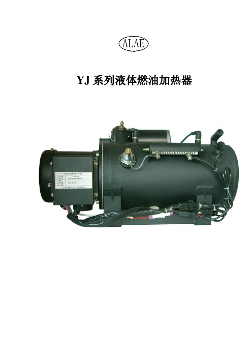
YJ系列液体燃油加热器目录一、系统介绍二、技术参数三、产品结构及工作原理四、配套安装及使用注意事项五、使用方法六、故障分析及排除措施七、维护与保养附图:管路连接图一. 系统介绍:YJ系列燃油液体加热器是与发动机相独立的采暖设备,是通过燃烧换热原理,加热循环系统内冷却介质的加热器产品。
与一般水暖暖风机不同,在发动机不开动的情况下,也可以供车厢内取暖。
它为全自动控制,其控制部分具有低温启动、高温停止、重复点火、故障报警停机等功能,整机采用不锈钢焊接,耐腐蚀性强,使用寿命长,并具有热效率高、升温快、污染小、乘坐舒适、无异味、噪音低、不干燥、节油等优点。
加热器在具有给车厢采暖功能的同时,还具有给水冷发动机作低温预热的功能,它能自动地将冷却液温度恒定在65℃~ 85℃之间。
冬季使用本机预热发动机,可显著降低发动机磨损、油耗和大气污染,延长发动机寿命。
二. 技术参数:1.热流量:11.6kw耗油量:1.23kg/h水泵流量:30L/min温度控制:防冻液温度65~85℃电瓶压降:约0.04V/h(使用180Ah、24V蓄电池)。
水泵功率120W,主电机功率30W可以直接从油箱取油,也可以配专用油箱(本机自带油泵吸油)2.外形尺寸:540×300×300mm安装尺寸:装配孔 M12螺纹孔装配尺寸:250×130mm安装在车身主车架上,可以在挂在车架两侧(油箱后侧),或者车架中间(万向十字接头上方)。
操纵面板尺寸:86×58×60mm1 2 3 4 5 6 7 8 9图310 1112 13 14 15 16 17 18 19图41.电器控制盒2.橡胶塞3.点火塞4.放气阀5.进水温度传感器6.降压电阻7.出水温度传感器8.出水口9.火焰温度传感器10.水泵及电机11.进水口12.放水塞13.主支架14.水泵支架15.电磁阀进油管16.电磁阀17.电磁阀回油管18. 电磁阀出油管19.端盖原理:电动机带动油泵、助燃风扇及雾化器转动。
燃油加热器产品资料

YJ系列液体燃油加热器目录一、系统介绍二、技术参数三、产品结构及工作原理四、配套安装及使用注意事项五、使用方法六、故障分析及排除措施七、维护与保养附图:管路连接图一. 系统介绍:YJ系列燃油液体加热器是与发动机相独立的采暖设备,是通过燃烧换热原理,加热循环系统内冷却介质的加热器产品。
与一般水暖暖风机不同,在发动机不开动的情况下,也可以供车厢内取暖。
它为全自动控制,其控制部分具有低温启动、高温停止、重复点火、故障报警停机等功能,整机采用不锈钢焊接,耐腐蚀性强,使用寿命长,并具有热效率高、升温快、污染小、乘坐舒适、无异味、噪音低、不干燥、节油等优点。
加热器在具有给车厢采暖功能的同时,还具有给水冷发动机作低温预热的功能,它能自动地将冷却液温度恒定在65℃~ 85℃之间。
冬季使用本机预热发动机,可显著降低发动机磨损、油耗和大气污染,延长发动机寿命。
二. 技术参数:1.热流量:11.6kw耗油量:1.23kg/h水泵流量:30L/min温度控制:防冻液温度65~85℃电瓶压降:约0.04V/h(使用180Ah、24V蓄电池)。
水泵功率120W,主电机功率30W可以直接从油箱取油,也可以配专用油箱(本机自带油泵吸油)2.外形尺寸:540×300×300mm安装尺寸:装配孔 M12螺纹孔装配尺寸:250×130mm安装在车身主车架上,可以在挂在车架两侧(油箱后侧),或者车架中间(万向十字接头上方)。
操纵面板尺寸:86×58×60mm1 2 3 4 5 6 7 8 9图310 1112 14 15 16 17 18 19图41.电器控制盒2.橡胶塞3.点火塞4.放气阀5.进水温度传感器6.降压电阻7.出水温度传感器8.出水口9.火焰温度传感器10.水泵及电机11.进水口12.放水塞13.主支架14.水泵支架15.电磁阀进油管16.电磁阀17.电磁阀回油管18. 电磁阀出油管19.端盖原理:电动机带动油泵、助燃风扇及雾化器转动。
空气预热器安装指导书

空气预热器安装指导书施工方案会签表1.工程概况 (1)2.基本建设依据 (2)3.空气预热器安装部分技术参数 (3)4.施工前准备工作 (3)5.作业进度及劳动力安排 (6)6.安装程序及步骤 (6)7.质量保证措施 (14)8.安全措施 (15)9.环境保护措施 (20)10.试运注意事项 (24)11.交底记录: (25)供热机组扩建工程,加装两台哈尔滨锅炉厂生产的hg-1165/17.5smr3型亚临界自然循环炉,搭载两台全模式三分仓容克式空气预热器。
该预热器是利用锅炉烟气中吸收热量来加热空气的一种热交换器,其作用是回收烟气余热,提高锅炉效率。
其主要有烟风道连接板,冷端连接板,热端连接板,冷端连接环,热端弓形环,主座架,侧座架(元件盒修护板),转子外壳板组件,导向轴承,支承轴承,转子,转子模式扇形仓,转子中心筒,导向端轴,支承端轴,传动装置,膨胀装置;其附属装置包括:吹灰器,水冲洗装置,观察装置;该预热器型号30.5-vi(t)-2333-smr,转子名义直径11818mm,三分式,转子旋转依次经过烟气侧、一次风侧、二次风侧,一次风开口70°逆转,传热元件总高:2804mm。
预热器布置在bh-bk排、b32.2-b19.1轴及b16.7-b3.6轴之间,预热器通过膨胀装置组件支撑在.10950mm钢结构支承梁上,膨胀装置组件焊接于钢架。
其上部钢结构在21000mm处有两根横梁(2hc52)穿过,此钢梁在安装钢结构时应预留。
安装过程中与省煤器及尾部过热器存在交叉作业。
此设备由哈尔滨锅炉厂有限责任公司提供技术支持。
2.1hg—1165/17.5—hm3型锅炉总图,预热器加装图、预热器加装说明书。
2.2《电力建设施工及验收技术规范》(锅炉机组篇,管道篇,dl/t5047—95,1996年版)。
2.3《火电施工质量检验及评定标准》(锅炉篇,1996年版)2.4东电一公司企业标准《质量、环境、职业身心健康安全管理文件》(q/nepc(2)001-024202)2.5《电力建设安全工作规程》(dl5009.1-2002)2.6采用施工机械性能表中:300t履带性能表中300t履带吊选用主臂60m,副臂36m工况。
燃油加热器简明维修手册

汽车燃油加热器 简明使用维修手册河北宏业永盛汽车加热器股份有限公司2011年7月使用燃油加热器前请仔细阅读本手册,本手册适用于YJ型、YJP型加热器的使用与维修。
一、YJ型加热器及零部件二、YJP型加热器及零部件三、燃油加热器使用注意事项四、YJ型燃油加热器常见故障与排除五、YJP型燃油加热器常见故障与排除六、日常检查与保养维护七、主要零部件的拆卸如在安装、使用、维修过程中如有疑问请拨打售后服务电话:0317-*******-8262234一、YJ 加热器与主要零部件过热传感器冷却泵二、YJP型加热器及零部件:电磁阀点火电极燃油泵预热管三、燃油加热器使用注意事项:1、加热器油路系统中应使用与环境温度相适应牌号的柴油;加热器循环系统内应使用与环境温度相适应牌号的防冻液。
(1)天气转冷时,油箱要及时更换对应标号的柴油或煤油,否则会引起加热器故障。
更换柴油后,打开加热器,使其工作至少3分钟,使油路全部充满更换后的柴油。
柴油标号参见下表:环境温度 柴油标号5℃ — -5℃ -10#-5℃ — -15℃ -20#-15℃— -30℃ -35#-35℃及其以下 -50#(2)天气转冷时,请确认更换对应标号的防冻液,否则会导致加热器损坏。
加注防冻液时,必须先打开加热器放气阀及管路放气阀,待放气阀尤其是加热器放气阀处无气体冒出时,关闭放气阀,打开加热器水泵开关,打开汽车发动机,继续加注,直至循环系统内充满冷却液介质为止。
防冻液标号参见下表:环境温度 防冻液标号5℃—— -25℃ -30#-25℃以下 -35# (或更低标号)2、冲洗车辆时,禁止用水枪对安装加热器位置冲洗,否则会引起加热器故障。
3、严禁利用车辆总电源开关关闭加热器,以防止主机内部过热,要先关闭加热器开关,3-5分钟后,待加热器开关绿色指示灯熄灭后,方可关闭车辆总电源,严禁加热器开关指示灯亮着断掉加热器电源。
四、YJ型燃油加热器常见故障与排除故障现象 原因分析 排除措施加热器开机后无法点火、排烟口滴油电热塞损坏 检查更换电热塞加热器开机后点不着火,指示灯闪一长五短1、油管堵或主油箱内缺油2、油管接头密封不良,漏气3、电磁阀打不开4、助燃风口堵塞5、点火传感器故障1、疏通油路,油箱加油2、紧固接头卡子3、检查故障,更换电磁阀4、清理助燃风口5、更换或调整点火传感器加热器在高原等地区着火,但工作过程中持续冒黑烟 进风量不足调整进风口(增大进风)加热器到温度不停机 1、水温传感器故障 1、用万用表检测水2、传感器位置不能正确感应实际循环系统的温度 温传感器两端,停机时电压超出 1.93±0.1伏,即为传感器故障。
TGH34PL-2燃气加热器使用说明书
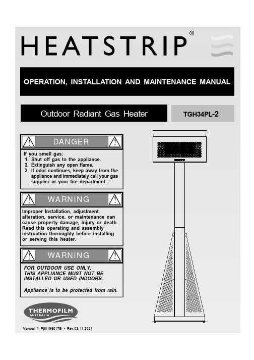
Manual # P8*******B - Rev.03.11.2021DANGER!!1.2.3.If you smell gas:Shut off gas to the appliance.Extinguish any open flame.If odor continues, keep away from the appliance and immediately call your gas supplier or your fire department .WARNING!!Improper Installation, adjustment,alteration, service, or maintenance can cause property damage, injury or death.Read this operating and assemblyinstruction thoroughly before installing or serving this heater.WARNING!!FOR OUTDOOR USE ONLY.THIS APPLIANCE MUST NOT BE INSTALLED OR USED INDOORS.Appliance is to be protected from rain.OPERATION, INSTALLATION AND MAINTENANCEMANUALOutdoor Radiant Gas HeaterTGH34PL -21. This appliance must be used only for outdoor area and shall not be used in a building, garage or any other enclosed area. This appliance must not be installed or used indoors. This appliance must be placed on level firm ground. This appliance shall only be used in an above ground open-air situation with natural ventilation, without stagnant areas, where gas leakage and products of combustion are rapidly dispersed by wind and natural convection.2. Any guard or other protective device removed for servicing (conducted by an authorized person) must be replaced before operating the heater.3. Do not install in very windy locations. Do not transport or move the heater while it is operating.4. Children and adults should be alerted to the hazards of high surface temperatures and should stay away to avoid burns or clothing ignition.5. Children should be carefully supervised when they are in the area of the heater.6. Clothing or other flammable materials should not be hung from the heater or placed on or near the heater.7. Do not perform maintenance until heater has been turned off, and heater has cooled to room temperature.8. Do not expose the burner to water or moisture. The appliance must be protected from rain.9. Do not use the heater if any parts are damaged by exposure to water until the appliance is inspected or repaired by an authorized service person.10. The installer is to ensure that the requirements of the local authority, local gas fitting regulations,municipal building codes, and any other relevant statutory regulations are carried out.11. Certain materials or items, when stored under or near the appliance, will be subjected to radiant heat and could be seriously damaged.12. All leak tests should be done with a soap solution. Never use an open flame to check for leaks.!!13. Do not use the heater until all visible gasconnections have been leak tested.Never test for leakswith an open flame. Prior to first use, at the beginning of each season, or every time your LP Gas Cylinder is changed, you must check for gas leaks.14. The radiant heater is NOT intended to be installed on recreational vehicles or boats.15. Do not attempt to alter the unit in any manner.16. Do not paint any surface of the heater or reflector.17. Burner and circulation air passageways of the heater must be kept clean. Frequent cleaning may be required as necessary.18. Check the heater immediately if any of the following occurs:- The heater does not reach temperature.- The burner makes popping noise during use (a slight noise is normal when the burner is ignited or extinguished).19. This appliance is not intended for use by young or infirm person unless they have been adequately supervised by a responsible person to ensure that they can use the appliance safely.20. Check for damage to the appliance regularly. If damage to the appliance is suspected, discontinue use immediately and contact the supplier or qualified person for repair.21. Avoid inhaling fumes emitted from the heater's first use. Smoke and odour from the burning of oils used in manufacturing will appear. Both the smoke and odour will dissipate after approximately 30minutes.22. Storage of an appliance indoors is permissible only if the cylinder is disconnected and removed from the appliance.23. Do not store a spare LP gas cylinder under or near this appliance.24. The heater head angle retaining pin must be inserted if transporting the heater to ensure no damage occurs during transit.!!Do not store or use flammable liquids or vapors inthe vicinity of this appliance.An LPG cylinder not connected for use shall not be stored in the vicinity of this appliance.1.2.!!ŸŸ!READ THIS MANUAL CAREFULLY before installing or operating this product.Failure to comply with these instructions could result in a fire or explosion that could cause serious bodily injury, death or property damage.!DO NOT PLACE ARTICLES ON OR AGAINST THIS APPLIANCE.DO NOT USE OR STORE FLAMMABLE MATERIALS NEAR THIS APPLIANCE.DO NOT SPRAY AEROSOLS OR FLAMMABLE MATERIALS IN THE VICINITY OF THIS APPLIANCE WHILE IS IN OPERATION.!!This appliance is for outdoor use only.This appliance must be placed on level firm ground.This appliance shall only be used in an above ground open-air situation with natural ventilation, without stagnant areas, where gas leakage and products of combustion are rapidly dispersed by wind and natural convection.Any enclosure in which the appliance is used shall comply with one of the following:1. An enclosure with walls on all sides, but at least one permanent opening at ground level.2. Within a partial enclosure that includes an overhead cover and no more than two walls.3. Within a partial enclosure that includes an overhead cover and more that two walls, the following shall apply:- At least 25% of the total wall area is completely open.- At least 30% of the remaining wall area is open and unrestricted.- In the case of balconies, at least 20% of the total wall area shall be and remain open and unrestricted.The following diagrams are examples of outdoor areas.These same principles apply to any other shaped area.LPG CYLINDER USE AND SAFETYHOSE AND REGULATOR SAFETYClose LPG cylinder valve whenever the heateris not in use.This heater is for outdoor use only. The LPG gas cylinder must be disconnected when the heater is not in use for prolonged periods. If the heater is to be stored indoors, you must remove and store the LPG gas cylinderoutdoors. Store in a well ventilated area and out of reach of children,The heater is designed for use with a 9KG LPG cylinder. Do not connect the heater to LPG cylinder exceeding this capacity.The gas cylinder should be filled by a reputable gas dealer, or exchanged at a reputable cylinder exchange outlet.Always keep cylinder in an upright position.Always close the cylinder valve when the heater is not in use.Do not subject the gas cylinder to excessive heat.ŸŸŸŸŸŸThe regulator and hose assembly supplied with the heater are suitable for liquefied petroleum gas.A gas regulator adjusted to have and outlet pressure of 2.75 kpa is supplied for LCC27connection to the LPG cylinder. The regulator and hose assembly supplied with the heater must be used. Replacement regulators and hose assemblies must be those specified by the appliance manufacturer.When connecting the hose and regulator assembly to the gas cylinder, take care to avoid unnecessary twisting of the flexible hose.After the assembly has been secured, turn on the gas and check for leaks by brushing a soap and water solution over all connections.The presence of bubbles will indicate a gas escape. DO NO TEST FOR GAS ESCAPES WITH AN OPEN FLAME.If you are unable to correct the leak bytightening the connections, turn off the gas and contact your place of purchase immediately.Always ensure the patio heater is kept away from flammable materials and the gas cylinder clear of any heat source.When changing over from an empty gascylinder to a full one, make sure this proce-dure is carried out in a flame-free atmosphere.Inspect the gas hose before each use and when replacing the gas cylinder. If the hose is cracked, cut, abraded or damaged in any way,the heater must not be operated. The hose must be replaced if damaged or when statutory conditions require it. Contact your place of purchase if uncertain.The hose and regulator should be disconnected from the cylinder when the heater is not in use. DO NOT DISCONNECT THE GAS HOSE FROM THE APPLIANCE.The hose assembly must be replaced prior to the appliance being put into operation if there is evidence of excessive abrasion or wear, or if the hose is damaged. The replacement hose must be purchased from Thermofilm Australia Pty Ltd.ŸŸŸŸŸŸŸŸŸNEVER OPERATE THIS HEATER WITHOUT A REGULATOR.DO NOT BYPASS THE SAFETY DEVICES.DO NOT ATTEMPT TO CONVERT THE HEATER FOR NATURAL GAS USE.FAILURE TO COMPLY WITH THESEINSTRUCTIONS COULD RESULT IN A FIRE OR EXPLOSION WHICH COULD CAUSE SERIOUS BODILY INJURY, DEATH ,OR PROPERTY DAMAGE.!!ŸŸŸŸThis appliance must only be used in a well ventilated area. The following clearance should be followed:The heater should not be installed:- Where heat ignition can cause damage to gas cylinders/lines- Near other combustible materials.- In open locations subject to rain.Heater should be installed to allow adequate:- Clearance around air openings to combustion chamber.- Clearance from combustible material- Provisions for accessibility and clearance for combustion and ventilating air supply.Installation ClearancesDimension and Clearance DetailIMPORTANT 1 : MINIMUM CLEARANCES TO COMBUSTIBLE MATERIAL, FROM TOP 500mm, SIDE 1000mm, FRONT 1000mm, REAR 300mm.IMPORTANT 2 : ALWAYS LOCATE AND OPERATE HEATER ON A FLAT-LEVEL SURFACE.Hardware Diagram for TGH34PL-2Pan Head Screw M6x10mm Qty. 29Part # S112M06102Pan Head Screw M5x10mm Qty. 7Part #S112M05102Pin Φ6 x 150mm Qty. 1Part # P0*******D Bolt M6 x 150mm Qty. 1Part #S020100223R Cotter Pin Qty. 1Part # P0*******BWing Nut M6Qty. 1Part # S411M0606AAA BatteryParts ListCAUTION : To assemble this heater, you should obtain assistance from another person when handling the larger, heavierpieces.Install the Lower PostInstall Side PanelsInstall Head Deflector and BatteryPlace two Side Panels onto the Base.Install the Left Side Panel to the Lower Post usingto the Base using 3 Pan Head Screws M6x10mm.tighten all the screws securely.Install Head Deflector to the Head Assembly using 3 Pan Head Screws M5x10mm, then tighten all the screws securely.Pan Head Screw M6x10mm Qty. 5Part # S112M06102Pan Head Screw M6x10mm Qty. 10Part # S112M06102Pan Head Screw M5x10mm Qty. 3Part # S112M05102attach 2 Pan Head Screw on Base halfway.231then tighten all the screws securely.Attach AA BatteryAA Battery4Install Heater HeadLay Heater Upper Assembly on a non-abrasive surface (carton or table).Remove pre-assembly screw from back panel of post upper.Insert the Regulator with Hose to the Upper Post and attach Back PanelInstall the Upper Rear Panel to the Lower Post using 2 Pan Head Screws M6x10mm.Install the Upper Rear Panel to the Side Panels using 4 Pan Head Screws M5x10mm, then tighten all the screws securely.Place the Lower Real Panel in position over the gas bottle enclosure area.Install Rear PanelsPan Head Screw M6x10mm Qty. 2Part # S112M06102Pan Head Screw M5x10mm Qty. 4Part # S112M051026Install Post ConnectorInsert the Upper Post with heater head and attach 6 Pan Head Screws M6x10mm, then tighten all the screws securely.5Pan Head Screw M6x10mm Qty. 6Part # S112M06102Never test for leaks with an open flame. Prior to first use, at the beginning of each season, or every time your LP Gas Cylinder is changed, you must check for gas leaks. Follow these three steps:Check for Gas Leaks!Failure to read and follow the Use and Care Instructions could result in a fire or explosion that could cause serious bodily injury, death or property damage.!Make a soap solution bymixing one part liquid detergent and four parts water.1. 1 part liquid detergent4 parts water 2.Pull "off" down, then turn on gas at3.Apply the soap solution to all visible gas connections. If bubbles appear in the soap solution the connections are not properly sealed. Check each fitting and tighten or repair as necessary.WARNING!!If you have a gas leak that cannot be repaired by tightening, turn off the gas at the source,disconnect fuel line from your heater and call (03) 9562 3455 or your gas supplier for repair assistance.Before each use, check all hoses for cracks, nicks, cuts,burns or abrasions. If a hose is damaged in any way,do not use your heater before replacing the hose with an authorized part from the Parts List. Also make sure all gas supply connections are securely tightened.Familiarize yourself with the safety and Use and Care Instructions in this Manual. Do not smoke while lighting heater or checking gas supply connections.Always light the heater standing to the side of the heater, never light the heater standing in front.(3) Once the pilot flame is established, keep pulling the trigger down for 10 seconds to ensure that the burner remains lit.(4) If the burner does not ignite, turn gas off at source and Pull the trigger "OFF" down. Wait at least 5 minutes for gas to clear, then retry. If your heater still fails to light,turn the Control Knob and gas source OFF. Wait 5 min-utes for gas to clear and then conduct a gas leak test. If no leaks are detected, repeat the lighting procedure.5. When the heater is not in use, Pull the trigger "OFF"down and turn off the gas source.Failure to replace a faulty hose, secure gas supply connections before proceeding to the LightingProcedures could result in a fire or explosion that could cause serious bodily injury, death, or property damage.!!Heater Lighting Instructions(1)LP Gas CylinderWARNING!!Failure to comply with these instructions could result in a fire or explosion that could cause serious bodily injury, death or property damage.Keep heater area clear and free from combustible materials, gasoline and other flammable vapors and liquids.Keep the ventilation openings of the cylinder enclosure cabinet free and clear of debris.CLEANING AND MAINTENANCEBefore initial use, and periodically thereafter, we suggest you wash your heater using a mild soap and warm water solution.You can use a wash cloth or sponge for this process.Never use abrasive cleaners, scrubbers or stiff wire brushes of any type on your heater. These will scratch painted surfaces during the cleaning process.Ensure the appliance is dried after cleaning to prevent rusting.It is recommended the heater be operated on high heat after cleaning to ensure the appliance is dry.Proper care and maintenance will keep your heater in top operating condition and prolong its life. Follow these cleaning procedures on a timely basis and your heater will stay clean and operate with minimum effort.CAUTION: Be sure your heater is OFF and cool before cleaning.CLEANING EXTERIOR PAINTED SURFACES。
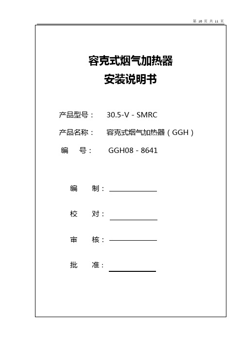
容克式烟气加热器安装说明书
10、 安装、焊接静密封,必要时进行修割。
11、 重新安装为安装模块而未装妥的壳板、刚性环等。打开外壳大检修 门,完成转子、外壳等的焊接工作。
12、 安装上下水管组件及吹灰器等(可根据鳞片树脂施工的实际情况,调整水管的安装时间。)。
13、 安装所有径向、轴向密封片(未安装好转子壳板的模块除外)。在涂层前进行扇形板、轴向密封板的调整。
14、涂层前安装旁路密封片。
15、焊妥各撑管,焊接外壳、管路上的保温抓钉。
16、按密封间隙表调整好密封片和密封板的间隙,复查合格后,作好纪录。焊接固定好扇形板、轴向密封板,安装静密封、净化风槽口等组件。焊接时保证扇形板和轴向密封板的焊接变形量最小。
9、 用临时拉撑将中心筒和端轴装配件固定在下梁(非扇形板)上,调整并保持其垂直。
10、 起吊上梁,移去上梁上的临时支撑,使上梁中间孔穿过导向端轴。使上梁垂直就位于主支座上(注意对中)。按图进行焊接。
11、 根据导向轴承组件图安装导向轴承组件。并请按导向轴承组件图纸的要求预紧轴承。
12、 拆去端轴上的所有临时拉撑。
9、根据总包方的调试计划,对各个设备进行逐项调试。
5、启动前检查项目
6.1、加热器的位置是否正确?
6.2、胀缩节和烟风道的安装情况如何?是否有加热器以外的负荷作用在加热器上?
6.3、下部梁下(中心支撑和两端)的滑动板是否装妥?定位工字钢是否焊妥?支承脚是否能自由膨胀?
6.4、扇形板和密封盘是否装妥?扇形板是否固定?
17、根据涂层敷装图及防腐厂家的有关技术要求进行外壳内部防腐施工。必要时,应当对局部区域进行二次防腐施工。