FS_11C14开发板用户手册 V4.0
Si1140 开发板用户指南说明书
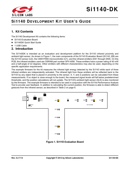
Rev. 0.3 7/13Copyright © 2013 by Silicon LaboratoriesSi1140-DKEVELOPMENT IT SER S UIDE1. Kit ContentsThe Si1140 Development Kit contains the following items:⏹Si1143 Evaluation Board ⏹Si1140DK Quick Start Guide ⏹ 1 USB Cable2. IntroductionThe Si1140DK is intended as an evaluation and development platform for the Si1143 infrared proximity and ambient light sensor. As shown in Figure 1, the main components of the Si1143 Evaluation Board (Si1143_EB) are the Si1143 sensor (U2), the C8051F800 microcontroller (U1), and the infrared emitters (DS1 through DS9). On this PCB, the infrared emitters used are OSRAM part number SFH 4056. These emitters have a power rating of 40mW and a half-angle of 22 degrees. Other emitters with different characteristics may also be used, depending on the specific application requirements.The example firmware for the kit measures the infrared light energy detected by the Si1143 while each of three infrared emitters are independently activated. The infrared light from these emitters will be reflected back to the Si1143 by any object that is placed in proximity to the sensor. X, Y , and Z positions can be calculated from these measurements. If no object is close enough to the board, the measured signal levels will fall below predetermined thresholds, and the position calculations will not update. The Si1143’s ambient light sensor (ALS) is also monitored by the firmware. The example firmware is intended to be used in conjunction with the Si114x Performance Analysis Tool to provide user feedback. In addition to calculating the current position, the firmware is able to detect different gestures from the infrared sensor, as described in Table 2 on page 6.Figure 1.Si1143 Evaluation BoardDS13DS10DS11DS12+5V_INSi1140-DK3. Software OverviewThere are several optional software packages available to support the Si1143 Evaluation Board. The Si114x Performance Analysis Tool can be used for initial evaluation to collect data from the board over the USB interface and display it graphically. For users ready to develop their own software, the Si114x Programmer’s Toolkit API enables rapid development of Si114x software in a PC environment using the Si1143 Evaluation Board. The Si114x Programmer’s Toolkit contains example source code that allows developers to get started quickly and then tailor the code to their needs. In addition, the Silicon Labs Integrated Development Environment (IDE) provides a means of developing code for the C8051F800 and uses the USB connection on the board to program the MCU and perform in-system debugging. All of the supporting software can be downloaded from the web at the URL /products/sensors/pages/optical-sensor-software.aspx.3.1. Using the Si1143 Evaluation Board with the Performance Analysis ToolThe Si1143 Evaluation Board is supported by the Si114x Performance Analysis Tool. The Performance Analysis Tool allows users to see real-time infrared proximity and ambient light measurements from the Si1143 in a graphical form. The communications interface to the Si1143 Evaluation Board is provided over the USB connection.To use the Performance Analysis Tool with the Si1143 Evaluation Board:1.Connect the Si1143 Evaluation Board to the PC using a USB unch the Performance Analysis Tool from the Start menu.3.Select the board from the “Devices” menu (it should show up as “TS” followed by a serial number).4.Select the channels you wish to display on the picture of the slider board that appears. The individual channels available are described in “3.1.1. Channel Selection” .5.Click the green “Acquisition” arrow to begin collecting data.Note:The Performance Analysis Tool, Si114x Programmer’s Toolkit, and the IDE cannot connect to the Si1143 EvaluationBoard at the same time. Be certain to disconnect from the board in one software package before trying to connect in the other.Figure 2 shows an example of the Performance Analysis Tool output when connected to the Si1143 Evaluation Board. To generate the graph, a hand was moved above the slider board. The selected traces shown are the raw data measurements for the amount of Infrared light being reflected onto the part. The pink trace represents the distance from infrared emitter DS1; the green trace represents the distance from infrared emitter DS9, and the yellow trace represents the distance from infrared emitter DS5.Figure 2.Performance Analysis Tool Main WindowSi1140-DK3.1.1. Channel SelectionSelecting which channels to display is done by checking the appropriate boxes on the Board Representation window, shown in Figure 3, and the Generic Data window, shown in Figure 4. There are two different groups of measurements available from the example firmware: raw data channels and generic data channels.3.1.1.1. Raw Data ChannelsThe raw data measurements can be seen by selecting the channels from the Board Representation window, shown in Figure 3. The two types of raw data measurements are ambient light and infrared proximity.1.Raw ambient light measurements. The ambient light channels are Channel 0 (red) and Channel 1(blue).Channel 0 displays measurements of the ambient visible light while Channel 1 displays measurements of the ambient infrared light.2.Raw infrared proximity measurements. The infrared proximity channels are Channel 2 (pink) readings using DS1, Channel 3 (green) readings using DS9, and Channel 4 (yellow) readings using DS5. The output isproportional to the amount of infrared light being reflected onto the part by an object above the board. These outputs are 16-bit unsigned values.Figure3.Raw Data Channel SelectionSi1140-DK3.1.1.2. Generic Data ChannelsThe generic data channels contain any data generated by the host MCU. These 16-bit channels can be anything from simple debug channels to calculated position values. See Table1 for an explanation of all the channels shown in Figure4.Figure4.Generic Data Channel SelectionSi1140-DKTable 1. Generic Data ChannelsName Label TypeDescriptionG0Rad1Linearized Distance Measurements Using characterization of the PS measurements with objects at certain distances, it is possible to estimate thedistance of an object based on the PS measurementvalue. These three channels represent the distance esti-mations for each LED's measurement.G1Rad2G2Rad3G3X(mm)Estimated Location CoordinatesWith the approximate distance measurements above, an X, Y , and Z estimation can be made. These estimations are given in units of mm.G4Y(mm)G5Z(mm)G6iLED1LED Drive Current LevelsEach LED driver has a specific LED drive current setting for it. These values are given in units of mA.G7iLED2G8iLED3G9VISAutoRanging Ambient OutputsAutoRanging will automatically change the modes of the photodiodes to avoid saturation. When changing modes, the raw data output changes levels, but AutoRanging will scale the raw data so that all measurements are on the same scale. The output from this channel is the pro-cessed value which can be used without knowledge of the photodiode modes.G10IRG11PS1AutoRanging PS OutputsThese channels are the AutoRanging PS output from the device. Raw data measurements are processed by the AutoRanging firmware to make all the readingsacross different modes have the same magnitude. Since the device switches modes to compensate for ambient light, the raw data will show jumps when changing modes. These outputs will not display the jumps because the firmware is stitching the raw outputs together.G12PS2G13PS3G14VIS s State of Ambient Visible System These channels help indicate what mode the sensor is in during each of their respective measurements. The four possible modes are as follows: Low Light, High Sensitiv-ity, High Signal, and Sunlight. These modes are num-bered from zero to three. For more information about each mode, please consult the data sheet.G15IR st State of Ambient IR System G16PS st State of PS SystemG17PS1bl PS Baseline LevelsAutoRanging uses baselining to determine the no-detect threshold for readings. Any readings below the values shown on these channels will be considered no-detect readings. Any values higher than this baseline will be shown in the AutoRanging PS Outputs above.G18PS2bl G19PS3bl G20N/A UnusedThe unused channels are not in use by software, but they are available in firmware to use as needed.G21N/ASi1140-DK3.1.2. Gesture SensingIn addition to infrared and ambient light measurements and distance calculations, the example firmware contains algorithms for gesture recognition. When connected to the board with the Performance Analysis Tool, a group window will appear, as shown in Figure 5. When a gesture is recognized by firmware, the gesture name and parameter information will be added to the top of the 3D Gesture group. Four gestures are supported by the example code. The parameters for each gesture are listed in Table 2.Figure 5.Performance Analysis Tool Group WindowTable 2. Recognized GesturesGesture Name Parameter Parameter Range Description of ActionSwipe Left Speed 118 (Slow to Fast)Move hand rapidly from the right side to the left side of the board.Swipe Right Speed 118 (Slow to Fast)Move hand rapidly from the left side to the right side of the board.Swipe Up Speed 118 (Slow to Fast)Move hand rapidly from the bottom to the top of the board.Swipe DownSpeed118 (Slow to Fast)Move hand rapidly from the top to the bottom of the board.Si1140-DK3.2. Si114x Programmer’s Toolkit3.2.1. Software APIThe Si114x Programmer’s Toolkit API enables rapid development of Si114x software in a PC environment using the Si1140DK. By emulating an I2C interface over USB, the Si114x Programmer’s Toolkit API allows source code to be developed on a PC and then migrated quickly and easily to an MCU environment once target hardware is available. Either commercially-available or free PC-based C compilers can be used for software development with the Si114x Programmer’s Toolkit API.The Si114x Programmer’s Toolkit API also includes the Si114x Waveform Viewer Application. This tool runs in conjunction with user applications to display and debug the measurements taken from the Si1140DK.Note:The Performance Analysis Tool, Si114x Programmer’s Toolkit and IDE cannot connect to the Si1143 Evaluation Board at the same time. Be certain to disconnect from the board in one software package before trying to connect in the other. 3.2.2. Command Line UtilitiesFor evaluation of the Si1140DK without the need to develop and compile source code, a flexible set of command line utilities is also provided with the Si114x Programmer’s Toolkit. These utilities can be used to configure and read samples from the Si1140DK. For automated configuration and scripting, the command line utilities can be embedded into .bat files.3.2.3. Sample Source CodeFor faster application development, the Si114x Programmer’s Toolkit contains example source code for the Si1140DK and for each of the command line utilities. Developers can get started quickly by using the Si114x example source code and then tailoring it to their needs.3.2.4. Downloading the Si114x Programmer’s ToolkitThe Si114x Programmer’s Toolkit and associated documentation is available from the web at the URL/products/sensors/pages/optical-sensor-software.aspx.Si1140-DK3.3. Silicon Laboratories IDEThe Silicon Laboratories IDE integrates a source-code editor, a source-level debugger, and an in-system Flash programmer. This tool can be used to develop and debug code for the C8051F800 MCU which is included on the Si1143 Evaluation Board. The use of several third-party compilers and assemblers is supported by the IDE.3.3.1. IDE System RequirementsThe Silicon Laboratories IDE requirements:⏹Pentium-class host PC running Microsoft Windows 2000 or newer.⏹One available USB port.3.3.2. Third Party ToolsetsThe Silicon Laboratories IDE has native support for many 8051 compilers. The full list of natively supported tools is as follows:⏹Keil⏹IAR⏹Raisonance⏹Tasking⏹SDCC3.3.3. Downloading the Example Firmware ImageSource code that has been developed and compiled for the C8051F800 MCU on the Si1143 Evaluation Board may be downloaded to the board using the Silicon Laboratories IDE. Follow the instructions below to update or refresh the .HEX image in the Si1143 Evaluation Board.1.Connect the Si1143 Evaluation Board to the PC using a USB cable.unch the Silicon Labs IDE, and click on Options->Connection Options.3.Select “USB Debug Adapter”, and then select the board from the list (it should show up as “TS” followed by aserial number).4.Select “C2” as the debug interface, and press “OK”.5.Connect to the board by pressing the “Connect” icon or by using the keyboard shortcut, Alt+C.6.Click on the “Download” icon, or use the keyboard shortcut Alt+D.7.In the download dialog window, click “Browse”.8.Change to Files of Type “Intel Hex (*.hex)” and then browse to select the file.9.Click “Open” then “Download”.10.To run the new image, either press “Run” or “Disconnect” in the IDE.Note:The Performance Analysis Tool, Si114x Programmer’s Toolkit and IDE cannot connect to the Si1143 Evaluation Board at the same time. Be certain to disconnect from the board in one software package before trying to connect in the other.Si1140-DK 4. SchematicSi1140-DKD OCUMENT C HANGE L IST Revision 0.2 to Revision 0.3Replaced QuickSense Studio references and instructions with Si114x Programmer’s Toolkit. Silicon Laboratories Inc.400 West Cesar ChavezAustin, TX 78701USASmart.Connected.Energy-Friendly .Products/products Quality /quality Support and Community DisclaimerSilicon Laboratories intends to provide customers with the latest, accurate, and in-depth documentation of all peripherals and modules available for system and software implementers using or intending to use the Silicon Laboratories products. Characterization data, available modules and peripherals, memory sizes and memory addresses refer to each specific device, and "Typical" parameters provided can and do vary in different applications. Application examples described herein are for illustrative purposes only. Silicon Laboratories reserves the right to make changes without further notice and limitation to product information, specifications, and descriptions herein, and does not give warranties as to the accuracy or completeness of the included information. Silicon Laboratories shall have no liability for the consequences of use of the information supplied herein. This document does not imply or express copyright licenses granted hereunder to design or fabricate any integrated circuits. The products are not designed or authorized to be used within any Life Support System without the specific written consent of Silicon Laboratories. A "Life Support System" is any product or system intended to support or sustain life and/or health, which, if it fails, can be reasonably expected to result in significant personal injury or death. Silicon Laboratories products are not designed or authorized for military applications. Silicon Laboratories products shall under no circumstances be used in weapons of mass destruction including (but not limited to) nuclear, biological or chemical weapons, or missiles capable of delivering such weapons.Trademark InformationSilicon Laboratories Inc.® , Silicon Laboratories®, Silicon Labs®, SiLabs® and the Silicon Labs logo®, Bluegiga®, Bluegiga Logo®, Clockbuilder®, CMEMS®, DSPLL®, EFM®, EFM32®, EFR, Ember®, Energy Micro, Energy Micro logo and combinations thereof, "the world’s most energy friendly microcontrollers", Ember®, EZLink®, EZRadio®, EZRadioPRO®, Gecko®, ISOmodem®, Precision32®, ProSLIC®, Simplicity Studio®, SiPHY®, Telegesis, the Telegesis Logo®, USBXpress® and others are trademarks or registered trademarks of Silicon Laborato-ries Inc. ARM, CORTEX, Cortex-M3 and THUMB are trademarks or registered trademarks of ARM Holdings. Keil is a registered trademark of ARM Limited. All other products or brand names mentioned herein are trademarks of their respective holders.。
英飞拓V2011矩阵中文说明书
请在安装前仔细阅读安装使用手册,并妥善保存以备将来查阅。
安全建议与警告
所有电子设备应避免受潮,远离火源或强磁场。 擦拭设备表面时,请使用干燥、柔软的抹布。 请保持设备周围良好的通风环境。 设备长时间不用时,请断开电源。 请使用厂家建议的原配件。 电源及电线应安装在远离地面和入口处的地方。 设备的维护需由专业人员进行。 建议妥善保管包装箱,方便设备的转移或搬运。
另外,系统提供有简洁完备的编程菜单可方便用户快速地进行整个系统参数的设置及编程。
注意
版权声明
本手册内容(包括文字与图片)的版权为 Infinova 公司所有。任何个人或法人实体,未经 Infinova 公司的书面授权许可, 不得以任Infinova 公司保留在事先不进行任何通知的情况下,对本手册的内容以及产品技术规格进行修改的权利,以便向用户提供 最新、最先进的产品。用户可从 Infinova 公司的网站 上获得最近的产品更新资料。
第二章 系统安装及连接 ............................................................ 4 2.1 安装................................................................................... 4 2.2 产品外观........................................................................... 4 2.2.1 前面板视图 ............................................................... 4 2.2.2 后面板视图 ............................................................... 4 2.3 硬件连接........................................................................... 4 2.3.1 视频输入连接 ........................................................... 4 2.3.2 控制码连接 ............................................................... 4 2.3.3 视频输出连接 ........................................................... 5 2.3.4 报警输入连接 ........................................................... 6 2.3.5 通讯口连接 ............................................................... 6 2.3.6 继电器输出连接 ....................................................... 7 2.3.7 以太网连接 ............................................................... 7 2.3.8 编程监视器连接 ....................................................... 8 2.3.9 电源连接 ................................................................... 8 2.3.10 网络视频连接 ......................................................... 8
AVP50G 开发板用户手册说明书

Logos FPGA开发平台用户手册AVP50G开发板2 / 51芯驿电子科技(上海)有限公司文档版本控制目录文档版本控制 (2)一、开发板简介 (6)二、FPGA核心板 (11)(一)简介 (11)(二)FPGA (12)(三)有源晶振 (13)(四)DDR3 (15)(五)QSPI Flash (17)(六)LED灯 (18)(七)扩展接口 (20)(八)电源 (24)(九)结构图 (27)三、扩展板 (28)(一)简介 (28)(二)VGA显示接口 (29)(三)HDMI输出接口 (30)(四)HDMI输入接口 (33)(五)视频输入接口 (35)(六)千兆以太网接口 (37)(七)ARM控制器 (39)1)实时时钟 (40)2)EEPROM (41)3)LED (42)4)USB串口 (43)5)SD卡 (44)(八)摄像头接口 (45)(九)扩展口 (46)(十)JTAG接口 (48)(十一)按键 (49)3 / 514 / 51芯驿电子科技(上海)有限公司(十二) 供电电源 (50)5 / 51专业级紫光同创 FPGA 视频图像处理开发平台(型号:AVP50G )正式发布了,为了让您对此开发平台可以快速了解,我们编写了此用户手册。
这款FPGA 视频图像处理开发平台具备HDMI 输入,DVI 输出,千兆以太网,CMOS Camera 接口和Micro SD 卡座等外设。
这极大的丰富了视频图像处理板的功能,不仅满足FPGA 视频图像处理的功能,还为视频图像存储,视频图像的网络通信提供了可能。
因此,这款开发平台可以堪称“专业级”和"全能级“。
这样的一款产品非常适合即将从事或者正在从事FPGA 视频图像处理或者视频图像通信及存储的学生、工程师等群体。
6 / 51芯驿电子科技(上海)有限公司一、 开发板简介在这里,对这款紫光同创 FPGA 开发平台进行简单的功能介绍。
开发板的整个结构,继承了我们一贯的核心板+扩展板的模式来设计的。
深圳颢天成 LPC11CxxDemo-V1 开发板说明书
LPC11CxxDemo-V1开发板用户手册V1.0深圳颢天成科技有限公司1 概述1.1简介LPC11CxxDemo-V1深圳市颢天成科技有限公司推出的一款基于NXP公司LPC11Cxx 系列处理器(Cortex-M0内核)的全功能评估板。
该板功能接口丰富,是一个应用开发好平台,也是学习者的首选。
配合JLINK、ULINK调试工具一起使用,更方便开发调试,所有的例程都是MDK下的完整工程,从而为自己的应用开发节省了时间,提高了效率。
1.2 硬件资源列表●LPC11Cxx(32位RISC性能处理器)32位ARM Cortex-M0结构优化●4个LED发光管,1个电源发光管●1个mini型USB插座,支持全速USB 2.0●1个RESET按键,1个ISP按键,1个WAKEUP按键,1个普通按键●1个UART支持RS-232●SSP接口●I2C接口●8通道10位ADC模块●1个JTAG/SWD调试接口●供电方式:USB供电1.3 软件资源列表例程名称 测试功能描述Blinky LED灯闪烁GPIO GPIO口边沿中断触发SSP SSP同步串行通讯SysTiick 通过系统滴答延时实现LED灯闪烁Timer32 通过32位定时器延时实现LED灯闪烁UART UART串口发送接收字符WDT 看门狗定时器应用实例I2C I2C主模式测试1.4 产品清单核对:LPC11CxxDemo-V1开发板1块128*64的LCD屏1块交叉串口线1条USB A-B线1根LPC11Cxx Demo-V1光盘一张1.5 使用入门1.5.1 电源LPC11CxxDemo-V1评估板采用USB供电方式,通过主板上的USB Device端口供电,供电正常时,评估板上的电源指示灯亮。
1.5.2 连接PC端推荐使用KEIL集成开发环境,通过JTAG连接仿真器到评估板,即可进行应用程序的调试和开发。
1.5.3 硬件原理:参加原理图1.5.4 镜像文件:编译好的可直接下载运行HEX文件1.6 出厂设置和硬件测试1)跳线J5 OFF不连接,不使用ISP下载2)串口1在一些例程中作为实验板与PC机的交互接口。
LPC1114教程原创

设置成数字 IO 就可以使用了。让然在使用别的复用功能时也一样首先需要设置
IO 配置寄存器将管脚设置在你需要的复用功能上。
下面就该了解一下通用 GPIO 的寄存器了,在通用的 GPIO 寄存器中分两部分,
一部分是数字功能,一部分是中断功能(这一节暂且不讨论),数字功能主要由
2 个寄存器构成,一个是方向寄存器 DIR 一个是数据寄存器 DATA,方向寄存器
九、LED 指示灯 在我们的开发板上有 3 个普通 LED 灯,是通过 IO 口直接控制的,采用的是灌电 流的方式驱动的。电路原理图如图所示:
பைடு நூலகம்
十、按键电路 开发板上有 3 个普通按键,通过这 3 个普通的按键可以做按键实验,熟悉按键的 读取方式。连接管脚如图所示:
十一、SD 卡接口 本开发板支持大容量的 SD 卡读写,这样我的再多的数据都可以通过 SD 卡保存 了,一些图片等信息也可以通过存储在SD卡中保存。SD卡通过 SPI 总线操作。 接口原理图如下:
口,这样你就可以在你的电脑上看见一个虚拟的移动存储器了,把里面的固件删 除,复制上你的新固件(程序),整个下载过程就完成了,怎么样简单吧!如果 还不明白那就看看 ZLG 或者 NXP 关于 USB 下载的文档哈! 六、一直都有的 24c02 24c02 是一种 IIC 协议的 EEPROM 存储芯片,芯片本身很便宜,在开发板上的低 位却不低,几乎所有的开发板都有它的踪迹,这是由于 2 个原因,一是通过一个 IIC 总线的器件可以学习 IIC 协议和内置 IIC 控制器的学习,二是在 MCU 运行的 过程中有很多数据是需要 EEPROM 保存的。基于这两个原因这个小芯片一直存 在于各个开发板就不奇怪了。下面是 24c02 部分的原理图。
开发板用户手册
开发板用户手册摘要:1.开发板简介2.开发板硬件配置3.软件开发环境搭建4.编程实例与实践5.常见问题与解决方案6.技术支持与资源正文:【开发板简介】开发板是一种集成了处理器、存储器、输入输出接口等多种功能于一体的计算机硬件平台,用于进行软硬件开发和测试。
本手册所介绍的开发板,具有强大的性能、丰富的外设接口以及易于使用的开发环境,是进行嵌入式系统开发、物联网应用、人工智能等领域开发的理想选择。
【开发板硬件配置】本开发板硬件配置如下:1.处理器:采用高性能的ARM 处理器,主频可达XXX MHz。
2.存储器:配备XXX MB 的DDR 内存和XXX MB 的Flash 存储,支持最大XXX MB 的MicroSD 卡扩展。
3.显示接口:支持XXX 分辨率的LCD 显示屏。
4.通信接口:具备以太网、蓝牙、Wi-Fi、LoRa 等多种通信方式。
5.输入输出接口:提供按键、LED 指示灯、串口、I2C、SPI、GPIO 等多种外设接口。
6.电源接口:支持DCXXXV 输入电压。
【软件开发环境搭建】为了方便开发者进行软件开发,我们提供了以下工具和资源:1.开发板固件:提供稳定可靠的Linux 操作系统和Android 操作系统固件。
2.编程工具:支持Keil、IAR 等主流的嵌入式开发环境。
3.调试工具:提供在线调试工具,支持断点调试、单步执行等功能。
4.开发库:提供丰富的开发库,包括网络通信、图形界面、文件系统等。
5.技术文档:提供详细的开发板用户手册、硬件参考手册、接口协议等文档。
【编程实例与实践】本手册提供了以下编程实例,供开发者学习和参考:1.LED 闪烁实验2.按键输入实验3.串口通信实验4.网络通信实验5.图形界面设计实验【常见问题与解决方案】在开发过程中,可能会遇到一些常见问题,如下所示:1.问题:无法启动开发板解决方案:检查电源线是否接触良好,检查开发板上的电源指示灯是否亮起。
2.问题:无法连接串口解决方案:检查串口线是否接触良好,尝试使用其他串口工具重新连接。
单片机说明书
•
San Jose, CA 95134-1709 • 408-943-2600 Revised September 27, 2005
CY7C68013A/CY7C68014A CY7C68015A/CY7C68016A
1.1 Features (CY7C68013A/14A only)
USB 2.0 SIE or external transceiver implementations. With EZ-USB FX2LP, the Cypress Smart SIE handles most of the USB 1.1 and 2.0 protocol in hardware, freeing the embedded microcontroller for application-specific functions and decreasing development time to ensure USB compatibility. The General Programmable Interface (GPIF) and Master/Slave Endpoint FIFO (8- or 16-bit data bus) provides an easy and glueless interface to popular interfaces such as ATA, UTOPIA, EPP, PCMCIA, and most DSP/processors. The FX2LP draws considerably less current than the FX2 (CY7C68013), has double the on-chip code/data RAM and is fit, form and function compatible with the 56-, 100-, and 128pin FX2. Five packages are defined for the family: 56VFBGA, 56 SSOP, 56 QFN, 100 TQFP, and 128 TQFP.
02_Speaker蜂鸣器

//使能
break;
case 0:
……..
break;
}
}
init_timer32PWM 函数:
void init_timer32PWM(uint8_t timer_num, uint32_t period, uint8_t match_enable) {
disable_timer32(timer_num); if (timer_num == 1) {
能、 使能匹配通道 3 设置 PWM 周期*/
/* Setup the match registers */ /* set the period value to a global variable */ timer32_1_period = period; LPC_TMR32B1->MR3 = timer32_1_period; LPC_TMR32B1->MR0 = timer32_1_period/2;
实验 02_Speaker 的使用
【实验目的】: 1、掌握 PWM 功能 2、利用 PWM 定时器实现蜂鸣器控制
【实验环境】: 1、FS_11C14 开发板 2、FS_Colink V2.0 3、RealView MDK(Keil uVision4)
【实验步骤】: 1、 在 Speaker 文件夹下找到并打开 project.uvproj 文件; 2、 编译此工程; 3、 通过 FS_Colink 下载编译好的工程到 FS_11C14 开发板; 4、 按 Reset 键复位开发板; 5、 学习 PL-2303HX 芯片 6、 查看 LPC11C14 芯片手册,对照程序分析 PWM 的实现过程; 7、 改变 PWM 占空比,听声音的变化。
/* Setup the external match register */
- 1、下载文档前请自行甄别文档内容的完整性,平台不提供额外的编辑、内容补充、找答案等附加服务。
- 2、"仅部分预览"的文档,不可在线预览部分如存在完整性等问题,可反馈申请退款(可完整预览的文档不适用该条件!)。
- 3、如文档侵犯您的权益,请联系客服反馈,我们会尽快为您处理(人工客服工作时间:9:00-18:30)。
产品标准配置
1 2 3 4 5 FS_11C14开发板1块 Colink 仿真器1个 RFID 卡一个 USB 线2根 DVD 光盘1张
产品选配模块
1 2 1 ZigBee 模块 实验箱包装
FS_11C14 开发板用户手册
选配 ZigBee 模块 FS_ZICM2410简介
ZigBee 采用的是 CEL 公司 ZICM2410模块。 FS_ZICM2410带有 usb 转串口芯片, 可以方便的连接 PC 机或其它带有 USB 主机接口的设备,从而实现和 FS_11C14组 网通讯。 FS_ZICM2410模块还可以利用 ZICM2410的扩展资源实现对电位器、按键中 断、LED 灯等外设的编程控制。
第二章 硬件资源
2.1 硬件资源概览
锂电池供电 CoLink 仿 真 器 CAN总 线 带速度反馈的风扇 R S 4 8 5 /4 2 2
U s b 转U a r t RFID 光敏传感
ZigBee
蜂鸣器
三轴加速度传感
温湿度传感
Oled显 示
图 2.1 开发板实体
2.2 处理器
基于 ARM Cortex-M0 内核的 LPC11C14,低功耗、低成本、丰富的外设资 源。 此处理器主要有如下特点: - 带有 SWD 调试功能(4 个断点)的 50MHz Cortex-M0 控制器 - 32 个可嵌套向量中断、4 个优先级、最多 13 个拥有专用中断的 GPIO - 带片上 CANopen 驱动器的 CAN 2.0B 的 CAN 控制器 - UART、2 个 SPI、 I2C - 具备脉宽调制/匹配/捕捉功能的 2 个 16 位和 2 个 32 位计时器,1 个 24 位 系统计时器 - 具备±1LSB DNL 的 8 通道高精度 10 位 ADC - 42 根 5V 兼容 GPIO 引脚,选择引脚高电平驱动(20mA) - 32kB 片上内部 Flash、8kB 片上内部 RAM
FS_11C14 开发板用户手册
FS_11C14 开发板用户手册 V4.0 物 联 网 开 发 平 台
北京华清远见研发中心
2012 年 6 月
FS_11C14 开发板用户手册
目 录
第一章 开发板概述...................................................................................................... 1 1.1 简介................................................................................................................. 1 1.2 主要配置......................................................................................................... 2 第二章 硬件资源.......................................................................................................... 3 2.1 硬件资源概览................................................................................................. 3 2.2 处理器............................................................................................................. 3 2.3 板载主要传感器............................................................................................. 4 2.4 RFID 设备模块................................................................................................ 4 2.5 ZigBee 无线通信模块.................................................................................... 5 2.6 仿真器.............................................................................................................. 5 第三章 板载实验代码.................................................................................................. 6 3.1 配套案例、实验说明...................................................................................... 6 3.2 配套案例.......................................................................................................... 6 3.3 配套实验.......................................................................................................... 6 第四章 RealView MDK 开发环境使用......................................................................... 8 4.1 RealView MDK 开发环境简介....................................................................... 8 4.2 创建工程......................................................................................................... 8 4.2.1 创建工程文件...................................................................................... 8 4.2.2 选择设备.............................................................................................. 9 4.3 编译和连接................................................................................................... 10 4.3.1 设置目标硬件的工具选项................................................................ 10 4.3.2 编译链接工程.................................................................................... 11 第五章 CoLink 仿真器安装及调试........................................................................... 12 5.1 CoLink 环境安装安装.................................................................................. 12 第一步 CoLink 固件升级............................................................................. 12 第二步 CoLink USB 驱动程序安装............................................................. 12 第三步 CoLink 与 RealView MDK 连接的插件安装................................... 13 备注................................................................................................................ 13 5.2 Colink 程序调试.......................................................................................... 13 5.2.1 仿真器的配置.................................................................................... 14 5.2.2 程序下载的配置................................................................................ 14 5.2.3 程序调试运行.................................................................................... 16