快恢复保险丝规格书
自恢复保险丝选型手册

产品图片Figure 1 Figure 2 Figure 3 Figure 4 GR16V系列产品型号及电气参数I H : 保持电流:在25℃环境温度、静止空气下的最大工作电流。
I T : 动作电流:在25℃环境温度、静止空气下启动保护的最小流。
VMax : 元件所能承受的最大工作电压。
I Max : 元件在额定电压下所能承受的最大故障电流。
R0 : 标称电阻:在25℃环境温度、静止空气下的额定零功率电阻。
GR16V系列动作时间曲线图GR30V系列产品型号及电气参数I H : 保持电流:在25℃环境温度、静止空气下的最大工作电流。
I T : 动作电流:在25℃环境温度、静止空气下启动保护的最小电流。
V Max : 元件所能承受的最大工作电压。
I Max : 元件在额定电压下所能承受的最大故障电流。
R0 : 标称电阻:在25℃环境温度、静止空气下的额定零功率电阻。
GR30V系列动作时间曲线图GR72V系列产品型号及电气参数I H : 保持电流:在25℃环境温度、静止空气下的最大工作电流。
I T : 动作电流:在25℃环境温度、静止空气下启动保护的最小电流。
V Max : 元件所能承受的最大工作电压。
I Max : 元件在额定电压下所能承受的最大故障电流。
R0 : 标称电阻:在25℃环境温度、静止空气下的额定零功率电阻。
GR72V系列动作时间曲线图GR135系列产品型号及电气参数I H :保持电流:在25℃环境温度、静止空气下的最大工作电流。
I T :动作电流:在25℃环境温度、静止空气下启动保护的最小电流。
V Max :元件所能承受的最大工作电压。
I Max :元件在额定电压下所能承受的最大故障电流。
R0 :标称电阻:在25℃环境温度、静止空气下的额定零功率电阻。
GR135V系列动作时间曲线图GR265V系列产品型号及电气参数I H : 保持电流:在25℃环境温度、静止空气下的最大工作电流。
I T : 动作电流:在25℃环境温度、静止空气下启动保护的最小电流。
JSR250系列自恢复保险丝数据手册
4、 依据步骤 2 选出的自恢复保险丝及步骤 3 所计算的 Ih 值,在其后规格表中选出符合的自恢复保险丝元 件,选出的自恢复保险丝元件的之 Ih 值必须大于或等于步骤 3 所计算的 Ih 值
5、 依据选出的元件,对照规格中提供的数据,确认该种规格自恢复保险丝元件的动作时间小于被保护电路
需要的时间。
7.6 4.6 3.1 0.6 2
JSR250090 250 3 90 0.180 10.0 31.0 31 5.0 5.0
2.5
1
JSR250090U 250 3 90 0.180 10.0 31.0 31 6.0 9.3 5.1
7.6 4.6 3.1 0.6 2
JSR250100 250 3 100 0.200 9.0 16..0 27 5.0 5.0
Maximum Contour Size(mm)
图
(V) (A) (mA) (A) (Ω) (Ω) (Ω) A(max) B(max) C(typ) D(min) E(max) F(typ) R(max) 号
JSR250040U 250 3 40 0.080 30 75.0 90 6.0 9.3 5.1
7.6 6.0
3.1 0.8 3
JSR250600U 250 10 600 1.200 0.60 1.70 4 13.0 17.0 5.1
7.6 6.0
3.1 0.8 3
JSR250800U 250 10 800 1.600 0.40 1.00 3 20.0 22.0 5.1
7.6 6.0
3.1 0.8 2
选用方法
1、 确定被保护电路中的平均工作电流值 I 及工作电压 V,(Peak 值不用考虑)
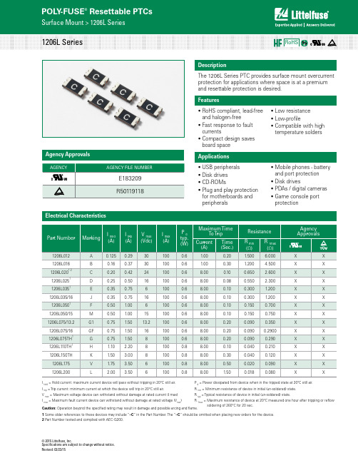
Littelfuse力特1206自恢复保险丝规格书
© 2015 Littelfuse, Inc.Specifications are subject to change without notice. Revised: 02/23/15The 1206L Series PTC provides surface mount overcurrent protection for applications where space is at a premium and resettable protection is desired.Electrical CharacteristicsI hold = Hold current: maximum current device will pass without tripping in 20°C still air. I trip = Trip current: minimum current at which the device will trip in 20°C still air.V max = Maximum voltage device can withstand without damage at rated current (I max) I max = Maximum fault current device can withstand without damage at rated voltage (V max )P d = Power dissipated from device when in the tripped state at 20°C still air.R min = Minimum resistance of device in initial (un-soldered) state.R typ = Typical resistance of device in initial (un-soldered) state.R 1max =M aximum resistance of device at 20°C measured one hour after tripping or reflow soldering of 260°C for 20 sec.DescriptionAgency ApprovalsFeaturesApplications• R oHS compliant, lead-free and halogen-free • F ast response to fault currents • C ompact design saves board space• L ow resistance • L ow-profile • C ompatible with high temperature solders• U SB peripherals • D isk drives • C D-ROMs • P lug and play protection for motherboards and peripherals• M obile phones - battery and port protection • D isk drives • P DAs / digital cameras • G ame console port protectionCaution: Operation beyond the specified rating may result in damage and possible arcing and flame.1 Some older references to these devices may include “–C “ in the Part Number. The “–C “ should be omitted when placing new orders for the device.2 Part Number tested and complied with AEC-Q200.© 2015 Littelfuse, Inc. Specifications are subject to change without notice.Revised: 02/23/15T emperature Rerating Curve-40-30-20-100102030405060708010%30%50%70%90%110%130%150%170%Temperature (°C)PercentageofRatedCurrentAverage Time Current CurvesThe average time current curves and Temperature Rerating curve performance is affectedby a number or variables, and these curves provided as guidance only. Customer mustverify the performance in their application..12A.16A.2A.25A.35A.35A/15V.5A.5A/15V.75A1.A1.1A1.5A2.A100001210L OLD.5A.1A.2A.35A.5A.75A1.1A1.5A1.75A2.A0.010.11101000.1110TimeinSecondsCurrent in Amperes1210L.5A.1A.2A.35A.5A.75A.75A/241.1A1.5A1.75A2.A0.010.11101000.1110TimeinSecondsCurrent in Amperes1206L.12A.16A.2A.25A.35A,.35A/15V.5A,.5A/15V.75A.75A/13.2V1.1A1.5A1.75A2.ANotes: The temperature rerating data is only for reference, please contact Littelfuse technical support for detail temperature rerating information.© 2015 Littelfuse, Inc.Specifications are subject to change without notice. Revised: 02/23/15Environmental SpecificationsPhysical Specifications-- All temperature refer to topside of the package, measured on the package body surface -- If reflow temperature exceeds the recommended profile, devices may not meet the performance requirements-- Recommended reflow methods: IR, vapor phase oven, hot air oven, N 2 environment for lead-- Recommended maximum paste thickness is 0.25mm (0.010 i nch)-- Devices can be cleaned using standard industry methods and solvents -- Devices can be reworked using the standard industry practices© 2015 Littelfuse, Inc.Specifications are subject to change without notice.Revised: 02/23/15(.040)MARKING CODE VARIES WITH AMPERAGE RATING(SEE ELECTRICAL CHARACTERISTICS CHART)SHOWN IS 1.0 AMP RATINGWARNING• Users shall independently assess the suitability of these devices for each of their applications• Operation of these devices beyond the stated maximum ratings could result in damage to the devices and lead to electrical arcing and/or fire• These devices are intended to protect against the effects of temporary over-current or over-temperature conditions and are not intended to perform as protective devices where such conditions are expected to be repetitive or prolonged in duration• Exposure to silicon-based oils, solvents, electrolytes, acids, and similar materials can adversely affect the performance of these PPTC devices• These devices undergo thermal expansion under fault conditions, and thus shall be provided with adequate space and be protected against mechanical stresses • Circuits with inductance may generate a voltage (L di/dt) above the rated voltage of the PPTC device.© 2015 Littelfuse, Inc.Specifications are subject to change without notice. Revised: 02/23/15=10,000 Y =4,000 W =3,000 P =2,000Tape & Reel-A: Automotive grade Blank: Standard version© 2015 Littelfuse, Inc.Specifications are subject to change without notice.Revised: 02/23/15。
自恢复保险丝选型手册

产品图片Figure 1 Figure 2 Figure 3 Figure 4 GR16V系列产品型号及电气参数产品型号I H(A)I T(A)V Max(V)I Max(A)R0(mΩ)A MaxB MaxCD Max线径(mm)图形宽度高度间距厚度GR16-0500.50 1.01640160-4806.611.35.1±0.53.00.5F1GR16-0650.65 1.31640120-3606.612.05.1±0.53.00.5F1GR16-0750.75 1.51640110-2307.012.05.1±0.53.00.5F1GR16-0900.9 1.8164070-1807.012.05.1±0.53.00.5F3GR16-110 1.10 2.2164060-1406.614.55.1±0.53.00.5F3GR16-120 1.20 2.4164050-1408.813.85.1±0.53.00.5F1GR16-135 1.35 2.7164040-1108.813.85.1±0.53.00.5F3GR16-160 1.60 3.2164035-1108.815.55.1±0.53.00.5F3GR16-185 1.85 3.7164030-9010.016.05.1±0.53.00.5F3GR16-250 2.5 5.0164020-6011.318.55.1±0.53.00.5F3GR16-300 3.0 5.11610030-97.58.811.85.1±0.53.00.8F4I H : 保持电流:在25℃环境温度、静止空气下旳最大工作电流。
I T : 动作电流:在25℃环境温度、静止空气下启动保护旳最小流。
VMax : 元件所能承受旳最大工作电压。
I Max : 元件在额定电压下所能承受旳最大故障电流。
自恢复保险丝SMD0603封装参数型号规格书大全

The SMD0603 Series PTC providessurface mount over-currentprotection for applications where space is at a premium and resettable protection is desired.u RoHS compliant, Lead-Free and Halogen-Free u Fast time-to-tripu Compact design saves board space u Low resistance uLow-profileu Mobile phones - battery and port protection u Game console port protection u USB peripherals u Disk driveu PDAS / digital cameras u Power ports uGeneral electronicsHold Current Trip Current Rated Voltage Max Current Typical Power Maximum TimeTo Trip Resistance Part NumberI hold (A)I trip (A) V max (Vdc) I max (A) P dtyp. (W) Current (A) Time (Sec.) R min (Ω) R 1max (Ω) SMD0603-010 0.10 0.30 15 40 0.5 0.50 1.00 0.90 6.00 SMD0603-020 0.20 0.50 9.0 40 0.5 1.00 0.60 0.55 3.50 SMD0603-025 0.25 0.55 9.0 40 0.5 8.00 0.80 0.50 3.00 SMD0603-035 0.35 0.75 6.0 40 0.5 8.00 0.10 0.20 1.40 SMD0603-050 0.50 1.00 6.0 40 0.5 8.00 0.10 0.10 0.80 SMD0603-075 0.75 1.50 6.0 40 0.5 8.00 0.10 0.06 0.45 SMD0603-100 1.00 2.00 6.0 40 0.5 8.00 0.10 0.04 0.30I hold = Hold current: maximum current device will pass without tripping in 23°C still air. I trip = Trip current: minimum current at which the device will trip in 23°C still air. V max = Maximum voltage device can withstand without damage at rated current (I max ) I max = Maximum fault current device can withstand without damage at rated voltage (V max ) P dtyp.= Power dissipated from device when in the tripped state at 23°C still air. R min = Minimum resistance of device in initial (un-soldered) state.R 1max = Maximum resistance of device at 23°C measured one hour after tripping.Caution: Operation beyond the speci fied rating may result in damage and possible arcing and flame.Profile FeaturePb-Free Assembly Average Ramp-Up Rate (T S max to T P ) 3°C/second max. Preheat :Temperature Min (T S min) Temperature Max (T S max) Time (T S min to T S max)150°C 200°C60-180 seconds Time maintained above: Temperature(TL) Time (tL)217°C60-150 seconds Peak/Classification Temperature(T P ): 260°C Time within 5°C of actual peak: Temperature20-40 seconds Ramp-down Rate:6°C/ second max. Time 25°C to Peak Temperature8 minutes max.Note: All temperatures refer to of the package, measured on the package body surface.Solder reflowDue to “Lead Free ” nature, Temperature and Dwelling time for the soldering zone is higher than those for Regular. This may cause damage to other components.1. Recommended max past thickness > 0.25mm.2. Devices can be cleaned using standard methods and aqueous solvent.3. Rework use standard industry practices.4. Storage Environment : < 30/ 60%RH ℃Caution:1. If reflow temperatures exceed the recommended profile, devices may not meet the performance requirements.2. Devices are not designed to be wave soldered to the bottom side of the board.Terminal pad material Pure TinSoldering CharacteristicsMeets EIA specification RS 186-9E, ANSI/J-std-002 Category 3hold Ambient Temperature (°C)A B C DeviceNominalNominal Nominal 0603 Series1.000.701.00Model-40℃-20℃0℃25℃40℃50℃60℃70℃85℃SMD0603-010 0.13 0.12 0.11 0.10 0.08 0.07 0.06 0.05 0.03 SMD0603-020 0.27 0.25 0.23 0.20 0.17 0.14 0.12 0.10 0.07 SMD0603-025 0.32 0.29 0.27 0.25 0.21 0.18 0.16 0.05 0.03 SMD0603-035 0.47 0.41 0.38 0.35 0.29 0.26 0.24 0.20 0.14 SMD0603-050 0.67 0.59 0.54 0.50 0.41 0.37 0.34 0.29 0.20 SMD0603-075 0.98 0.85 0.81 0.75 0.60 0.54 0.44 0.40 0.31 SMD0603-1001.301.121.081.00 0.800.720.580.530.42Maximum ambient operating temperature(Tmao) vs. hold current (I hold)flame.u PPTC device are intended for occasional over-current protection. Application for repeated over-current condition and/or prolonged trip are not anticipated.uAvoid contact of PPTC device with chemical solvent. Prolonged contact will damage the device performance.0.33 (8.4)0.512(13.0)Arbor Hole DiameterDimensions are in inches (and millimeters)0.157 (4.0) 0.059 (1.5)Diameter Cover tape(4.0)(5.4)。
陆海自恢复保险丝规格书

陆海自恢复保险丝规格书1.产品概述陆海自恢复保险丝是一种电气故障保护装置,可用于电力系统、电子设备和汽车电气系统等领域。
它具有自动恢复的功能,即在保护电路过载或短路时,保险丝会自动恢复正常工作状态,确保设备或系统的安全运行。
2.产品特点2.1自动恢复功能:当电路过载或短路发生时,保险丝会自动断开电路,起到保护作用。
一旦过载或短路情况解除,保险丝会自动恢复通电状态,避免频繁更换保险丝的繁琐操作。
2.2快速响应:保险丝具有快速断电和断电恢复的特性,能够在电路故障发生时迅速切断电流,避免设备受损。
2.3高可靠性:产品采用高品质材料和先进生产工艺,具有良好的电气性能和耐高温、耐冲击的特点,能够长时间稳定运行。
2.4简单安装:保险丝尺寸小巧、重量轻,易于安装和更换,适用于各种电路环境。
3.技术指标3.1额定电压(Rated Voltage):产品可选额定电压范围广,通常为12V、24V、48V等常见电压级别。
3.2额定电流(Rated Current):产品可根据实际需求选择不同的额定电流,常见的额定电流有1A、2A、5A等多种规格。
3.3断开时间(Trip Time):保险丝的断开时间需要符合相关标准,一般在故障发生后的数毫秒内切断电路。
3.4自恢复时间(Recovery Time):在故障消除后,保险丝需要在较短的时间内自动恢复通电状态,一般在几十秒到几分钟之间。
4.使用方法与注意事项4.1安装:将保险丝正确安装到电路中,确保保险丝的两端与电路连接牢固、接触良好。
4.2更换:当保险丝断开时,应根据电气规范和设备要求及时更换保险丝,以保证电路运行安全。
4.3额定参数匹配:在选择和使用保险丝时,应根据实际电路的额定电压和额定电流需求,选择适合的保险丝规格。
4.4温度限制:保险丝在使用过程中应避免超过其额定温度范围,以免影响产品性能和寿命。
5.应用领域陆海自恢复保险丝广泛应用于电力系统、电子设备和汽车电气系统等领域,主要用于过载和短路保护。
陆海自恢复保险丝规格书
陆海自恢复保险丝规格书近年来,随着科技的不断发展,人们对电子设备的依赖程度越来越高。
然而,电子设备在使用过程中往往会遇到各种故障,其中一个常见的问题就是保险丝的烧断。
为了解决这个问题,陆海公司研发了一种自恢复保险丝,并制定了相应的规格书。
一、产品概述自恢复保险丝是一种能够在过载或短路情况下自动切断电流,并在故障解除后自动恢复通电的电子元件。
它采用了特殊的材料和结构设计,能够在故障发生时迅速切断电流,避免设备受损。
一旦故障解除,保险丝会自动恢复通电,不需要人工更换。
二、产品特点1. 自恢复功能:当电流超过额定值或发生短路时,保险丝会自动切断电流,避免设备受损。
一旦故障解除,保险丝会自动恢复通电,无需人工干预。
2. 高可靠性:采用优质材料和精密制造工艺,保证产品的稳定性和可靠性,减少故障率。
3. 快速响应:自恢复保险丝具有快速切断电流的特点,能够在故障发生时迅速切断电路,保护设备安全。
4. 多种规格可选:根据不同设备的需求,陆海公司提供了多种规格的自恢复保险丝,以满足不同场景的使用需求。
三、产品规格1. 额定电流:根据客户需求,陆海公司提供了从0.5A到10A不同额定电流的自恢复保险丝。
2. 额定电压:自恢复保险丝的额定电压为250V。
3. 触发电流:自恢复保险丝的触发电流为额定电流的1.5倍,确保在过载情况下能够及时切断电流。
4. 外观尺寸:自恢复保险丝的外观尺寸为5mm x 20mm,适用于大多数电子设备。
四、应用领域自恢复保险丝广泛应用于各种电子设备中,包括电视机、电脑、手机、音响等。
它能够有效保护设备免受过载和短路的损害,延长设备的使用寿命。
五、使用注意事项1. 在安装和更换自恢复保险丝时,务必断开电源,以免发生触电事故。
2. 自恢复保险丝只能用于额定电流和电压范围内的设备,不得超过其额定值使用。
3. 如发现自恢复保险丝烧断,请检查设备是否存在其他故障,及时解决问题后再更换保险丝。
总结:陆海自恢复保险丝是一种能够在过载或短路情况下自动切断电流,并在故障解除后自动恢复通电的电子元件。
自恢复保险丝PPTC规格书中的参数
自恢复保险丝PPTC规格书中的参数
每种产品都有自己的规格书,自恢复保险丝当然也是有的,那幺保险丝的规格书怎幺看呢?这个是很简单的,只要你知道规格书中的参数所代表的含义,就可以清楚快速的查看自恢复保险丝PTC规格书了。
1、IH(保持电流):在25℃静止空气环境下,高分子热敏电阻PTC保持不动作情况下可以通过的最大电流。
在限定环境条件下,装置可保持无限长的时间,而不会从低阻状态转变至高阻状态。
(通过PTC的电流不足以使PTC自热温升超过居里温度,这样的电流称为不动作电流,不动作电流的最大值称为最大不动作电流)
2、IT(动作电流):在25℃静止空气环境下,高分子热敏电阻PTC在限定的时间内动作的最小稳态电流。
3、Vmax 最大电压(耐压值):在限定条件下,高分子热敏电阻PTC动作时,能安全承受的最高电压。
即热敏电阻的耐压值。
超过此值,热敏电阻有可能被击穿,不能恢复。
此值通常被列在规格书中的耐压值一栏里。
自恢复保险丝JK60封装参数型号规格书大全
UN60SeriesUN60series radial leaded PTCs are designed to provide over-current protection for low voltage (≤72V)applications where space is not a concern and resettable protection is preferred.◆Cured,flame retardant epoxy polymer meets UL 94V-0requirements◆72V operating voltage ◆Fast time-to-trip◆RoHS compliant,Lead-Free and Halogen-Free◆USB hubs ,ports and peripherals ◆Power ports ◆IEEE1394ports◆Motor protection◆Automotive application ◆Computers and peripherals ◆General electronicsPartNumber I hold (A)I trip (A)V max (Vdc)I max (A)P dtyp.(W)Maximum TimeTo Trip Resistance Current (A)Time (Sec.)R min (Ω)R max (Ω)R 1max (Ω)UN60-0050.050.1072400.220.15157.3020.0030.00UN60-0100.100.2072400.380.3012 2.507.5012.00UN60-0170.170.3472400.480.5110 2.00 5.208.00UN60-0200.200.4072400.410.6010 1.50 3.00 4.40UN60-0250.250.5072400.450.7510 1.10 2.20 3.00UN60-0300.300.6072400.490.90100.80 1.60 2.10UN60-0400.400.8072400.56 1.20100.50 1.00 1.29UN60-0500.50 1.0072400.77 1.50120.450.90 1.17UN60-0650.65 1.3072400.88 1.95120.300.600.72UN60-0750.75 1.5072400.92 2.25120.250.500.60UN60-0900.90 1.8072400.99 2.70120.200.400.47UN60-110 1.10 2.207240 1.50 3.30150.150.320.38UN60-135 1.35 2.707240 1.70 4.05150.120.240.30UN60-160 1.60 3.207240 1.90 4.80200.090.180.22UN60-185 1.85 3.707240 2.10 5.55200.080.160.20UN60-200 2.00 4.007240 2.10 6.00200.080.160.20UN60-250 2.50 5.007240 2.507.50250.050.110.13UN60-300 3.00 6.007240 2.809.00250.040.080.10UN60-375 3.757.507240 3.2011.25250.030.0650.08UN60-500 5.0010.007240 3.2015250.0250.050.06I hold =Hold current:maximum current device will pass without tripping in 25°C still air.I trip =Trip current:minimum current at which the device will trip in 25°C still air.V max =Maximum voltage device can withstand without damage at rated current (I max )I max =Maximum fault current device can withstand without damage at rated voltage (V max )P dtyp.=Power dissipated from device when in the tripped state at 25°C still air.R min =Minimum resistance of device in initial (un-soldered)state.R max =Maximum resistance of device in initial (un-soldered)state.R 1max =Maximum resistance of device at 25°C measured one hour after tripping.Caution:Operation beyond the specified rating may result in damage and possible arcing and flame.DescriptionFeaturesElectrical ParametersApplicableUN60SeriesPart NumberAmbient Operation Temperature-40°C-20°C0°C25°C40°C 50°C60°C70°C85°CHold Current (A)UN60-0050.0780.0680.060.050.040.0360.0320.0270.02UN60-0100.160.140.120.100.080.0720.0630.0540.04UN60-0170.260.230.200.170.140.120.110.090.07UN60-0200.310.270.240.200.160.140.130.110.08UN60-0250.390.340.300.250.200.180.160.140.10UN60-0300.470.410.360.300.240.220.200.160.12UN60-0400.620.540.480.400.320.290.250.220.16UN60-0500.780.680.600.500.410.360.320.270.20UN60-065 1.010.880.770.650.530.470.410.350.26UN60-075 1.16 1.020.890.750.610.540.470.410.30UN60-090 1.40 1.22 1.070.900.730.650.570.490.36UN60-110 1.71 1.50 1.31 1.100.890.790.690.590.44UN60-135 2.09 1.84 1.61 1.35 1.090.970.850.730.54UN60-160 2.48 2.18 1.90 1.60 1.30 1.15 1.010.860.64UN60-185 2.87 2.52 2.20 1.85 1.50 1.33 1.17 1.000.74UN60-200 3.10 2.72 2.38 2.00 1.62 1.44 1.26 1.080.80UN60-250 3.88 3.40 2.98 2.50 2.03 1.80 1.58 1.35 1.00UN60-300 4.65 4.08 3.57 3.00 2.43 2.16 1.89 1.62 1.20UN60-375 5.81 5.10 4.46 3.75 3.04 2.70 2.36 2.03 1.50UN60-5007.756.805.955.004.053.603.152.702.00A=UN60-005B=UN60-010C=UN60-017D=UN60-020E=UN60-025F=UN60-030G=UN60-040H=UN60-050I=UN60-065J=UN60-075K=UN60-090L=UN60-110M=UN60-135N=UN60-160O=UN60-185P=UN60-250Q=UN60-300R=UN60-375Temperature Rerating Chart –I hold (A)Temperature Rerating CurveAverage Time Current Curves T i m e i n S e c o n d sCurrent in Amperes0.111010010001001010.010.10.001P e r c e n t a g e o f R a t e d C u r r e n tTemperature (°C)UN60SeriesTestTest ConditionsAccept/Reject CriteriaResistance In still air @25±2°CR min ≤R ≤R max Hold Current 60min,at I hold ,In still air @25±2°C No tripTime to Trip Specified current,V max ,@25±2°C T ≤Maximum Time To Trip Trip Cycle Life V max ,I max ,100cycles No arcing or burning Trip EnduranceVmax,24hoursNo arcing or burningPre-Heating ZoneRefer to the condition recommended by the manufacturer.Max.ramping rate should not exceed 4°C/Sec Soldering Zone Max.solder temperature should not exceed 260°CCooling ZoneCooling by natural convection in airLead Material 0.05-0.4A Tin-plated Copper clad steel 0.5-5.0A Tin-plated CopperSoldering Characteristics Solder ability per MIL-STD-202,Method 208EInsulating Material Cured,flame retardant epoxy polymer meets UL 94V-0requirements.Device LabelingMarked with ‘UN’,voltage,current ratingPart NumberingPart MarkingSoldering ParametersPhysical SpecificationsTest Procedures andRequirementUN XX -XXXI hold Current Voltage Rating (Vdc)Series NameUN XX XXXVoltage Rating (Vdc)I hold CurrentTrademarkUN60SeriesFigure1Figure2Figure3Part Number Figure AB C D Lead (dia)Packaging(Bulk Pack)mm Max.mm Max.mm Typ.mm Max.mm UN60-005Figure1(2) 6.010.3 5.1±0.5 3.10.51000UN60-010Figure1(2) 6.010.3 5.1±0.5 3.10.51000UN60-017Figure1(2) 6.011.3 5.1±0.5 3.10.51000UN60-020Figure1(2) 6.010.7 5.1±0.5 3.10.51000UN60-025Figure1(2) 6.011.3 5.1±0.5 3.10.51000UN60-030Figure1(2) 6.012.0 5.1±0.5 3.10.51000UN60-040Figure17.012.0 5.1±0.5 3.10.51000UN60-050Figure17.212.2 5.1±0.5 3.10.51000UN60-065Figure18.813.8 5.1±0.5 3.10.51000UN60-075Figure19.514.5 5.1±0.5 3.10.51000UN60-090Figure110.715.7 5.1±0.5 3.10.51000UN60-110Figure212.215.7 5.1±0.5 3.10.81000UN60-135Figure213.817.3 5.1±0.5 3.10.81000UN60-160Figure215.619.6 5.1±0.5 3.10.8500UN60-185Figure216.820.8 5.1±0.5 3.10.8500UN60-200Figure216.820.8 5.1±0.5 3.10.8500UN60-250Figure220.624.110.2±0.5 3.10.8500UN60-300Figure223.727.210.2±0.5 3.10.8200UN60-375Figure226.029.510.2±0.5 3.10.8200UN60-500Figure226.029.510.2±0.53.10.8200◆This product should not be used in an application where the maximum interrupt voltage or maximum interrupt current in a faultcondition,Operation beyond the maximum rating or improper use may result in device damage and possible electrical arcing and flame.◆A PPTC device is not a fuse,It is a nonlinear thermistor that limits current,Because under a fault condition all PPTC devices gointo a high resistance state but not open circuit hazardous voltage may be present at PPTC.◆The devices are intended for protection against occasional over-current or over-temperature fault conditions and should not beused when repeated fault conditions or prolonged trip events.◆In most application,power must be removed and the fault condition cleared in order to reset a PPTC device.◆PPTC devices are not recommended to be installed in applications where the device is constrained such that its PPTCproperties are inhibited,for example in rigid potting materials or Add devices surface coating,Bundled devices ontology,which lack adequate clearance to accommodate device expansion.◆Contamination on of the PPTC material with certain silicone-based oils or some aggressive solvents can adversely impact theperformance of the devices.For example,Organic solvents to cleaning.DimensionsWarning。
陆海自恢复保险丝规格书
陆海自恢复保险丝规格书【最新版】目录一、什么是自恢复保险丝二、自恢复保险丝的结构和原理三、自恢复保险丝的参数四、自恢复保险丝的应用场景五、自恢复保险丝的优势正文一、什么是自恢复保险丝自恢复保险丝是一种过流电子保护元件,它是采用高分子有机聚合物在高压、高温,硫化反应的条件下,掺加导电粒子材料后,经过特殊的工艺加工而成。
与传统的保险丝相比,自恢复保险丝具有过流过热保护,自动恢复双重功能。
二、自恢复保险丝的结构和原理自恢复保险丝的结构由高分子聚合物与导电的碳粒子组成。
其工作原理是:在正常情况下,自恢复保险丝呈低阻状态,保证电路正常工作;当电路发生短路或窜入异常大电流时,自恢复保险丝组件的自热使其阻抗增加,把电流限制到足够小,起到过电流保护作用。
当异常大电流消失后,自恢复保险丝的自热不足以维持其高阻状态,其阻抗又恢复到低阻状态,与传统保险丝相比具有可自复,体积小,更坚实的优点。
三、自恢复保险丝的参数自恢复保险丝的参数包括额定电压和额定电流。
额定电压是指自恢复保险丝断开后能承受的最大电压。
在选用自恢复保险丝时,一般要求其额定电压要大于有效的电路电压。
额定电流是自恢复保险丝能长期工作的最大电流。
四、自恢复保险丝的应用场景自恢复保险丝广泛应用于各种电子产品和电气设备中,如电源供应器、充电器、电视机、收音机、通讯设备、玩具等,以保护电路免受过载和短路的损害。
五、自恢复保险丝的优势与传统的保险丝相比,自恢复保险丝具有以下优势:1.可自恢复:在发生过载或短路时,自恢复保险丝会自动断开,以保护电路;当故障排除后,它可以自动恢复到正常状态,无需更换。
2.体积小:自恢复保险丝的体积比传统保险丝小,可以节省空间。
3.更坚实:自恢复保险丝由高分子聚合物和导电碳粒子组成,结构更坚实,抗振动和抗冲击性能更好。
4.响应速度快:自恢复保险丝的响应速度比传统保险丝快,能够更好地保护电路。
- 1、下载文档前请自行甄别文档内容的完整性,平台不提供额外的编辑、内容补充、找答案等附加服务。
- 2、"仅部分预览"的文档,不可在线预览部分如存在完整性等问题,可反馈申请退款(可完整预览的文档不适用该条件!)。
- 3、如文档侵犯您的权益,请联系客服反馈,我们会尽快为您处理(人工客服工作时间:9:00-18:30)。
.375A .50A .75A 1.0A 1.5A 2.0A 2.5A 3.0A 3.5A 4.0A 5.0A 7.0A
1000
100 10
TIME IN SECONDS
/PUF
%FSBUJOHEFQJDUFEJOUIJTDVSWFJTJOBEEJUJPOUPUIFTUBOEBSEEFSBUJOHPGGPS continuous operation.
Revised: January 12, 2009
©2009 Littelfuse, Inc.
Specifications are subject to change without notice. Please refer to for current information.
t.FEJDBMFRVJQNFOU t*OEVTUSJBMFRVJQNFOU
Electrical Characteristics
% of Ampere Rating 100%
200%
300%
800%
Opening Time
)PVST Min. 4FD Min.4FD Max. 4FD Min.4FD Max. 4FD Min.4FD Max.
oº$UP $
.*-45% .FUIPE 5FTU$POEJUJPO * (TQFBLGPSNJMMJTFDPOET
Dimensions
473 Series (RoHS Version) Markings
62.7 (2.468")
27.78 (1.094")
Max Voltage Rating
(V) 125 125 125 125
125 125 125 125 125
125 125 125 125
Interrupting Rating
Nominal Cold Resistance (Ohms)
50 amperes at 125 VDC/ VAC
1.7400 1.1300 0.4600 0.2670 0.1160 0.0712 0.0630 0.0520 0.0380 0.0240 0.0194 0.0133 0.0092
Agency Approvals
PS
®
E
X
X
X
ቤተ መጻሕፍቲ ባይዱ
X
X
X
X
X
X
X
X
X
X
X
X
X
X
X
X
X
X
X
X
X
X
X
X
X
X
X
X
X
X
X
X
©2009 Littelfuse, Inc.
Specifications are subject to change without notice. Please refer to for current information.
.*-45% .FUIPE 5FTU $POEJUJPO$ TFDBU$
.*-45% .FUIPE 5FTU $POEJUJPO# o$UP$
.*-45% .FUIPE o 3)
/PUFT 5EJNFOTJPOJTEFåOFEBTUIFMFOHUIPGUIFDPNQPOFOUCFUXFFOUIFUXPUBQFT5IFGVMMDPNQPOFOUMFOHUIJTNN
©2009 Littelfuse, Inc.
Lead-Free Recommendation
5ZQJDBM*OEVTUSZ3FDPNNFOEBUJPO
100° C 150° C 60-180 seconds
Solder Pot Temperature:
260° $.BYJNVN
Solder Dwell Time:
2-5 seconds
Recommended Hand-Solder Parameters:
.*-45% .FUIPE 5FTU $POEJUJPO$ o)[BU(T 1FBL
.*-45% .FUIPE 5FTU Condition B
.*-45% .FUIPE PINTNJOJNVNBUWPMUT
0.01 0.1
1
10
100
CURRENT IN AMPERES
1000
473 Series
Revised: January 12, 2009
©2009 Littelfuse, Inc.
Specifications are subject to change without notice. Please refer to for current information.
62.7 (2.468")
27.78 (1.094")
52.4 (2.062")* 7.11 (.280")
27.78 (1.094")
0.64 (.025")
LF 1 A
3.43 (.135") MAX
6.35 (.25") tape
5.0 (.197")
1 A LF
6.35 (.25") tape
52.4 (2.062")* 7.11 (.280")
27.78 (1.094")
0.64 (.025")
1 A LF
3.43 (.135") MAX
6.35 (.25") tape
5.0 (.197")
1 A LF
6.35 (.25") tape
473 Series (RoHS and Halogen-free Version) Markings
Revised: January 12, 2009
473 Series
Cartridge and Axial Lead Fuses
PICO® II > Slo-Blo® > 473 Series
Temperature Rerating Curve
Average Time Current Curves
Agency Approvals
Agency
Agency File Number E10480
®
LR 29862
PS E
JET 1896-31007-1001
Ampere Range 375mA - 7A 375mA - 7A
1A - 5A
Features
t&OIBODFEJOSVTIXJUITUBOE t 4NBMMTJ[F t 8JEFSBOHFPGDVSSFOU
Type of Packaging R = Reel A = Ammo Pack X = Loose Pack
Lead Length T1: 52.4mm (2.062”)*
Option Codes L = RoHS HF = RoHS and Halogen-free
Packaging
Packaging Option
Cartridge and Axial Lead Fuses
PICO® II > Slo-Blo® > 473 Series
Product Characteristics
Materials
Solderability Lead Pull Force Operating Temperature Shock
Cartridge and Axial Lead Fuses
PICO® II > Slo-Blo® > 473 Series
RoHS
473 Series, PICO® II, Slo-Blo® Fuse
PS
®
E
Description
The PICO® II Slo-Blo® Fuse combines time-delay performance characteristics with the proven reliability of a PICO® Fuse.
Vibration
Salt Spray Insulation Resistance (After Opening): Resistance to Soldering Heat Thermal Shock
Moisture Resistance
.*-45% .FUIPE o )[
Specifications are subject to change without notice. Please refer to for current information.
Revised: January 12, 2009
473 Series
Cartridge and Axial Lead Fuses
Electrical Characteristics
Ampere Rating
(A)
0.375 0.500 0.750 1.00 1.50 2.00 2.25 2.50 3.00 3.50 4.00 5.00 7.00
Amp Code
.375 .500 .750 001. 01.5 002. 2.25 02.5 003. 03.5 004. 005. 007.
Nominal Melting I2t (A2 sec)
0.085 0.210 0.760 2.010 3.940 7. 6 0 0 9.280 13.00 21.00 26.80 35.00 54.80 105.00
Nom Voltage Drop
(mV)
0.840 0.775 0.429 0.353 0.208 0.180 0.164 0.153 0.140 0.094 0.086 0.074 0.070