SM1003速度监视器使用说明书
SM100-M系列HART数据采集器产品说明书(2018_07_05)
2、SM100-M 系列 HART 数据采集器硬件说明
2.1 实物图
2.2 接线图
2.3 端口介绍
端口名称 功能/接入设备
NET 网关
RS485D- RS485D+ RS232TX RS232RX GND
RS485 通讯
RS232 通讯
GND
POW
直流电源
端口名称
LOOP1+ LOOP1- LOOP2+ LOOP2- LOOP3+ LOOP3- LOOP4+ LOOP4-
HART 仪表 16
● NET:以太网接口。 ● RS485D-、R485D+:RS485 通讯,485 线正负端分别接到 RS485+、RS485-端口。 ● RS232TX、RS232RX、GND:RS232 通讯,参照连接图连接仪器设备,实现采集器与设备之间的数据
传输。 ● GND、POW:电源接口接线端子,POW 接电源正极,GND 接电源负极。 ● LOOP1+、LOOP1-~LOOP16+、LOOP16-:共16组HART仪表通讯接口接线端子。
1、SM100-M 系列 HART 数据采集器介绍
1.1 产品简介
SM100-M系列HART数据采集器是采用ARM微处理器、HART协议调制解调专用芯片并结合大量的实 践经验所研发的产品。其按照工业产品要求进行设计,具有很高的可靠性及稳定性。数据采集器配 有标准的RS485接口、RS232接口和网关,能与有HART协议的智能仪表进行数据透明传输或者转换为 MODBUS_RTU或MODBUS_TCP协议读取数据,保证数据进行实时传输。
2、SM100-M 系列 HART 数据采集器硬件说明........................................................................................... - 2 2.1 实物图............................................................................................................................................ - 2 2.2 接线图............................................................................................................................................ - 2 2.3 端口介绍........................................................................................................................................ - 3 2.4 指示灯及拨码开关说明................................................................................................................ - 3 -
三核监视器的用户手册说明书

T riCore Monitor Release 09.2023TRACE32 Online HelpTRACE32 DirectoryTRACE32 IndexTRACE32 Documents ...................................................................................................................... ICD In-Circuit Debugger ................................................................................................................ Processor Architecture Manuals .............................................................................................. TriCore ...................................................................................................................................... TriCore Monitor .. (1)Introduction (4)Brief Overview of Documents for New Users4 Quick Start of the TriCore Serial Monitor (5)Troubleshooting (6)FAQ (6)Basics (7)Monitor Features7General SYStem Settings and Restrictions (8)SYStem.CPU CPU type8 SYStem.CpuAccess Run-time memory access (intrusive)8 SYStem.Down Disables monitor9 SYStem.MemAccess Real-time memory access (non-intrusive)9 SYStem.Mode Establish the communication with the CPU10 SYStem.Option.IMASKASM Disable interrupts while single stepping11 SYStem.Option.IMASKHLL Disable interrupts while HLL single stepping11TrOnchip (12)TrOnchip.CONVert Adjust range breakpoint in on-chip resource12 TrOnchip.VarCONVert Adjust complex breakpoint in on-chip resource12 TrOnchip.RESet Set on-chip trigger to default state13 TrOnchip.TEnable Set filter for the trace13 TrOnchip.TOFF Switch the sampling to the trace to OFF13 TrOnchip.TON Switch the sampling to the trace to “ON”13Memory Classes (14)Version 10-Oct-2023IntroductionThis document describes the processor specific settings and features of the T riCore ROM Monitor. Y ou can find the description of the OCDS-L1 Debugger for the T riCore family at “TriCore Debugger and Trace”(debugger_tricore.pdf).Please keep in mind that only the Processor Architecture Manual (the document you are reading at the moment) is CPU specific, while all other parts of the online help are generic for all CPUs supported by Lauterbach. So if there are questions related to the CPU, the Processor Architecture Manual should be your first choice.Brief Overview of Documents for New UsersArchitecture-independent information:•“Training Basic Debugging” (training_debugger.pdf): Get familiar with the basic features of a TRACE32 debugger.•“T32Start” (app_t32start.pdf): T32Start assists you in starting TRACE32 PowerView instances for different configurations of the debugger. T32Start is only available for Windows.•“General Commands” (general_ref_<x>.pdf): Alphabetic list of debug commands.Architecture-specific information:•“Processor Architecture Manuals”: These manuals describe commands that are specific for the processor architecture supported by your Debug Cable. T o access the manual for your processorarchitecture, proceed as follows:-Choose Help menu > Processor Architecture Manual.•“OS Awareness Manuals” (rtos_<os>.pdf): TRACE32 PowerView can be extended for operating system-aware debugging. The appropriate OS Awareness manual informs you how to enable theOS-aware debugging.Quick Start of the TriCore Serial MonitorStarting up the ROM Monitor is done as follows:6.Select the device B: for the ROM Monitor.7.Transition to the down mode before pressing the reset button.This instruction is necessary when the system is restarted.8.Set the CPU type in the ROM Monitor program:9.Define the communication parameters.10.Activate the ROM monitorA typical start sequence is shown below:The start-up can be automated using the programming language PRACTICE.B:SYStem.Mode DownSYStem.CPU TC1796SYStem.PORT COM2 BAUD=38400SYStem.Up; for this example the TriBoard TC1796 Evaluation board is used B:SYStem.Mode Down WinCLREARSYStem.CPU tc1796 SYStem.PPORT COM2 BAUD=38400; select the Debugger device ; switch the system down ; clear all windows; set the CPU type for the user interfaceSYStem.Mode UpTroubleshooting No information available. FAQNo information availableBasicsMonitor FeaturesThe monitor requires no stack.General SYStem Settings and RestrictionsSYStem.CPU CPU type Format:SYStem.CPU <cpu><cpu>:TC1792 | TC1796 | TC1796EDSelects the processor type. The ROM debugger requires also a modification in the debug monitor fordifferent processor types.SYStem.CpuAccess Run-time memory access (intrusive) Format:SYStem.CpuAccess Enable | Denied | NonstopDefault: Denied.Enable Allows intrusive run-time memory access.In order to perform a memory read or write while the CPU is executingthe program, the debugger stops the program execution shortly. Eachshort stop takes 1…100ms depending on the speed of the debuginterface and on the number of the read/write accesses required.A white S against a red background in the state line of the TRACE32 mainwindow indicates this intrusive behavior of the debugger.Denied Locks intrusive run-time memory access.Nonstop Locks all features of the debugger that affect the run-time behavior.Nonstop reduces the functionality of the debugger to:•Run-time access to memory and variables•Trace displayThe debugger inhibits the following:•To stop the program execution•All features of the debugger that are intrusive (e.g. action Spot forbreakpoints, performance analysis via StopAndGo mode, condi-tional breakpoints, etc.)SYStem.Down Disables monitor Format:SYStem.DownSYStem.MemAccess Real-time memory access (non-intrusive) Format:SYStem.MemAccess Enable | StopAndGo | Denied | NEXUS |<cpu_specific>SYStem.ACCESS (deprecated)Real-time memory access during program execution to target is enabled.EnableCPU (deprecated)Denied (default)Real-time memory access during program execution to target is disabled.StopAndGo Temporarily halts the core(s) to perform the memory access. Each stoptakes some time depending on the speed of the JT AG port, the number ofthe assigned cores, and the operations that should be performed.For more information, see below.NEXUS Memory access is done via the NEXUS interface.SYStem.Mode Establish the communication with the CPU Format:SYStem.Mode <mode><mode>:DownNoDebugGoUpDefault: Down. Selects the target operating mode.Down The CPU is in reset. Debug mode is not active. Default state and state after fatalerrors.NoDebug The CPU is running. Debug mode is not active. Debug port is tristate. In thismode the target should behave as if the debugger is not connected.Go The CPU is running. Debug mode is active. After this command the CPU can bestopped with the break command or if any break condition occurs.Up The CPU is not in reset but halted. Debug mode is active. In this mode the CPUcan be started and stopped. This is the most typical way to activate debugging.If the mode “Go” is selected, this mode will be entered, but the control button in the SYStem window jumps to the mode “UP”.SYStem.Option.IMASKASM Disable interrupts while single stepping Format:SYStem.Option.IMASKASM [ON | OFF]Default: OFF.If enabled, the interrupt mask bits of the CPU will be set during assembler single-step operations. The interrupt routine is not executed during single-step operations. After single step the interrupt mask bits are restored to the value before the step.SYStem.Option.IMASKHLL Disable interrupts while HLL single stepping Format:SYStem.Option.IMASKHLL [ON | OFF]Default: OFF.If enabled, the interrupt mask bits of the CPU will be set during HLL single-step operations. The interrupt routine is not executed during single-step operations. After single step the interrupt mask bits are restored to the value before the step.TrOnchipTrOnchip.CONVertAdjust range breakpoint in on-chip resource The on-chip breakpoints can only cover specific ranges. If a range cannot be programmed into thebreakpoint, it will automatically be converted into a single address breakpoint when this option is active. This is the default. Otherwise an error message is generated.TrOnchip.VarCONVertAdjust complex breakpoint in on-chip resource The on-chip breakpoints can only cover specific ranges. If you want to set a marker or breakpoint to a complex variable, the on-chip break resources of the CPU may be not powerful enough to cover the whole structure. If the option TrOnchip.VarCONVert is set to ON , the breakpoint will automatically be converted into a single address breakpoint. This is the default setting. Otherwise an error message is generated. Format:TrOnchip.CONVert [ON | OFF ] (deprecated)Use Break.CONFIG.InexactAddress insteadTrOnchip.CONVert ONBreak.Set 0x1000--0x17ff /WriteBreak.Set 0x1001--0x17ff /Write…TrOnchip.CONVert OFFBreak.Set 0x1000--0x17ff /WriteBreak.Set 0x1001--0x17ff /Write ; sets breakpoint at range ; 1000--17ff sets single breakpoint ; at address 1001; sets breakpoint at range ; 1000--17ff ; gives an error messageFormat:TrOnchip.VarCONVert [ON | OFF ] (deprecated)Use Break.CONFIG.VarConvert insteadTrOnchip.RESet Set on-chip trigger to default state Format:TrOnchip.RESetSets the T rOnchip settings and trigger module to the default settings.TrOnchip.TEnable Set filter for the trace Format:TrOnchip.TEnable <par> (deprecated)Refer to the Break.Set command to set trace filters.TrOnchip.TOFF Switch the sampling to the trace to OFF Format:TrOnchip.TOFF (deprecated)Refer to the Break.Set command to set trace filters.TrOnchip.TON Switch the sampling to the trace to “ON”Format:TrOnchip.TON EXT | Break (deprecated)Refer to the Break.Set command to set trace filters.Memory ClassesMemory Class DescriptionD DataP ProgramC Memory access by CPUE Emulation memory accessA Absolute (physical) memory access。
监控过流器产品说明书

1Monitoring RelaysProduct Description•AC/DC over current monitoring relay •Current measured through internal shunt •Measuring range 0.5 to 5 A AC/DC•Adjustable current limit on relative scale •Adjustable hysteresis•Programmable latching at set level•Output: 8 A SPDT relay normally de-energized•For mounting on DIN-rail in accordance with DIN/EN 50022 (DIA01) or plug-in module (PIA01)•22.5 mm Euronorm housing (DIA01) or 36 mm plug-in module (PIA01)•LED indication for relay and power supply ON •Galvanically separated power supplyType SelectionMounting Output Supply: 24 to 48 VAC/DC Supply: 115/230 VAC DIN-rail SPDT DIA 01 C D48 5A DIA 01 C B23 5A Plug-inSPDTPIA 01 C D48 5APIA 01 C B23 5A1-Phase AC/DC Over Current Types DIA01, PIA01Input SpecificationsOutput SpecificationsDIA01 and P IA01 are precise AC/DC over current monitor-ing relays. Direct measuring or through current transformer.Owing to the built-in latch function, the ON-position of the relay output can bemaintained.The red LED indicates the relay status. Through the built-in shunt it is possible to monitor loads up to 5 A AC/DC.DIA01PIA012Range SettingCentre knob:Setting of current on relative scale: from 10 to 110% of the full-scale value.Hysteresis:Approx. 4% of set value, it can be extended by inserting a resistor between terminals Z1, Y1 or 8, 9.Approx. resistor values:10%:180 k Ω25%:47 k Ω50%:22 k Ω75%:15 k ΩLatch:< 500 ΩDIA01, PIA01Mode of OperationDIA01 and P IA01 monitor both AC and DC over current through an internal shunt.They can monitor AC cur-rents up to 6000 A when connected to a suitable cur-rent transformer.Example 1(connection between termi-nals Z1, Y1 or 8, 9 - latch function enabled)The relay operates and latch-es in operating position when the measured value exceeds the set level. P ro-vided that the current has dropped min. 4% below the set point (see hysteresis) the relay releases when the inter-connection between termi-nals Z1, Y1 or 8, 9 is inter-rupted or the power supply is interrupted as well.Example 2 (Stardard CT)(no connection between ter-minals Z1, Y1 or 8, 9 - latch function disabled)The relay operates when the current flowing through the transformer exceeds the set level. It releases when the current drops min. 4% below the set level (see hysteresis)or when the power supply is interrupted.Supply SpecificationsGeneral Specifications3DIA01, PIA01Operation DiagramsWiring DiagramsDimensions。
PMC100-3 运动控制器操作手册 第二版说明书

PMC100-3运动控制器操作手册第二版(C++版)•2018三英精控(天津)仪器设备有限公司版权申明三英精控(天津)仪器设备有限公司保留所有权利(以下简称三英精控)保留在不事先通知的情况下,修改本手册中的产品和产品规格等文件的权利。
三英精控不承担由于使用本手册或本产品不当,所造成直接的、间接的、附带的或相应产生的损失或责任。
三英精控具有本产品及其软件的专利权、版权和其它知识产权。
未经授权,不得直接或间接地复制、制造、加工、使用本产品及其相关部分。
目录一、概述: (3)二、硬件说明: (4)三、PMC100-3编译器介绍: (7)四、命令介绍: (10)五、附录:样例; (13)一、概述:敬爱的用户:你好!非常感谢您使用PMC100-3步进电机控制器,和国内外同类高档控制器相比,先进的特点如下:1.1、用户编程方便,使用PMC100-3控制器,您不必再为修改程序发愁。
该控制器提供独立的编程环境,不必借助任何工具,您可以随时对程序进行修改或重写。
她的指令设置合理并简单,符合人们的思维习惯,不会在指令的熟悉上浪费您宝贵的时间。
1.2、可控制三轴步进电机。
PMC100-3系列控制器具有驱动最多三轴步进电机的能力,各轴分别带有两个硬件限位点和一个零位。
1.3、显示方式为真彩TFT液晶屏和触摸屏。
1.4、通用2个输入、2个输出点,实现逻辑控制。
1.5、支持控制器计算机下载。
1.6、支持指令控制。
1.7、支持PC机直接控制。
二、硬件说明:2.1、硬件说明1、适用于步进电机的各种场合控制应用。
2、提供运算指令,可进行复杂控制。
3、2个通用输入点、2个输出点,实现逻辑控制。
4、每轴2个硬件限位点。
5、每轴1个零位控制点。
6、默认8细分步进控制,最大256细分。
2.2、性能指标;1、输出脉冲频率:单轴控制400-30000Hz任意值可设定。
2、1K用户程序空间。
3、当前坐标实时显示。
2.3机箱正视图:1、采用2.8寸TFT液晶屏,触摸屏。
FLIR M3100E系列4 16通道数字视频监控录像机说明书

4 Cameras**
5 Power
Remote Control
Power Adapter
Ethernet Cable
Quick Start Guides
FULL INSTRUCTION MANUAL ONLINE
!
For best performance it is recommended to use a 1080P monitor/TV and set the DVR’s output resolution to 1920x1080. See the instruction manual for details.
It is important to set the correct time to ensure accurate time stamps on video recordings.
If the system is beeping after startup, the Ethernet cable may not be connected or the system may not be connected to the Internet. To stop the beeping: a) Connect an Ethernet cable from the system to your router and restart the system. OR b) Right click and click Disable Beep.
6: ON VGA* OR
HDMI
Software and complete instruction manual available on:
f l i r. c o m / s e c u r i t y / s u p p o r t
IST-101-A03-MAN 三通道速度校准仪用户手册说明书
USER MANUALIST-1013 channel speed calibrator ArrayPublication Number: IST-101-A03-MANEdition: 08-12-2014This manual is applicable for all calibrators with model number: IST101-A03-XXX© Copyright Istec International B.V. NetherlandsIndex1Specification: (3)2Introduction (5)2.1Purpose (5)2.2Quick Operation: (6)2.2.1Selection Functions (6)2.2.2Basic Functionality (7)2.2.3XooX selection mode (9)3Operation (10)3.1Front panel (10)3.2Top Panel (11)3.3Setting up (12)3.3.1Connection: (12)3.3.2Function key (12)3.3.3Program button (16)3.3.4Machine factor (17)4Probe Adapter (18)4.1Description (18)4.2Setting up (18)5Declaration of conformity (19)1Specification:Functions:∙ 3 channel frequency generator∙All 3 channels are independent adjustable for frequency, amplitude, offset and phase ∙Sweep function∙Loop current monitorTest functions:∙Over speed, 1oo1, 2oo2, 3oo3, 1oo2, 2oo3, 3oo3∙Under speed, 1oo1, 2oo2, 3oo3, 1oo2, 2oo3, 3oo3∙Zero speed, 1oo1, 2oo2, 3oo3, 1oo2, 2oo3, 3oo3∙Loop okay function, 1oo1, 2oo2, 3oo3, 1oo2, 2oo3, 3oo3∙Sensor okay (current monitoring per channel).∙Reverse rotation / Forward rotation∙Acceleration (speed)Technical details:∙Maximum DC adjust: 0-16 Volt DC∙Maximum AC adjust: 0-10 Volt (DC +AC Limited to 16 Volt)∙Accuracy: Full range + / - 1%∙Temperature drift: 30 µV/o C Typical∙Maximum Frequency adjust: 0-30000 Hz.∙Tolerance: @ 30.000 Hz < 0.001 % (+ / - 1 Hz)∙Maximum probe adapter output: appr. 15000 Hz.∙Acceleration: 0- Max 1500 Hz/s∙Phase: 360 degrees, per channel adjustable (only when the3 outputs are coupled)∙Maximum load all outputs: 30mA (Fused 50 mAmp Fast)∙Pulses per Rev / Machine Factor: 1- 195 pulses per Rev / 0.0166 – 3.25∙Battery operation: Up to 12 hours continuously (low batteryindication on the display) ∙Battery Charger model Mascot type 2115∙Operating temperature range: 5 o C - 55 o C∙Storage @95% Humidity: -10 - +80 o C with batteries removed. Models:IST-101-AXX∙Product includes:∙Battery charger∙Carrying case∙Probe adapter (Optional)∙ 3 sets of leads with standard grips2Introduction2.1PurposeIn a number of situations determining functionality of speed monitoring applications in the field is required. To verify e.g. over- or underspeed functionality on a 2oo3 speed measuring system. The standard available function generators, specific portable versions, do not allow a 3 channel control of all function regarding e.g. overspeed, underspeed, speed acceleration.The compact three channel battery powered speed calibrator has been build based on the input from field service engineers and for its purpose is truly one of the most easy to use and complete field service instruments in the field.Following models are available:3-channel portable: IST-101-A03-XXXFigure 1 IST-101-A03-XXX Three channel speed calibrator with connection cables.2.2 Quick Operation:A quick overview of the different menus is shown below. 1.2.1 Handles the selection functions 1.2.2 Handles the basic functionality1.2.3 Handles the different combinations between the speed outputs for the XooX tests.2.2.1Selection FunctionsFigure 2 IST-101-A03-XXX Selection dials and switchesThe IST-101 has followings means of operating the unit ∙ Selector – start button ∙ Adjustment dial ∙ Test Start ∙ Test Program1. With the Selector – start button following basic functions are performed: ▪ Centre button; switch to next line in the display ▪ Left – Right; move to the digit in the selected line which needs to be modified. ▪ Up – Down; change de value of the digit.2. With the Adjustment dial the value of the selected line also may be changed. The dial has an incremental function. Slow turning results in slow change of the value. Fast turning results in fast change of the value.3. Test Function; with this push button generally the basic functions are chosen. Which only require change of numerical value per line or per channel.4. Test Program; with this push button any option, which requires a pre configuration like XooX control of the speed out puts or Sweep function is selected.Basic Functionality2.2.2XooX selection mode2.2.33Operation3.1Front panelFigure 3 IST-101 Three channel speed calibrator Front View.The front panel consists of two parallel simulator units.Each unit consists of:∙Multi function LCD display∙FUNCTION key∙PROGRAM key∙DIAL (Incremental Dial)∙Multi function selection switch ( up-down-right-left and center button)3.2Top PanelFigure 4 IST-101-A03 Three channel speed calibrator Top View.The top panel consists of:∙ 3 sets of 4 mm connection sockets ∙ On-off switch∙ Power input socket.( NIMH Battery Charger model Mascot type 2115 ) ∙ Probe adapter connector (extern)∙ Product label (containing product number, serial number, charger make and model, CE label)V = Power connection S = Signal connectionGnd = Common connection3.3Setting upTo operate the unit either the batteries need to be charged or the unit needs to be connected to the power adapter3.3.1Connection:Connect the banana plug output to the device to be tested.3.3.2Function keyThe Function button is used to select the basic operation menusIn each menu the values can be modified by using the:∙Incremental dial∙Multi function selection switch ( up-down-right-left and center button)After switching on the IST-101-A03 the version and serial/project number will be displayedFigure 5 IST-101-A03 Start-up screen.Automatically the screen changes to the selection screen for RPM / Hz. Make a selection by using the center button and use the function button to continue to the menu.Figure 6 IST-101-A03 Frequency menuNote: the unit is now active. Changing the dial or numerical values will change the outputs immediately.In this menu following can be set:∙Frequency for 3oo3 mode.∙DC value of the signal∙AC amplitude of the signal.The shown phase information is for information only.With the Function button the following menus are selected:Phase angel selectionFigure 7 IST-101-A03 Phase menu screenSensor power consumptionFigure 8 IST-101-A03 current use.Frequency mode menuFigure 9 IST-101-A03 Frequency mode menu.After pressing Function the frequency menu appears againIn the frequency mode menu the various options may be selected: 3oo3 (default)1oo3 (each channel can be varied independent)1oo3/2oo3 (channels can be varied as follows 1-2 and3 coupled, 2-1 and 3 coupled 3-1 and 2 coupled)Note: in the 3oo3 menu it is possible to reverse the rotation by turning the INCREMENTAL DIAL counter clock wise.Various selections are made using the Center button of the selector. The chosen function is activated with the Program button.See various screens below:Figure 10 Frequency mode menuFigure 11 Frequency mode menu 3oo3 activeFigure 12 Frequency mode menu 1oo1 Figure 13 Frequency mode menu 1oo1Figure 14 Frequency mode menu 2oo3 Figure 15 Frequency mode menu 1oo1Note: The Center button selects the required function. The Program button activates the selected function.3.3.3Program buttonThe Program button is used to select the Sweep mode.The Sweep mode can be activated from the frequency menu. The sweep menu can only be entered when the unit is in 3oo3 mode.While in the frequency mode menu, press the Program button to enter the sweep menu.Figure 16 IST-101-A03 Sweep modeFigure 17 IST-101-A03 Sweep mode menuNote, line two is the start frequency; the starting frequency is taken from the frequency menu.To change the starting frequency you have to return to the frequency menu by pressing the Function button.The Center button allows you to stop the sweep function and reset the reached value.3.3.4Machine factorFigure 17 IST-101-A03 Machine factor menuNote: The Machine Factor is a calculation module only. In version 2 and up, it is possible to display in both RPM and Hz.4Probe Adapter4.1DescriptionThe probe adapter is a separate device that can be connected to the Extern slot of the IST-101. The adapter works as a three channel electrical pole wheel, that allows the user to test a complete overspeed system and ESD connections. The probe adapter is controlled by the IST-101.4.2Setting upThe adapter must be placed on a stable, flat surface. Avoid any vibrations, other movements or electrical fields that can influence the sensors.Place the sensors in the holders.Connect the adapter to the Extern slot of the IST-101. The IST-101 will now automatically use the adapter to generate the output.Switch on the IST-101.Use the IST-101 as described in this manual to control the adapter output signals.5Declaration of conformity。
监控使用说明书
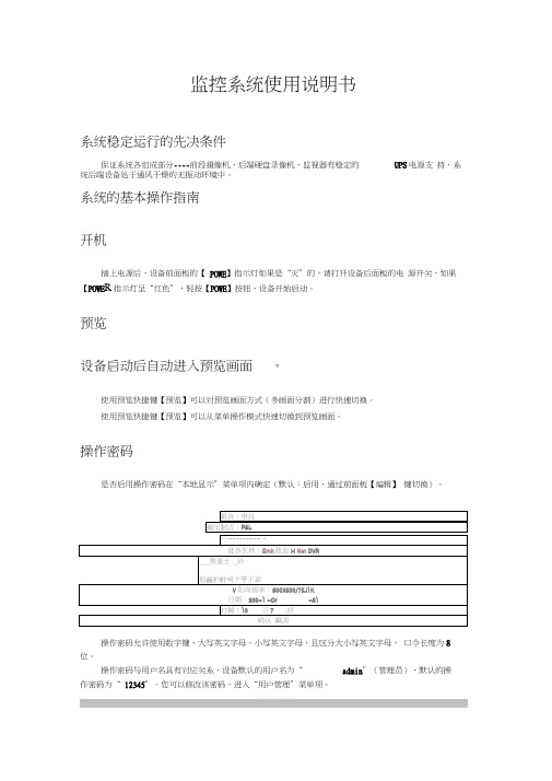
通过前面板【录像】键直接进入手动录像操作界面。
手动录像
通道;113 4 5 61B4 101L12 13 14
戟蛊:档密淫盘1J1密魯点曲曲密罚自虫檜曲
启/ 特:EJ/ / / / 1/ / / / / I/ / / / /V
全部启动全』:Jr
通道状态
总表示处于空闲 绿色灯表示正在录像 红色灯表示正在网传 橙色灯表示既在录像又在网传。
___熬蚤土_砂
垠繭护軒呵?〒不乖
V阳命搭率:800X600/75J1K
日期:200-1 -Or-21
时御;10沼7:抒
确认 飙消
操作密码允许使用数字键、大写英文字母、小写英文字母,且区分大小写英文字母, 口令长度为8位。
操作密码与用户名具有对应关系,设备默认的用户名为“admin”(管理员),默认的操
2003-12-Q907: 33; 46
2A0J-12-O907: 10: 58
2C03-12-0906:48: 10
2003-12-0906; 25; 22
2004-12-0906: 02:U2仙4-12-09 Q5:39:46
视频剪辑:在回放录像资料的过程中,通过【编辑】键启动和停止视频片段的剪辑,剪辑的 画面保存在USB存储设备中。
回放方式
时间检索,文件播放:输入起止时间,使时间检索有效(使之处于“”状态,默认)
选择“搜索文件”,按【确认】键,列出文件列表(最多列出200个文件,通过“选择页号” 进行翻页),选择要回放的文件,【确认】开始播放。
返迸:通逍.]丸炼类型:金邯
走土:20Q3-12-0900:00:00今2003-12-Q923:59:59lZ
关机
通过菜单
XMS系列转速、线速、频率显示仪表 使用说明书

XMS 系列转速、线速、频率显示仪表使用说明书一、概述XMS 系列仪表采用了多项国际先进技术,具备宽范围输入的开关电源,输入信号测量采用测周期的方法,精确稳定,仪表全面采用表面贴装工艺,并采用多重保护和隔离设计,抗干扰能力强、可靠性高。
XMS 系列仪表具有多类型输入功能,一台仪表可以配接不同的输入信号, 大大减少了备表的数量。
其适用范围非常广泛,可与各类光电脉冲、齿码盘磁感应信号、4~20mA 两线制脉冲、标准TTL 脉冲信号等各种速度传感器配合使用,实现对转速、线速或脉冲信号的测量显示、报警控制、数据采集和记录。
XMS 系列仪表硬件上采用了模块化设计,增强了仪表的使用灵活性,便于用户扩展仪表的输出功能,仪表可选配1~4个继电器报警输出,还可选配变送输出,或标准通讯接口(RS485或RS232)。
XMS 系列仪表还具有零点和满度修正、数字滤波、传感器故障处理、打印接口、通讯接口、开关量输入、开关量输出等扩展功能。
二、技术规格信号幅度:50mV~10V、5~32V、4~20mA 共三档输入频率:0.1~10000Hz 显示范围:-1999~9999 测量精度:0.1级(±0.1%FS)报警输出:继电器触点开关输出(常开+常闭),触点容量220VAC/2A 或24VDC/2A报警精度:±1定义单位变送范围:0~22mA、0~10VDC 变送精度:0.3级(±0.3%FS)通讯接口:RS485串行通讯接口、RS232C 串行通讯接口外供电源:24VDC 或12VDC(25mA)使用环境:环境温度0~50℃,相对湿度 ≤85%,避免强腐蚀气体电 源:开关电源 100~240VAC(50Hz/60Hz);开关电源24VDC/AC±10%功 耗:≤5W 重 量:≤1000g三、仪表接线1、XMS-1/-2型仪表接线图四、仪表说明1、显示说明2、操作说明(1)上电过程按接线图进行正确接线,检查无误后上电。