车辆工程毕设英文翻译
车辆工程毕业设计---英文翻译

车辆工程专业英文翻译原文:The controllable suspension system can improve both ride comfort and handling safety, which has become one research focus in the field of vehicle engineering since1950s.The full-car generally consists of four quarter-car suspension systems(QC)withstrong coupling characteristics,which yield strong coupling effects on vertical,pitch androll movement suspension performances.So far,an effective coordinated control methodfor the full-car with multiple sub-suspension systems has not been proposed.The best ideais to decouple the full-car into four independent QCs1,such that the sophisticated active orsemi-active control scheme for QC suspension can be directly employed,and thus simplifythe complicated controller synthesis for the full-car suspension and improve the real-timeproperty of control system,which has important theoretical and engineering values forrealizing the practical application of controllable suspension.This thesis focuses on the structural decoupling control study of half-car suspension,which has vertical and pitch movements.Firstly,the passive half-car dynamic model isestablished and transferred into the model involving two similar standard QC dynamicmodels.It is found that a coupling damping force exists in the sprung mass,and it can becompensated through adding a damping force in the unsprung mass, in which the half-carsuspension could be decoupled into two independent QCs.Furthermore,a new QCsuspension design with double controllable dampers is proposed on basis of the definedcoupling damping force,in which the traditional passive damper is normally replaced bythe sprung controllable dampe.Another damper named the unsprung controllable damperis installed between the lower control arm and linkage of vehicle controlled by the pitchangular acceleration,which plays role in compensating the yielded coupling damping force.Thus the suspension structural decoupling of half-car can be conveniently achieved and effectiveness of the proposed structural decoupling method of half-car suspension is verified.Finally,three kinds of control manners i.e.,active versus active,semi-activeversus active and semi-active versus semi-active,are fully discussed for the sprung and unsprung controllable dampers,respectively.The proposed active and semi-active slidingmode control schemes for the sprung controllable damper in QC are applied for thedecouplinghalf-car suspension robust control due to the uncertainty of vehicle load,andhe semi-active control manner chooses the semi-active controllable magneto-rheologicaldamper.As a result, the proposed both active versus active and semi-active versus active control manners could achieve the ideal multi-objective suspension performances for thehalf-car,and the proposed structural decoupling control method can be further extended to realize coordinated control of full-vehicle suspension system with multiple sub-suspension.Engineering vehicles working condition is usually relatively poor,coupled with thelimitations of the performance of the vehicle suspension system.It makes these vehicles' driveralways in the vibration of the high strength,and influences the driver's work efficiency,seriously hurts to the driver's spine,and directly leads to the disease.In order to reducevibration to the driver,this thesis usually takes the seat suspension system to isolate vibration,and uses the appropriate control strategies for seat suspension.It can effectively attenuate thevibration caused by uneven ground,reduce the vibration energy passed on to the driver's body,and improve the drivers'ride comfort.Magneto-rheological fluid is a kind of intelligent material,which has good rheologicalproperties.It can be the first choice of the semi-active suspension shock absorber material.According to the characteristics of magneto-rheological fluid,it can be made a lot of productswhich are used in mechanical engineering,civil engineering,etc.The most prominent exampleis magneto-rheological damper for vibration control in cable suspension bridge vibration,high-rise isolation,etc.In addition,the magnetic fluid rheostat vibration application of suspensionsystem is an important domain,including vehicle suspension system and vehicle seatsuspension system.In the suspension of the magneto-rheological damper applications,it ismainly for dissipation produced by the road excitation of vehicle and driver's vibration energy,to improve the ride comfort.Due to its good controllability,wide dynamic range,fast response,low power requirement and comparatively simple structure,magnetorheological(MR)dampers has become one of the focus research projects in automotive semi-active suspension.Besides damping force and dynamic range,the dynamic response is another important parameter of MR dampers,which isa key part of automotive MR semi-active suspension system.The dynamic response is valuable because it is one of the critical factors that determine the practical effectiveness of automotive MR dampers,the applications range of MR dampers and the controlling period directly.In this thesis,the dynamic response of automotive MR dampers is investigated and the effects of various conditions are considered.The main contributions include the following:(1)The properties and applications of MR fluid is reviewed firstly,the importance of the study on MR dampers dynamic response is discussed,and the present situation and existing problems of the study are summarized.Based on the present problems of the study,the main work is put forward.(2)Based on the hydrodynamics theory and working modes of MR dampers,applying the constitutive equations of Newton and Bingham fluid respectively,the parallel plates and annular duct based rheological equations are derived,the calculation approach of damping force is gained,and the theoretical relation between applied current,piston velocity and damping force is determined,which establishes he theoretical basis for the research of MR dampers dynamic response,propose of test approach and design of test system.Based on theoretical analysis of damping force,the calculation model of MR dampers dynamic response is built by analyzing the unstable state of MR fluid between parallel plates.Furthermore, driving by current source,the effect of the connecting way(parallel or serial)of electromagnetic coils is analyzed theoretically.(3)According to the damping force function and practical condition of dampers,an experimental approach for finding the dynamic response of automotive MR dampers and corresponding data processing are offered,the corresponding test system is developed, including some important parts of the test system,such as current driver based on PWM method,and its output characteristic and dynamic response are investigated theoretically and experimentally.译文:可控悬架系统能够同时提高车辆驾乘舒适度与操控安全性,因而具有出色的综合悬架性能,从上世纪五十年代起,就是国际车辆工程领域的研究热点课题之一。
汽车专业毕业设计外文翻译

附录:英汉对照Automotive oxygen sensor failure andinspection of the commonThe automotive industry is currently in the international application of the sensor on one of the largest markets, and the oxygen sensor reported the number of patents, ranking the first in automotive sensors. Oxygen sensor installed in the vehicle exhaust pipe, use it to detect the oxygen content in exhaust port. Oxygen sensor and thus can be obtained in accordance with the signal, put it back to the control system tofine-tune the fuel injection, so that A / F control at best, not only greatly reduces emissions and saves energy. At present, the practical application of the oxygen sensor has zirconia dioxide oxygen sensors and the two oxygen sensors. And common oxygen sensor and a single lead, double-lead and lead of three points; single pin for Zirconia oxygen sensor; double lead for the titanium dioxide oxygen sensor;three-lead type for the heating oxygen zirconia sensors, in principle, lead the way on three of the oxygen sensor is not a substitute for use. Are one of the most widely used type of zirconia oxygen sensor.First, zirconia oxygen sensor structureIn the use of three-way catalytic converters to reduce exhaust pollution on the engine, oxygen sensors are essential components. Oxygen sensor is located in the first section of the exhaust pipe, catalytic converter at the front. There is a Oxygen Sensor zirconia (a ceramic) components manufacturers, all of its outside has a layer ofthin-plated platinum. Zirconia ceramic plated body at one end with a thin layer of platinum closed. Into the protection of the latter was set, and installed in a metal body. Further protect the protection of the role of sets played and sensor can be installed on the exhaust manifold. Ceramic exhaust external exposure, and the internal atmosphere and the environment the same.This component has a very high temperature resistance, low temperature so do not allow current through. However, when high temperature, because of the air and exhaust gas oxygen concentration difference, oxygen ions can, through this component. This raises the potential difference, platinum to enlarge. In this way,air-fuel ratio lower than the theoretical air-fuel ratio (thick), the components in the oxygen sensor in (air) outside (the atmosphere) between the oxygen concentration has a greater bad. Thus, the sensors have a relatively strong one voltage (Johnson V). On the other hand, if the rare gas mixture, air and exhaust gas oxygen concentration difference between the very small, have a sensor, there is only one relatively weak voltage (near 0 volts).Because once the mixture of air-fuel ratio deviation from the theoretical air-fuel ratio, ternary catalysts for CO, HC and NOX purification capacity will be a sharp decline, it is installed at the exhaust pipe oxygen sensor for detecting oxygen concentration in the exhaust, and ECU the issue of feedback signal, and then by theECU to control fuel injection amount of injector change, which will control the mixture at the air-fuel ratio near the theoretical value.Two, automotive oxygen sensor working principleOxygen sensor installed in the exhaust manifold, it can detect the concentration of oxygen in the exhaust, air-fuel ratio calculated, and the results sent to the ECU.For example:1, exhaust gas oxygen concentration in the high –When emissions are significant when the percentage of oxygen, ECU will accordingly determine the air-fuel ratio, and that is very dilute mixture.2, exhaust gas oxygen concentration in the low –When the percentage of oxygen in the exhaust very, ECU to determine air-fuel ratio will accordingly small, that is very strong mixture. Temperature higher than300 ℃, the ceramic materials used for the iron conductor. Under these conditions, if the percentage of oxygen sensors on both sides of the different content will have a voltage change at both ends. Two types of environment (air-side and exhaust side) of the different measurements of the oxygen content of these changes tell ECU, exhaust at the oxygen content in the remainder of the generation of harmful emissions to ensure that combustion is not appropriate percentage. Ceramic materials at temperatures lower than 300 ℃are non-linear, and thus the sensor is not a useful signal transmission. ECU has a special function, that is, heating machine at pm (open-loop operation) to stop the adjustment of the mixture. Sensors equipped with heating elements to reach operating temperature quickly. When current flows through the heating elements, it reduces the iron to make ceramics become conductors of time, and which makes the sensor can be installed in the exhaust pipe of the site later.In the three-way catalytic purifier Medium, ECU using data from the oxygen sensor to regulate the air-fuel ratio, but the method of standard Carburetor EFI device somewhat different.At EFI device, EFI's ECU fuel injection through the increase or decrease from the injected fuel volume, adjusting air-fuel ratio. If the ECU from the oxygen sensor detects the mixture too thick, it will gradually reduce the amount of fuel injection, the mixture of on-thinning. Therefore the actual air-fuel ratio becomes greater than the theoretical air-fuel ratio (more dilute). When this happens, ECU through the oxygen sensor to detect the truth, it will start a gradual increase in the volume of spray. In this way, air-fuel ratio is too low, some will Luan (more dense) until the air-fuel ratio lower than the theoretical. Thus, the cycle repeated, ECU main cloud in this way, constant changes in air-fuel ratio, the actual air-fuel ratio near the theoretical air-fuel ratio.Carburetor in the use of the device, are entered by regulating air intake air-fuel ratio of air-conditioning. Mixture theory is usually air-fuel ratio to maintain a little thick. ECU within the air-fuel ratio oxygen sensor has been the information, and manipulation, according to the actual air-fuel ratio EBCU (electronically controlled intake valve) regulator into the carburetor air intake volume. If mixture is too strong, it allows more air to enter to-thinning: If mixture is too thin, it allows less air to enter,so that moreThird, the common automotive oxygen sensor faultOnce the oxygen sensor fails, the electronic fuel injection system will enable the computer should not be the oxygen concentration in the exhaust pipe of the information, and therefore should not be on the air-fuel ratio feedback control, the engine will increase fuel consumption and exhaust pollution, engine idle speed instability, lack of fire, such as fault-surge situation. Therefore, it is necessary to troubleshoot in a timely manner or replaced.1, oxygen sensor poisoningOxygen sensor poisoning and are often more difficult to control emerging as a fault, in particular, are often the use of leaded petrol cars, even the new oxygen sensor, and can only be the work of thousands of kilometers. If only minor lead poisoning, and then use a box of unleaded petrol, will be able to eliminate the surface of oxygen sensor lead to the resumption of normal work. But often because of excessive exhaust temperature, which lead intrusion in their internal and impede the spread of oxygen ions to oxygen sensor failure can only be replaced at this time.In addition, the oxygen sensor silicon poisoning happened is common. In general, gasoline and lubricants containing silicon compounds generated by combustion silica, silicon rubber seal gasket improper use of silicone emitting gas,will cause the oxygen sensor failure, and therefore want to use good quality fuel and lubricants .Right to choose the repair and installation of rubber gaskets, coated on the sensor not to require the use of factory and other than the anti-solvent, etc.2, carbon depositionNot because of engine combustion, in the carbon deposition formed on the surface of oxygen sensor, oxygen sensor or the internal into the sediment, such as oil or dust will impede or block the external air into the oxygen sensor internal to oxygen sensor signal output inaccurate, ECU should not timely correct air-fuel ratio. Soot produced, mainly for increased fuel consumption, emission levels were significantly increased. At this point, if the sediment removal will restore normal working.3, oxygen sensor ceramic fragmentsCeramic oxygen sensor hardware and crisp, with a hard object by knocking or washing with a strong air currents blowing all its fragmentation and possible failure. Therefore, be particularly careful when handling and found that the timely replacement of problem.4, heater resistance wire blownThe heating-type oxygen sensor, if the resistance heater wire ablation, it is difficult to make sensors to reach normal operating temperature and the loss of role.5, oxygen sensor breaking off the internal circuits.Four, automotive oxygen sensor method1, oxygen sensor heater resistance checkUnplug the oxygen sensor wiring harness plug, use a multimeter resistance measurement file in the oxygen sensor heater terminal access-chu-chu with Ground between access resistance and its resistance to 4-40Ω (refer to specific modelspecification). Such as not meeting the standard, should be the replacement of oxygen sensor.2, oxygen sensor voltage feedback measurementMeasurement of oxygen sensor feedback voltage should unplug the oxygen sensor wiring harness plug, the control circuit models, the feedback from the oxygen sensor voltage output terminal on a thin wire leads, and then plug harness plugs well, in the engine operation , measured from the pinout on the feedback voltage (some models can also be inner socket fault detection by a voltage of oxygen sensor feedback, such as the production of Toyota cars can be a series of fault detection from the socket terminal OX1 or OX2 directly measured oxygen sensor feedback voltage). Oxygen sensor feedback on the test voltage, it is best to use with low-range (typically 2V) and high impedance (resistance greater than 10MΩ) multimeter pointer type. Detection of specific methods are as follows: 1) hot cars engine to normal operating temperature (or after the start-up speed of 2500r/min running 2min); 2) will file a negative voltage multimeter table T then fault detection within the socket or the battery negative electrode E1 is fault detection table T then the socket jack OX1 or OX2, or receive oxygen sensor wiring harness plug on the No. | round; 3) to allow the engine to maintain speed around 2500r/min operation voltage meter at the same time check whether the pointer back and forth between 0-1V swing, with a note of voltage meter pointer 10s the number of swing. Under normal circumstances, with the feedback control, the oxygen sensor feedback voltage will be 0.45V at changing up and down, 10s in the number of feedback voltage changes should not be less than 8 times. If less than 8 times, then oxygen sensor feedback control system or not working properly because the surface of oxygen sensor are possible there is carbon deposition, so that lower sensitivity. In this regard, should be allowed to 2500r/min engine speed operation of about 2min, to clear the surface of the carbon deposition oxygen sensor, and then check the feedback voltage. If the removal of carbon deposition may change after the voltage meter pointer is still slow, then oxygen sensor damaged, or have computer feedback control circuit fault. 4) check whether the damaged oxygen sensor Unplug the oxygen sensor wiring harness plug, so that oxygen sensor is no longer connected with the computer, feedback control system is in a state ofopen-loop control. The multimeter voltage pen table file is directly related to oxygen sensor feedback voltage output terminal connected to the negative form of good Ground pen. Measurement of engine operation at the feedback voltage, the first intake pipe was torn off and then up at the mandatory crankcase ventilation hose vacuum tube or other artificially dilute the mixture to form, at the same time watch voltage meter, the pointer should be dropped readings. Was torn off and then connected to the pipeline, and then unplug the water temperature sensor connector, a 4-8KΩ in place of the resistance temperature sensor, the formation of artificially dense mixture, at the same time watch voltage meter, the indicator reading should be increased. Can also be used, or a sudden release the accelerator pedal down approach to change the concentration of the mixture, in sudden pedal down to accelerate, the mixture变浓, feedback voltage should be increased; sudden release when the accelerator pedal,mixed gas-thinning, feedback voltage should be decreased. If the oxygen sensor feedback voltage without the above changes show that the oxygen sensor has been damaged. In addition, the titanium dioxide-type oxygen sensor using the above method at the time, if a good oxygen sensor output voltage to 2.5V as the center should be up and down fluctuations. Otherwise, the sensor can be removed and exposed to the air, cooling the resistance value after the measurement. If a large resistance value that sensor is ok, or should replace the sensor. 5) oxygen sensor to check the color appearance Removed from the exhaust pipe on oxygen sensors, sensors to check whether the shell to plug up the vents, ceramic core whether or not broken. If damaged, replace the oxygen sensor should be. By observing the top part of the oxygen sensor can also determine the color breakdown:①light gray top: This is the normal color of the oxygen sensor; ②white top: pollution from silicon, oxygen sensor must be replaced at this time; ③brown top: pollution by lead, if serious, we must replace the oxygen sensor; ④black top: caused by carbon deposition, carbon deposition in the exclusion of engine failure, the general oxygen sensor can automatically clear up the accumulatedcarbon. Conclusion: for energy conservation and the prevention of pollution from motor vehicles, most developed countries in the West aerobic sensors installed on my car is loaded oxygen sensor must be used. China's automobile industry with foreign countries, one of the main gap, but also in automotive sensors. Therefore, we can come to promote the use of oxygen sensor is very optimistic about the prospects.汽车氧传感器的常见故障及检查汽车行业是目前在国际上应用传感器最大的市场之一,而氧传感器申报的专利数,居汽车传感器的首位。
车辆工程专业毕业论文_外文翻译
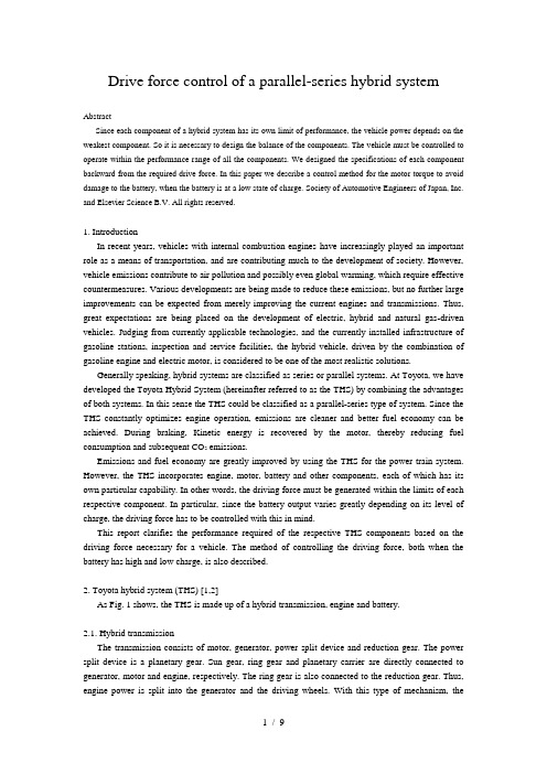
Drive force control of a parallel-series hybrid systemAbstractSince each component of a hybrid system has its own limit of performance, the vehicle power depends on the weakest component. So it is necessary to design the balance of the components. The vehicle must be controlled to operate within the performance range of all the components. We designed the specifications of each component backward from the required drive force. In this paper we describe a control method for the motor torque to avoid damage to the battery, when the battery is at a low state of charge. Society of Automotive Engineers of Japan, Inc. and Elsevier Science B.V. All rights reserved.1. IntroductionIn recent years, vehicles with internal combustion engines have increasingly played an important role as a means of transportation, and are contributing much to the development of society. However, vehicle emissions contribute to air pollution and possibly even global warming, which require effective countermeasures. Various developments are being made to reduce these emissions, but no further large improvements can be expected from merely improving the current engines and transmissions. Thus, great expectations are being placed on the development of electric, hybrid and natural gas-driven vehicles. Judging from currently applicable technologies, and the currently installed infrastructure of gasoline stations, inspection and service facilities, the hybrid vehicle, driven by the combination of gasoline engine and electric motor, is considered to be one of the most realistic solutions.Generally speaking, hybrid systems are classified as series or parallel systems. At Toyota, we have developed the Toyota Hybrid System (hereinafter referred to as the THS) by combining the advantages of both systems. In this sense the THS could be classified as a parallel-series type of system. Since the THS constantly optimizes engine operation, emissions are cleaner and better fuel economy can be achieved. During braking, Kinetic energy is recovered by the motor, thereby reducing fuel consumption and subsequent CO2 emissions.Emissions and fuel economy are greatly improved by using the THS for the power train system. However, the THS incorporates engine, motor, battery and other components, each of which has its own particular capability. In other words, the driving force must be generated within the limits of each respective component. In particular, since the battery output varies greatly depending on its level of charge, the driving force has to be controlled with this in mind.This report clarifies the performance required of the respective THS components based on the driving force necessary for a vehicle. The method of controlling the driving force, both when the battery has high and low charge, is also described.2. Toyota hybrid system (THS) [1,2]As Fig. 1 shows, the THS is made up of a hybrid transmission, engine and battery.2.1.Hybrid transmissionThe transmission consists of motor, generator, power split device and reduction gear. The power split device is a planetary gear. Sun gear, ring gear and planetary carrier are directly connected to generator, motor and engine, respectively. The ring gear is also connected to the reduction gear. Thus, engine power is split into the generator and the driving wheels. With this type of mechanism, therevolutions of each of the respective axes are related as follows. Here, the gear ratio between the sun gear and theFig. 1. Schematic of Toyota hybrid system (THS).ring gear is ρ:where Ne is the engine speed, Ng the generator speed and Nm the motor speed.Torque transferred to the motor and the generator axes from the engine is obtained as follows:where Te is the engine torque.The drive shaft is connected to the ring gear via a reduction gear. Consequently, motor speed and vehicle speed are proportional. If the reduction gear ratio isη, the axle torque is obtained as follows:where Tm is the motor torque.As shown above, the axle torque is proportional to the total torque of the engine and the motor on the motor axis. Accordingly, we will refer to motor axis torque instead of axle torque.2.2. EngineA gasoline engine having a displacement of 1.5 l specially designed for the THS is adopted [3]. This engine has high expansion ratio cycle, variable valve timing system and other mechanisms in order to improve engine efficiency and realize cleaner emissions. In particular, a large reduction in friction is achieved by setting the maximum speed at 4000 rpm (=Ne max).2.3. BatteryAs sealed nickel metal hydride battery is adopted. The advantages of this type of battery are high power density and long life. this battery achieves more than three times the power density of those developed for conventional electric vehicles [4].3. Required driving force and performanceThe THS offers excellent fuel economy and emissions reduction. But it must have the ability to output enough driving force for a vehicle. This section discusses the running performance required of the vehicle and the essential items required of the respective components.Road conditions such as slopes, speed limits and the required speed to pass other vehicles determine the power performance required by the vehicle. Table 1 indicates the power performance needed in Japan.3.1. Planetary gear ratioρThe planetary gear ratio (ρ) has almost no effect on fuel economy and/or emissions. This is because the required engine power (i.e. engine condition) depends on vehicle speed, driving force and battery condition, and not on the planetary gear ratio. Conversely, it is largely limited by the degree of installability in the vehicle and manufacturing aspects, leaving little room for design. In the currently developed THS, ρ=0.385.3.2. Maximum engine powerSince the battery cannot be used for cruising due to its limited power storage capacity, most driving is reliant on engine power only. Fig. 2 shows the power required by a vehicle equipped with the THS, based on its driving resistance. Accordingly, the power that is required for cruising on a level road at 140 km/h or climbing a 5% slope at 105 km/h will be 32 kW. If the transmission loss is taken into account, the engine requires 40 kW (=Pe max) of power. The THS uses an engine with maximum power of 43 kW in order to get good vehicle performance while maintaining good fuel economy.3.3. Maximum generator torqueAs described in Section 2, the maximum engine speed is 4000 rpm (=Ne max). To attain maximum torque at this speed, maximum engine torque is obtained as follows:From Eq. (3), the maximum torque on the generator axis will be as follows:This is the torque at which the generator can operate without being driven to over speed. Actually, higher torque is required because of acceleration/deceleration of generator speed and dispersion of engine and/or generator torque. By adding 40% torque margin to the generator, the necessary torque is calculated as follows:3.4. Maximum motor torqueFrom Fig. 3, it can be seen that the motor axis needs to have a torque of 304 Nm to acquire the 30% slope climbing performance. This torque merely balances the vehicle on the slope. To obtain enough starting and accelerating performance, it is necessary to have additional torque of about 70 Nm, or about 370 Nm in total.From Eq. (2), the transmitted torque from the engine is obtained as follows:Consequently, a motor torque of 300 Nm (=T m max) is necessary.3.5. Maximum battery powerAs Fig. 2 shows, driving power of 49 kW is needed for climbing on a 5%slope at 130 km/h. Thus, the necessary battery power is obtained by subtracting the engine-generated power from this. As already discussed, if an engine having the minimum required power is installed, it can only provide 32 kW of power, so the required battery power will be 17 kW. If the possible loss that occurs when the battery supplies power to the motor is taken into account, battery power of 20 kW will be needed. Thus, it is necessary to determine the battery capacity by targeting this output on an actual slope. Table 2 lists the required battery specifications.Table 3 summarizes the specifications actually adopted by the THS and the requirements determined by the above discussion. The required items represent an example when minimum engine power is selected. In other words, if the engine is changed, each of the items have to be changed accordingly.4. Driving force controlThe THS requires controls not necessary for conventional or electric vehicles in order to controlthe engine, motor and generator cooperatively. Fig. 4 outlines the control system.Fig. 4. Control diagram of the THS.Inputs of control system are accelerator position, vehicle speed (motor speed), generator speed and available battery power. Outputs are the engine-required power, generator torque and motor torque.First, drive torque demanded by the driver (converted to the motor axis) is calculated from the accelerator position and the vehicle speed. The necessary drive power is calculated from this torque and the motor speed. Required power for the system is the total of the required drive power, the required power to charge the battery and the power loss in the system. If this total required power exceeds the prescribed value, it becomes required engine power. If it is below the prescribed value, the vehicle runs on the battery without using the engine power. Next, the most efficient engine speed for generating engine power is calculated; this is the engine target speed. The target speed for the generator is calculated using Eq. (1) with engine target speed and motor speed. The generator torque is determined by PID control. Engine torque can be calculated in reverse by using Eq. (3) and the torque transferred from the engine to the motor axis can be calculated from (2). The motor torque is obtained by subtracting this torque from the initially calculated drive torque. Since it is not possible to produce a torque whereby the motor consumption power exceeds the total of the generator-generated power and the power supplied by the battery, it is necessary to control the motor power (torque) within this total power. Fig. 5 shows the control method. The sum of the power form the generator and the available battery power become the power that can be used by the motor. The available motor torque can be obtained by dividing this combined power by the motor speed. When the motor speed is low, if the calculated motor torque exceeds the motor specification of torque the motor torque is determined by the specification. By controlling the motor torque requirement with this limited torque, the motor consumption power can be controlled to within the available power. If the available battery power is large enough, the available motor torque hardly limits the motor torque. Conversely, when the charge is low, the motor torque is frequently limited.Fig. 6 shows the respective maximum drive torque of the battery, the engine, and the engine plus the battery while running based on the controls above, when the THS has the components as specified in Section 3.5. ConclusionsThis paper discussed the control of drive power in the Toyota Hybrid System. The following conclusions were obtained:●The performance required for each component can be determined by reversely calculating powerperformance required for a vehicle.●The available battery power varies according to its state of charge. However, by limiting themotor torque, the battery power can be controlled to within the battery's available power.混合动力系统驱动力的串并联控制摘要由于混合动力系统的每个部分都有自己的极限性能,所以汽车动力取决于最脆弱的哪一个组成部分。
毕业设计论文外文文献翻译汽车专业汽修点火系统中英文对照
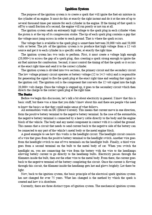
Ignition SystemThe purpose of the ignition system is to create a spark that will ignite the fuel-air mixture in the cylinder of an engine. It must do this at exactly the right instant and do it at the rate of up to several thousand times per minute for each cylinder in the engine. If the timing of that spark is off by a small fraction of a second, the engine will run poorly or not run at all.The ignition system sends an extremely high voltage to the spark plug in each cylinder when the piston is at the top of its compression stroke. The tip of each spark plug contains a gap that the voltage must jump across in order to reach ground. That is where the spark occurs.The voltage that is available to the spark plug is somewhere between 20,000 volts and 50,000 volts or better. The job of the ignition system is to produce that high voltage from a 12 volt source and get it to each cylinder in a specific order, at exactly the right time.The ignition system has two tasks to perform. First, it must create a voltage high enough (20,000+) to across the gap of a spark plug, thus creating a spark strong enough to ignite the air/fuel mixture for combustion. Second, it must control the timing of that the spark so it occurs at the exact right time and send it to the correct cylinder.The ignition system is divided into two sections, the primary circuit and the secondary circuit. The low voltage primary circuit operates at battery voltage (12 to 14.5 volts) and is responsible for generating the signal to fire the spark plug at the exact right time and sending that signal to the ignition coil. The ignition coil is the component that converts the 12 volt signal into the high 20,000+ volt charge. Once the voltage is stepped up, it goes to the secondary circuit which then directs the charge to the correct spark plug at the right time.The BasicsBefore we begin this discussion, let’’s talk a bit about electricity in general. I know that this is Before we begin this discussion, letbasic stuff, but there was a time that you didn’’t know about this and there are people who need basic stuff, but there was a time that you didnto know the basics so that they could make sense of what follows.All automobiles work on DC (Direct Current). This means that current move in one direction, form the positive battery terminal to the negative battery terminal. In the case of the automobile, the negative battery terminal is connected by a heavy cable directly to the body and the engine block of the vehicle. The body and any metal component in contact with it is called the ground. This means that a circuit that needs to send current back to the negative side of the battery can be connected to any part of the vehicle’’s metal body or the metal engine block.be connected to any part of the vehicleA good example to see how this works is the headlight circuit. The headlight circuit consists of a wire that goes from the positive battery terminal to the headlight switch. Another wire goes from the headlight switch to one of two terminals on the headlight bulb. Finally, a third wire goes from a second terminal on the bulb to the metal body of car. When you switch the headlight on, you are connecting the wire from the battery with the wire to the headlamps allowing battery current to go directly to the headlamp bulbs. Electricity passes through the filaments inside the bulb, then out the other wire to the metal body. From there, the current goes back to the negative terminal of the battery completing the circuit. Once the current is flowing through this circuit, the filament inside the headlamp gets hot and glows brightly. Let there be light.Now, back to the ignition system, the basic principle of the electrical spark ignition system has not changed for over 75 years. What has changed is the method by which the spark is created and how it is distribute.Currently, there are three distinct types of ignition system. The mechanical ignition systemwas used prior to 1975. It was mechanical and electrical and used no electronics. By understanding these early system, it will be easier to understand the new electronic andcomputer controlled ignition system, so don’’t skip over it. The electronic ignition system started computer controlled ignition system, so donfinding its way to production vehicles during the early 70s and became popular when better control and improved reliability became important with the advent of emission controls. Finally, the distributor less ignition system became available in the mid 80s. This system was always computer controlled and contained no moving parts, so reliability was greatly improved. Most of these systems required no maintenance except replacing the spark plugs at intervals from 60,000 to over 100,000 miles.Let’’s take a detailed look at each system and see how they work.LetThe Mechanical Ignition SystemThe distributor is the nerve center of the mechanical ignition system and has two tasks to perform. First, it is responsible for triggering coil to generate a spark at the precise instant that it is required (which varies depending how fast the engine is turning and how much load it is under). Second, the distributor is responsible for directing that spark to the proper cylinder (which is why it is called a distributor).The circuit that powers the ignition system is simple and straight forward. When you insert the key in the ignition switch and turn the key to the Run position, you are sending current from the battery through a wire directly to the positive (+) side of the ignition coil. Inside the coil is a series of copper windings that loop around the coil over a hundred times before exiting out the negative (-) side of the coil. From there, a wire takes this current over to the distributor and is connected to a special on/off switch, called the points. When the points are closed, this current goes directly to ground. When current flows from the ignition switch, through the windings in the coil, then to ground, it builds a strong magnetic field inside the coil.The points are made up of a fixed contact point that is fastened to a plate inside the distributor, and a movable contact point mounted on the end of a spring loaded arm. The movable point rides on a 4, 6, or 8 lobe cam (depending on the number of cylinder in the engine) that is mounted on a rotating shaft inside the distributor. This distributor cam rotates in time with the engine, making one complete revolution for every two revolutions of the engine. As it rotates, the cam pushes the points open and closed. Every time the points open, the flow of current is interrupted through the coil, thereby collapsing the magnetic field and releasing a high voltage surge through the secondary coil windings. This voltage surge goes out the top of the coil and through the high-tension coil wire.Now, we have the voltage necessary to fire the spark plug, but we still have to get it to the correct cylinder. The coil wire goes from the coil directly to the distributor cap. Under the cap is a rotor that is mounted on top of the rotating shaft. The rotor has a metal strip on the top that is in constant contact with the center terminal of the distributor cap. It receives the high voltage surge from the coil wire and sends it to the other end of the rotor which rotates past each spark plug terminal inside the cap. As the rotor turns on the shaft, it sends the voltage to the correct spark plug wire, which in turn sends it to the spark plug. The voltage enters the spark plug at the terminal at the top and travels down the core until it reaches the tip. It then jumps across the tip of the spark plug, creating a spark suitable to ignite the fuel-air mixture inside that cylinder. The description I just provided is the simplified version, but should be helpful to visualize the process, but we left out a few things that make up this type of ignition system. For instance, we didn’’t talk about the condenser that is connected to the point, nor did we talk about the system didnto advance the timing. Let’’s take a look at each section and explore it in more detail.to advance the timing. LetThe Ignition SwitchThere are two separate circuits that go from the ignition switch to the coil. One circuit runs through a resistor in order to step down the voltage about 15% in order to protect the points from premature wear. The other circuit sends full battery voltage to the coil. The only time this circuit is used is during cranking. Since the starter draws a considerable amount of current to crank the engine, additional voltage is needed to power the coil. So when the key is turned to the spring-loaded start position, full battery voltage is used. As soon as the engine is running, the driver releases the key to the run position which directs current through the primary resistor to the coil.On some vehicles, the primary resistor is mounted on the firewall and is easy to replace if it fails. On other vehicles, most notably vehicles manufactured by GM, the primary resister is a special resister wire and is bundled in the wiring harness with other wires, making it more difficult to replace, but also more durable.The DistributorWhen you remove the distributor cap from the top of the distributor, you will see the points and condenser. The condenser is a simple capacitor that can store a small amount of current. When the points begin to open the current, flowing through the points looks for an alternative path to ground. If the condenser were not there, it would try to jump across the gap of the point as they begin to open. If this were allowed to happen, the points would quickly burn up and you would hear heavy static on the car radio. To prevent this, the condenser acts like a path to ground. It really is not, but by the time the condenser is saturated, the points are too far apart for the small amount of voltage to jump across the wide point gap. Since the arcing across the opening points is eliminated, the points last longer and there is no static on the radio from point arcing.The points require periodic adjustments in order to keep the engine running at peek efficiency. This is because there is a rubbing block on the points that is in contact with the cam and this rubbing block wears out over time changing he point gap. There are two ways that the points can be measured to see if they need an adjustment. One way is by measuring the gap between the open points when the rubbing block is on the high point of the cam. The other way is by measuring the dwell electrically. The dwell is the amount, in degrees of cam rotation that the points stay closed.On some vehicles, points are adjusted with the engine off and the distributor cap removed. A mechanic will loosen the fixed point and move it slightly, then retighten it in the correct position using a feeler gauge to measure the gap. On other vehicles, most notably GM cars, there is a window in the distributor where a mechanic can insert a tool and adjust the points using a dwell meter while the engine is running. Measuring dwell is much more accurate than setting the points with a feeler gauge.Points have a life expectancy of about 10,000 miles at which time have to be replaced. This is done during a routine major tune up, points, condenser, and the spark plugs are replaced, the timing is set and the carburetor is adjusted. In some cases, to keep the engine running efficiently, a minor tune up would be performed at 5,000 mile increments to adjust the point and reset the timing.Ignition CoilThe ignition coil is nothing more that an electrical transformer. It contains both primary and secondary winding circuit. The coil primary winding contains 100 to 150 turns of heavy copper wire. This wire must be insulated so that the voltage does not jump from loop to loop, shortingit out. If this happened, it could not create the primary magnetic field that is required. The primary circuit wire goes into the coil through the positive terminal, loops around the primary windings, then exits through the negative terminal.The coil secondary winding circuit contains 15,000 to 30,000 turns of fine copper wire, which also must be insulated from each other. The secondary windings sit inside the loops of the primary windings. To further increase the coils magnetic field the windings are wrapped around a soft iron core. To withstand the heat of the current flow, the coil is filled with oil which helps keep it cool.The ignition coil is the heart of the ignition system. As current flows through the coil a strong magnetic field is build up. When the current is shut off, the collapse of this magnetic field to the secondary windings induces a high voltage which is released through the large center terminal. This voltage is then directed to the spark plugs through the distributor.Ignition Timing The timing is set by loosening a hold-down screw and rotating the body of the distributor. Since the spark is triggered at the exact instant that the points begin to open, rotating the distributor body (which the point are mounted on) will change the relationship between the position and the position of the distributor cam, which is on the shaft that is geared to the engine rotation.While setting the initial or base timing is important, for an engine to run properly, the timing needs to change depending on the speed of the engine and the load that it is under. If we can move the plate that the points are mounted on, or we could change the position of the distributor cam in relation to the gear that drives it, we can alter the timing dynamically to suit the needs of the engine.Ignition Wires These cables are designed to handle 20,000 to more than 50,000 volts, enough voltage to toss you across the room if you were to be exposed to it. The job of the spark plug wires is to get that enormous power to the spark plug without leaking out. Spark plug wires have to endure the heat of a running engine as well as the extreme changes in the weather. In order to do their job, spark plug wires are fairly thick, with most of that thickness devoted to insulation with a very thin conductor running down the center. Eventually, the insulation will succumb to the elements and the heat of the engine and begins to harden, crack, dry out, or otherwise break down. When that happens, they will not be able to deliver the necessary voltage to the spark plug and a misfire will occur. That is what is meant by “Not running on all cylinders cylinders””. To correct this problem, the spark plug wires would have to be replaced.Spark plug wires are routed around the engine very carefully. Plastic clips are often used to keep the wires separated so that they do not touch together. This is not always necessary, especially when the wires are new, but as they age, they can begin to leak and crossfire on damp days causing hard starting or a rough running engine.Spark plug wires go from the distributor cap to the spark plugs in a very specific order. This is called the is called the ““firing order firing order”” and is part of the engine design. Each spark plug must only fire at the end of the compression stroke. Each cylinder has a compression stroke at a different time, so it is important for the individual spark plug wire to be routed to the correct cylinder.For instance, a popular V8 engine firing order is 1, 8, 4, 3, 6, 5, 7, 2. The cylinders are numbered from the front to the rear with cylinder #1 on the front-left of the engine. So the cylinders on the left side of the engine are numbered 1, 3, 5, 7while the right side are numbered 2, 4, 6, 8. On some engine, the right bank is 1, 2, 3, 4 while the left bank is 5, 6, 7, 8. A repairmanual will tell you the correct firing order and cylinder layout for a particular engine.The next thing we need to know is what direction the distributor is rotating in, clockwise or counter-clockwise, and which terminal on the distributor caps that #1 cylinder is located. Once we have this information, we can begin routing the spark plug wires.If the wires are installed incorrectly, the engine may backfire, or at the very least, not run on all cylinders. It is very important that the wires are installed correctly.Spark PlugsThe ignition system system’’s sole reason for being is to service the spark plug. It must provide sufficient voltage to jump the gap at the tip of the spark plug and do it at the exact right time, reliably on the order of thousands of times per minute for each spark plug in the engine.The modern spark plug is designed to last many thousands of miles before it requires replacement. These electrical wonders come in many configurations and heat ranges to work properly in a given engine. The heat range of a spark plug dictates whether it will be hot enough to burn off any residue that collects on the tip, but not so hot that it will cause pre-ignition in the engine. Pre-ignition is caused when a spark plug is so hot, that it begins to glow and ignite the fuel-air mixture prematurely, before the spark. Most spark plugs contain a resistor to suppress radio interference. The gap on a spark plug is also important and must be set before the spark plug is installed in the engine. If the gap is too wide, there may not be enough voltage to jump the gap, causing a misfire. If the gap is too small, the spark may be inadequate to ignite a lean fuel-air mixture also causing a misfire.The Electronic Ignition SystemThis section will describe the main differences between the early point & condenser systems and the newer electronic systems. If you are not familiar with the way an ignition system works in general, I strongly recommend that you first read the previous section The Mechanical Ignition System.In the electronic ignition system, the points and condenser were replaced by electronics. On these systems, there were several methods used to replace the points and condenser in order to trigger the coil to fire. One method used a metal wheel with teeth, usually one for each cylinder. This is called an armature. A magnetic pickup coil senses when a tooth passes and sends a signal to the control module to fire the coil.Other systems used an electric eye with a shutter wheel to send a signal to the electronics that it was time to trigger the coil to fire. These systems still need to have the initial timing adjusted by rotating the distributor housing.The advantage of this system, aside from the fact that it is maintenance free, is that the control module can handle much higher primary voltage than the mechanical point. V control module can handle much higher primary voltage than the mechanical point. Voltage can oltage can even be stepped up before sending it to the coil, so the coil can create a much hotter spark, on the order of 50,000 volts that is common with the mechanical systems. These systems only have a single wire from the ignition switch to the coil since a primary resistor is not longer needed. On some vehicles, this control module was mounted inside the distributor where the points used to be mounted. On other designs, the control module was mounted outside the distributor with external wiring to connect it to the pickup coil. On many General Motors engines, the control module was inside the distributor and the coil was mounted on top of the distributor for a one piece unitized ignition system. GM called it high energy ignition or HEI for short.The higher voltages that these systems provided allow the use of a much wider gap on the spark plugs for a longer, fatter spark. This larger sparks also allowed a leaner mixture for betterfuel economy and still insure a smooth running engine.The early electronic systems had limited or no computing power, so timing still a centrifugal and vacuum advance built into the distributor.On some of the later systems, the inside of the distributor is empty and all triggering is performed by a sensor that watches a notched wheel connected to either the crankshaft or the camshaft. These devices are called crankshaft position sensor or camshaft position sensor. In these systems, the job of the distributor is solely to distribute the spark to the correct cylinder through the distributor cap and rotor. The computer handles the timing and any timing advance necessary for the smooth running of the engine.The Distributor Ignition SystemNewer automobiles have evolved from a mechanical system (distributor) to a completely solid state electronic system with no moving parts. These systems are completely controlled by the on-board computer. In place of the distributor, there are multiple coils that each serves one or two spark plugs. A typical 6 cylinder engine has 3 coils that are mounted together in a coil pack””. A spark plug wire comes out of each side of the individual coil and goes to the “packappropriate spark plug. The coil fires both spark plugs at the same time. One spark plug fires on the compression stroke igniting the fuel-air mixture to produce power while the other spark plug fires on the exhaust stroke and does nothing. On some vehicles, there is an individual coil for each cylinder mounted directly on top of the spark plug. This design completely eliminates the high tension spark plug wires for even better reliability. Most of these systems use spark plugs that are designed to last over 100,000 miles, which cuts down on maintenance costs.参考文献:[1] 王欲进,张红伟汽车专业英语[M]. 北京:北京大学出版社,中国林业出版社,2007.8,55—67点火系统点火系统的作用是产生点燃发动机气缸里可燃混合物的火花。
汽车专业毕业设计 翻译 中英文(全)automobile engine injection ignition -

Automobile Engine Injection and Ignition Using the Motorola MPC555 MicrocontrollerRick WagonerInformation Education and Technology 645, Section 001Professor Dr. Yudi GondokaryonoMay 2, 2006Automobile Engine Injection and IgnitionIntroductionAutomobile engines and powertrains have become a major growth area for microcontroller use. This growth is also expected to continue. As many new regulations concerning the exhaust emissions and fuel efficiency must be met then more and more microcontrollers on automobiles will be required. One area that currently makes use of a microcontroller is that of fuel injection and engine ignition.These two areas can both be controlled in a manner that can greatly increase fuel efficiency, lower exhaust emissions, and also improve engine power performance. Let’s begin by looking at fuel injection. Injecting the proper amount of fuel into the engine at the proper time allows the engine to operate a peak performance levels. This process can be accomplished without the use of a microcontroller. However, due to the many factors affecting what constitutes the proper amount and proper time makes the use of a microcontroller much more appealing. The microcontroller can gather the readings from sensors connected to many components on the engine to perform calculations determining the proper amount and proper time for the injection process to occur. The higher the temperature on the engine the better the fuel burns. As the fuel burns more efficiently less fuel is required to generate the same amount of energy. Having a temperature sensor on the motor providing input to the microcontroller allows for adjustment of the amount of fuel being injected into the motor to provide the same amount of engine output energy. These calculations are quite complex and thus would take some time for a person to perform. The microcontroller can gather the data, perform the calculations, and make the necessary adjustments in a fraction of a second. Thegathering and adjustment process can thus be performed many times per second allow for continuous levels of higher engine performance.Likewise, the ignition process can also be controlled in a similar process. Ignition needs to occur at a time that will allow the engine to provide the most energy for use. If the ignition is ‘fired’ exactly when the piston is at its highest point then energy will be lost. The amount of time that it takes for the ignition to fire and then travel to the piston allows the piston to move downward. Then when the fuel is ignited and the reaction takes place energy is not used to its full potential because the piston can not gain a full‘stroke’ from the reaction but rather is moved what distance is available thus operating at less than peak efficiency. However, if the ignition process is started slightly before the piston reaches its uppermost position the engine energy is thus used to its full potential. Again in this scenario a measurement must be taken and a calculation must be performed and then an adjustment made. The quicker this can be down the more efficient the engine will operate.For both injection and ignition there are many factors that will affect the outcome of the calculations required to adjust the engine into peak efficiency. As was discussed with the injection process, engine temperature plays a key role and engine speed greatly affects the ignition process. These factors are the key reason that a microcontroller is used instead of monitoring these elements manually. A person is simply incapable of keeping track of all of these factors and then also considering them in determining the proper adjustments to be made. This is why I will only assume a minor set of these factors for discussion in designing a basic microcontroller system to control both fuel injection and engine ignition.Our fuel injection system will take into account the temperature of the motor, the position of the accelerator pedal and the position of the crankshaft in determining when to open the injector and how long to leave it open. The engine ignition system will also consider the speed of the engine and the position of the crankshaft in determining when to trigger the spark control. By monitoring our four inputs: motor temperature, accelerator pedal, crankshaft position, and engine speed; we can properly adjust and synchronize our two output components: injectors and spark control.To meet the requirements of such a system I recommend using the Motorola MPC555 microcontroller. Following is a block diagram of the MPC555 followed by a list of features available on the microcontroller.MPC555 Features:PowerPC RISC processorPowerPC core with floating-point unit26 Kbytes fast RAM and 6 Kbytes TPU microcode RAM448 Kbytes flash EEPROM with 5-V programming5 V I/O systemSerial system – queued serial multi-channel module (QSMCM), dual CAN 2.0B controller modules (TouCAN )50-channel timer system – dual time processor units (TPU3), modular I/O system (MIOS1)32 analog inputs – dual queued analog-to-digital converters (QADC64)Submicron HCMOS (CDR1) technology272-pint plastic ball grid array (PBGA) packaging40-MHz operation with dual supply (3.3V, 5V)The MPC555 microcontroller is designed for the automotive industry and thus has been built with consideration for the extreme operating conditions that will be encountered by an automobile. The other key features that make this good choice for this application is the multiple analog-to-digital converters as well as the dual time processor units. Multiple converters allow multiple devices (engine speed sensor, accelerator pedal position, and motor position sensor) to be input simultaneously and have each analog signal converted to digital signals for further processing. Once our inputs have been recorded and converted then calculations can be performed to adjust our outputs. Another feature that enables the MPC555 to meet system requirements is the dual power supply voltages. The internal core runs at 3.3 V while the output ports operate at 5 V. This works well because the lower internal power consumption while providing necessary voltages for input and output devices. Most of the sensors and devices controlled by this type of microcontroller were designed to be compatible with older microcontrollers which only had a single power voltage supply which operated at 5 V. Since this is the case the 5 V I/O ports can operate with almost any available I/O device.Dual time processor units allow us to synchronize both output devices with a single microcontroller. A single time processor unit can be assigned to each output device; one for the spark control and one for the injection control. By adjusting the algorithm that takes in the input devices values and calculates the necessary output device levels we can adjust and control the timing of the spark and injection control. The time processor units both operate simultaneously with the CPU and thus have a single point of timing event triggers. The design of the time processor units allows processing of real-time hardware events without CPU intervention. This allows both output devices to be timed in unison to allow adjustment to the highest level of engine efficiency.The MPC555 was originally designed for automotive purposes and thus has been developed into an actual engine control unit. Mclaren Electronic Systems as built a device called the TAG-300 which provides the type of control described in this paper. The details of the TAG-300 can be found at/mes_pdf/Unit_Cont_TAG-300.pdf. Mclaren designed the TAG-300 for use in high-performance Formula 1 racing systems. Use in such a system indicates that the MPC555 meets the needs of high-performance automobiles and thus can also be used in today’s p ersonal automobiles. The Motorola MPC555 has been used for engine control and has many other possible applications in the automotive industry.ReferencesFIRE (2001). FI2RE – A Development Control Unit for Flexible Injection and Ignition.IVEZ Worldwide. Retrieved from/download.php;file=m01-01-09.pdf/dir=mtzqq/key=54d981bbb9b3582fae21f3346eed65fe on April 4, 2006. Microcontroller (2006). MPC555: an automotive PowerPC part. Retrieved from /campus/articles/motorola/motorola6%20extra.htm onApril 4, 2006.MPC555 (2000). MPC555/MPC556 User’s Manual. Freescale Semiconductor Inc.Retrieved from on April 4, 2006.TAG-300 (2006). Engine Control Unit TAG-300. Mclaren Electronics Systems.Retrieved from /mes_pdf/Unit_Cont_TAG-300.pdf on April 4, 2006.Transport (2004). Microcontrollers for the Automobile. Ross Bannatyne, Transportation Systems Group, Motorola, Inc. Retrieved from/aricles/arc105/arc105.htm on April 4, 2006汽车发动机喷射和点火使用摩托罗拉MPC555的微控制器里克瓦戈纳教育和科技信息645,第001教授博士堤Gondokaryono2006年5月2日汽车发动机喷射和点火导言汽车发动机和动力系统已成为微控制器的主要增长领域。
汽车专业--毕业设计外文翻译

英文资料SuspensionSuspension is the term given to the system of springs, shock absorbers and linkages that connects a vehicle to its wheels. Suspension systems serve a dual purpose –contributing to the car's roadholding/handling and braking for good active safety and driving pleasure, and keeping vehicle occupants comfortable and reasonably well isolated from road noise, bumps, and vibrations,etc. These goals are generally at odds, so the tuning of suspensions involves finding the right compromise. It is important for the suspension to keep the road wheel in contact with the road surface as much as possible, because all the forces acting on the vehicle do so through the contact patches of the tires. The suspension also protects the vehicle itself and any cargo or luggage from damage and wear. The design of front and rear suspension of a car may be different.Leaf springs have been around since the early Egyptians.Ancient military engineers used leaf springs in the form of bows to power their siege engines, with little success at first. The use of leaf springs in catapults was later refined and made to work years later. Springs were not only made of metal, a sturdy tree branch could be used as a spring, such as with a bow.Horse drawn vehiclesBy the early 19th century most British horse carriages were equipped with springs; wooden springs in the case of light one-horse vehicles to avoid taxation, and steel springs in larger vehicles. These were made of low-carbon steel and usually took the form of multiple layer leaf springs.[1]The British steel springs were not well suited for use on America's rough roads of the time, and could even cause coaches to collapse if cornered too fast. In the 1820s, the Abbot Downing Company of Concord, New Hampshire developed a system whereby the bodies of stagecoaches were supported on leather straps called "thoroughbraces", which gave a swinging motion instead of the jolting up and down of a spring suspension (the stagecoach itself was sometimes called a "thoroughbrace")AutomobilesAutomobiles were initially developed as self-propelled versions of horse drawn vehicles. However, horse drawn vehicles had been designed for relatively slow speeds and their suspension was not well suited to the higher speeds permitted by the internal combustion engine.In 1903 Mors of Germany first fitted an automobile with shock absorbers. In 1920 Leyland used torsion bars in a suspension system. In 1922 independent front suspension was pioneered on the Lancia Lambda and became more common in mass market cars from 1932.[2]Important propertiesSpring rateThe spring rate (or suspension rate) is a component in setting the vehicle's ride height or its location in the suspension stroke. Vehicles which carry heavy loads will often have heavier springs to compensate for the additional weight that would otherwise collapse a vehicle to the bottom of its travel (stroke). Heavier springs are also used in performance applications where the loading conditions experienced are more extreme. Springs that are too hard or too soft cause the suspension to become ineffective because they fail to properly isolate the vehicle from the road. Vehicles that commonly experience suspension loads heavier than normal have heavy or hard springs with a spring rate close to the upper limit for that vehicle's weight. This allows the vehicle to perform properly under a heavy load when control is limited by the inertia of the load. Riding in an empty truck used for carrying loads can be uncomfortable for passengers because of its high spring rate relative to the weight of the vehicle. A race car would also be described as having heavy springs and would also be uncomfortably bumpy. However, even though we say they both have heavy springs, the actual spring rates for a 2000 lb race car and a 10,000 lb truck are very different. A luxury car, taxi, or passenger bus would be described as having soft springs. Vehicles with worn out or damaged springs ride lower to the ground which reduces the overall amount of compression available to the suspension and increases the amount of body lean. Performance vehicles can sometimes have spring rate requirements other than vehicle weight and load.Mathematics of the spring rateSpring rate is a ratio used to measure how resistant a spring is to being compressed or expanded during the spring's deflection. The magnitude of the spring force increases as deflection increases according to Hooke's Law. Briefly, this can be stated aswhereF is the force the spring exertsk is the spring rate of the spring.x is the displacement from equilibrium length i.e. the length at which the spring is neither compressed or stretched.Spring rate is confined to a narrow interval by the weight of the vehicle,load the vehicle will carry, and to a lesser extent by suspension geometry and performance desires.Spring rates typically have units of N/mm (or lbf/in). An example of a linear spring rate is 500 lbf/in. For every inch the spring is compressed, it exerts 500 lbf. Anon-linear spring rate is one for which the relation between the spring's compression and the force exerted cannot be fitted adequately to a linear model. For example, the first inch exerts 500 lbf force, the second inch exerts an additional 550 lbf (for a total of 1050 lbf), the third inch exerts another 600 lbf (for a total of 1650 lbf). In contrast a 500 lbf/in linear spring compressed to 3 inches will only exert 1500 lbf.The spring rate of a coil spring may be calculated by a simple algebraic equation or it may be measured in a spring testing machine. The spring constant k can be calculated as follows:where d is the wire diameter, G is the spring's shear modulus (e.g., about 12,000,000 lbf/in² or 80 GPa for steel), and N is the number of wraps and D is the diameter of the coil.Wheel rateWheel rate is the effective spring rate when measured at the wheel. This is as opposed to simply measuring the spring rate alone.Wheel rate is usually equal to or considerably less than the spring rate. Commonly, springs are mounted on control arms, swing arms or some other pivoting suspension member. Consider the example above where the spring rate was calculated to be500 lbs/inch, if you were to move the wheel 1 inch (without moving the car), the spring more than likely compresses a smaller amount. Lets assume the spring moved 0.75 inches, the lever arm ratio would be 0.75 to 1. The wheel rate is calculated by taking the square of the ratio (0.5625) times the spring rate. Squaring the ratio is because the ratio has two effects on the wheel rate. The ratio applies to both the force and distance traveled.Wheel rate on independent suspension is fairly straight-forward. However, special consideration must be taken with some non-independent suspension designs. Take the case of the straight axle. When viewed from the front or rear, the wheel rate can be measured by the means above. Yet because the wheels are not independent, when viewed from the side under acceleration or braking the pivot point is at infinity (because both wheels have moved) and the spring is directly inline with the wheel contact patch. The result is often that the effective wheel rate under cornering is different from what it is under acceleration and braking. This variation in wheel rate may be minimized by locating the spring as close to the wheel as possible.Roll couple percentageRoll couple percentage is the effective wheel rates, in roll, of each axle of the vehicle just as a ratio of the vehicle's total roll rate. Roll Couple Percentage is critical in accurately balancing the handling of a vehicle. It is commonly adjusted through the use of anti-roll bars, but can also be changed through the use of different springs.A vehicle with a roll couple percentage of 70% will transfer 70% of its sprung weight transfer at the front of the vehicle during cornering. This is also commonly known as "Total Lateral Load Transfer Distribution" or "TLLTD".Weight transferWeight transfer during cornering, acceleration or braking is usually calculated per individual wheel and compared with the static weights for the same wheels.The total amount of weight transfer is only affected by 4 factors: the distance between wheel centers (wheelbase in the case of braking, or track width in the case of cornering) the height of the center of gravity, the mass of the vehicle, and the amount of acceleration experienced.The speed at which weight transfer occurs as well as through which components it transfers is complex and is determined by many factors including but not limited to roll center height, spring and damper rates, anti-roll bar stiffness and the kinematic design of the suspension links.Unsprung weight transferUnsprung weight transfer is calculated based on the weight of the vehicle's components that are not supported by the springs. This includes tires, wheels, brakes, spindles, half the control arm's weight and other components. These components are then (for calculation purposes) assumed to be connected to a vehicle with zero sprung weight. They are then put through the same dynamic loads. The weight transfer for cornering in the front would be equal to the total unsprung front weight times theG-Force times the front unsprung center of gravity height divided by the front track width. The same is true for the rear.Suspension typeDependent suspensions include:∙Satchell link∙Panhard rod∙Watt's linkage∙WOBLink∙Mumford linkage∙Live axle∙Twist beam∙Beam axle∙leaf springs used for location (transverse or longitudinal)The variety of independent systems is greater and includes:∙Swing axle∙Sliding pillar∙MacPherson strut/Chapman strut∙Upper and lower A-arm (double wishbone)∙multi-link suspension∙semi-trailing arm suspension∙swinging arm∙leaf springsArmoured fighting vehicle suspensionMilitary AFVs, including tanks, have specialized suspension requirements. They can weigh more than seventy tons and are required to move at high speed over very rough ground. Their suspension components must be protected from land mines and antitank weapons. Tracked AFVs can have as many as nine road wheels on each side. Many wheeled AFVs have six or eight wheels, to help them ride over rough and soft ground. The earliest tanks of the Great War had fixed suspensions—with no movement whatsoever. This unsatisfactory situation was improved with leaf spring suspensions adopted from agricultural machinery, but even these had very limited travel. Speeds increased due to more powerful engines, and the quality of ride had to be improved. In the 1930s, the Christie suspension was developed, which allowed the use of coil springs inside a vehicle's armoured hull, by redirecting the direction of travel using a bell crank. Horstmann suspension was a variation which used a combination of bell crank and exterior coil springs, in use from the 1930s to the 1990s.By the Second World War the other common type was torsion-bar suspension, getting spring force from twisting bars inside the hull—this had less travel than the Christie type, but was significantly more compact, allowing the installation of larger turret rings and heavier main armament. The torsion-bar suspension, sometimes including shock absorbers, has been the dominant heavy armored vehicle suspension since the Second World War.中文翻译悬吊系统(亦称悬挂系统或悬载系统)是描述一种由弹簧、减震筒和连杆所构成的车用系统,用于连接车辆与其车轮。
车辆工程毕业论文英文版
车辆工程毕业论文英文版Title: An Overview of Vehicle EngineeringAbstract:This paper provides an overview of vehicle engineering as a field of study and research. It highlights the significance of vehicle engineering in the automotive industry and its role in designing, developing, and manufacturing vehicles. The paper discusses various aspects of vehicle engineering, including vehicle dynamics, powertrain systems, chassis design, and safety features. Additionally, it explores the future trends and challenges in the field.1. Introduction:Vehicle engineering is a multidisciplinary field that encompasses various aspects of mechanical engineering, electrical engineering, and automotive technology. It involves the design, development, and manufacturing of automobiles, with a focus on optimizing their performance, safety, efficiency, and sustainability.2. Vehicle Dynamics:One of the key areas of vehicle engineering is vehicle dynamics, which deals with the study of forces andmotions affecting a vehicle's behavior. Factors such as acceleration, braking, steering, and handling characteristics are analyzed to ensure optimal driving performance and safety. Vehicle dynamics also play a crucial role in the development of advanced driver-assistance systems and autonomous vehicles.3. Powertrain Systems:Another significant aspect of vehicle engineering is powertrain systems, which consist of the engine, transmission, and drivetrain components. The efficiency, reliability, and performance of these systems greatly impact the overall vehicle performance. Advancements in powertrain technologies, such as hybrid and electric propulsion systems, are crucial for achieving increased fuel efficiency and reduced emissions.4. Chassis Design:Chassis design focuses on the structural framework of the vehicle and its components, including suspension, steering, and braking systems. It plays a critical role in ensuring vehicle stability, ride comfort, and handling. The use of innovative materials and advanced manufacturing techniques has led to lighter and stronger chassis designs, improving fuel efficiency and overall vehicle performance.5. Safety Features:Vehicle engineering also involves the integration of various safety features to protect occupants and pedestrians. These include anti-lock braking systems, electronic stability control, airbags, and collision avoidance systems. The development and implementation of advanced safety technologies aim to reduce the likelihood and severity of accidents, improving overall road safety.6. Future Trends and Challenges:The field of vehicle engineering is constantly evolving, driven by advances in technology and changing market demands. Future trends include the development of autonomous vehicles, electric and hydrogen fuel technologies, and the integration of artificial intelligence in vehicle systems. However, along with these advancements come challenges such as improving battery technology, addressing cybersecurity concerns, and adapting existing infrastructure for advanced technologies.Conclusion:Vehicle engineering is a crucial field within the automotive industry, encompassing various disciplines and aspects of vehicle design, development, and manufacturing. The optimization of performance, safety,efficiency, and sustainability remains the key focus for vehicle engineers. Advancements in vehicle dynamics, powertrain systems, chassis design, and safety features contribute to the continuous improvement of automobiles. Looking ahead, the field continues to face new opportunities and challenges as technologies and market demands evolve.。
汽车专业毕业设计翻译英文翻译english
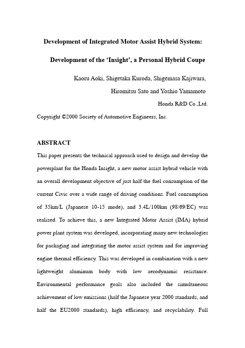
Development of Integrated Motor Assist Hybrid System:Development of the ‘Insight’, a Personal Hybrid Coupe Kaoru Aoki, Shigetaka Kuroda, Shigemasa Kajiwara,Hiromitsu Sato and Yoshio YamamotoHonda R&D Co.,Ltd. Copyright ©2000 Society of Automotive Engineers, Inc.ABSTRACTThis paper presents the technical approach used to design and develop the powerplant for the Honda Insight, a new motor assist hybrid vehicle with an overall development objective of just half the fuel consumption of the current Civic over a wide range of driving conditions. Fuel consumption of 35km/L (Japanese 10-15 mode), and 3.4L/100km (98/69/EC) was realized. To achieve this, a new Integrated Motor Assist (IMA) hybrid power plant system was developed, incorporating many new technologies for packaging and integrating the motor assist system and for improving engine thermal efficiency. This was developed in combination with a new lightweight aluminum body with low aerodynamic resistance. Environmental performance goals also included the simultaneous achievement of low emissions (half the Japanese year 2000 standards, and half the EU2000 standards), high efficiency, and recyclability. Fullconsideration was also given to key consumer attributes, including crash safety performance, handling, and driving performance.1.INTRODUCTIONTo reduce the automobile’s impact on society and the environment requires that it be increasingly cleaner and more energy efficient. The issues of energy conservation, ambient air quality, and reduction in CO2 emissions are increasing raised as global environmental concerns. One solution for dealing with these issues is the hybrid automobile. Honda has developed and introduced to several major markets worldwide the Insight, a new generation of vehicle design. The Insight combines a hybrid power train with advanced body technology features to meet an overall goal of achieving the highest fuel economy practical.The hybrid power train is a motor assist parallel configuration, termed IMA for ‘Integrated Motor Assist’. This power train combines a highly efficient electric motor with a new small displacement VTEC engine, a lightweight aluminum body, and improved aerodynamics to realize 3.4L/100km (CO2:80g/km) on 98/69/EC fuel economy. Low emissions performance was also targeted with emission levels achieving the EU2000.In addition to recapturing deceleration energy, the integrated motor provides high torque assist during typical urban driving accelerations. This allows a significant reduction in engine displacement and higherengine efficiency. Sustained hill climbing performance and high speed cruising capability are assured by a power-toweight ratio of approximately 56kW per metric ton. New engine technology includes the application of a new VTEC (Variable valve Timing and valve lift, Electronic Control) cylinder head design promoting high efficiency and fast catalyst activation, and a new lean NOx catalyst system which promotes lean burn combustion and a reduction in emissions. Extensive friction and weight reducing features are also applied.2.DEVELOPMENT TARGETS AND CONCEPTDevelopment was aimed at the achievement of extremely low fuel consumption. We set a target of twice the fuel economy of the current production Civic, Honda’s representative high fuel economy car at 7.0 L/100km (93/116/ EC). As a result, the Insight has the lowest fuel consumption in the world, among gasoline passenger cars.Exhaust emission performance often tends to be sacrificed for the sake of low fuel consumption. However, we also decided to match the low emissions performance achieved by other mass production cars. Consideration was also given to recyclability (another important environmental issue), crash safety performance, and the basic car characteristics including handling and styling.Summarizing the above, our development targets were as follows:The best fuel consumption performance in the world∙Ultra-low exhaust emissions∙Superior recyclability∙The world's highest level of crash safety performance∙Advanced styling∙Practical features and responsive handling∙Comfortable two-seat configuration with personal utility space3.POLICIES FOR FUEL CONSUMPTION REDUCTIONIn order to establish the technical approach for achieving the fuel consumption target, we conducted a detailed analysis of the energy consumption of the base car, a Civic equipped with a 1.5 liter engine. We found that it was useful to divide the targeted efficiency gains roughly into thirds, as shown in Fig. 1, in order to achieve the low fuel consumption and numerous other above-mentioned goals. These divisions are as follows.∙Improvement of the heat efficiency of the engine itself∙Recovery of braking energy and employment of idle stop using a hybrid power plant∙Car body technologies including reduction of weight and reduced aerodynamic and rolling resistance.Figure 1. Target of double the fuel economy of CIVICAiming to establish a benchmark for 21st century automobile power trains, we developed this new Integrated Motor Assist power train. This power train simultaneously achieves both extremely low fuel consumption of 3.4L/100km, and low exhaust gas emission performance, befitting a next-generation car.This paper reports on the newly developed IMA system, including the lean burn engine, electric motor, power control unit, battery technology, and exhaust emission control technology used in the "Honda Insight". 4.AIM OF THE IMA SYSTEMWhile developing this next-generation IMA hybrid system, we incorporated as many currently achievable technologies and techniques as possible, in order to achieve the "world's lowest fuel consumption".The following four system development themes were established in order to meet this target.1.Recovery of deceleration energy2.Improvement of the efficiency of the enginee of idle stop system4.Reduction of power train size and weight5.OVERVIEW OF THE IMA SYSTEM5.1. SYSTEM CONFIGURATION –As shown in Fig. 2, the IMA system uses the engine as the main power source and an electric motor as an auxiliary power source when accelerating. Using a motor as an auxiliary power source simplifies the overall system and makes it possible to use a compact and lightweight motor, battery, and power control unit (PCU).Figure 2. IMA SystemA permanent magnet DC brushless motor is located between the engine and the transmission. When decelerating, the rate of deceleration is calculated for each gear and the PCU controls the motor to generate electricity (recover energy), which charges a nickel-metal hydride battery. When accelerating, the amount of auxiliary power provided (hereaftercalled "assist") is calculated from the throttle opening, engine parameters, and battery state of charge. The PCU controls the amount of current flowing from the battery to the drive motor5.2.RECOVERY OF DECELERATION ENERGY –Recoveringdeceleration energy through regeneration makes it possible tosupplement the engine’s output during acceleration and reduce theamount of fuel consumed. Reducing resistance due to runninglosses, including engine frictional losses, increases the availableenergy for regeneration. In particular, minimizing the enginedisplacement is an effective means of reducing friction. Enginedisplacement reduction also has several other benefits, such asweight reduction and increased thermal efficiency. The IMAsystem effectively increases the amount of regeneration duringdeceleration by optimizing the engine and transmissionspecifications.5.3.REDUCTION OF ENGINE DISPLACEMENT –Reducingengine displacement is a very important factor in improving fueleconomy of a hybrid drive train. However, modern automobileshave to perform over a wide dynamic range. Reducing thedisplacement is equivalent to lowering the basic performancecharacteristics of the car. As shown in the output characteristicsgraph in Fig. 3, the IMA system assists the engine in the low rpmrange by utilizing the hightorque performance characteristic of electric motors. The motor can increase overall toruque by over 50% in the lower rpm range used in normal driving. Output in the high rpm range is increased by using a Variable valve Timing and valve lift Electronic Control (VTEC) engine. Thus sufficient peak power is assured and makes it possible to use a new, small displacement 1.0 liter engine.Figure 3.Engine speed (rpm) Output performance of IMA SYSTEM Assist from the electric motor while accelerating is a very efficient means of reducing the amount of fuel consumed.5.4.ACHIEVING LEAN BURN ENGINE OPERATION –Assistfrom the electric motor, based upon the throttle opening, creates quite linear torque characteristics. This, in turn, improves driveability. In addition, motor assist is also provided undermoderate load conditions to broaden the lean-burn operating range, bringing out the full potential of the newly developed lean burn engine.5.5.IDLE STOP SYSTEM – Stopping the engine rather than idling atstops is also an effective means for reducing fuel consumption. In order to restart the engine with the minimum amount of fuel consumption, the engine is quickly cranked to 600 rpm or more by the hightorque integrated motor before ignition occurs, as shown in Fig. 4. This makes it possible to minimize the amount of fuel consumed, in addition to the fuel saved by not running the engine at idle.There are many issues to be considered when performing idle stop. These include judging the driver's intent to stop, preparing for the restart, providing a smooth feeling of deceleration, and minimizing vibration of the car body when the engine stops.Figure 4.Time (sec) The number of cranking in the engine startThis IMA system results in the achievement of both very quick restarts and exceptionally smooth starts.6.MOTOR ASSIST MECHANISM6.1. DEVELOPMENT OBJECTIVES –By limiting the IMA motor functions to assistance and regeneration, development themes were established to achieve the following two points.1.A simple and compact structure2.A system weight of 10% (80 kg) or less of the completed car weight 6.2. THIN PROFILE DC BRUSHLESS MOTOR – A thin and compact DC brushless motor with engine assist and energy regeneration functions was coupled to the engine crank-shaft (Fig. 5).Figure 5. Section view of MotorThis is a high efficiency, compact, and lightweight permanent magnet-type three-phase synchronous electric motor with a maximum output of 10 kW. In addition to developing technologies to reduce the weight and increase efficiency, we also aimed to make the motor as thinas possible in order to achieve a compact power train. Lost wax precision casting process was used for the rotor, rotating by bending coupled to the crankshaft. This achieves high strength and lighter weight (approximately -20%) compared with normal cast products. For the rotor magnets, further improvements were made to the neodymium-sintered magnets used in the HONDA EV PLUS, realizing approximately 8% greater torque density and improved heat resistance. This design also results in a motor structure that does not require a cooling system. A split stator structure with salient pole centralized windings was developed and used to reduce the motor axial width. A split stator was adopted to drive the rotor. This makes it possible to use the salient pole centralized windings, which are both more compact and efficient than the conventional coil wave winding method, as shown in Fig. 6. In addition, centralized distribution bus rings (Fig. 7) formed from copper sheets were used for the harness that supplies electricity to the coils on both sides of the stator. This results in an extremely compact and simple structure. These improvements achieve an extremely thin motor with a width of only 60 mm. This represents a 40% reduction in width compared to conventional technology.Wave winding Salient pole windingFigure 6. Compare of windingFigure 7. Cut view of Motor6.3. NICKEL-METAL HYDRIDE (NI-MH) BATTERY – A nickel-metal hydride battery is used to store and provide electrical energy for the motor assist. This is an advanced battery which has already achieved proven results in the high specific energy version used for the HONDA EV PLUS electric vehicle. The hybrid vehicle battery features stable output characteristics, regardless of the state-of-chargestatus. It is also extremely durable in this application. The battery pack has an integrated structure consisting of 20 modules, each having sixD-size cells connected in series, arranged in a lattice formation. These 120 1.2 V cells are all connected in series for a total battery pack voltage of 144 V.6.4. POWER CONTROL UNIT (PCU) –The PCU performs precise control of motor assist/regeneration and supplies power to the 12 V power source. It has built-in cooling functions, which give it a lightweight, efficient and compact structure. Significant weight reduction was achieved by integrating an air cooling system using highly efficient cooling fins and a magnesium heat sink case.The inverter for the drive motor, which is the most important component within the PCU, has switching elements integrated into a single module for generating the three-phase AC current. These were separate components on the EV PLUS. The drive circuit has been miniaturized and converted to an IC using high density integration. These improvements have resulted not only in significant weight reduction, but have also improved the power conversion efficiency. Further, using phase control to drive the motor at very high efficiencies reduces the amount of heat produced and makes it possible to use a lightweight and simple air-cooling system. (Fig. 8)Figure 8.Inverter Cut view of PCU Heat Sink case7.ENGINE7.1. DEVELOPMENT OBJECTIVES – The following four points were set as development themes in order to achieve low fuel consumption over a wide range of operating conditions.1.Improvement of thermal efficiency2.Reduction of mechanical losses (-10% compared with conventionaldesigns )3.Reduction of size and weight (lightest weight in its class)4. Achievement of half the EU2000 standards7.2.ENGINE OVERVIEW AND SPECIFICATIONS –The enginespecifications are shown in Table 1 and the main new features and their purposes are shown in Table 2.First, a displacement of approximately 1000 cm3 was considered optimal for this vehicle with the IMA system, so a 3-cylinder engine was selected to minimize combustion chamber surface-to-volume ratio andmechanical losses. (Fig. 9)7.3.FUEL CONSUMPTION – Engine displacement could be reduceconsiderably in the motor assist powertrain because of the motor assist enhancement of low rpm torque, and also VTEC for sufficient peak power output from the engine. A key feature of this engine is the significant improvement in combustion efficiency through lean burn technology. Technologies adopted to make this possible include new intake swirl ports, which enhance the swirl (mixture formation) inside the cylinders. A compact combustion chamber and a high compression ratio also help by improving the indicated heat efficiency. This result in significantly shorter combustion times compared to conventional lean burn engines, allowing combustion in a leaner range with a higher air-fuel ratio. This significantly improves the fuel consumption.The new high swirl ports and compact combustion chamber are evolutions based on conventional VTEC lean burn technology. In the conventional VTEC engine, swirl is produced by keeping one intake valve closed in low speed operating conditions. However, in this engine the intake valves and intake ports are arranged more vertically to produce strong eddies in the mixture flowing into the cylinders.The conventional VTEC configuration has the inlet and exhaust rocker arms each supported by a separate rocker shaft. The new VTEC mechanism shown in Fig.10 combines these into a single rocker shaft, thus realizing a significant reduction in size. In addition, it narrows the valve included angle from 46° to 30°, allowing a high swirl port shape and a very compact combustion chamber.Figure 9. Cutaway view of engineFigure 10. Section view of cylinder7.4.REDUCTION OF MECHANICAL LOSS –In addition toimprovement of the indicated heat efficiency, reduction of mechanical loss is also important to improve fuel economy. To achieve this, the following the low friction technologies were used.∙Roller coaxial VTEC mechanism∙Piston micro-dimple treatment∙Offset cylinder structure∙Low tension piston rings∙Carburized connecting rodsThe roller coaxial VTEC structure (Fig. 11) is an adaptation of technology used in the Honda S2000 (high output sportscar engine) to a single-cam VTEC mechanism. The camshaft drive loss was reduced by 70% using a needle roller bearing in the area where the rocker arm slides on the camshaft. In addition, simultaneous reduction in both weight and size were achieved by incorporating the VTEC switching piston into the roller bearing inner shaft.Piston micro-dimple treatment consists of treating the surface of the piston skirt to create a micro-dimple surface. This increases the oil film retention performance and can reduce friction by approximately 30% when lowfriction oil is used.Figure 11. Section view of Roller VTECThese effects resulted in the development of a 0W-20 grade low viscosity oil that complies with ILSAC standards. The friction reducing effects of super-low viscosity oil were measured by engine motoring. These measurement results are shown in Fig. 12. In the current technology engine, the HTHS viscosity at the limit friction value was approximately 2.5 mPas. Being used together with the advanced low friction engine, the limit value was lower than the current technology engineThese low friction technologies have vastly reduced the overall engine friction, as shown in Fig. 13. In total, they have realized a reduction in friction of 10% or more compared to a conventional 1.0 liter engine design .Figure 12. Limit in friction reductionFigure 13. Engine friction7.5.WEIGHT REDUCTION – The structure and materials of almostall parts in this engine have been reviewed with the aim of creating the lightest engine in the world in the 1.0 liter class. This weight reduction extends even to the "skeleton structure technology" and "materials technology" fields carburized connecting rods as used on the S2000 (high output sportscar engine). Carburization strength enhancement technology contributes greatly to increasing engine operational speed. We applied this strength enhancement technology to create a slim connecting rod design for the IMA engine. This resulted in a weight reduction of approximately 30% compared to conventional connecting rods.Most oil pans are made of steel plate or aluminum alloy. Conventionalmagnesium materials have had problems withstanding the high temperatures of engine oil. In contrast to conventional materials, which experience a significant drop in creep strength at 120°C or higher, we have developed a new magnesium oil pan (Fig. 14) which ensures sufficient creep strength up to 150°C.Figure 14. Magnesium Oil PanThis oil pan is fastened using steel bolts with aluminum washers to prevent galvanic corrosion. The oil pan weight is 35% lighter than an aluminum oil pan, for a reduction in weight that is comparable to the ratio between the specific masses of the two metals.In order to expand the application of plastic parts, plastic materials were adopted for the intake manifold, cylinder head cover, water pump pulley, and intake system parts. These changes brought the discrete dry weight of the engine to less than 60 kg, which is the lightest weight in the world for the 1.0 liter class.7.6.EXHAUST EMISSION PERFORMANCE –Technology forsimultaneously achieving both lean burn and low exhaust emissions was adopted in this engine, achieving a notable reduction in NOx emissions.Combustion was improved by putting the exhaust system to the rear of the engine (Fig. 15). In addition, the exhaust manifold was integrated with the cylinder head and a NOx adsorption catalyst which reduces NOx emissions during lean burn operation was also newly developed.Figure 15. Section view of emission system7.6.1. Integrated Exhaust Manifold and Cylinder Head – Conventional cylinder heads have independent exhaust ports for each cylinder and a separate exhaust manifold acts to converge these exhaust ports into a single port is then mounted to the head. However, the new head on the Insight has a structure which converges the exhaust ports into a single port inside the head, as shown in Fig. 16. This greatly reduces the weight. In addition, the small heat radiating surface area reduces the exhaust gas heat loss, thus enabling early catalyst activation.Figure 16. View of Head7.6.2. Lean NOx Catalyst – The catalyst system on the Insight combinesa conventional three-way catalyst with NOx adsorbing materials. The NOx conversion mechanism of the newly developed catalyst is shown in Fig. 17. The NOx in the exhaust gas is adsorbed and separated by the NOx adsorption action of the catalyst during lean engine operating conditions. Conventional three-way catalyst operation reduces part of the NOx to nitrogen and oxidizes most of the HC and CO to CO2 and H2O during lean operation. However, since the exhaust gas contains large amounts of oxygen, there is relatively little NOx reduction with the three-way catalyst and most of the NOx is stored on the surface of the adsorbing material. When the exhaust is held at the theoretical air fuel ratio (stoichiometry) or richer air-fuel ratio, the adsorbed NOx is reduced to nitrogen using HC and CO as reducing agents. The adsorbent is regenerated at the same time. Thus, NOx, HC and CO are effectively converted using the three-way catalytic action of the catalyst combined with the NOx adsorber.This type of catalyst exhibits superior conversion performance during both lean operation and stoichiometric operation by switching betweenlean and stoichiometry operating conditions. It is essential to create a regenerative atmosphere before the NOx adsorption capacity becomes overloaded. This catalyst directly adsorbs NOx during lean burn engine operation and the adsorbed NOx is then reduced and exhausted as harmless nitrogen (N2) during stoichiometric operation.Figure 17. Exhaust gas purification mechanismThis catalyst is characterized by the direct adsorption of NOx to the catalyst surface during lean operation. Adsorption on the catalyst surface, instead of absorption as a compound inside the surface, facilitates conversion during reduction and also provides superior durability at high temperatures. This adsorptive type catalyst reduces NOx emissions during lean burn operation to 1/10 the level of the conventional three-way catalyst. It should be noted that the adsorption and conversion performance of this type of catalyst is sensitive to sulfur levels in the fuel, as sulfur can compete for the active NOx adsorbing sites. As a conventional three-way catalyst has virtually no NOx reduction during lean-operation, the lean burn operating range typically has to be reducedto keep NOx emissions down. Use of an adsorptive type catalyst maintains the full lean burn range and improves fuel economy, even while reducing NOx.This vehicle can also satisfy the EU2000 standards, making this a highly efficient lean burn engine that complies with exhaust emissions standards throughout the world.8.CONCLUSIONThis paper presents a general overview of the recently developed motor assist hybrid powertrain, as well as a description of its various components and its output and emission performance. This hybrid power train simultaneously achieves ultra low fuel consumption and low exhaust emissions. It also achieves a compact, lightweight power train layout. We believe this system advances 21st century automotive technology toward regional and global environmental goals. REFERENCES1.Aoki, Kaoru, et al.: "Development an Integrated Motor Assist HybridSystem", JSAE No. 98-99 1612.Yamaguchi, Tetsuro: "CVT Control in the HONDA Hybrid 'IMA'",No. 9908 JSAE SYMPOSIUM, Latest Motive Power Transmission Technologies '99, p.37403.Ohno, Hiroshi, et al.: "Development of a NOx Adsorptive ReactionType Three-Way Catalyst", HONDA R&D Technical Review, V ol. 11No. 2 (October 1999), p.45-504.Fukuo, Koichi, et al.: "Development of the Ultra Low FuelConsumption Hybrid Car 'Insight'", HONDA R&D Technical Review, V ol. 11 No. 2 (October 1999), p.1-85.Hideki Tanaka, et al .: "The Effect of 0W-20 Low Viscosity EngineOil on Fuel Economy”, SAE Paper No.1999-01-3468,Fuels and Lubricants meeting and Exposition, Toronto, Ontario, Canada, October 1999.6.Aoki, Kaoru, et al.: "An Integrated Motor Assist Hybrid System",SAE Paper No.2000-01-2059, Government / Industry Meeting, Washington, D.C., USA。
- 1、下载文档前请自行甄别文档内容的完整性,平台不提供额外的编辑、内容补充、找答案等附加服务。
- 2、"仅部分预览"的文档,不可在线预览部分如存在完整性等问题,可反馈申请退款(可完整预览的文档不适用该条件!)。
- 3、如文档侵犯您的权益,请联系客服反馈,我们会尽快为您处理(人工客服工作时间:9:00-18:30)。
With the rapid development of automobile industry, there is comfort and vehicle vibration and noise control of more and more stringent requirements. According to relevant data shows that 70 percent of the city noise from the traffic noise, and traffic noise is mainly car noise. It is seriously polluting the urban environment, affecting people's life, work and health. So noise control is not only related to comfort, but also related to environmental protection. However, all also from the vibration noise, vibration can cause certain parts of the early fatigue damage, thereby reducing the service life of motor vehicles; excessive noise can damage hearing the driver will enable the rapid driver fatigue, thus driving security constitutes a grave threat. So noise control, is also related to motor vehicle durability and safety. Thus vibration, noise and comfort are the three closely related, it is necessary to reduce vibration, reduce noise, but also improve ride comfort, and ensure the product economy, vehicle noise control in the standard range.One type of noise arising from car noise are the main factors of air power, mechanical drive, the electromagnetic three parts. From the structure can be divided into the engine (ie, combustion noise), the chassis noise (ie, power train noise, all components connected with the noise), electrical equipment, noise (cooling fan noise, car noise generator), body noise (such as body structure, shape and attachment installation unreasonable noise). One of the engine noise accounted for more than half of motorvehicle noise, including noise and body intake noise (such as engine vibration, the rotational axis Valve, Jin, door switches, such as exhaust noise). Therefore the engine vibration, noise reduction has become a key automotive noise control.In addition, automobile tires at high speed, it will also cause more noise. This is because of the tire at the ground flows, the pattern is located in the air by ground tank and re-extrusion process caused by inhaling gas pump sound, as well as tread patterns with percussive sound of the road.2 noise requirements of regulations in Europe, from October 1996 onwards, the external bus 77dBA noise must be reduced to 74dBA, noise was reduced by half energy, the end of the century further reduced to 71dBA. Japan's laws and regulations, small car in the next decade to control noise standards at the following 76dBA. A number of domestic cities are also planning to traffic trunk lines in 2010 to control noise at the average of less than 70dBA. According to the domestic current data indicate that the domestic value of bus noise permit shall not exceed 82dBA, light trucks for 83.5dBA. This shows that our country in the vehicle noise control will have to make do.3 noise assessment noise evaluation mainly refers to the car, outside noise and vibration adaptive value. Evaluation methods can be divided intosubjective evaluation and objective evaluation. Subjective assessment of the impact of vehicle noise is a major factor in comfort, loudness and uncertainties, such as semantic differential method can be used for subjective evaluation. At an objective evaluation, can be used PCNM noise measuring device for measuring test analysis; addition simulation technology in the finite element method (FEM) and boundary element method (BEM) has been widely applied.4 noise control noise generation and dissemination in accordance with the mechanism of noise control technology can be put into the following three categories: First, the control of noise sources, are two routes of transmission of noise control, noise three recipients are protected. One of the control of noise sources are the most fundamental, the most direct measures, including noise reduction to reduce the exciting force and the engine parts of the exciting force response, which means transformation of acoustic source local oscillator. However, it is difficult to control noise sources when necessary in the route of transmission of noise to take measures, such as sound absorption, sound insulation, noise reduction, vibration and vibration isolation measures. Motor vehicles and vehicle vibration and noise reduction level of power, economy, reliability and strength, stiffness, quality, manufacturing costs and use are closely related.4.1 engine to reduce vibration and noise of the engine noise is the focus of automotive noise control. Engine vibration and noise are generated at source. Engine noise is from fuel combustion, valve bodies, gears and piston timing noise percussion synthesis.(1) ontology engine noiseLower engine noise will be ontological transformation of local oscillator sound sources, including methods such as finite element method analysis and design engines, selection of soft combustion process, improve the structure of the body stiffness, with the use of tight space, reduce noise cylinder cover. For example in the oil pan on an additional stiffener and diaphragm to improve the stiffness of oil pan to reduce vibration and noise. In addition, give the engine Tu damping material is an effective approach. Damping materials can kinetic energy into thermal energy. To deal with the principle of damping is a damping materials and components into its vibrational energy to consume. It has the following structure: Freedom damping layer structure, and spacing of freely damping layer structure, and constrained damping layer structure and spacing of constrained damping layer. It is clear that the adoption of a decrease of resonance amplitude and accelerated the decay of free vibration, reducing the various parts of the Chuan-Zhen capacity, an increase of parts at or above the critical frequency of vibration isolationcapacity.At present, some countries have designed an engine experts active vibration isolation system to reduce engine vibration, in order to achieve the purpose of noise reduction.(2) intake noiseEngine intake noise is one of the main noise source, the Department of the engine noise of air power, with the engine speed increases to strengthen. Non-supercharged engine intake noise major components, including the cyclical pressure fluctuation noise, vortex noise, the cylinder of the Helmholtz resonance noise. Diesel engine supercharger intake noise mainly from the turbocharger compressor. Two stroke engine noise from the Roots pump. In this regard, the most effective method is the use of intake muffler. There is a resistive type muffler (absorption type), resistant muffler (expansion type, resonance type, interference-type and porous decentralized) and the composite muffler. To combine with the air filter (that is in the air filter on an additional resonance chamber and sound-absorbing material, for example, type R3238) has become the most effective intake muffler, muffler volume of more than 20dBA.4.2 Chassis Noise(1) Department of exhaust noiseDepartment of the chassis exhaust noise is the main noise sources, mainly from the exhaust pressure pulsation noise, air flow through the valve seat when issued by eddy current noise, because of boundary layer airflow disturbance caused by noise and exhaust Office jet noise composition. Designed to optimize the performance of a good muffler, to reduce car noise are one of the important means. Optimize design method has acoustic finite element method and acoustic boundary element method, but is still in its infancy. Muffler to avoid the transmission characteristics and vibration characteristics of coupled mufflers are designed to be focused on solving a problem. Secondly, to reduce exhaust noise and improve power is also a pair of contradictions, because to reduce exhaust noise and lower exhaust back pressure on the design of the exhaust pipe has a diameter of conflicting demands, the former requires a smaller diameter, which is opposite . In this regard, the use of parallel flow path of the dual function muffler, at reduced air pressure and reduce noise to be effective. In addition, the engine exhaust manifold to the muffler inlet pipe section, the use of flexible pipe vibration, noise reduction effect can be reduced to about 7dBA.(2) power train noisePowertrain noise from the vibration caused by变速齿轮meshing and rotating shaft vibration. General measures taken are: First, choose low-noise transmission, engine and gearbox are two and the main reducer,such as rear axle and chassis components for flexible rubber pad connections, so as to achieve the purpose of isolation; are three-axis rotational control balance degrees, to reduce torsional vibration.4.3 Electric equipment noise(1) cooling fan noiseCooling fan noise happened devices are subject to wind retaining ring, water pump, radiator and transmission, but the noise generated depends primarily on the chassis.(2) automobile generator noiseAutomotive generator noise depends on the effects of a variety of sources, these sources have magnet source, mechanical and air power source. Noise level depends on the generator magnetic structure and ventilation systems, as well as generators precision manufacturing and assembly.4.4 Body NoiseAs the speed increased, the body will be more and more noise, and air power are the main causes of noise. Therefore, the following programs to improve the body noise: First, to streamline the design of the body, achieve a smooth transition; two are in between the body and framecomponents to adopt a flexible connection; three interior is softened, such as Inner Mongolia at the roof and body skin the use of sound-absorbing material.In addition, the car at high speed when the tire is also a source of noise. Real vehicle Inerting line method has been measured: Tire Tread greater, then the greater the noise. In addition, the tire tread with the noise generated also have a great relationship, there is a reasonable choice of the pattern of steel cord for radial tires to reduce tire noise are an effective way. Materials for the tire, the use of more flexible and soft rubber with high, you can create a low-noise tires.4.5 Other measuresAutomobile noise control, except in the design on the use of optimization methods and optimization of selected components, it can also carry out active control of noise. This is based on sound muffler technology, the principle is: the use of electronic muffler system with the opposite phase of the acoustic noise, vibration so that the two cancel each other out in order to reduce the noise. This muffler device used extremely advanced electronic components, has excellent noise reduction effect can be used to reduce vehicle noise, engine noise, the engine could also be used to proactively support systems, to offset the engine vibration and noise中文翻译:与汽车工业的迅速发展,有舒适和车辆振动和噪声控制的越来越苛刻的要求。