
卡乐电极加湿器UEY系列说明书
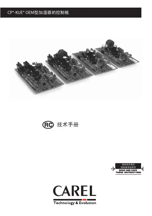
8. 报警
20
9. 维护和部件
22
9.1 型号UE001 - UE018的加湿器部件..................... 22 9.2 型号UE025 - UE065的加湿器部件.................... 24 9.3 清洁和维护加湿桶............................... 26 9.4 机械地排出加湿桶内的水......................... 26 9.5 加湿桶连接,三相型UE025 - UE065..................................................26 9.6 清洁和维护其它部件............................. 27
3
“UE BASIC” +03C0042EZ - rel. 1.1 - 09.07.2010
CN
目录
1. 产品简介和组装
7
1.1 humiSteam (UEY*).............................................................................................. 7 1.2 尺寸和重量...................................... 7 1.3 打开包装 ....................................... 7 1.4 定位............................................ 7 1.5 墙面安装........................................ 7 1.6 拆下前盖板...................................... 8 1.7 固定前盖板...................................... 9
1、电击危险 加湿器包含了带电的电子部件。在打开内部结构或维护和安装前请先 断开电源。 2、漏水危险 加湿器自动地和持续的灌入/排出一定数量的水。连接的故障或加湿器 故障都可能导致漏水。 3、燃烧危险 加湿器包含了高温部件,并且传送100°C/212°F的蒸汽。
CN
其是否由于疏忽引起的),或对于由于安装、使用或无法使用产品引 起的任何其他责任,CAREL及其雇员或其子公司概不承担责任,即使 CAREL或其子公司已被告知存在此等损害之可能。
6. 启动和用户界面
17
6.1 开启........................................... 17 6.2 停机........................................... 17 6.3 显示屏......................................... 17 6.4 按键 ....................................................................................................................17 6.5 主界面 ..............................................................................................................17 6.6 禁用........................................... 18 6.7 恢复工厂默认设置............................... 18 6.8 软件版本显示................................... 18 6.9 开关量对应(主板软件与连接端的对应)........... 18 6.10 复位小时和比率计时器.......................... 18 6.11 参数:保存/恢复用户设置....................... 18 6.9 手动排出加湿桶内的水........................... 18
废弃物处理
CAREL加湿器是由金属部件和塑料部件组成。参照2003年1月27日发布 的欧盟指令2002/96/EC和有关国家的法律进行处理,并请注意: 1.WEEE不能作为市政废物处理,必须收集并分开处理。 2.必须使用当地法律规定的公共或私人废物收集系统。此外,在购买
新设备时,可以将使用寿命已尽的旧设备送还销售商。 3.本设备可能含有有害物质:使用或者处理不当可能会给人身健康和
环境造成不利影响。 4.设备本身、包装物或者操作手册上的符号(划叉的轮式垃圾箱)表
示设备已于2005年8月13日后投放市场,必须单独处理。 5.非法处理电气和电子废弃物的行为将按当地废弃物处理法规进行处
罚。
材料质保:2年(自生产日期开始,不包括损耗部件)。
认证: CAREL已通过 ISO 9001设计和生产系统认证,产品的质量和安全 都有保障,带有 标记。
5. 远................................... 16 5.2 RS485监控网络 (M1.1-M1.3)...................................................................... 16
CAREL奉行持续发展的方针,因此,对于本文档中所描述的任何产 品,CAREL均保留不经事先通知而进行改良和改进的权利。本手册所列 的技术规范可能会在不事先告知用户的情况下发生改变。 CAREL的通用合同条款(见网站)和/或其与客户签订的 具体协议已对CAREL就其产品应负的责任作出具体规定。具体而言, 在可采用的法规所适用的区域,对于任何损失的赢利或销售额、数据 或资料丢失、重置商品或服务成本、物或人的损害、停工时间或任何 类型的直接的、间接的、附带的、实际的、惩罚性的、惩戒性的、特 别的或后果性的损害(无论其是属于合同之内或合同之外的、也无论
11. 总体特点和型号
31
11.1 humiSteam型号和电气规格 ....................... 31 11.2 技术规格...................................... 32 11.3 蒸汽软管类型.................................. 32 11.4 集中喷气式蒸汽分配器型号...................... 33 11.5 线性分配器型号和典型安装...................... 33 11.6 参数表b1........................................................................................................35 11.7 通过网络控制主板..........................................................................39 11.8 用变量I62和I63控制蒸汽生产...................... 40 11.9 通过网络读取报警纪录.......................... 40 11.10 网络通讯失败.................................. 40 11.11 UEY控制板上的Modbus®协议..................... 40 11.12 例外管理...................................... 40
重要提示:
• 本产品的安装必须做接地处理,在加湿器上使用专用的黄色-绿色接 线端。
• 产品使用环境和电源条件必须遵照产品标签上描述的条件。 • 本产品是专门为直接或通过分配系统(风道)加湿室内而设计的。 • 设备操作必须是由熟悉产品必要的预防措施的,并且能完成正确安
装、运行或对产品进行技术服务的有资质的人员进行。 • 蒸汽生产只能使用具备本手册中指示的特征的水。 • 所有的工作都必须按照手册中和产品标签上指示的规范进行。任何
1.8 配件和附件...................................... 9
2. 水路连接
10
2.1 供水........................................... 11 2.2 排水........................................... 11
humiSteam
加湿器/humidifiers
用户手册 User manual
重要提示
CAREL加湿器是具有先进技术的产品,随产品一同提供的技术资料中有 详细的操作说明,用户也可从网站下载说明(购买产品 前也可下载)。 CAREL的每一款产品均涉及先进技术,所以均需要设置/配置/编程/调 试,以使其能以最佳方式运转,满足特定应用需求,若不能按照用户 手册的要求/说明完成上述各项操作,可能会导致最终产品出现故障。 这种情况下,CAREL不承担任何责任。 为了使特定的装置和/或设备最终能达到预期的效果,用户(设备最 终的制造商、开发商或安装人)要承担与产品配置相关的所有风险和 责任。CAREL会根据特定的协议,以顾问身份参与最终设备/应用的调 试,但在任何情况下,均不承担最终设备/系统正确运转的责任。 此外,除上述提到的敬告和建议外,还应注意以下事项以正确的使用 产品:
10. 电路图
28
10.1 UE001 - UE009单相加湿器电路图.................... 28 10.2 UE003 - UE018 三相加湿器电路图................... 29 10.3 UE025 - UE065 三相加湿器电路图................... 30
4. 电气连接
卡乐加湿器说明书

用户手册.我们希望能够节省您的时间与金钱!我们向您郑重承诺:通过阅读此手册,能够获得有关仪器正确的安装途径以及安全的使用方法。
注 意此类型加湿器是通过在盛水的容器(加湿罐)中插入电极,当电极通电后产生热量加热水,随之生成蒸汽;使用特殊的蒸汽分配系统可以用来为环境或工业过程加湿。
在蒸发过程中水质是非常重要的,同时考虑到对容器的维护,要求供水是不经过任何处理的水,只要是可饮用并含有矿物制的水即可(看3.1章);通过供水电磁阀将水源源不断送入加湿罐中。
装置独特的设计在于使用蒸汽分配系统,可以直接为房间或管道加湿。
装置的安装和维护需要专业人员,严格按照说明书中所介绍的相关内容操作,并注意装置外部与内部的铭牌上的标注。
实际环境以及电源供电电压必须与指定的值相同。
厂商没有允许的有关装置的其他应用与调整是不正确的。
由于不正确的操作造成对仪器或其他方面的损害责任后果由用户承担。
请注意装置内有许多电气元件,并且装置表面的温度较高。
装置的维护与维修需要由专业人员来完成。
在查看内部元件之前必须断开电源。
装置的安装必须符合当地的标准。
在任何情况中都需要遵守当地的安全标准。
加湿器组件的处理加湿器是由金属与塑料制品组成。
对组件的处理必须遵守当地的垃圾标准。
保修:2年(从产品出厂起,除了损耗件如加湿罐)CE的标志确保了产品的品质以及安全性。
请在安装机器之前,仔细阅读说明书中安全操作的事项,并注意装置上的有关说明。
目录:1. 介绍机型与组件 (5)1.1 机型 (5)1.2 介绍组件 (6)2. 安装 (8)2.1 储存 (8)2.2 布局 (8)2.3 固定 (8)2.4 拆除并重新安装前端盖 (9)3. 水路连接 (10)3.1 水质特性 (10)3.2 排水特性 (11)3.3 管路连接 (11)3.4 水路连接图 (12)3.5 检查 (12)4. 蒸汽的分配 (13)4.1 蒸汽直接分配方式:送风式蒸汽分配器 (13)4.2 冷藏间内的蒸汽分配 (13)4.3 风道里的蒸汽分配器--直线型与集中式分配器(OEM) (13)4.4 集中喷射式蒸汽分配器 (14)4.5 风道内直线式分配器 (15)4.6 蒸汽分配管的连接 (15)4.7 安装冷凝液回流管 (16)4.8 检查 (16)5. 电气连接 (17)5.1 电源电压 (17)5.2 检查控制回路变压器电压值 (18)5.3 主控板 (19)5.3.1 P型 (19)5.3.2 H型 (19)5.4 外部控制信号 (20)5.4.1 P 型控制器:ON/OFF 操作 (20)5.4.2 P 型控制器:比例操作 (21)5.4.3 H 型控制器 (22)5.5 辅助触点 (23)5.5.1 报警触点 (23)5.5.2 除湿触点(H型控制器) (24)5.5.3 远程端子/监控(H型控制器) (24)5.5.4 使用不同的传感器(H型控制器) (24)5.6 检查 (24)5.7 带有P型控制器的1-5Kg/h的加湿器单相电路图 (25)5.8 带有H型控制器的1-5Kg/h的加湿器单相电路图 (26)5.9 带有P型控制器的3-15Kg/h的加湿器三相电路图 (27)5.10 带有H型控制器的3-15Kg/h的加湿器三相电路图 (28)5.11带有H型控制器的25-45Kg/h加湿器的三相电路图 (29)5.12 带有P型控制器的25-45Kg/h加湿器的三相电路图 (30)5.13 带有H型控制器的25-35Kg/h加湿器的三相w-k电路图 (31)5.14 带有P型控制器的25-35Kg/h加湿器的三相W-K电路图 (32)5.1525-45kg/h的三相蒸发器结构 (33)6. 启动,控制,关闭 (34)6.1 初步检查 (34)6.2 启动装置 (34)6.2.1 使用新的加湿罐 (34)6.2.2 使用空的加湿罐 (34)6.2.3 开始操作 (34)6.2.4 使用空的加湿罐 (34)6.3 加湿器控制器 (35)6.3.1 P 型控制器,LED指示,开关或比例操作 (35)6.3.2 H 型控制器,带有数字LED显示,湿度控制运行 (36)6.4 关闭 (37)7. H 型控制器的参数 (38)7.1 读取并设置环境湿度设定点 (38)7.2 读取并设定控制参数--读取测量值 (39)7.3 读取并设定配置参数 (40)7.4 参数调节的有效性 (42)7.5 恢复缺省值(工厂参数) (42)7.6 复位计时器 (42)7.7 显示调节测量参数的单位 (43)8. 远程遥控 (43)8.1 遥控器简介 (43)8.1.1 控制遥控器的按键 (43)8.1.2 调整主要参数的按键(直接访问键) (44)8.1.3 遥控器上的控制手操器键 (44)8.2 使用遥控器设定参数 (44)8.2.1 不需要键入访问参数(C2=0)的参数编辑 (44)8.2.2 需要键入访问参数(C2≠0)的参数编辑 (44)8.2.3 读取测量数据 (44)8.2.4 调节主要参数(使用特殊按键) (44)8.2.5 调节主要参数(不使用特殊按键) (45)8.3 退出编辑过程 (45)9. 维护与备用件 (45)9.1 更换加湿罐 (45)9.2 维护其他组件 (46)9.3 更换组件 (47)9.3.1 辅助回路中的线圈 (47)9.4 组件 (47)9.4.1 单相加湿器 (47)9.4.2 三相加湿器 (48)10. 报警,报警故障的检修 (49)10.1 P型控制器的报警 (49)10.2 H型控制器的报警 (49)10.3 报警以及信号表 (50)10.4 排除故障 (52)11. 工作原理,控制原理以及其他功能 (53)11.1 工作原理 (53)11.2 控制原理 (53)11.2.1 ON/OFF控制--P型控制器;A0=0 的H型控制器 (53)11.2.2 比例控制--P型控制器; A0=1 的H型控制器 (53)11.2.3 带有相对湿度传感器的自动控制-- A0=2的H型控制器 (53)11.2.4 带有环境湿度传感器与第二传感器的自动控制-- A0=3的H型控制器 (54)11.2.5 蒸汽浴的应用:带有温度传感器的自动控制-- A0=4的H型控制器 (54)11.3 设定报警门限值(H型控制器) (54)11.4 其他功能 (54)11.4.1 测量供水的电导率 (54)11.4.2 自动排水 (54)11.4.3 放泡沫操作 (55)11.4.4 除湿要求信号 (55)11.4.5 由于长时间的关闭自动排空加湿罐 (55)11.4.6 带电排水 (55)11.4.7 由于需求的大幅度减少而进行的排水 (55)11.4.8 关闭"加湿器加湿罐将耗干"与 "加湿罐耗干"报警 (55)12.技术指标 (56)12.1 尺寸与重量 (57)12.2 遥控的技术指标 (57)12.3 蒸汽的分配系统的技术指标 (57)1. 机型与组件的介绍1.1机型使用由10位字符组成的代码来区分不同的机型,每位字符具有以下含义:U E X X X X X000例如:UE010PL000 ,代表浸入式电极加湿器,且:· 每小时蒸汽产量为10 kg/h (010);· 比例-ON/OFF 控制 (P);· 400Vac, 三相电源供电(L)。
卡乐加湿器使用说明_CP
5,0 3,75 230 3 9,4
CP405K*
1
20
5,0 3,75 400 3 5,4
CP405L*
1
20
5,0 3,75 460 3 4,7
CP405M*
2
20
5,0 3,75 575 3 3,8
CP405N*
2
20
KUET2*
8,0 6,00 200 3 17,3
CP408J*
1
40
8,0 6,00 208 3 16,7
技术参数:
电源: 能耗:
24 Vac, -15%到+10 %, 50/60 Hz 9 VA (不包括电磁阀) - 35 VA max. (包括电磁阀)
开关量输出
电极电源 (CP1* 和CP2* ): 2个 SPST 继电器, 250Vac 20A 电阻(12A 感抗 cosψ=
(继电器: 微型中断类型: 0,4);触点切换次数最小值: 100,000
认), (2-10 V, 0-1 V 信号仅通过RS485选择)
运行条件: 储存条件: 环境污染等级:
还可选择使用VR-SET (参考上面 “开关输入”)。 0到60 °C; <90% RH 无凝露 -10到70 °C; <90% RH 无凝露 正常等级
TAM
CP1* 和 CP3* 外置 09C412A017 / CP2* 和 CP4* 内置
1
60
9,0 6,75 230 1 29,3
CP409D*
1
60
KUET3* 10,0 7,50 208 3 20,8
CP410W*
1
40
10,0 7,50 230 3 18,8
UEY加湿器安装与调试

UEH/UEP -vs.- New UEX/UEY
UEY加湿器 简介__新的起动运算法则
UE008HL 8 kg/h 400 VAC 3-phase with BL0T2B @ 130 µS/cm
UEX/UEY UEH/UEP
10
03:06:51 03:22:41
humiSteam…
UEY加湿器安装-水路安装
1. 2.
3. 4. 5. 6.
给供水上游安装一个手动截止阀(能够 切断供水) 将加湿器与供水连接。使用一根带 3/4”G接头的软管(随机附件,UE025及 以上含止回阀 ) 安装一个机械过滤器,阻止固体杂质进 入加湿器 连接一段隔热的导管或软管用于排水( 可抗温度100 °C),最小内径为40 mm 准备一个漏斗,中断排水管路中的连续 性 连接一个排水弯头以防止不好的气味回 流(最小内径为40 mm)
实际小时计数器 (h)
设定最大蒸汽生产量
Technology & Evolution
humiSteam…
电极式加湿器调试-恢复默认值(工厂设置)
恢复工厂默认设置 在主画面中,按下ENTER键, 直到显示密码画面: • 输入密码 • 显示dEF信息,闪烁 按下ENTER键,确认或按下 ESC退出。如果没有按键被按 下持续30键,显示屏将返回到 主画面。
控制器
操作界面(手操器)
Technology & Evolution
humiSteam…
UEY加湿器 –随机附件
Technology & Evolution
humiSteam…
UEY加湿器 –其它可选常见附件
Technology & Evolution
电极加湿器使用说明

电极加湿器工作原理:电极式蒸汽加湿是一种简便高效的加湿方法。
利用它金属电极插入有水的容器中,一般水中都含有导电介质,这时水就作为电阻,当电流流过水中时,导电介质不断的剧烈运动,从而产生热量(利用电阻的热效应),当水被加热至沸腾后就产生蒸汽,进行加湿。
加湿过程中,加湿控制模块时刻检测加湿电流的强度,再与目标加湿电流强度进行比较,从而控制进水阀和排水阀的动作,通过进排水阀的动作来控制加湿罐内水位的高低从而实现控制蒸汽的产量,达到自动精确控制加湿的目的。
电极加湿的控制方式分为开关式和比例式,比例调节控制能使加湿量无极连续产生,保证加湿的精确需求。
自动上水补水并自动调整合适的水位:开机自动上水,工作时自动补水并根据水质、水温及上、排水流量自动调整加湿罐内合适的工作水位。
i主水杯使用条件■驱:l-IOhar (0. 1-lMPs;■:酋迪自来水】■匸作斤力J{J bar■常岀lOOOPa■讣1見芯庶:1■啜护岳墟:IP43自动清洗:控制板根据水质和电流变化率自动调整清洗次数和清洗时间。
极限水位限制功能:因水质、电极水垢等原因使电流检测失效,加湿罐水位升高到极限值接触到极限水位电极,控制板自动强行关闭进水阀。
电极式加湿器的优点:加湿迅速、均匀、稳定、高精度、高效率、无水滴喷泻、无白粉、无任何杂质、完全杀死细菌,是世界公认的最为洁净卫生的加湿方式。
特别适合于对环境要求严格的生物、制药、食品等车间场所以及对舒适性要求比较高的环境。
加湿显示-工作指示电源开关面板图体积小巧紧凑,可按用户要求任意组合安装,确保系统部件的连接配套。
有开关型控制精度5%比例型可以实现比例控制,在最大加湿量的20-100%之间自动调整。
小电流、大电流及异常故障保护功能:①因水垢等原因在一定的时间内加湿电流达不到额定值;② 因水质及其它异常原因使电流超过极限值;③其他异常原因致使加湿控制板故障等;以上三种情况任意一种情况发生控制板都会自动停止工作。
卡乐电极加湿器UEY系列说明书

重要提示:
• 本产品的安装必须做接地处理,在加湿器上使用专用的黄色-绿色接 线端。
• 产品使用环境和电源条件必须遵照产品标签上描述的条件。 • 本产品是专门为直接或通过分配系统(风道)加湿室内而设计的。 • 设备操作必须是由熟悉产品必要的预防措施的,并且能完成正确安
装、运行或对产品进行技术服务的有资质的人员进行。 • 蒸汽生产只能使用具备本手册中指示的特征的水。 • 所有的工作都必须按照手册中和产品标签上指示的规范进行。任何
1、电击危险 加湿器包含了带电的电子部件。在打开内部结构或维护和安装前请先 断开电源。 2、漏水危险 加湿器自动地和持续的灌入/排出一定数量的水。连接的故障或加湿器 故障都可能导致漏水。 3、燃烧危险 加湿器包含了高温部件,并且传送100°C/212°F的蒸汽。
CN
其是否由于疏忽引起的),或对于由于安装、使用或无法使用产品引 起的任何其他责任,CAREL及其雇员或其子公司概不承担责任,即使 CAREL或其子公司已被告知存在此等损害之可能。
4. 电气连接
14
4.1 准备布线 ........................................................................................................ 14 4.2 电源线连接 ................................................................................................... 14 4.3 蒸汽生产控制信号 (M2.1 - M2.7) ........................................................ 14 4.4 报警触点 (M5.1 - M5.2).............................................................................. 16 4.5 辅助触点:生产请求,外置风扇控制 (M14.1 - M14.3).......... 16
卡乐加湿器使用说明_CP
卡乐加湿器使用说明_CP一、产品概述卡乐加湿器是一款专为家居环境设计的高效能加湿器,在开启加湿功能的同时,还具备空气净化功能。
产品采用纳米气雾技术,可以将水分分解成微小的雾霾颗粒,通过超声波震荡后,将雾霾颗粒均匀地释放到室内,提供湿润而清新的家居环境。
二、产品特点1.纳米气雾技术:采用高科技纳米气雾技术,将水分分解成微小的雾霾颗粒,提供更细腻的加湿效果。
2.超声波震荡:通过超声波震荡,将雾霾颗粒均匀地释放到室内,实现全方位加湿。
3.空气净化功能:产品配备了过滤网,能够有效过滤空气中的细菌、灰尘等有害物质,提供清新的室内空气。
4.大容量水箱:产品配备了大容量水箱,一次注水可以持续使用较长时间,免去频繁补水的烦恼。
5.双重安全保护:产品内置了水位监测装置和自动断电保护装置,能够及时检测和保护产品的使用安全。
三、使用方法1.准备工作(1)将产品放置在平稳的台面上,确保不会倾斜或者摇晃。
(2)打开产品包装,取出加湿器主机和配件。
(3)确保产品断电状态,并将电源线连接到加湿器主机和电源插座。
2.加水(1)按住产品底部的水箱把手,逆时针旋转,将水箱取出。
(2)将水箱底部的水阀打开,将清水或纯净水倒入水箱,注意水位不要超过最高水位线。
(3)将水箱放回加湿器主机,顺时针旋转,确保水箱与加湿器主机紧密连接。
3.运行开关(1)按下加湿器主机上方的电源开关,加湿器开始工作。
(2)按下加湿器主机上方的净化开关,启动空气净化功能。
4.设置加湿程度(1)加湿器主机上方的湿度调节旋钮可以设置加湿程度,旋钮逆时针调节可以增加加湿量,顺时针调节可以减少加湿量。
(2)可以根据实际需要适应湿度环境来进行调节,通常在25%到60%之间为室内舒适湿度。
5.使用注意事项(1)在加水过程中,切勿将水洒入加湿器主机或电源插座。
(2)不要将湿度调节旋钮调至最大,以免造成室内湿度过高。
(3)产品使用时,请确保加湿器主机周围没有易燃物品,并保持通风良好。
卡乐电极式加湿器使用手册for申菱5.31
卡乐电极式加湿器使用手册for 申菱5.31卡乐电极式加湿器使用手册目录一、我司所用到的卡乐加湿器型号及元件描述 11.订货号与产品型号对照表 (1)2.加湿桶型号表示方法 (2)3.加湿控制板(CP3、CP4)技术说明 (3)二、我司常规选用的加湿器外形及尺寸 (6)1.外形及产品结构描述 (6)2.各系列加湿器几何尺寸 (7)三、加湿器的安装 (9)1.安装步骤 (9)2.注意事项 (11)四、加湿器控制接线图(CP3、CP4) (13)五、加湿控制板跳线说明 (15)1.跳线D IP SWITCHES A(8位拨码开关) (15)2.跳线D IP SWITCHES B(8位拨码开关) (15)3.跳线D IPS“TA RATE”(4位拨码开关)及互感器绕线 (16)六、加湿器开机前的检查工作 (18)重要警告 (18)1.初检 (18)2.开机 (18)七、常见器故障及处理方法 (19)1.常见故障及解决方法: (19)2.关于控制板报警 (22)八、加湿器的维护 (28)1.更换加湿桶 (28)2.更换电极片 (28)3.定期检查 (29)4.其它装置的保养 (30)九、控制板程序下载软件:HUMISET 使用说明 (32)1.硬件连接 (32)2.软件安装 (33)3.软件使用 (33)一、我司所用到的卡乐加湿器型号及元件描述1.订货号与产品型号对照表表1.1: 订货号与产品型号对照表注:⑴以上型号的加湿器适用的加湿电压为3相380V,单相或三相220V加湿电压的加湿器需参考另外的资料选型。
⑵公司常规暂按低电导率订货号进行选型,如有变更将另行通知。
⑶订货号说明电导率类别:00—标准电导率,L0—低电导率,H0—高电导率加湿量:03—5~8kg,04—10~15kg,05—25~35kg,06—45kgB表示加湿桶公司代号:SL表示申菱公司出厂定义:HUM表示加湿器2.加湿桶型号表示方法例如:BLCT3B00W0表示加湿量为10~15KG 的可清洗型三相低电导率加湿桶,单个包装方式。
电极加湿器使用说明
电极加湿器工作原理:电极式蒸汽加湿是一种简便高效的加湿方法。
利用它金属电极插入有水的容器中,一般水中都含有导电介质,这时水就作为电阻,当电流流过水中时,导电介质不断的剧烈运动,从而产生热量(利用电阻的热效应),当水被加热至沸腾后就产生蒸汽,进行加湿。
加湿过程中,加湿控制模块时刻检测加湿电流的强度,再与目标加湿电流强度进行比较,从而控制进水阀和排水阀的动作,通过进排水阀的动作来控制加湿罐内水位的高低从而实现控制蒸汽的产量,达到自动精确控制加湿的目的。
电极加湿的控制方式分为开关式和比例式,比例调节控制能使加湿量无极连续产生,保证加湿的精确需求。
自动上水补水并自动调整合适的水位:开机自动上水,工作时自动补水并根据水质、水温及上、排水流量自动调整加湿罐内合适的工作水位。
自动清洗:控制板根据水质和电流变化率自动调整清洗次数和清洗时间。
极限水位限制功能:因水质、电极水垢等原因使电流检测失效,加湿罐水位升高到极限值接触到极限水位电极,控制板自动强行关闭进水阀。
电极式加湿器的优点:加湿迅速、均匀、稳定、高精度、高效率、无水滴喷泻、无白粉、无任何杂质、完全杀死细菌,是世界公认的最为洁净卫生的加湿方式。
特别适合于对环境要求严格的生物、制药、食品等车间场所以及对舒适性要求比较高的环境。
体积小巧紧凑,可按用户要求任意组合安装,确保系统部件的连接配套。
有开关型控制精度5%,比例型可以实现比例控制,在最大加湿量的20-100%之间自动调整。
小电流、大电流及异常故障保护功能:①因水垢等原因在一定的时间内加湿电流达不到额定值;②因水质及其它异常原因使电流超过极限值;③其他异常原因致使加湿控制板故障等;以上三种情况任意一种情况发生控制板都会自动停止工作。
注:利用手动排水将排水阀打开,将加湿罐中水排净,然后重新开机工作。
注:如有时加湿失控时,喷杆带水、整机不工作或超流使用。
请使用手动排水阀(5排水电磁阀上有手动开关,向里推进保持到水排净)排净罐体内的水,然后开机工作。
(整理)电极加湿器参数
电极加湿器之参数说明[产品简介] 电极加湿器适用于对于周围环境卫生有高要求的行业。
当液态水通电加热后产生水蒸气,使得空气湿度增加。
从电极式加湿器产生的水蒸气是最健康和干净的。
所以经常应用于医院,手术室,实验室,机房,电子产品车间,食品储存室,银行和电信机房以及小型房间等。
[技术参数] 电极加湿器参数说明[产品分类] 电极式加湿器,OEM电极加湿器,小电极加湿器,机房电极加湿器[产品图形] 电极加湿器实物图:[产品组成] 电极加湿器主机配置部件:箱体、加湿罐、进排水电磁阀、底托、控制板、蒸汽软管、蒸汽分布管、冷凝水管,湿度控制器(选配)。
电极加湿器简介:电极式加湿器就是热蒸发型加湿器,直接蒸发式加湿器通常被称为纯净型加湿器。
其工作原理是将水在加热体中加热到100度,产生蒸气,用风机将蒸气送出。
所以电极式加湿器是技术最简单的加湿方式,缺点是能耗较大,不能干烧,安全系数较低,优点是加湿为洁净加湿,不会对空气产生污染,纯净加湿技术则是加湿领域刚刚采用的新技术,纯净加湿器通过分子筛蒸发技术,除去水中的钙镁离子,彻底解决“白粉”问题,能够过滤空气且杀灭细菌。
电极式加湿器一般和中央空调配套使用,一般不单独使用。
电极式加湿器的类别:电极式加湿器、小电极加湿器、OEM电极加湿器、蒸汽加湿器等。
电极式加湿器配件主要有:加湿桶、电磁阀、控制电路板等,我公司配有各种规格的加湿罐。
精密空调用加湿罐、卡乐加湿桶、嘉乐斯乐加湿桶、思探得加湿桶、诺德曼加湿桶、康迪加湿桶、德瓦泰克加湿桶、法亚加湿桶、爱默生机房空调专用加湿罐dm3000、阿特拉斯空调专用加湿桶、用于雅利顿、丹科、艾苏威尔等机房空调加湿桶。
电极加湿器应用于医药厂房、手术室:电极加湿器应用于医药厂房、手术室等,这些场所环境对湿度的要求更是具有必要性的,并且洁净加湿,如果湿度不够将会造成药品等级下降、细菌增多、伤口不易愈合等问题。
根据测定,人感觉最舒适的环境温度在25℃左右,相对湿度在45%~55%RH这个区间,过低的相对湿度会造成皮肤干裂及瘙痒等现象,合适的相对湿度会使人感觉非常舒适,维护人体健康,提高工作效率。
卡乐加湿器厂家说明书完整版
OEMUser manualManual version: 2.5 dated 02/02/11I n t e g r a t e d C o n t r o l S o l u t i o n s&E n e r g y S a v i n g sWe wish to save you time and money!We wish to save you time and money!We can assure you that th We can assure you that the thorough reading of this manual will guarantee correct installation and safe e thorough reading of this manual will guarantee correct installation and safe use of the product e of the product described.WARNING: separate as much as possible the probe and digital input signal cables from the cables carrying inductive loads and power cables to carrying inductive loads and power cables to avoid possible electromagnetic disturbance. Never run power cables (including the electrical panel wiring) and signal cables in the same conduits run power cables (including the electrical panel wiring) and signal cables in the same conduits.IMPORTANT WARNINGSBEFORE INSTALLING OR HANDLING THE APPLIANCE, PLEASE CAREFULLY READ AND FOLLOW THE INSTRUCTIONS AND SAFETY REGULATIONS CONTAINED IN THIS MANUAL AND INDICATED ON THE LABELS ATTACHED TO THE UNIT.REGULATIONS CONTAINED IN THIS MANUAL AND INDICATED ON THE LABELS ATTACHED TO THE UNIT.INSTRUCTION SHEET +050003765 OF THE CP* CONTROL BOARD IS AN INTEGRAL PART OF THIS MANUAL!INSTRUCTION SHEET +050003765 OF THE CP* CONTROL BOARD IS AN INTEGRAL PART OF THIS MANUAL! CAREFULLY KEEP INSTRUCTION SHEET +050003765 TOGETHER CAREFULLY KEEP INSTRUCTION SHEET +050003765 TOGETHER WITH THIS MANUAL!WITH THIS MANUAL!WITH THIS MANUAL!This humidifier produces non-pressurised steam by means of electrodes immersed in the water contained in the cylinder-boiler (hereafter referred to as the cylinder cylindercylinder). The electrodes pass electric current through water, which, acting as electrical resistance, heats up. The steam produced is used to humidify rooms or industrial processes, by means of special distributors.As the quality of the water in use affects the evaporation process, the appliance may be supplied with untreated water a a s long as it is drinkable and not demineralisednot demineralised (refer to supply water requirements); the evaporated water is automatically topped up using of a fill valve. This appliance has been designed exclusively to humidify rooms directly or in ducts through a distribution system. Installation, use and maintenance shall be carried out according to the instructions contained in this manual.The environmental conditions and the power supply voltage must comply with the specified values.The environmental conditions and the power supply voltage must comply with the specified values. Any other use and modification t Any other use and modification to the appliance not expressly authorised by the manufacturer shall be considered as improper.o the appliance not expressly authorised by the manufacturer shall be considered as improper.o the appliance not expressly authorised by the manufacturer shall be considered as improper. Liability for injuries or damage caused by improper use lies exclusively with the user.Liability for injuries or damage caused by improper use lies exclusively with the user. Please note that the unit contains live Please note that the unit contains live electrical devices and hot surface electrical devices and hot surface electrical devices and hot surfaces.s.s.All service and/or maintenance operations must be carried out by specialist and qualified personnel aware of the necessary pr All service and/or maintenance operations must be carried out by specialist and qualified personnel aware of the necessary precautions and ecautions and able to operate properly.able to operate properly.Disconnect the unit from the mains before accessing any internal parts.Disconnect the unit from the mains before accessing any internal parts. The appliance muThe appliance must be installed in compliance with the local regulations in force.st be installed in compliance with the local regulations in force.st be installed in compliance with the local regulations in force. The local safety regulations in force must be applied in all cases.The local safety regulations in force must be applied in all cases.Disposal of the parts of the humidifier: the humidifier is made up of metal and plastic components. All these parts must Disposal of the parts of the humidifier: the humidifier is made up of metal and plastic components. All these parts must be disposed of in compliance with the compliance with the local legislation on waste disposal local legislation on waste disposal local legislation on waste disposal..Materials warranty: 2 years (from the date of production, consumable parts excluded Materials warranty: 2 years (from the date of production, consumable parts excluded –– e.g. the cylinder).e.g. the cylinder).Certification:Certification: the quality and safety of Carel’s products are guaranteed by the ISO 9001ISO 9001ISO 9001 certified design and production system, as well as by the mark.INDEX INDEX1.MODELS AND DESCRIPTION OF THE COMPON MODELS AND DESCRIPTION OF THE COMPONENTS ENTS ENTS ................................................................................................................................................................................................................................................................................................................................................................................................................................. 7 1.1 Description of the components ................................................................................................................................................................................................ 7 2. INSTALLATION INSTALLATION: dimensions, weights, hose connections : dimensions, weights, hose connections : dimensions, weights, hose connections ............................................................................................................................................................................................................................................................................................................................................................................ 1010 2.1 Positioning .................................................................................................................................................................................................................................. 10 2.2 Connecting the hoses .............................................................................................................................................................................................................. 12 2.3 Drain ............................................................................................................................................................................................................................................ 13 2.4 Supply ......................................................................................................................................................................................................................................... 13 2.5 Checks ......................................................................................................................................................................................................................................... 13 2.6 Installation of the steam hose and condensate return hose............................................................................................................................................. 14 2.7 Characteristics of the water ..................................................................................................................................................................................................... 14 2.8 Drain water ................................................................................................................................................................................................................................. 15 3. OEM WITH FRAME (not with 24vac fill and drain valves or with 24vac fill valve and 230vac drain pump)OEM WITH FRAME (not with 24vac fill and drain valves or with 24vac fill valve and 230vac drain pump)...................................................................................................................................................... 1616 3.1 Introduction................................................................................................................................................................................................................................ 16 3.2 Frame .......................................................................................................................................................................................................................................... 16 3.3 Control board ............................................................................................................................................................................................................................ 16 3.4 Water fill ...................................................................................................................................................................................................................................... 16 3.5 Drain ............................................................................................................................................................................................................................................ 17 3.6 Water circuit ............................................................................................................................................................................................................................... 17 3.7 Structure ..................................................................................................................................................................................................................................... 17 3.8 Switch and manual drain button ............................................................................................................................................................................................ 17 3.9 External connections................................................................................................................................................................................................................. 17 3.10 Power cable ................................................................................................................................................................................................................................ 17 3.11 Current transformer (TAM) ..................................................................................................................................................................................................... 17 3.12 LED panel ................................................................................................................................................................................................................................... 17 3.13 Technical specifications (17)4. ELECTRICAL CONNECTIONS (with CAREL controller, model CP)ELECTRICAL CONNECTIONS (with CAREL controller, model CP) (1818)4.1 Single-phase wiring diagram, EXTERNAL TAM (CP1 *) ..................................................................................................................................................... 18 4.2 Single-phase wiring diagram, INTERNAL TAM (CP2 *) ...................................................................................................................................................... 19 4.3 Single-phase wiring diagram, INTERNAL TAM with contactor (CP4 *) ........................................................................................................................... 20 4.4 Single-phase wiring diagram, EXTERNAL TAM with contactor (CP3 *) ........................................................................................................................... 21 4.5 Three-phase wiring diagram, EXTERNAL TAM with contactor (CP3 *) ........................................................................................................................... 22 4.6 Three-phase wiring diagram, INTERNAL TAM with contactor (CP4 *)............................................................................................................................ 23 4.7 Three-phase wiring diagram, KUE with frame, INTERNAL TAM with contactor (CP4 *) ............................................................................................. 24 4.8 Single-phase wiring diagram, KUE with frame, INTERNAL TAM with contactor (CP4 *) ............................................................................................. 25 4.9 Three-phase wiring diagram, EXTERNAL TAM with contactor (CP3 *) ........................................................................................................................... 26 5. STARTING, CONTROL AND SHUTDOWN STARTING, CONTROL AND SHUTDOWN .......................................................................................................................................................................................................................................................................................................................................................................................................................................................... 2727 5.1 Preliminary checks .................................................................................................................................................................................................................... 27 5.2 Starting ........................................................................................................................................................................................................................................ 27 6. MAINTENANCE AND SPARE PARTS MAINTENANCE AND SPARE PARTS ........................................................................................................................................................................................................................................................................................................................................................................................................................................................................................ 2828 6.1 Replacing the cylinder .............................................................................................................................................................................................................. 28 6.2 Maintenance of the other components in the water circuit .............................................................................................................................................. 29 6.3 Component replacement ........................................................................................................................................................................................................ 30 6.4 Spare parts ................................................................................................................................................................................................................................. 31 6.5 Troubleshooting ........................................................................................................................................................................................................................ 33 6.6 Alarms ......................................................................................................................................................................................................................................... 33 7. OPERATING PRINCIPLE, CONTROL AND OTHER FUNCTIONS OPERATING PRINCIPLE, CONTROL AND OTHER FUNCTIONS ................................................................................................................................................................................................................................................................................................................................................. 3434 7.1 Operating principle ................................................................................................................................................................................................................... 34 7.2 Control principles ...................................................................................................................................................................................................................... 34 8. TECHNICAL SPECIFICATIONS TECHNICAL SPECIFICATIONS (3535)OEM1. MODELS AND DESCRIPTION OF THE COMPONENTSThe code that identifies the model of humidifier is made up of 10 characters, with the following meaning:* The controller is configured for the maximum capacity of the KUE selected and can be modified using humiSet.Example:Example:KUET3C00C0 = OEM UE KIT with three-phase cylinder, cleanable, 15 kg/h steam, for standard conductivity, revision level 0; KUE0R0MP00 = OEM UE KIT, reduced, 1.5/3 kg/h steam, no cylinder, multiple pack, revision level 0.KUETR0CC00 = OEM UE KIT, reduced, three-phase, 1.5/3 kg/h steam, no cylinder, with frame and controller configured for 3 kg/h, 400 V three-phase.1.1Description of the components Description of the componentsFig. 1.a Fig. 1.aKUE*R / KUE*1 / KUE*2 / KUE*3KUE*R / KUE*1 / KUE*2 / KUE*3no.no. description description 1 Load-bearing frame 2 Cylinder 3 Drain solenoid valve 4 90° revolving drain connector 4a 4a Straight drain connector (supplied) 5 Supply tank + conductivity meter 6 Fill solenoid valveTable 1.a Table 1.aOEMFig. 1.b Fig. 1.b152643Fig. 1.c Fig. 1.cKUE***CC**KUE***CC** no.no. description description * For the details of the components see Chap.3Table Table 1.b 1.bKUE*4KUE*4 no.no. description description 1 Load-bearing frame 2 Cylinder 3 Drain pump 4 Supply/drain manifold 5 Supply tank + conductivity meter 6 Fill solenoid valveTable 1.c Table 1.cCP1* CP2* CP3* CP4*CP* control boards (also see instruction sheet +050003765 for the boards)Fig. 1.d Fig. 1.dFig. 1.e Fig. 1.eExternal TAM (current transformer) (required only for boards CP1* and CP3*)External TAM (current transformer) (required only for boards CP1* and CP3*)Fig. 1.f refers to the following table for the description.* Device used to prevent the water in the supply tank from exceeding the safety level (for example due to a malfunction of the controller or leaks from the fill solenoid valve, or back pressure).The supply tank is fitted with an overflow diaphragm that releases the excess water introduced, draining it through a special pipe. The overflow diaphragm is below the fill to prevent backflow into the supply hose.no.no. descrip description tion tion 1 fill solenoid valve 2 flow limiter 3 supply hose 4 fill hose 5overflow pipe 6 electrodes for measuring theconductivity 7 supply tank - overflow * 8 high level electrodes 9 steam outlet 1010 electrodes (2/6 in the single-phasemodel, 3/6 in the three-phase model) 1111 cylinder casing 1212 bottom filters 1313 drain solenoid valve1414 corrugated drain pipe1515 drain column1616 drain pumpTable 1.d Table 1.dFig. 1.f Fig. 1.f2. INSTALLATION: DIMENSIONS, WEIGHTS, HOSE CONNECTIONS2.1Positioning Positioning• To favour steam distribution, position the appliance so as to minimise the length of the steam outlet pipe (max 4 m). The unit has been designed for wall mounting; the wall must be able to support the weight of the unit during operation. • The cylinder of the humidifier may reach temperatures above 60°C. •Make sure that the humidifier is level.KUE*R / KUE*1 / KUE*2 / KUE*3KUE*R / KUE*1 / KUE*2 / KUE*3Fig. 2.a Fig. 2.aItalian ItalianEnglish EnglishRaccordo di alimentazione 3/4 “ Gas maschio Supply connection 3/4“ Gas male Raccordo di drenaggio diam. 32 mm Drain connector dia. 32mm N. 4 fori di fissaggio 6x10⁴ fastening holes 6x10OEM KUE*KUE*44V3V1PFig. 2.bFig. 2.bKUE***CC**KUE***CC**Fig. 2.cFig. 2.c(1)Maximum dimensions with cylinder.The appliance can be either wall-mounted by using the appropriate fastening holes or installed on bracket so that the water connections can be completed.2.2Connecting the hoses Connecting the hosesThe installation of the humidifier requires the connection to the water supply and drain hoses.model models sKUE*R*KUE*R* KUE*1*KUE*1* KUE*2*KUE*2* KUE*3*KUE*3* KUE*4*KUE*4* Weights ( kg )Weights ( kg ) Empty Empty 1,2 1,6 2,9 3,5 7,2 Packaged Packaged 2,0 2,4 3,7 4,3 8,9 Installed Installed3,7 5,5 8,9 13,8 39Installed + frame Installed + frame 7,7 10 14,3 21 Dimensions (mm)Dimensions (mm) H300 391 412 511 630 LL without cylinder 160 160 185 225 390 LL with cylinder (1)160 160 204 260 PP without cylinder 170 170 220 230 350 P P with cylinder (1)175 175 230 268 Ø V Ø V 23-30 23-30 31 31 40 Ø S Ø S 32 32 32 32 40 V1V1 81 82 93 113 220 V2V2 79 78 92 112 V3V3 99 99 124 135 181 V4V4 54 54 20 26 V5V5 16-17 16-17 37 37 S1S1 45 46 54 77 28S2S2 114 114 131 148 70S3S3 110 110 120 118 Hose connection Hose connection S4S4 40-50 40-50 40-50 40-50S5S5 13-15-30 13-15-30 13-15-30 13-15-30 Mounting distances Mounting distances A1A1 19,5 19,5 19,5 19,5 55 A2A2 53 53 53 53 120 X 35 35 47 68 90X1X1 90 90 90 90 210 Dimensions of the frame (mm)Dimensions of the frame (mm) Y 146 146 213 288 494 Y1Y1 68 68 69 69 106 HC HC 380 470 490 590 LC LC 277 277 302 354 LC1LC1 196 196 221 273 LC2LC2 21 21 21 21 LC3LC3 56.5 115 115 115 LC4LC4 80 80 80 80 PC PC 198 198 248 260 INT INT 142.3 142.3 192.3 204.3Tab. 2.a Tab. 2.a2.3Drain DrainTab. 2.b Tab. 2.b2.4Supply SupplyTab. 2.c Tab. 2.cTo simplify installation, it is recommended to use the CAREL hose with an inside diameter of 6 mm and an outside diameter of 8 mm (code 1312350APN) and the revolving ¾G connection, either straight (code 9995727ACA) or 90° (code 9995728ACA), available upon request.A shut A shut--off tap and a mechanical filter should be installed to trap any solid impurities.off tap and a mechanical filter should be installed to trap any solid impurities.The drain water is connected using a section of rubber or plastic hose resistant to 100°C, with a recommended inside diameter of 32 mm or 40 mm for the 25 to 45kg/h models (compliant with DIN 19535, UNI 8451/8452). The drain connector is suitable for heat sealing with polypropylene drain pipes.must IMPORTANT WARNING: the drain hose must be free, without backpressure and with a drain trap immediately downstream of the connection to the humidifier.connection to the humidifier.2.5 Checks ChecksThe following conditions represent correct water connection:• installation of a shut-off tap in the supply water line; • presence of a mechanical filter in the supply water line; • water temperature and pressure within the allowed values; • drain hose resistant to temperatures of 100°C;• minimum inside diameter of the drain hose of 25 mm or 36 mm for the 25 to 45kg/h models; • minimum slope of the drain hose greater than or equal to 5°; • electrically non non non--conductiveconductive sleeve. • presence of a drain trap in the drain hoseIMPORTANT WARNING: when installation is completed, flush the supply hose for around 30 minutes by piping the water directly i IMPORTANT WARNING: when installation is completed, flush the supply hose for around 30 minutes by piping the water directly into nto nto the drain without sending it into the humidifier. This will eliminate any scale or processing residues that may block the fill va drain without sending it into the humidifier. This will eliminate any scale or processing residues that may block the fill valve or cause foam lve or cause foam when boiling.when boiling.models modelsKUE*R*KUE*R*KUE*1*KUE*1* KUE*2*KUE*2* KUE*3*KUE*3* KUE*4*KUE*4* Max. instant drain flow l/min Max. instant drain flow l/min ~ 4 ~ 4 ~ 4 ~ 4 ~ 22.5 Darin water attachment (mm)Darin water attachment (mm) 32 32 32 32 40 Min. ID of the drain hose Min. ID of the drain hose 2525252536models modelsKUE*R*KUE*R*KUE*1*KUE*1* KUE*2*KUE*2* KUE*3*KUE*3* KUE*4*KUE*4* Max. instant supply flow l/min Max. instant supply flow l/min 0.6 0.6 0.6 1.2 4 Supply water attachment Supply water attachment¾ ”G Male¾ ”G Male¾ ”G Male¾ ”G Male¾ ”G MaleMin. ID of the sill pipe or hose Min. ID of the sill pipe or hose666662.6Installation of the steam hose and condensate return hose Installation of the steam hose and condensate return hoseThe connection between humidifier and distributor must be made using a pipe suitable for this purpose, such as the CAREL hose.Avoid the formation of pockets or traps where the condensate may accumulate. Make sure that the hose is not choked due to tight curves or twisting. Fasten the ends of the hose with screw clamps.Fig. 2.e Fig. 2.eThe pipe may run according to either of the two following solutions:Fig. 2.f Fig. 2.fItalian ItalianEnglish English Tubo convoglimento vapore Tubo condenza vaporeIMPORTANT WARNING IMPORTANT WARNING:: the length of the steam pipe shou the length of the steam pipe shou the length of the steam pipe should not exceed 4 m.ld not exceed 4 m.ld not exceed 4 m.To allow the drain trap in the steam condensate hose to operate properly, it must be filled with water before starting the hu To allow the drain trap in the steam condensate hose to operate properly, it must be filled with water before starting the humidifier.midifier.midifier.2.7Characteristics of the water Characteristics of the water2.7.1 Supply water Supply waterThe humidifier must be supplied with mains water, wit the following characteristics: pressure between 0.1 and 0.8 MPa (1 to 8 bar, 14.5 to 116 psi); temperature between 1 and 40 °C;instant flow rate not lower than the rated fill solenoid valve flow rate (refer to table 2.4.1); connection type ¾”G male.LIMIT LIMIT VALUES FOR THE SUPPLY WATER WITH VALUES FOR THE SUPPLY WATER WITH VALUES FOR THE SUPPLY WATER WITH MEDIUM MEDIUM MEDIUM--HIGH CONDUCTIVITY HIGH CONDUCTIVITY IN AN IMMERSED ELECTRODE HUMIDIFIER HUMIDIFIERLIMITSMin MaxHydrogen ionspH- 7 8.5 Specific conductivity at 20°C σR, 20°C - µS/cm 300 1250 Total dissolved solids TDS - mg/l (1) (1) Dry residue at 180°C R 180 - mg/l (1) (1) Total hardnessTH - mg/l CaCO 3 100(2) 400 Temporary hardness - mg/l CaCO 3 60(3) 300 Iron + Manganese - mg/l Fe + Mn 0 0.2 Chlorides - ppm Cl 0 30 Silica- mg/l SiO 20 20 Residual chlorine - mg/l Cl - 0 0.2 Calcium sulphate - mg/l CaSO 40 100 Metallic impurities- mg/l 0 0 Solvents, diluents, soaps, lubricants- mg/l 00 Tab. 2.d Tab. 2.d(1) Values depending on specific conductivity; in general: TDS ≅ 0.93 * σ20; R 180 ≅ 0.65 * σ20 (2) not lower than 200% of the chloride content in mg/l of Cl - (3) not lower than 300% of the chloride content in mg/l of Cl -LIMIT VALUES FOR THE SUPPLY WATER WITH LIMIT VALUES FOR THE SUPPLY WATER WITH MEDIUM MEDIUM MEDIUM--LOW CONDUCTIVITY LOW CONDUCTIVITY IN AN IMMERSED ELECTRODE HUMIDIFIER HUMIDIFIERLIMITSMin MaxHydrogen ionspH - 7 8.5 Specific conductivity at 20°C σR, 20°C - µS/cm 125 500 Total dissolved solids TDS - mg/l (1) (1) Dry residue at 180°C R 180 - mg/l (1) (1) Total hardnessTH - mg/l CaCO 3 50(2) 250 Temporary hardness - mg/l CaCO 3 30(3) 150 Iron + Manganese - mg/l Fe + Mn 0 0.2 Chlorides - ppm Cl 0 20 Silica- mg/l SiO 20 20 Residual chlorine - mg/l Cl - 0 0.2 Calcium sulphate - mg/l CaSO 40 60 Metallic impurities- mg/l 0 0 Solvents, diluents, soaps, lubricants- mg/l(1) Values depending on specific conductivity; in general: TDS ≅ 0.93 * σ20; R 180 ≅ 0.65 * σ20Tab. 2.e Tab. 2.eTab. 2.e (2) not lower than 200% of the chloride content in mg/l of Cl - (3) not lower than 300% of the chloride content in mg/l of Cl -Warning Warning: no relation can be demonstrated between water hardness and conductivity.WARNING IMPORTANT WARNING: softeners!do not treat water with softeners! This could cause corrosion of the electrodes or the formation of foam, leading to potential operating problems or failures.Avoid:Avoid:1. using well water, industrial water or water drawn from cooling circuits; in general, avoid using potentially contaminated water, either from a chemical or bacteriological point of view;2. adding disinfectants or corrosion inhibiters to water, as these substances are potentially irritant.2.8 Drain water Drain waterInside the humidifier the water boils and is transformed into steam, without the addition of any substances. The drain water, as a result, contains thesame substances that are dissolved in the supply water, yet in greater quantities, depending on the concentration in the supply water and the set draining cycles, and 100°C may reach temperatures of 100°C. Not being toxic, it may be drained into the sewage system. The drain connector has an external diameter of 32 mm.。