SDZ-3000 软件系统操作说明书
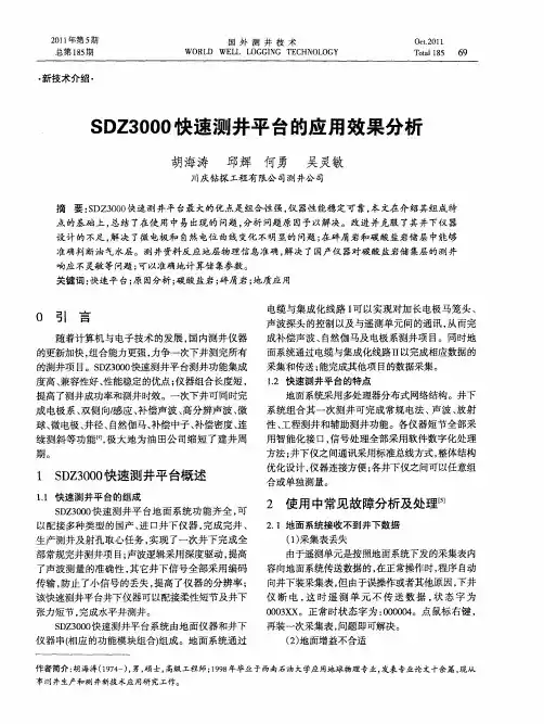
SDZ3000快速测井平台的应用效果分析
( ) 面系统 有问题 3地
在沙泥岩地层的井测井过程 中发现 , 使用感应 仪器上的 自 电位测量点, 然 在整个测量过程中s 曲 P
线几 乎无 幅度 差 , 呈直线 状 。但 是 电极上 的 s P曲线
用示 波器 观察 2 、 缆芯是否 有下发命令 信 5 号, 若无应检查地面 P M卡 。另外 , C 应定期对仪器 的各个部件 进行 紧固和检测 , 确保各板卡 接触 良 好。由于该地面系统采取板卡式插件 , 时常出现板 卡 与母 板接 触 不 良及板 卡 上 的集 成芯 片松 动 现 象 , 所 以测井施 工之前应对仪器的板卡及芯片进行检
准确判 断油 气水层 。测 井资料反 应 地层 物 理信 息准 确 , 解决 了国产仪 器对碳 酸 盐岩储 集层 的测 井
响应不灵敏等问题 ; 以准确地计算储集参数。 可 关 键词 : 快速 平 台; 因分析 ; 酸盐岩 ; 原 碳 碎屑 岩 ; 地质应 用 电缆与集成化线路 I 以实现对加长电极马笼头、 可 声波探头 的控制 以及与遥测单元 间的通讯 , 从而完
23 刻度 正 常 。 _ 测并 不正常
发生 发展 ~ 消亡阶段 , 使延长组形成 了一套完整
的生 、 、 储 盖组合 。姬塬 地 区陆源碎屑 物质主要 由石
英、 长石 、 岩屑和云母组成 , 由于沉积 、 成岩等条件的 改变 , 延长组与延安组碎屑含量差异明显。延长组
与延 安组 物性 特 征主 要是 低渗 油层 , 者属 于超 低 或
7 1
42 在 碳 酸盐岩 储层 中寻 找油气 层 .
在四川盆地的天然气储层其岩性主要是碳酸盐 岩, 储集层类 型大多是裂缝 一 隙型 , 向异性突 孔 各 出, 岩性结构复杂 , 给测井解 释与评价带来 了多解 性、 模糊性和不确定性 。如图 2 是利用 S Z 00 D 30 所 测 的四川气 田D Y井的飞仙关组 , Y 测井项 目与姬塬 油田的区别是 , 了放射性测井 , 多 感应换为双侧 向, 没有微 电极 测井 。在井段 2 2- 23 米处 , 66 63 自然伽 马值在 1—1A 1 2 8 P 之间, 岩性较纯。声波时差 l0 6 — 10 9 微秒/ , 米 补偿 中子 0 . . , —2 Pu 补偿 密度 2 2 5 . — 7 2 7 立方厘米 ,L . 克/ 7 孑 隙较发育。深 电阻率高阻背景 下 明显 降低 , 其值 70 10 欧姆. , 0 — 20 米 且深浅电阻率 呈明显正差异 。综合分析为气层 , 经过试油证实 , 结
SD-3000Ⅱ SMT 重工站说明书
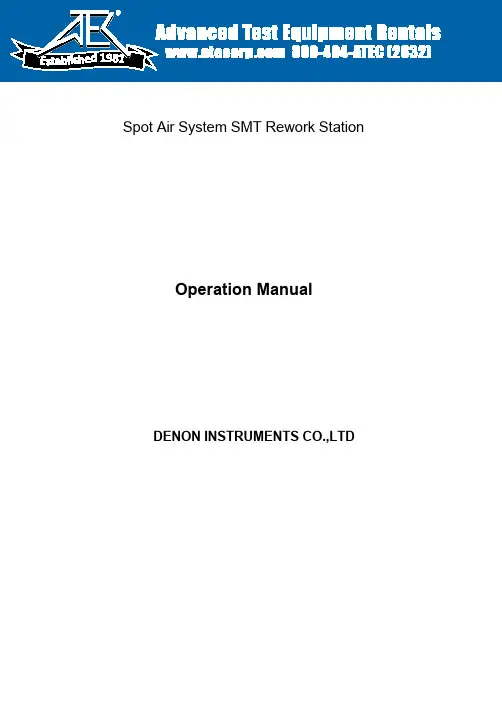
1981Spot Air System SMT Rework Station‚r‚c•|‚R‚O‚O‚O‡U‚c‚h‚b ‚q‚d‚v‚n‚q‚j‚r‚s‚`‚s‚h‚n‚m Operation ManualDENON INSTRUMENTS CO.,LTDDIC SD-3000‡U SMT Rework Station•¡I NTRODUCTIONThank you for your purchasing the SD-3000‡U SMD Rework Station.The SD-3000‡U is a highly reliable SMD rework station with hot air system that is applied for the removal and the placement of many shapes of QFP/SOP/BGA/Micro-Component (0603) and etc.When the solder of the components is melted in a brief time by the hot air from the oscillating nozzle, the components can be quickly removed by the vacuum pick.•¡FEATURES‚P•D The oscillation range of the nozzle can be adjusted up to 50 mm in the X axis (Right & Left) and/or Y axis (Back & Forth). This allows it to be used for any size of SMT parts up to 50mm.‚Q•D The temperature can be set and is displayed on the digital read out.‚R•D The hot air is controlled by a heater with thermocouple, closed loop feedback circuit.‚S•D For repeatability, there is a timer that allows the user to set up any run a complete heat cycle.‚T•D The operation can be easily stopped at anytime using the STOP button. After pushing the button, the nozzle will come up and the heater will automatically turn off. The air will continue to flow inorder to cool down the nozzle.‚U•D The vacuum pick comes standard and is used to quickly remove the SMT parts when the solder has melting.‚V•D The maximum PCB size that can be held is 420mm in depth and no limitation in width.‚W•D For removal and placement of the micro component, the air flow is adjusted to a minimum volume in order to control the reflow.•¡Machine Description and Accessories•¡Basic Set Up•¡Installation‚P•D Place the main body on a level surface.‚Q•D Before turning on the Power, please confirm that the transport screw (A butterfly screw) is removed.The transport screw is designed to protect the internal parts of the unit during transport.•¡Preparation‚P•D Turn on the Power Switch.‚Q•D Turn right the Z Axis Knob to the uppermost position.‚R•D Set the TIMER Knob to the maximum time.‚S•D Set the TEMP Knob for adjusting temperature to 5. This is approximately 450 degrees C on the digital panel5 •D Place the PCB on the PCB Holders and adjust the Base Plate so that the target part for removal ispositioned right under the Nozzle.•¡ Positioning of Nozzle6•D Push the START Button (Green color) or Auxiliary Start Switch to lower the Nozzle.7•D Turn left the Z Axis Knob to lower the Nozzle so that the Nozzle point is 1 mm above the surface of the target part.8•D Adjust the length of the X and Y oscillation by the X Axis Knob and the Y Axis Knob so that the Nozzle moves over the solder joint of the target part.9. For additional components, repeat steps 5-7.•¡ Removing the Component11. Push the START Button or the Auxiliary Start Switch once more to switch on the Heater. This willstart the air flow and will begin the reflow of the solder joints.12. The Vacuum Pick can be switched on anytime while the air blow is on.13. Watch the solder joint to confirm that the solder has melted.14. Place a finger on the air escaping hole of the Vacuum Pick and contact the Vacuum Pad to thesurface of the target part.15. Push the STOP Button. The Nozzle will come up and the Heater will turn off. Then the air pump willautomatically stop once the Nozzle has cooled down.16. If you need to reflow the component further, simply push the START Button again.¦Operation With Illustrations•¡Reworking Micro-ComponentsPlace a magnifier such as Camera or Microscope in front of the Operation Panel to magnify the target point. (We will recommend our optional camera for this.) When reworking Micro-Components, you can not use the START/STOP Buttons on the front of the operation panel. Instead, use the auxiliary switch of the side of the operation panel. Use the following steps for reworking Micro-Components.Make sure that the power switch is off then:‚P•D Place the optional Auxiliary Holder on the PCB Holder.‚Q•D Set the Blow Knob between 1 and 3, set the X and Y Axis Knob at 0.‚R•DWith the start button pushed on, switch on the power switch.‚S•D Set the temperature at 580 degrees C and the timer at approx.120 seconds on the Digital Panel.‚T•D When you turn the Power Switch on, the Nozzle will move forward at an angle toward the front of the machine. This is so that you can perform the rework using the magnifier.6. REMOVAL- Magnifying the target area, switch on the Auxiliary Start Switch.- Confirming the solder melting with eyes view, remove the component with the Vacuum Pick.Use the #20 for the suction nozzle. The #20 is the optional part.6. PLACEMENT- Place on the target area an adequate volume of flux, e.g., Koki-product TF-M201-6.- Switch on the Auxiliary Stop Switch to activate the suction pump. While the main body is off, the suction pump will be activated with the Auxiliary Stop Switch.- Using the vacuum pick, get a component from the tray to transfer to the target area. Use the #25 for the suction nozzle. The #25 is the optional part.- Use a Stainless Steel Probe to position the component. The SMT Probe is also available as an option.- Switch on the Auxiliary Start Switch to start reworking. You can observe the component making the self alignment with surface tension of the melted solder.7. Switch on the Auxiliary Stop Switch. And the Nozzle will automatically come up with a cooling state.At this time, the heating time is indicated on the Digital Panel. When the heating time is set in thetimer, the heating will automatically stop at the preset time.¦Recommended Air Flow for Rework ApplicationsThe air volume is adjusted with the Blow Knob.¦Recommendations for Rework Using the SD-3000‡U1. When using the Vacuum Pick, hold it like a pen. Placing a finger on the air escape hole and let thePick grab the component. Please see Step 5.2. At times, there can be a great difference in the time to reflow the first component and the followingcomponents. This is because the heater is generally cold when starting so the first component willtake a bit longer. Please keep this in mind when setting up the timers settings.3. When reworking the large PCB, it is possible that a bending or a warping occurs on the board.Please adjust the Nozzle height by the Z Knob to avoid hitting the board if it happens to warp.4. The bonding resin is at times used for the target component. In this case please use metal tweezersinstead of the Vacuum Pick for the removal.5. When removing the micro component like 0603, set the Blow Knob at minimum 1 and set the X & YAxis Knob at minimum 0. When placing the micro component, please use flux for surface mountwork like the Koki brand TF-M201-6.6. When the PCB Holders (Accessories) can not be utilized for the support of the PCB due to theexistence of the connectors fitted on the PCB, please use the PCB Support Pin that is also supplied as a standard accessory.7. When reworking large components, please use the Metal Frames for more effective heating and alsoto prevent the hot air from reflowing the near-by parts.8. When removing the DIPs or large BGAs, please preheat the reverse side of PCB at 120 degrees Cfor effective reworking. The PH-3100A is recommendable for this preheating.9. The small PCB is apt to move itself. In this case please put a weight on it to keep the position of thePCB.10. The removal time will vary according to the rework conditions, e.g., continuous or intermittent works,the size of components and the sort of PCB. When you setting the Timer, please take care of them. ¦Specifications•¡Major Parts for ReplacementRemarks: Filter (20-11-37) for Vacuum Pick will get dark in 10-20 hours of continued use in hot air. Once the filter has become darkened needs to be replaced.•¡Options- Camera for Rework of Micro Component- Auxiliary Holder for Small PCB- SMT Pin for Rework of Micro Component- Suction Nozzle #20 for Removal of Micro Components / #25 for Placement of Micro Component¦Recommended Item – Preheater PH-3100AWhen the SD-3000‡U is used together with PH-3100A, you can conduct the reworking works faster and more effective. Especially it is recommended for the rework of the ceramic PCB and/or the big PCB.•¡ Circuit Block Diagram•¡ MaintenanceThe SD-3000‡U is designed to be low maintenance. However the replacement of major parts will be needed if trouble occurs. And the consumable parts will have to be changed from time to time when required. Please follow the instruction stated below when the parts replacements is needed.Removal of the Cover PlateRemove the cover plate when replacing the major parts. Please remove the cover plate in the following steps.Removal of Cover Plate‚P•D D isconnect the Power‚Q•D Remove the screws in the Z Knob.‚R•D Remove all of 14 screws fitted to the CoverPlate.‚S•D When removing the Top Cover of the FrontPanel, pull up the Top Cover, opening the under side of the Top Cover outwards.A. Replacement of Heater Nozzle1. Disconnect the AC cord.2. Remove the Top Cover of the Front Panel.3. Remove the Heater Lead Wire of the Connector.4. Replace the Heater Nozzle.5. Assemble the Nozzle so that the Nozzle Tip is 2 to 3 mm distant from the surface of the PCB asillustrated below.B. Replacement of Main PCB1. Disconnect the AC cord.2. Remove the Cover Plate to access the Main PC Board.3. Remove all connectors.4. Remove the fitting parts (white) of the Main PC Board.5. Remove the Main PC Board.6. Re-assemble the new Main PC Board.C. Replacement of Filter for Vacuum PickThe Filter of the Vacuum Pick is housed in the Base Frame. Remove the Hose Joint fitted at the insertion port of the Base Frame by wrench, and take out the old Filter.D. Replacement of Suction Pad for Vacuum PickThe Suction Pad is of rubber. When the rubber is injured or slackened, replace it.•¡Trouble ShootingThe trouble shooting diagram below is an index so that you can quickly identify the cause of problem and restore the equipment to normal operation. If the problem cannot be solved please contact DENON directly or the service agent for further technical information on the repairs.1112 SMT Solder Cleaner - SC-200 (Internal Pump) & SC-300(Shop Air)1. By giving the heating element 120 watts of power, this solder cleaner has the power to keep the tip at or near the set temperature during the heaviest SMT continuous cleaning. The higher power and better recovery result in two significant benefits. First, there is much less clogging than with standard desoldering units. Second, there is no need to increase the tip temperature which therefore results in longer tip life.2. By adding a hot air blowing feature during the cleaning, they are able to preheat the area to be soldered before the hot tip moves to the solder joints or pads. The hot air also keeps the hot tip from cooling while desoldering since it is not vacuuming cool air. This further prevents the clogging typically found in other desoldering tools.3. Both the SC-200 & Sc300 systems are equipped to handle N2. The following specifications are for SC-200.Main Body GunCautionThe SD -3000S ‡U is manufactured and sold for the purpose of use in the factory and/or laboratory. Since the nozzle is hot, you must not touch it before the nozzle cooling down. And since the removed SMT parts are also hot, y ou m ust n ot t ouch i t b efore i t •fs c ooling d own. E ven i f t he s top b utton i s p ushed,the machine is still in operation because the activated air pump cools down the nozzle. So do not turn off the power switch while the air pump operating. Otherwise, themachine will be damaged due to the overheating.- - - - - - - - - - - - - - - - - - - - - - - - - - - - - - - - - - - - - - - - - - - - - - - - -Manufacturer DEN -ON INSTRUMENTS CO.,LTD Exporter DIC TRADING CO.,LTD1-26-10 Sekimachi -higashi, Nerima, Tokyo, JapanTEL: 81(Japan)-3(Tokyo)-3929-6800 FAX: 81-3-3929-7441。
XZ-3000技术和使用说明书V2.8
六、显示模块 ................................................................. 14
6.1 描述............................................................................................................................................................. 14 6.2 主要功能..................................................................................................................................................... 14 6.3 指示灯......................................................................................................................................................... 14 6.4 按键............................................................................................................................................................. 15 6.5 显示内容................................................................................................................................................................................................................................................................................. 错误!未定义书签。
Standard3000中文操作手册part1
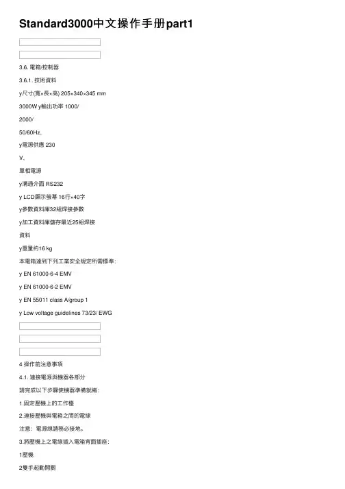
Standard3000中⽂操作⼿册part13.6. 電箱/控制器3.6.1. 技術資料y尺⼨(寬×⾧×⾼) 205×340×345 mm3000W y輸出功率 1000/2000/50/60Hz,y電源供應 230V,單相電源y溝通介⾯ RS232y LCD顯⽰螢幕 16⾏×40字y參數資料庫32組焊接參數y加⼯資料庫儲存最近25組焊接資料y重量約16 kg本電箱達到下列⼯業安全規定所需標準:y EN 61000-6-4 EMVy EN 61000-6-2 EMVy EN 55011 class A/group 1y Low voltage guidelines 73/23/ EWG4 操作前注意事項4.1. 連接電源與機器各部分請完成以下步驟使機器準備就緒:1.固定壓機上的⼯作檯2.連接壓機與電箱之間的電線注意:電源線請務必接地。
3.將壓機上之電線插⼊電箱背⾯插座:1壓機2雙⼿起動開關3RF (與換能器連接)4電源4.1.1. 主動溝通裝置5RS232插座 (9孔D-sub插座)6數位輸⼊ (25孔D-sub插座,序列埠)7數位輸出 (25孔D-sub插座,序列埠)其他資料請⾒第⼋章”資料分析”,插座配置請⾒第九章”主動溝通與信號傳送”。
4.1.2. 壓縮空氣源:最⼤7 bar;105 psi依下列指⽰轉動壓縮空氣閥(21):4.將壓縮空氣喉(21a)與壓縮空氣供應源連接。
5.將壓縮空氣閥(21)轉⾄⼯作位置。
注意:若輸⼊壓縮空氣壓⼒⼤於7 bar,附加安全氣閥會⾃動開啟釋放過多的空氣壓⼒。
4.1.3. 裝備隔⾳罩SSK-H1ADG電箱電源2數位輸⼊ (25孔D-sub插座,序列埠) 3數位輸出 (25孔D-sub插座,序列埠) 4壓機5雙⼿起動開關6RF (與換能器連接)拆除隔⾳罩後⽅⾯板可調整壓機,卸除或裝備隔⾳罩。
4.2. 操作及顯⽰元件4.2.1. 壓機1 換能器外罩內藏超⾳波發振系統及電源線。
SDS3000使用说明书3.0
高抗干扰设计 主控电脑板采用抗干扰设计,能在较恶劣的环境下连续可靠地工作。主控电脑板 内置开关电源,核心部件均单独供电,供电电压从 DC15V 到 DC24V 均可;硬件 及软件双重“看门狗”,系统意外故障时能够自恢复运行;光耦输入,继电器输 出,主控电脑板与外部环境完全隔离;高性能抗干扰 RS485 通讯器件。
第二章 串行通讯内选板说明
1. 内选控制板概述
内选控制板提供 16 点双向口(输入输出共用端口),每一点对应一层楼的内 选信号,I/O1 接第一站的内选信号,I/O2 接第二站的内选信号,其它依此类推。 内选控制板应通过接点 PE 可靠接地,按钮信号的公共端应接至 24V-,应答灯信 号的公共端应接至 24V+。站数高于 16 站时,需要再加一块内选控制板,注意这 两块内选控制板的软件并不相同,具体情况请向厂家咨询。
电源指示一直亮主cpu工作指示一直闪烁通讯口1通讯指示正常通讯时闪烁操作按键用于状态查询及参数修改enter进入确认键用于进入下一级窗口或设定要修改的参数值esc返回取消键用于返回上一级窗口或取消已修改的参数值up上翻增加键用于菜单间向上翻查或增大要修改的参数值down下翻减少键用于菜单间向下翻查或减小要修改的参数值纽扣电池用于给实时时钟芯片提供电源时钟芯片为系统运行提供时间基准
系统功能在不断的更新,不同的产品功能不尽相同,使用说明书并未将所有系统 功能一一罗列。系统使用了全中文界面,采用的是电梯界通用的术语,用户界面 友好,技术的改进不会对使用造成不便。
SDS-3000系列是一套全电脑控制智能型串行通讯电梯专用控制系统。该系统全面 引进PHILIPS尖端技术,加上公司开发工程师、市场工程师及应用工程师的不懈 努力和超群智慧,将现在及未来的各种需求融入产品之中,充分满足用户的要求。 SDS3000的主要特点是:
ZL3000电梯控制系统调试手册
ZL3000电梯控制系统调试手册安徽中菱电梯有限公司第一章系统操作及参数说明1.1概述手持操作器的液晶显示为调试、维修人员提供友好的人机交流界面。
调试、维修人员可以通过液晶显示及键盘操作对电梯系统进行观测、设置。
具体内容如下:(1)监视电梯状态:自动、检修、司机、消防、锁梯等;(2)观测:井道位置、电梯速度、I/O口、故障信息、呼梯、内选、通讯等;(3)设置参数;(4)井道自学习;(5)保存参数;(6)设置新密码等。
1.2键操作说明手持操作器如下图所示,液晶显示器下面有六个键,六个键的排列及定义如下:各按键作用如下说明:“Menu”—除井道自学习或保存参数外,按该键则无条件返回主界面。
“Enter”—进入下一级菜单、修改数据后的确定键、指令登记确定键。
“Esc”—返回上一级菜单、取消键。
“>”—光标键(循环右移),在主菜单时按该键进入通讯状态界面。
“∧”—上翻页键、设置参数时加一键或选择参数时Yes(ON)键。
“∨”—下翻页键、设置参数时减一键或选择参数时NO(OFF)键。
1.3液晶显示流程图及参数说明1.3.1主菜单显示当前楼层、运行方向、运行状态、故障状态、门锁状态、运行速度。
电梯状态:INSP检修,MANU司机,AUTO自动,FIRE消防,PARK锁梯。
故障状态:电梯有故障时显示ER=#;无故障空白。
门锁状态:CLOSE门关,OPEN门开。
当前楼层:电梯所处楼层(实际楼层)。
1.3.2校验密码需要设置保存参数时,必须使电梯置于检修状态,正确输入用户级密码后可进入参数设置菜单.1.3.3监视菜单及参数设置菜单▲:电梯额定速度、电机额定转速、编码器脉冲数三个参数很重要,应根据设备的标称值设定,否则电梯不能正常运行(如测速不准,换速点出现偏差等)。
当三个参数中任何一个改变时,必须重新进行井道自学习后方可正常运行。
当系统接收的反馈脉冲为分频后的脉冲时,设定编码器脉冲数应进行折算,而非编码器的实际值。
SDS3000A说明书
10
SDS-3000A Super Lift System Controllers
1.2.4输出端口定义
输出部分主要是控制电梯的运行功能,作为电梯控制的执行部件。分布在J3,J4,J5,J7,
J8上。
输出部分的开关量输出属性如下:
输出点数
16
输出形式
继电器接点输出
负载电压 触点容量 触点寿命
额定输出 允许范围 阻性负载 感性负载 机械寿命 电气寿命
01 01 01 01 01 01 01 01 10 10 10 10 10 01
9
SDS-3000A Super Lift System Controllers
X15 J11.7 Input
开门按钮
开门按钮
01
X16 J11.8 Input
关门按钮
关门按钮
01
X17 J12.1 Input
开门限位
4
SDS-3000A Super Lift System Controllers
安全注意事项
安全注意事项不仅适用于主控电脑板,还适用于与主控电脑板配套的其它各种电子及电 气设备。
客户应对收到的货物开箱检查,请仔细确认在运输中是否有破损现象,所收货物是否与 订货要求一致。若发现有遗漏或不相符的情况,请速与供货商联系解决。
3
SDS-3000A Super Lift System Controllers
前言
非常感谢使用SDS3000系列产品。本说明书叙述了SDS3000A产品的安装、调试、维护方面 的内容。在使用本产品前,请谨慎认真阅读本说明书,特别是有关安全注意事项。在全面了 解本产品的性能特点后,才可以使用本产品。
类型 交流双速 下行接触器
管理信息系统之实验报告之速达3000操作方法
实验报告课程名称管理信息系统实验项目名称速达3000子系统分析与设计实验班级与班级代码实验室名称(或课室)ssj-301专业审计学任课教师学号:姓名:实验日期:2011-06-25广东商学院教务处制姓名成绩评语:指导教师(签名)年月日说明:指导教师评分后,学年论文交院(系)办公室保存。
速达3000pro“5555555”子系统分析与设计实验实验目的:实验条件:优秀管理信息系统软件“速达3000pro”(C/S结构,Interbase大型数据库单机版或网络版)为实验平台。
预备知识:实验内容:1、熟悉“5555555”操作与功能分析:进入界面、工资数据录入、支付工资、计件数据录入、费用分配的操作与分析2、掌握“5555555”子系统的“数据三层结构、业务导航图形化的界面”分析、设计与操作。
3、了解以“表单”方式表示的55555管理子系统“业务流程”。
4、熟悉数据结构(三层结构)与数据库操作。
5、掌握数据结构(三层结构)与数据库分析、设计。
实验步骤、结果分析:1、“登陆”速达3000pro的“进入界面”设计与操作。
界面如下箭头所示步骤:进入后界面如图:2、“工资项目定义”操作及功能分析(编制表单)如下图箭头步骤所示为工资项目定义中“增加工资项目”的功能操作:通过这个功能对职工工资进行详细分享,增加、修改、删除各工资项目,工资项目还分为增项和减项。
从而方便日常的工资管理。
如下图是工资项目定义中工资项目“计算公示”的功能操作:通过这个功能的公式项目整合了较为分散的工资项目,方便进一步确定职工工资数额是如何的得出来的。
3、“工资项目分类”操作及功能分析(编制表单,界面如下)如下图的箭头所示是对“工资项目分摊类别”的操作:通过这个功能确定各工资类别所应属于的工资项目分摊类别,便于公司成本等财务管理。
4、“计件数据录入”操作及功能分析如下图的箭头所示是“计件数据录入”的操作:这个功能有工种、单位工价、计件数量、加班工资等全面详细纪录每位员工的计件工资,同时还有复制上一条记录等节省工作量的功能。
SDZ-3000测井平台在中原油田的成功应用
2 S Z一3 o D O o测 井 平 台 l j
2 1 地 面仪 部分 .
地面仪由采集箱 、 P U S电源、 高压电源 、 显示器 、 记 录仪 、 计算机等部分组成。与原有测井地面系统 比较 ,
该 系统 的硬件 资 源智 能 化 , 置 机 通 过 标 准 接 口很 灵 前 活地 控时向井下仪发送控制命令 , 提高了石油测井可靠性 。
3 S Z一30 测 井平 台在 中原 油 田得 应用 实例 D 00
S Z一30 D 0 0型测 井 平 台从 移 交 到 投 产 , 井 曲 线 测 合 格率 达 10 , 等率 达 8 %以 上 。特 别 在 对 深 井 0% 优 5 的测量 验证 中 , 仪器可 经受 相 当长 时间高 温高压 , 部 大
双感应 一 八侧 向中的中感应 曲线都有 明显的锯齿波
状 。这些 都给解 释人 员进 一步 认识 测井 曲线 提供 了新 的依 据 。通 过 对 2 0口完 井 分 析 , S D 0 0仪 器 对 与 K 30
比 ,D S Z一30 0 0测井 平 台大 大 缩短 了在 中原 复 杂 井 况
时监控井下仪的工作状态、 工作温度等信息 , 可屏蔽任 意单 只仪 器 , 提高 一次 测井 成功 率 。采用 数据 库技 术 ,
提供一 种 经济有 效 的刻 度文 件 、 井数 据 文 件 的管 理 测
方法 。
硬件系统 : 该系统配备两 台 P Ⅳ工控机 , 主要完成 数据 处理 工 作 。通 过 网络 与前 置 采 集 机 进 行 数 据 交 换 。前置采集机接收主机命令 , 控制系统硬件工作 , 利 用双 口 R M 和 FF A IO技术 , 与各信号处理卡快速交换 数据 、 打包、 给主机。前置采集 机采用 标准 I 传 c总 线技术 , 使得接 口标准化 , 易于扩展 。深度系统利用马 丁代克双轮在线式马达 , 公英制切换。
Standard3000中文操作手册part4
9.3. STO_3壓機控制訊號針腳編號訊號說明1 +24VDC_PRESS_OUT 供應壓機+24V DC電源2 HOMEPOSITION_IN 原始位置感應器訊號輸入3 PU_PRESS_IN PU開關(PU-switch)訊號輸入4 SSW_1_PRESS_IN 安全開關1 (6mm) 訊號輸入5 SSW_2_PRESS_IN 安全開關2 (6mm) 訊號輸入6 MV_1_OUT 電磁閥1訊號輸出7 MV_2_OUT 電磁閥2訊號輸出8 SSW_1_PRESS_OUT 安全開關1 (6mm) 訊號輸出9 SSW_2_PRESS_OUT 安全開關2 (6mm) 訊號輸出10 INC_A_IN 行程測量訊號輸入(A軌)11 INC_B_IN 行程測量訊號輸入(B軌)12 PRESSURE_C_AIN 指針模擬系統壓力輸入訊號13 TRIGGER_C_AIN 指針模擬觸感起振器(偵測壓力差)輸入訊號14 24VDC_DELAY_OUT PU開關之延遲電流供應輸出訊號電源接地之訊號輸出15 GND24VDC_PRESS_OUT9.4. STO_5雙手起動開關控制訊號針腳編號訊號說明1 Nc2 START_1_OUT 起動開關1訊號輸出3 START_1_NC_IN 起動開關1訊號輸入(正常關閉)4 START_1_NO_IN 起動開關1訊號輸入(正常開啟)5 START_2_OUT 起動開關2訊號輸出6 START_2_NC_IN 起動開關2訊號輸入(正常關閉)7 START_2_NO_IN 起動開關2訊號輸入(正常開啟)8 24VDC_DELAY_OUT 控制緊急停止掣之延遲電源供應9 EMERGENCY_1_IN 緊急停止掣1訊號輸入10 EMERGENCY_2_IN 緊急停止掣2訊號輸入11 nc電源接地之訊號輸出12 GND24VDC_PRESS_OUT10 不當使用之錯誤訊息正常ADG錯誤ADG訊號焊接週期階段0>1促動器下壓(焊接前下壓行程)1>2下壓速度漸緩2>3增加功率3>4焊接4>5固化5>6促動器上行裝備隔音罩之正常ADG裝備特殊促動器之ADG焊接週期階段0>2促動器下壓(焊接前下壓行程)1>3下壓速度漸緩2>4增加功率3>5焊接4>6固化5>7促動器上行11 機械維護11.1. 錯誤群組說明錯誤群組002 電箱錯誤003 壓機錯誤004 隔音罩錯誤005 限制值錯誤006 數位控制錯誤007 硬體錯誤008 RS232錯誤009 CANopen錯誤020 限制值警告021 參數值警告11.2. 錯誤代碼詳細說明電箱錯誤(錯誤群組 002:xxx)錯誤代碼優先性說明002:000 低達到最大功率損失(Pv測試)002:001 高電源電壓過低002:002 高Power pack +12V defective002:003 高Minimal level control final stage002:004 高溫度過高002:005 低頻率低於最低值002:006 低頻率高於最高值002:007 低換能器電壓高於最大值002:008 低出力過載002:009 低Full level control of the final stage reached 002:010 低未連接換能器壓機錯誤(錯誤群組 003:xxx)錯誤代碼優先性說明003:000 低測量行程時發生錯誤003:001 低閥門錯誤003:002 低雙手起動開關錯誤003:003 低促動器未回到原始位置Abort 003:004 低安全開關(最後6mm)錯誤003:005 低超過最大焊接週期時間003:006 低焊接過程中斷003:007 低觸感起振器設定錯誤003:008 低超音波起振錯誤003:009 低系統壓力過低隔音罩錯誤(錯誤群組004:xxx)錯誤代碼優先性說明004:000 低安裝錯誤004:001 低開始焊接時工作窗無法開啟004:002 低時間超過而降下工作窗004:003 低時間超過而升起工作窗004:004 低隔音罩門打開004:005 低焊接週期中打開工作窗限制值錯誤(錯誤群組005:xxx)錯誤代碼優先性說明005:000 低超過設定的最大時間005:001 低低於設定的最小時間005:002 低超過設定的最大能量005:003 低低於設定的最小能量005:004 低超過設定的最大出力005:005 低低於設定的最小出力005:006 低超過設定的最大行程005:007 低低於設定的最小行程005:008 低超過設定的最大行程差005:009 低超過設定的最小行程差005:010 低到達設定的良品數數位控制錯誤(錯誤群組006:xxx)錯誤代碼優先性說明006:000 低焊接週期停止006:001 低設定超音波停振1006:002 低設定超音波停振2006:003 低設定重設006:004 低退出外置起動006:005 低需要外製起動006:006 低資料傳遞輸入訊號錯誤硬體錯誤(錯誤群組007:xxx)錯誤代碼優先性說明007:001 高輸出群組1短路007:002 高輸出群組2短路007:003 高輸出群組3短路007:004 高輸出群組4短路007:005 高輸出群組5短路007:006 高輸出群組6短路007:007 低壓力輸入低於1mA007:008 低觸感起振器輸入低於1mA007:009 低數控振幅輸入超過120%或12VRS232錯誤(錯誤群組008:xxx)錯誤代碼優先性說明008:001 低資料溢出錯誤(符號丟失)008:002 低同等性錯誤(同等性符號錯誤)008:003 低結構錯誤(無有效停止符號→bit rate錯誤) 008:004 低傳輸中斷(位元組過長→bit rate錯誤) 008:005 低未連接接收器CANopen錯誤(錯誤群組009:xxx)錯誤代碼優先性說明009:001 低 SDO讀取錯誤(暫停)009:002 低 SDO寫入錯誤(暫停)009:003 低 SDO服務(錯誤參數)009:004 低 SDO無法進入(設定值範圍錯誤)009:005 低 SDO其他錯誤限制警告(警告群組020:xxx)錯誤代碼優先性說明020:000 警告超過設定的最大時間020:001 警告低於設定的最小時間020:002 警告超過設定的最大出力020:003 警告低於設定的最小出力020:004 警告超過設定的最大功率020:005 警告低於設定的最小功率020:006 警告超過設定的最大行程020:007 警告低於設定的最小行程020:008 警告超過設定的最大行程差020:009 警告低於設定的最小行程差參數警告(警告群組021:xxx)錯誤代碼優先性說明021:000 警告資料組是空的 / 未載入資料組021:001 警告警告資料未刪除11.3. 清潔機器注意:清潔與維護須由受過專業訓練之人員操作,開始維護前,確認電源與壓縮空氣源均未接上。
