Stromag Braker制动器使用说明书
STROMAG盘式制动器

STROMAG STROMAG制动器、STROMAG盘式制动器、STROMAG限位开关、STROMAG 电磁离合器、STROMAG电磁离合器、STROMAG抱闸摩擦片、STROMAG角度编码器、STROMAG驱动模块。
德国STROMAG集团是机械动力传动技术领域中各种难题的解决者。
我们通过与客户设计部门的密切合作,在传动链方面努力开发有创新思维的解决方法,并最终应用在相应的产品生产中。
德国STROMAG是一个能够在世界范围提供如此广泛和完善服务的制造商。
我们通过对生产中的工艺流程和实际操作方面的深入研究和严格控制,确保产品在各相关领域中处于技术地位。
更通过DIN ISO9001 质量体系的认证,使我们在给各个领域提供技术支持方面发挥着领导者的巨大作用。
STROMAG的工程师拥有优异的技术知识。
他们将战略焦点明确地集中在生产和应用方面的核心技术上,使我们能在极短的时间内为客户解决机械传动领域的难题,并提供完美的解决方案。
产品包括:德国STROMAG制动器、STROMAG盘式制动器、STROMAG限位开关、STROMAG电磁离合器、STROMAG电磁离合器、STROMAG抱闸摩擦片、STROMAG角度编码器、STROMAG驱动模块。
上海智川工贸有限公司专业销售德国STROMAG制动器、STROMAG盘式制动器、STROMAG限位开关、STROMAG电磁离合器、STROMAG电磁离合器、STROMAG抱闸摩擦片、STROMAG角度编码器、STROMAG驱动模块。
德马格中文操作说明书

液压顶出 后退 / 前进
气阀 1-4 打开
中子 抽芯 / 进芯
自动安全门 打开 / 关闭
Rotary table index bolt move in / move out
模厚调整 增加 / 减小
旋转模板 逆时针 /顺时针
提示 “模厚调整”按钮只针对曲轴式机床。“自动安全门”和“气阀 1-4”按钮只有当这些功 能配置以后才起作用。“Rotary table latches”, Rotary table index bolt” and “旋转模板”应 用于带转转模板的多色注塑 。
Sfu服EnRc务tVio页InC面Egr功oup 能组
Afu报LnAc警tRio功Mn能Sgr组oup
Fig. 2: 功能选择键
1.2 手动功能键
在手动和点动模式下可通过下面的按钮(见Fig. 3 和 Fig. 4)进行相应的操作。 Fig. 3: 手动模具装置功能
模具 打开 / 闭合
Rotary table latches move in / move out
4.4
帮助功能键和专家系统 .......................................................................................................19
5
频幕 ..........................................................................................................20
Pfu程RnOc序tGio功Rn能AgrM组oSup
Process 过Pfu程RnOc控tCio制EnS功gSr能oCu组pONTROL
关键性设备操作手册.doc

1.锚缆机操作规程----------------------------------------------------------------4 2.首尖舱污水遥控排水系统操作规程-----------------------------------------6 3.压载控制台操作规程-----------------------------------------------------------74. 货舱进水检测装置操作规程--------------------------------------------------95. 货舱污水处理操作规程--------------------------------------------------------116.报警监视系统操作规程--------------------------------------------------------127. 和面机/电炒锅操作规程------------------------------------------------------ 148. 电灶的使用与保养--------------------------------------------------------------159.粉碎机操作规程-----------------------------------------------------------------1610.烤箱的操作规程-----------------------------------------------------------------1711. 蒸馒头/蒸饭机的操作规程------------------------------------------------------1812. 货舱作业的安全规定----------------------------------------------------------1913. 甲板作业的安全规定---------------------------------------------------------2014. 开关舱作业的安全规定------------------------------------------------------2115. 系解缆作业的安全规定------------------------------------------------------2216. 舷外、水上作业的安全规定------------------------------------------------2417. AIS操作规程-------------------------------------------------------------------2518. C站操作规程-----------------------------------------------------------------2719. EPIRB 操作规程---------------------------------------------------------------2820. F站操作规程-----------------------------------------------------------------2921. GPS NAVIGATOR操作规程--------------------------------------------------3022. NAVTEX 操作规程-------------------------------------------------------------3323. NBDP 操作规程----------------------------------------------------------------3424. VDR 操作规程------------------------------------------------------------------3625. VHF 操作规程------------------------------------------------------------------3726. 电子海图操作规程------------------------------------------------------------3827. 雷达使用操作规程------------------------------------------------------------3928. 气象传真机操作规程---------------------------------------------------------4429. 自动舵操作规程---------------------------------------------------------------4730. 驾机联系制度------------------------------------------------------------------4831. 驾驶台规则---------------------------------------------------------------------5132. EEBD 操作规程----------------------------------------------------------------5233. 火警控制面板操作规程-----------------------------------------------------5334. 机舱大型二氧化碳灭火系统操作规程-----------------------------------5435. 机舱水雾灭火系统操作规程-----------------------------------------------5536. 救生筏释放程序--------------------------------------------------------------5637. 救生艇操作规程--------------------------------------------------------------5738. 消防员装备操作规程--------------------------------------------------------5839. 机炉舱规则--------------------------------------------------------------------6040. 机舱值班制度-----------------------------------------------------------------6241. 检修作业注意事项-----------------------------------------------------------6642. 主机操作规程-----------------------------------------------------------------6743. 副机操作规程-----------------------------------------------------------------6944. 燃油锅炉操作规程-----------------------------------------------------------7045. 主空压机操作规程-----------------------------------------------------------7246. 空调装置操作规程-----------------------------------------------------------7347.燃油分油机操作规程--------------------------------------------------------7448. 滑油分油机操作规程--------------------------------------------------------7549. 主机滑油泵操作规程--------------------------------------------------------7650. 主机缸套水泵操作规程-----------------------------------------------------7751. 主海水泵操作规程-----------------------------------------------------------7852. 重油驳运泵操作规程--------------------------------------------------------7953. 造水机操作规程--------------------------------------------------------------8054. 油水分离器操作规程--------------------------------------------------------8155. 生活污水处理装置操作规程-----------------------------------------------8256. 应急发电机操作规程--------------------------------------------------------8357. 应急救火泵操作规程--------------------------------------------------------8458. 应急空压机操作规程--------------------------------------------------------8559. 冰机操作规程-----------------------------------------------------------------8660. 焚烧炉操作规程--------------------------------------------------------------8764. 主配电板操作规程-----------------------------------------------------------8865. 应急配电板操作规程--------------------------------------------------------89 63. 压载泵操作规程--------------------------------------------------------------90目录64. 消防通用泵操作规程---------------------------------------------------------9165. 污水泵操作规程---------------------------------------------------------------9266. 机舱电力中断应急操作------------------------------------------------------9367. 触电的预防和急救------------------------------------------------------------9568. 总用电瓶及充放电板操作规程---------------------------------------------9669. 机舱报警检测系统操作规程------------------------------------------------9770. 机舱局部灭火系统操作规程------------------------------------------------9871. 机舱水雾灭火系统高压泵操作规程---------------------------------------9972. 主机机侧应急操作规程------------------------------------------------------10073. 主机盘车机操作规程---------------------------------------------------------10174. 饮水消毒柜操作规程---------------------------------------------------------10275. 砂轮机操作规程---------------------------------------------------------------10376. 气焊作业安全规定------------------------------------------------------------10477. 电焊作业安全规定------------------------------------------------------------10578. 车床作业安全规定----------------------------------------------------------10679. 救生艇机操作规程------------------------------------------------------------10780. 油渣泵操作规程---------------------------------------------------------------10881. 钻床作业操作规程------------------------------------------------------------10982. 火警T1016控制面板操作规程---------------------------------------------11083. 舵机操作规程------------------------------------------------------------------112锚缆机操作规程O P E R A T I O N I N S T R U C T I O N S F O R M O O R I N G W I N C H&W I N D L A S S 一、绞缆机操作的注意事项1)操作前必须要检查以下事项:●离合器的位置,齿轮箱上档位杆的位置,传感器上的指示灯,●检查刹车杆及刹车带是否完好,工作是否正常,●缆绳的出绳方向是否与刹车带底部连接块侧一致,●检查滚筒转动方向是否与操作杆指令方向一致,●检查所有的油脂润滑点,油位是否符合要求。
盘式刹车使用手册

盘式刹车使用手册盘式刹车使用手册一、工作原理:操作台包括刹车阀组件、驻车阀组件、控制阀组、管路压力表等,其液压原理见图四。
工作制动:工作制动是由刹把控制刹车阀9实现的。
刹车阀为手动比例减压阀,阀的输出压力随着拉动刹把而呈比例变化,对应刹把所处的不同位置,刹车阀的输出压力由0到最大系统压力变化。
刹把拉动角度越大,工作钳油缸的压力就越大。
刹把推到原始位置,阀输出压力为0,工作钳松闸。
每个回路中设有单向节流阀,在工作钳制动时起缓冲作用,使制动力逐渐施加,避免因操纵过猛而对设备产生不良影响。
驻车制动:驻车制动阀(13)为手动换向阀,拉动手柄,驻车驻车制动阀换向,使安全钳油缸卸压,弹簧力使安全钳实现驻车制动。
解除驻车制动时,必须先将刹把拉至“刹”位,使刹车阀(9)的输出压力控制误操纵保护阀(15)换向,再推动驻车制动阀手柄,将压力油输入到安全钳油缸,克服碟簧力,解除驻车制动。
注意:解除驻车制动时,必须先拉动工作制动刹把,再推驻车制动阀手柄方能解锁。
该回路中设有单向节流阀(18),在安全钳制动时起缓冲作用,1、调试前的准备工作:a、检查管汇的连接,确保无误,特别是P1的连接,若连错,会发生顿钻事故。
b、检查油箱液面。
C、检测蓄能器充氮压力,确保充氮压力为4MPa。
d、开启吸油口截止阀、柱塞泵泄油口截止阀;关闭蓄能器组截止阀。
若使用场合不需冷却器工作,则将冷却器旁路截止阀开启;若需要冷却器工作,则将冷却器旁路截止阀关闭。
e、点动电机,检查旋转方向是否正确。
2、调试a、启动电机。
b、调节系统额定压力、最大压力调节步骤如下:启动一台泵电机组。
松开安全阀螺帽并按顺时针方向旋转,调节至大约3/4的位置。
拆下泵的调压阀保护帽,松开泵的调压阀保护帽。
用内六方扳手顺时针方向转动螺钉以增大压力。
观察系统压力表MP读数,到9.5 MPa时为止。
如果调节的同时,压力停止上升,则转动安全阀少许。
交替调节低压力的安全阀或柱塞泵,直到MP压力表显示为9.5 MPa。
斯沃伯格刹车系统BSFH D500双杆双扁平刹车盘数据手册说明书
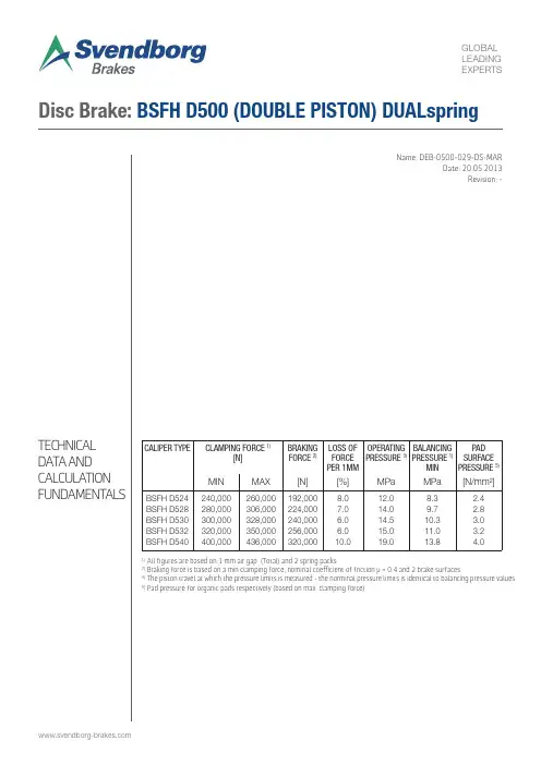
TECHNICAL DA T A AND CALCULA TION FUNDAMENT ALSName: DEB-0500-029-DS-MARDate: 20.05.2013Revision: -Disc Brake: BSFH D500 (DOUBLE PISTON) DUALspring1) All figures are based on 1 mm air gap (Total) and 2 spring packs2) Braking force is based on a min clamping force, nominal coefficient of friction μ = 0.4 and 2 brake surfaces.3)The piston travel at which the pressure limits is measured - the norminal pressure limits is identical to balancing pressure values 5)Pad pressure for organic pads respectively (based on max. clamping force)CALIPER TYPECLAMPING FORCE 1)[N]BRAKING FORCE 2)LOSS OF FORCE PER 1MM OPERATING PRESSURE 3)BALANCING PRESSURE 1)MIN PADSURFACE PRESSURE 5)MINMAX[N][%]MPaMPa[N/mm²]BSFH D524BSFH D528BSFH D530BSFH D532 BSFH D540240,000280,000300,000320,000 400,000260,000306,000328,000350,000 436,000192,000224,000240,000256,000 320,0008.07.06.06.0 10.012.014.014.515.0 19.08.39.710.311.0 13.82.42.83.03.24.0SpecificationThe braking torque M B is calculated from following formula where:a is the number of brakes acting on the discF B is the braking force according to table above [N] or calculated from formula D O is the brake disc outer diameter [m]The actual braking torque may vary depending on adjustment of brake and friction coefficient.M B = a · F B ·[Nm](D 0 - 0,2)2DUALSPRING Weight of caliper without bracket: Approx. 780 kg Overall dimensions without base plate: 698 x 530 x 533 (+C) mm Pad width: 200 mm Pad area: (organic) 110,000 mm 2 (*) Max. wear of pad: (organic) 10 mm (*)Nominal coefficient of friction: μ = 0.4 Total piston area - each caliper half: 2 x 145 cm 2 = 290 cm 2 Total piston area - each caliper: 4 x 145 cm 2 = 580 cm 2 Volume for each caliper at 1 mm stroke: 60 cm 3 Volume for each caliper at 3 mm stroke: 180 cm 3 Actuating time (guide value for calculation): 0.4sec Pressure connection/P-port: G3/8, ISO 288Air breathing connection/A-port: G3/8, ISO 288 Drain connection/L-port: G1/4, ISO 288 Recommended pipe size: 16/12 mm Operating temperature range - general from -20°C to +70°C(For temperatures outside this range contact Svendborg Brakes)(C = Brake disc thickness)(*) On each brake pad.BRAKING TORQUECALCULATION FUNDAMENTALSF B = F C · 2 · µDisc Brake: BSFH D500 (DOUBLE PISTON) DUALspring。
(完整word版)鼓式制动器说明书
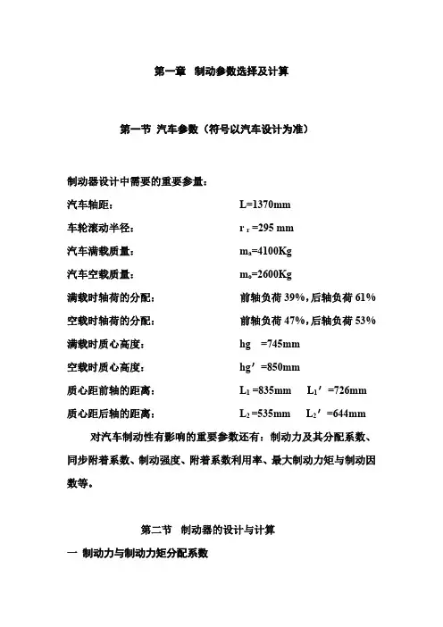
第一章制动参数选择及计算第一节汽车参数(符号以汽车设计为准)制动器设计中需要的重要参量:汽车轴距:L=1370mm车轮滚动半径:r r =295 mm汽车满载质量:m a=4100Kg汽车空载质量:m o=2600Kg满载时轴荷的分配:前轴负荷39%,后轴负荷61% 空载时轴荷的分配:前轴负荷47%,后轴负荷53% 满载时质心高度:hg =745mm空载时质心高度:hg'=850mm质心距前轴的距离:L1 =835mm L1'=726mm 质心距后轴的距离:L2 =535mm L2'=644mm 对汽车制动性有影响的重要参数还有:制动力及其分配系数、同步附着系数、制动强度、附着系数利用率、最大制动力矩与制动因数等。
第二节制动器的设计与计算一制动力与制动力矩分配系数0 水平路面满载行驶时,前、后轴的负荷计算对于后轴驱动的移动机械和车辆,在水平路面满载行驶时前后轴的最大负荷按下式计算(g=9.8N/kg)前轴的负荷F1=Ga(L2-ϕhg)/(L-ϕhg)=3830.8N后轴的负荷F2=GaL1/(L-ϕhg)=36349.2Nϕ--- 附着系数,沥青.混凝土路面,取0.6轴荷转移系数:前轴:m,1= F Z1/G1=0.24后轴:m,2= F Z1/G2=1.481、(汽车理论108页)水平路面满载行驶制动时,地面对前后车轮的法向反作用力(满载)F Z1= GL (L2+ϕgh)=4100×9.8÷1.370×(0.535+0.6×0.745)=28800.55NF Z2=GL (L1-ϕgh)=4100×9.8÷1.370×(0.835-0.6×0.745)=11379.45N 式中: G-- 汽车所受重力;L-- 汽车轴距;1L--汽车质心离前轴距离;L2--汽车质心离后轴距离;gh--汽车质心高度;g --重力加速度;(取9.80N/kg)2 (汽车理论8,22)汽车制动时,如果不记车轮的滚动阻力矩和汽车的回转质量的惯性力矩,则任何角速度ω﹥0的车轮,其力矩平衡方程为Mμ-F b⨯R e=0 (4-2)式中:Mμ--制动器对车轮作用的制动力矩,即制动器的摩擦力矩,其方向与车轮旋转方向相反,N﹒m;F b--地面作用于车轮上的制动力,即地面与轮胎之间的摩擦力,又称地面制动力,其方向与汽车行驶方向相反,N;R e--车轮有效半径,m令 F B=Mμ/R e并称之为制动器的制动力,它是在轮胎周缘克服制动器的摩擦力矩所需的力,因此又称为制动周缘力。
盘式制动器使用说明书
盘式制动器使用说明书盘式制动器使用说明书盘式制动器使用说明书目录一、性能与用途.1 二、结构特征与工作原理..1 三、安装与调整..4 四、使用与维护..9 五、润滑...12 六、特别警示...13 七、故障原因及处理方法...12 附图1:盘式制动器结构图...15 附图2:盘形闸结盘式制动器使用说明书目录一、性能与用途⋯⋯⋯⋯⋯⋯⋯⋯⋯⋯⋯⋯⋯⋯⋯⋯⋯⋯⋯⋯⋯⋯⋯⋯⋯.1二、结构特征与工作原理⋯⋯⋯⋯⋯⋯⋯⋯⋯⋯⋯⋯⋯⋯⋯⋯⋯⋯⋯⋯..1三、安装与调整⋯⋯⋯⋯⋯⋯⋯⋯⋯⋯⋯⋯⋯⋯⋯⋯⋯⋯⋯⋯⋯.. ⋯⋯⋯4四、使用与维护⋯⋯⋯⋯⋯⋯⋯⋯⋯⋯⋯⋯⋯⋯⋯⋯⋯⋯⋯⋯⋯. ⋯⋯⋯ .9五、润滑⋯⋯⋯⋯⋯⋯⋯⋯⋯⋯⋯⋯⋯⋯⋯⋯⋯⋯⋯⋯⋯⋯⋯. ⋯⋯⋯ ..12六、特别警示⋯⋯⋯⋯⋯⋯⋯⋯⋯⋯⋯⋯⋯⋯⋯⋯⋯⋯⋯⋯⋯⋯. ⋯⋯⋯ ..13七、故障原因及处理方法⋯⋯⋯⋯⋯⋯⋯⋯⋯⋯⋯⋯⋯⋯⋯⋯. ⋯. ⋯⋯ .12附图 1:盘式制动器结构图⋯⋯⋯⋯⋯⋯⋯⋯⋯⋯⋯⋯⋯⋯⋯⋯. ⋯. ⋯⋯ .15附图 2:盘形闸结构图⋯⋯⋯⋯⋯⋯⋯⋯⋯⋯⋯⋯⋯⋯⋯⋯⋯. ⋯. ⋯⋯ .16附图 3:制动器限位开关结构图⋯⋯⋯⋯⋯⋯⋯⋯⋯⋯⋯⋯⋯ . ⋯. ⋯⋯ .17附图 4:盘式制动器的工作原理图⋯⋯⋯⋯⋯⋯⋯⋯⋯⋯⋯⋯⋯ . ⋯. ⋯.18附图 5:盘式制动器安装示意图⋯⋯⋯⋯⋯⋯⋯⋯⋯⋯⋯⋯⋯ . ⋯. ⋯⋯ .19附图 6:制动器信号装置安装示意图⋯⋯⋯⋯⋯⋯⋯⋯⋯⋯⋯ . ⋯. ⋯⋯ .20一、性能与用途盘式制动器是靠碟形弹簧产生制动力,用油压解除制动,制动力沿轴向作用的制动器。
盘式制动器和液压站、管路系统配套组成一套完整的制动系统。
适用于码头缆车、矿井提升机及其它提升设备,作工作制动和安全制动之用。
其制动力大小、使用维护、制动力调整对整个提升系统安全运行都具有重大的影响,安装、使用单位必须予以重视,确保运行安全。
Stromag Strom Brakes产品说明书
Stromag Storm BrakesDISTRIBUIDOR AUTORIZADO MEX (55) 53 63 23 31QRO (442) 1 95 72 60MTY (81) 83 54 10 18**************************VISIT US ON THE WEB AT StromagFounded in 1932, Stromag has grown to become a globally recognized leader in the development and manufacture of innovative power transmission components for industrial drivetrain applications. Stromag engineers utilize the latest design technologies and materials to provide creative, energy-efficient solutions that meet their customer’s most challenging requirements.Stromag’s extensive product range includes flexible couplings, disc brakes, limit switches, an array of hydraulically, pneumatically, and electrically actuated brakes, and a complete line of electric, hydraulic and pneumatic clutches.Stromag engineered solutions improve drivetrain performance in a variety of key markets including energy, off-highway, metals, marine, transportation, printing, textiles, and material handling on applications such as wind turbines, conveyor systems, rolling mills, agriculture and construction machinery, municipal vehicles, forklifts, cranes, presses, deck winches, diesel engines, gensets and stage machinery.Altra is a leading global designer and producer of a wide range of electromechanical power transmission and motion control components and systems. Providing the essential control of equipment speed, torque, positioning, and other functions, Altra products can be used in nearly any machine, process or application involving motion. From engine braking systems for heavy duty trucks to precision motors embedded in medical robots to brakes used on offshore wind turbines, Altra has been serving customers around the world for decades.Altra’s leading brands include Ameridrives , Bauer Gear Motor, Bibby Turboflex, Boston Gear, Delevan , Delroyd Worm Gear, Deltran , Formsprag Clutch, Guardian Couplings, Huco , Jacobs Vehicle Systems, Kilian , Kollmorgen , Lamiflex Couplings, Marland Clutch, Matrix , Nuttall Gear, Portescap , Stieber , Stromag , Svendborg Brakes, TB Wood’s , Thomson , Twiflex , Warner Electric, Warner Linear and Wichita ClutchVISIT US ON THE WEB AT Altra Motion3P-8819-SG-A4 | BRC10167-01-B 11/19 SIME Brakes Stromag +33 (0)1 49 90 32 20SIME Brakes Industrial Braking SystemsStorm BrakesCONTENTRBS RAIL CLAMPS4RRBS RETRACTABLE RAIL BRAKES 6RPS RAIL PRESS BRAKES8RPS-SA RAIL BRAKES - SELF ADJUSTING 10WBES WHEEL BRAKE ELECTRICAL124SIME Brakes Stromag +33 (0)1 49 90 32 20P-8819-SG-A4 | BRC10167-01-B 11/19SIME Brakes Industrial Braking SystemsStorm BrakesRBS RAIL BRAKESRBS Rail Brakes prevent the crane from uncontrolled motion along the rail in case of sudden bursts of windRBS rail brakes are designed to apply friction forces on both sides of a rail. They are spring set and hydraulically released.They ride above the rail with two flangeless rollers which continuously make contact with the rail. Hardened guides, attached to the cylindrical roller frame, protect serrated shoes from hitting the rail. As the clamp mechanism can float laterally with very little friction, guides wear is very low. This increases rail brakes safety and reliability and reduces the maintenance costs.Applications • Ship to shore cranes • Automated stacking cranes • Rail-mounted gantry cranes • Shiploaders• Rail-mounted material handling equipmentBenefits• Floating mechanism allowing compensation of horizontal ±30mm and vertical ±30mm• Roller and guide assembly can be easily lifted out of the clamp body for ease maintenance• No need for lubrification point for the floating mechanism• Rail clamp shoes retract beyond the guide frames and are protected from hitting the side of a rail during crane traversing • Robust levers made from quality structural steel• Frame painted with marine grade painting system for superior corrosion protection• Hand pump for manual hydraulic release of the rail brake if power isnot available5P-8819-SG-A4 | BRC10167-01-B 11/19 SIME Brakes Stromag +33 (0)1 49 90 32 20SIME Brakes Industrial Braking SystemsStorm BrakesTECHNICAL DATA• Springs application • Hydraulic release• Integrated Hydraulic Power Unit• Stainless steel removable cover with inspection doors • IFM proximity switch for opening monitoring1V Vertical Rail Deviation (Float) ±25mm relative to Rail Clamp enclosure at full rated capacity.2H Horizontal Rail Position Deviation (Float) ±25mm relative to Rail Clamp enclosure at full rated capacity.• Prewired junction box• Hand pump for manual release• Adjustable clamp by flow control valve• Relief valve pressure set at 125% above the operating pressure6SIME Brakes Stromag +33 (0)1 49 90 32 20P-8819-SG-A4 | BRC10167-01-B 11/19SIME Brakes Industrial Braking SystemsStorm BrakesRRBS RETRACTABLE RAIL BRAKESRRBS Retractable Rail Brakes are the obvious choice especially for high speeds machinesRRBS rail brakes are designed to clamp on both sides of a rail.They are spring set and hydraulically released.They are designed to release and retract fully from the rail head. This eliminates mechanical guiding means at rail level. So there is no wear and tear to guide means, brake shoes or the rails head itself.The RRBS rail clamp mechanism is top supported and float laterally with ease. All the features of these brakes allow reliability and low maintenance.Applications • Ship to shore cranes • Automated stacking cranes • Rail-mounted gantry cranes • Shiploaders• Rail-mounted material handling equipmentBenefits• No mechanical guiding means at rail level at any speed: paramount for high speed, modern cranes• Floating mechanism allowing compensation of horizontal ±30mm and vertical ±25mm (up to ±40 mm upon request)• No need for lubrification point for the floating mechanism • Serrated shoes protected from hitting the rails sides for less wear • Hydraulic cylinder easily removable for quick maintenance and replacement• Clamp release, positioning and reserve stroke monitoring by proximity switches• Stainless steel removable cover with inspection doors7P-8819-SG-A4 | BRC10167-01-B 11/19 SIME Brakes Stromag +33 (0)1 49 90 32 20SIME Brakes Industrial Braking SystemsStorm BrakesTECHNICAL DATA• Springs application • Hydraulic release• Integrated Hydraulic Power Unit• Stainless steel removable cover with inspection doors • IFM proximity switch for opening monitoring1V Vertical Rail Deviation (Float) ±25mm relative to Rail Clamp enclosure at full rated capacity.2H Horizontal Rail Position Deviation (Float) ±25mm relative to Rail Clamp enclosure at full rated capacity. Larger floats available upon request.P* & Q* Dimensions are subject to a specific rail size.• Prewired junction box• Hand pump for manual release• Adjustable clamp by flow control valve• Relief valve pressure set at 125% above the operating pressure8SIME Brakes Stromag +33 (0)1 49 90 32 20P-8819-SG-A4 | BRC10167-01-B 11/19SIME Brakes Industrial Braking SystemsStorm BrakesRPS RAIL PRESS BRAKESRPS Rail Press Brakes apply spring force on the top of the rail while permitting a large rail deviationRPS rail brakes use the weight of the crane in the braking process and provide the braking force along the rail.They are spring set and hydraulically released. Once released, the brake hangs above the rail at a pre-designed clearance.Actual braking capacity depends on the applied force and applicable coefficient of friction (different for static and dynamic braking).RPS brakes are parking brakes designed to apply when a crane comes into a full stop position.Applications • Ship to shore cranes • Automated stacking cranes • Rail-mounted gantry cranes • Shiploaders• Rail-mounted material handling equipmentBenefits• Permit large variations of the rail height by means of a longer spring stroke and provide a balanced braking force / stroke curve • Serrated shoes fully protected from hitting the top of the rail for less wear and tear• Longer lasting springs for reduced maintenance• Ultimate gust wind protection for the operator and the crane • Flow control valve installed on the brake for controlled setting time • Proximity switch for release indication • Brake shoes easily removed and replaced • Made with high quality structural steel• Standard frame painting total coat min. 200-275 µm9P-8819-SG-A4 | BRC10167-01-B 11/19 SIME Brakes Stromag +33 (0)1 49 90 32 20Brakes are supplied with release spacers for manual releaseProximity switch for brake release indicationSerrated steel shoeRail topSpacer shims for Manual ReleaseBolts forEmergency ReleaseRail Center Line3-8” - 37°JIC Hydraulic connectionFlow control valveTOP VIEWMounting holes 8 x Ø27(for M24 class 10-.9supplied by the customer)Ex.: Nominal holding force = 220 kN @ 16mm shoe extension & 0.5 Coeff. of Friction Actual acchievable brake force depends on available crane weight. Thus can beaffected by brake mounting position and wind loading of crane.10SIME Brakes Stromag +33 (0)1 49 90 32 20P-8819-SG-A4 | BRC10167-01-B 11/19SIME Brakes Industrial Braking SystemsStorm BrakesRPS-SA RAIL BRAKES - SELF ADJUSTINGRPS-SA Rail Brakes compensate high variations of rail height, they are automatocally adjusted before brakingRPS-SA rail brakes are completely spring set brakes.These brakes apply spring force on the top of the rail, they use the weight of the crane in the braking process and provide the friction force along the rail.Two step braking ensures that the shoe is in contact with the rail before spring force is applied.The design of these brakes allows a small and consistent spring stroke for spring durability.Applications • Ship to shore cranes • Automated stacking cranes • Rail-mounted gantry cranes • Shiploaders• Rail-mounted material handling equipmentBenefits• Compensation of ±19 mm of rail height variations with full rated capacity• All components are fully enclosed in a sealed housing• No release shims, 3 methods for emergency release: HPU hand pump Internal jacking screws & shoe removal - External hand pump & screws• Serrated shoes protected from hitting the rails sided for less wear • Compact design: Low height allows retrofitting for adapter flanges • Proximity switch for release indication • Brake shoes easily removed and replaced• Made with high quality structural steel11P-8819-SG-A4 | BRC10167-01-B 11/19 SIME Brakes Stromag +33 (0)1 49 90 32 20RPS-SA-220 BRAKING FORCE at various stroke extensionsShoe extension: EmmApplied forcekN Braking forcekN BRAKE RELEASED 0470235BRAKE APPLIED24502258445222164402202842021040410205Ex.: Nominal holding force = 220 kN @ 16mm shoe extension & 0.5 Coeff. of Friction Actual acchievable brake force depends on available crane weight. Thus can beaffected by brake mounting position and wind loading of crane.12SIME Brakes Stromag +33 (0)1 49 90 32 20P-8819-SG-A4 | BRC10167-01-B 11/19SIME Brakes Industrial Braking SystemsStorm BrakesWBES WHEEL BRAKES ELECTRICALWBES Wheel Brakes are parking and safety devices that can be used as dynamic brakes in case of emergencyWBES Wheel Brakes are spring applied, with braking force generated by the multiplied forces of springs. Mounted on the idler wheels of rail mounted equipment, they work in conjunction with the existing gantry motor brakes to prevent movement in case of wind microbursts.They are electrically released. An electro-mechanical actuator retracts the brake pads off the wheel and an actuator holding brake is engaged to hold the spring load. Electric actuator replaces hydraulic power unit or thruster and eliminates the possibility of hydraulic leakage.Applications • Ship to shore cranes • Automated stacking cranes • Rail-mounted gantry cranes • Shiploaders• Rail-mounted material handling equipmentBenefits• Simple and compact design• No hydraulic components, so no environmental or fire liabilities • Equipped with shoe alignment device • Release nut for mechanical release • Proximity switch for release monitoring• Replacement of the brake pad, made from abestos-free composite, without brake removal from the crane • Spring pack designed for long life• On all pivot points: stainless steel pins and self-lubricating bushings • Means for adjusting the air gap • Left hand / right hand orientation• Made from good quality structural steel13P-8819-SG-A4 | BRC10167-01-B 11/19 SIME Brakes Stromag +33 (0)1 49 90 32 20SIME Brakes Industrial Braking SystemsStorm BrakesTECHNICAL DATA• Springs application • Electrical release• Parking brake, can be used as dynamic brake in an emergency situation• Proximity switch for release monitoring• For wheel diameter from 500 mm to1200 mm and wheel width from 140 mm to 240 mm • Available horizontal float: ± 6mm• Shoe to wheel flange clearance: 1 mm per side (must be adjusted for wear on regular basis)• Maximum pad wear limits: 6 mm per side• Main power voltage: AC / DC voltage available • Control voltage: single phase AC or DC available •Operating temperature: -20 to 70° CBraking force calculated using theoreticalcoefficient of friction µ=0.414SIME Brakes Stromag +33 (0)1 49 90 32 20P-8819-SG-A4 | BRC10167-01-B 11/19NOTESOTHER PRODUCT SOLUTIONS FROM ALTRA MOTIONOur comprehensive product offerings include various types of clutches and brakes, overrunning clutches, engineered bearing assemblies, gearing and gear motors along with linear motion products, belted drives, couplings, limit switches, precision motors, drives & controls, miniature motors and engine braking systems.With thousands of product solutions available, Altra provides true single source convenience while meeting specific customer requirements. Many major OEMs and end users prefer Altra products as their No. 1 choice for performance and reliability.Premier Industrial Company Leading BrandsEngine Braking SystemsJacobs Vehicle SystemsLinear SystemsThomsonSpecialty ComponentsKilianStromagTB Wood’sMiniature MotorsPortescapPrecision Motors& AutomationKollmorgenElectric Clutches & BrakesInertia DynamicsMatrixStromagWarner ElectricHeavy Duty Clutches & BrakesIndustrial ClutchStromagSvendborg BrakesTwiflexWichita ClutchOverrunning ClutchesFormsprag ClutchMarland ClutchStieberEngineered Couplings& Universal JointsAmeridrivesBibby TurboflexGuardian CouplingsHucoLamiflex CouplingsStromagTB Wood’sGear Drives & Gear MotorsBauer Gear MotorBoston GearDelroyd Worm GearNuttall GearAUTORIZADOMEX (55) 53 63 23 31QRO (442) 1 95 72 60MTY (81) 83 54 10 18**************************P-8819-SG-A4 | BRC10167-01-B 11/19T he Brands of Altra Motion C ouplings Ameridrives Bibby Turbofl ex www.bibbyturbo Guardian Couplings HucoLamifl ex Couplings mi Stromag TB Wood ’s Linear Systems ThomsonGeared Cam Limit Switches StromagEngineered Bearing Assemblies Kilian Electric Clutches & Brakes Matrix Stromag Warner Electric Deltran Belted Drives TB Wood’sHeavy Duty Clutches & Brakes Twifl ex www.twi Stromag Svendborg Brakes Wichita ClutchGearing & Specialty Components Bauer Gear Motor Boston Gear Delevan Delroyd Worm Gear Nuttall GearEngine Braking Systems Jacobs Vehicle Systems Precision Motors & Automation Kollmorgen Miniature Motors Portescap Overrunning Clutches Formsprag Clutch Marland Clutch StieberNeither the accuracy nor completeness of the information contained in this publication is guaranteed by the company and may be subject to change in its sole discretion. The operating and performance characteristics of these products may vary depending on the application, installation, operating conditions and environmental factors. The company’s terms and conditions of sale can be viewed at /terms-and-conditions/sales-terms-and-conditions. These terms and conditions apply to any person who may buy, acquire or use a product referred to herein, including any person who buys from a licensed distributor of these branded products.©2019 by Stromag LLC. All rights reserved. All trademarks in this publication are the sole and exclusive property of Stromag LLC or one of its af liated companies.Stromag FacilitiesEurope GermanyHansastraße 12059425 Unna - Germany +49 (0) 23 03 102 0Clutches & Brakes, Couplings, Geared Cam Limit Switches, Discs, Wind BrakesDessauer Str. 1006844 Dessau-Roßlau - Germany +49 (0) 340 2190 0Electromagnetic Clutches & Brakes FranceAvenue de l’Europe18150 La Guerche sur L’Aubois - France +33 (0)2 48 80 72 72Disc Brakes & Drum Brakes Great BritainAmpthill RoadBedford, MK42 9RD - UK +44 (0)1234 324347Electromagnetic Clutches & Brakes, Industrial Caliper BrakesNorth America USA31 Industrial Park RoadNew Hartford, CT 06057 - USA 860-238-4783Electromagnetic Clutches & Brakes 300 Indiana Highway 212Michigan City, IN 46360 – USA 219-874-5248Couplings2800 Fisher Rd.Wichita Falls, TX 76302 - USA 940-723-3400Geared Cam Limit Switches, Industrial Caliper & Drum Brakes South AmericaBrasilAvenida João Paulo Ablas, 2970Jardim da Glória, Cotia - SP , 06711-250 - Brasil +55 (11) 4615-6300Flexible Couplings, Bearing Isolators, and Coupling GuardsAsia Pacifi c ChinaT40B -5, No. 1765 Chuan Qiao Road Pudong 201206, Shanghai - China Tel +86 21-60580600Clutches & Brakes, Electromagnetic Clutches & Brakes, Couplings, Industrial Caliper & Drum Brakes, Discs, Geared Cam Limit Switches, Wind Brakes IndiaGat No.: 448/14, Shinde Vasti, Nighoje Tal Khed, Pune- 410 501+91 2135 622100Clutches & Brakes, Electromagnetic Clutches & Brakes, Couplings, Industrial Caliper & Drum Brakes, Discs, Geared Cam Limit Switches, Wind BrakesDISTRIBUIDOR AUTORIZADO MEX (55) 53 63 23 31QRO (442) 1 95 72 60MTY (81) 83 54 10 18**************************。
斯特罗马格液压和气动离合器和刹车说明书
Hydraulically and Pneumatically Operated Clutches and BrakesP-8359-SG-A4 9/173Stromag | +49 2303 102-0P-8359-SG-A4 9/17In conjunction with flexible Stromag couplings, drives subject to impact or shock loads such as road millers or stone crushers are comfortably controlled.Hydraulically or pneumatically operated brakes in drives ensure stability of construction machinery and keep rotary drives in the required position. Winches on cranes or ships are also braked andheld under difficult conditions.High torques and small dimensions are two significant characteristics of hydraulically operated clutches and brakes. By selecting suitablefriction linings and influencing pressure build-up, the operating characteristics can be adapted to meet specific requirements.This brochure contains several clutch and brake series on the basis ofwhich we can develop solutions tailored to your particular application.Hydraulically or pneumatically operated clutches and brakes are highly advanced and reliable components for modern energy-efficient drives.These units control individual drive trains on modern agricultural machinessuch as combine harvesters and forage harvesters, as well as the powerflow in various hybrid drives.• Universal, hydraulically operated multi-disc clutch. Suitable for wet or dry operation.• Various friction linings with different properties are available.• Transmittable torques from 200 Nm to 140,000 Nm.• Other sizes and customer-specific adaptations available on request.Pneumatic option also available.INSTALLATION IN GEARBOX (WET OPERATION)Stromag KMK for use in gearboxes (wet operation) with optional disc oilflushing. Hydraulic and cooling oil supplied via the transmission shaft.Stromag KMK for use in gearboxes (wet operation) with optional discoil flushing. Hydraulic and cooling oil supplied via integrated radial oilsupply (KRE).No bores in the transmission shaft.MOUNTING ON GEARBOX (DRY OPERATION)Stromag KMK as a shaft-pulley connection for use outsidegearboxes (dry operation). Hydraulic oil can be supplied axially through theshaft. Available as a completely assembled and bearing supported unit.Stromag KMK as a shaft-cardan shaft connection for use outsidegearboxes (dry operation). Hydraulic oil supplied axially through theshaft. Available as a completely assembled and bearing supported unit. P-8359-SG-A4 9/17• Hydraulic multi-disc clutch with hammer head discs.• Designed specially for dry operation on drivessubject to torsional vibrations.• Transmittable torques from 1,600 Nm to 6,000 Nm.• Other sizes and customer specific adaptationsavailable on request.• Pneumatic option also available.Stromag KUK as a basic type. For use outside gearboxes(dry operation). Hydraulic oil supplied axially through the shaft.Customer-specific adaptations of shaft and external body connectionspossible.Stromag KUK as a shaft-pulley connection for use outsidegearboxes (dry operation). Hydraulic oil supplied axially through theshaft. Available as a completely assembled and bearing supported unit.• Hydraulic clutches with low or backlash-free torque• Transmission via diaphragms. Minimal residualtorque when open. Suitable for direct use on internalcombustion engines.• Transmittable torques from 600 Nm to 5,000 Nm.• Other sizes and customer-specific adaptationsavailable on request.• Pneumatic option also available.Stromag KHM as a shaft-pulley connection. Backlash-freepower transmission on pulley side through external body and pistonwith diaphragm guidance. Friction lining carrier on shaft side with lowwearing, wide sliding gear.Stromag KHM for engine mounting. Backlash-free powertransmission via diaphragm guided pistons and frictionlinings. Drag torque free when open. Connection forSAE flywheels. Housings for SAE sizes 1 to 4 possible.5Stromag | +49 2303 102-0P-8359-SG-A4 9/17Stromag KHA with additional carrier for heavy-duty pilot bearing andbracing springs for reducing drag torque.Connection for standard flywheels. Housings for SAE sizes 1 to 4possible.Stromag KHA with flexible Periflex® VN couplings for drives particularlysubject to torsional vibrations. Connection for SAE flywheels. Housingsfor SAE sizes 1 to 4 possible.Stromag KHR as a "Two in One" combination in SAE housing on dieselengine with direct flange-mounted cardan shaft.Stromag KHR as a complete unit for preassembly with supportedexternal body as a shaft-shaft connection.• Hydraulically operated multi-disc clutches withrotating piston. For use mainly outside gearboxes(dry operation) when no axial oil supply is possible• Transmittable torques from 200 to 12,000 Nm• Other sizes and customer-specific adaptationsavailable on request.• Pneumatic option also available• Dry, hydraulically operated multi-disc clutches inhousings with SAE connection sizes for mounting ondiesel engines• Reinforced inner discs and outer discs with hammerhead for low gear wear.• Transmittable torques from 500 Nm to 5,000 Nm.• Other sizes and customer-specific adaptationsavailable on request.• Pneumatic option also available. P-8359-SG-A4 9/17Stromag KMB standard type for direct mounting on shaft end ongearbox or motor. Alternatively with or without sealed shaft bushing.Stromag KMB adapted customer-specific requirements.Integrated in a gearbox.• Hydraulically released, spring-applied multi-disc brake in own housing with standard flangeconnections for mounting between gearbox andhydraulic motors• Flange types and shaft connections according tocustomer requirements• Transmittable torques from 270 to 2,000 Nm• Other sizes and customer specific adaptationsavailable on request• Pneumatic option also available.Stromag KMB.ZM mounted between gearbox and hydraulic motor.Connection flanges according to SAE standard orcustomer specifications.• Universal hydraulically released, spring-appliedmulti-disc brake. For use in or outside gearboxes(wet or dry operation) as well as a holding brakewith emergency stop function.• Various friction linings with different properties areavailable• Transmittable torques from 100 Nm to 130,000 Nm• Other sizes and customer specific adaptationsavailable on request• Pneumatic option also available7Stromag | +49 2303 102-0P-8359-SG-A4 9/17The Brands of Altra Industrial MotionCouplingsAmeridrivesGuardian Couplings HucoStromagTB Wood’sGeared Cam Limit Switches Stromag Electric Clutches & BrakesInertia DynamicsMatrixStromagWarner ElectricLinear ProductsWarner LinearEngineered Bearing AssembliesKilianHeavy Duty Clutches & BrakesIndustrial ClutchStromagSvendborg BrakesWichita ClutchBelted DrivesTB Wood’sGearingBauer Gear MotorBoston GearDelroyd Worm GearNuttall GearOverrunning ClutchesFormsprag ClutchMarland ClutchStieber ClutchStromag FacilitiesEuropeGermanyHansastraße 12059425 Unna - Germany+49 (0) 23 03 102 0Clutches & Brakes, Couplings, Geared Cam Limit Switches, Discs, Wind BrakesDessauer Str. 1006844 Dessau-Roßlau - Germany+49 (0) 340 2190 0 Electromagnetic Clutches & Brakes FranceAvenue de l’Europe18150 La Guerche sur L’Aubois - France +33 (0)2 48 80 72 72Industrial Caliper & Drum Brakes Great Britain11 Fleming ClosePark Farm Industrial Estate Wellingborough NN8 6UF+44 (0)1933 675494 Electromagnetic Clutches & Brakes, Industrial Caliper Brakes North AmericaUSA31 Industrial Park RoadNew Hartford, CT 06057 - USA860-238-4783Electromagnetic Clutches & Brakes300 Indiana Highway 212Michigan City, IN 46360 – USA219-874-5248Couplings2800 Fisher Rd.Wichita Falls, TX940-723-3400Geared Cam Limit Switches,Industrial Caliper & Drum BrakesAsia PacificChinaT40B -5, No. 1765 Chuan Qiao RoadPudong 201206, Shanghai - ChinaTel +86 21-60580600Clutches & Brakes, ElectromagneticClutches & Brakes, Couplings, IndustrialCaliper & Drum Brakes, Discs,GearedCam Limit Switches, Wind BrakesIndiaGat No.: 448/14, Shinde Vasti, NighojeTal Khed, Pune- 410 501+91 2135 622100Clutches & Brakes, ElectromagneticClutches & Brakes, Couplings, IndustrialCaliper & Drum Brakes, Discs,GearedCam Limit Switches, Wind Brakes Hansastraße 120 59425 Unna - Germany +49 2303 102-0P-8359-SG-A4 9/17。
Stromag Braker制动器使用说明书
Stromag Limited 29 Wellingborough Road RushdenNorthamptonshireNN10 9YEUnited KingdomTel. (+44) 0 1933 350407Fax. (+44) 0 1933 358692e-mail. stromagltd@Page 2JCB110698Electromagnetic Fail Safe Brakes Series NFA/NFF Stromag Versions:Basic & Dockside CranesStromag Limited29 Wellingborough Road,RushdenNorthamptonshire · NN10 9YE · United KingdomTel. 01933 350407 · Fax. 01933 358692e-mail stromagltd@CB110698Page 3NFA / NFF SERIES BRAKEAdvantages:Comprehensive range 20 -10,000 Nm.Simple assembly to motor, no dismantling of brake required.Concentricity through body for Tacho fixing.No setting required when changing discs, therefore eliminating human error.Compatibility of consumable spares.Simple maintenance, once only adjustment by shim removal.Positive feel hand release mechanism.Proven reliable design.Sealed inspection holes for Airgap / Lining wear.Extremely low inertia.High heat dissipation.Free from axial loads when braking and running.Suitable for vertical mounting (subject to conditions).Many optional extras available.Facilities to design to customer's special requirements.Protection available up to IP66."Asbestos free" linings as standard.Holding and Working brake variations.===============================================================Voltages Available:Standard 24v DC, 97v DC (110v Rectified), and 198v DC (220v Rectified).Other Voltages available.Coils available to suit : AC Supplies with Integral Half and Full Wave rectification.We suggest the following alternative - Customer to take standard voltage 24V / 110VDC, and we can provide Transformer Rectifier unit.Page 4JCB110698Brake Operation :Brakes switched on the DC side. (This will achieve fastest response times).Brakes are FAIL SAFE ie. Spring Applied.Power on to release.When the coil (2), is energised, the magnetic flux attracts the armature plate (3), to the coil body (1), this compresses the springs (8), and releases the brake disc (4).Micro Switch :Optional availability, Inboard Proving Switch, one common contact, one normally open contact and one normally closed contact.This can be interlocked with motor contactor for parking brake duty, ie. brake release before starting motor.Brake Termination :Three standard versions :1) Flyaway leads, usually 1 metre long through PG Cable Gland in Body.2) IP66 Terminal box, for easy connection and removal,3) Versions for AC supply with built-in Full Wave or Half Wave rectification inside the Terminal Box.Please note that when the brake is electrically connected to an AC motor and switched on the AC side, care must be taken so that the load does not drive back into the motor and generate a voltage that may hold the brake off.I.e. in hoist and lift applications. If in doubt please contact the Stromag technical department.Emergency Hand Release Lever :This is set in our works, no setting is required over maximum lining wear.Special Bearing mechanism for easy operation and positive feel.Emergency Jacking Screws available if Hand Release Lever not supplied.Brake Flange :Manufactured to suit our Brake and your Motor.Condensation Heaters :Inboard condensation heaters can be providedTacho / Encoder :Can be provided as optional extras.Special Surface Finishes :Most of the components can be treated with a protective surface coating for arduous environments; ie. Dockside Cranes / Deck mounting etc.CB110698Page 5CALCULATIONSFull Load Torque = FLTLoad Torque = NmTorque = NmKilowatts = Kw9550Speed = rpm Initial Torque, size of brake = FLT x Factor (25% - 200%)Calculating Maximum Stops per Hour using Braking Tables Example:-Motor 15 Kw @ 1500 rpmJ = Total Inertia of Load + Motor = 2.04 Kgm2T L = Load Torque = 20 NmT S = Brake Torque = 100% FLTMotor FLT = Kw x 9550 = 15 x 9550 = 95.5 Nmrpm 1500Brake selection NFA 10 (100 Nm)KJ per switching = J x N2 x TS182000 TS ± TL= 2.04 x 15002 x 100182000 100 + 20= 25.21 x 100 = 21 KJ per switching 120From NFA Braking Tables @ 1500 rpmNFA 10 Brake will stop approx. 40 times per hour.To Calculate Stopping TimeStopping Time = J x rpm9.55 x (TS ±TL)Example:-NFA 10 (100Nm)15Kw @ 1500 rpmMotor and Machine MOI = 2.04Kgm2T L = 20 NmStopping Time = 2.04 x 15009.55 x (100 + 20)Stopping Time = 2.67 seconds + Brake response timePage 6JCB110698NFA Basic Size 2 (20 NM) – Size 1000 (10,000 NM) ApplicationsGeneral engineering brake for a variety of applications.Standard FeaturesCoil Body Class F insulation and platingOuter Body Manufactured in standard Aluminium with PG9 Airgapinspection plug.Armature Plate Standard FinishBrake Flange Standard FinishFriction Lining Low wear rate with low torque fade over widetemperature band. High thermal capacity.End Cover Manufactured in standard AluminiumHub Mild SteelFixings All standard 12.9 Grade Cap ScrewsFlying Leads 1 metre longOptional Extra’s Hand Release LeverTacho/Endcoder ProvisionTerminal BoxMicro-proving SwitchWear detection switchCondensation heatersAdjustable brake torqueSwitching ModulesHalf WaveFull WaveForcing UnitsQuick SwitchingBuilt in Terminal boxOr Free-standingCB110698Page 7NFF Dockside Size 2 (20 NM) – Size 1000 (10,000 NM)ApplicationsDockside/Harbour and Marine Crane brake suitable for Seawater environment.Standard FeaturesCoil Body Class F insulation and platedOuter Body Manufactured in sea water proof aluminium with largeinspection holes and sealed bearing hand release provision. Armature Plate Special protection: Nitrided or PlatedBrake Flange Special protection: Nitrided or PlatedFriction Lining Low wear rate with low torque fade over wide temperature band.High thermal capacity.End Cover Manufactured in sea water proof aluminium with provision forcondensation heater.Hub Stainless SteelFixings All Stainless SteelFlying Leads 1 metre longSeals For high protectionAdjustable brake torque Simple adjustment with C spannerOptional Extra’s Hand Release LeverTacho/Endcover provisionTerminal BoxMicro-proving switchWear detection switchCondensation heatersSwitching ModulesHalf WaveFull WaveForcing UnitsQuick SwitchingBuilt in Terminal BoxOr Free StandingPage 8JCB110698CB110698Page 9Brake Size 24 6.310162540631001602504006301,000Torque (Working)Nm 2040631001602504006301,0001,6002,5004,0006,30010,000Torque (Holding)Nm 3060981402403605809501,4602,3603,7006,0309,27014,700Max Speed Min -15,3004,9004,5004,1003,8003,5003,2003,0002,8002,2001,9001,6001,4001,200Moment of Inertia J - B Side kgm 20.00040.000430.000730.001280.001350.003250.007750.013750.025750.149250.23850.4330.913251.66425Weightkg 5.57.38.610.914.4213444.570120165220325481Nominal Voltage (DC)* *v 2424242424242424110110110110110110Nominal Wattage w 8067103110124149170249270325400482601587Nominal CurrentA 3.34 2.81 4.28 4.57 5.18 6.27.110.4 2.46 2.95 3.64 4.38 5.47 5.34Air Gap Normal 0.60.60.60.60.60.60.60.60.60.60.60.60.60.6Air GapMax 11 1.2 1.2 1.2 1.2 1.3 1.5 1.6 1.6 1.8 1.82 2.1a 150165175190225250270314350440500560650750b 135152162175205225250292325418472530620710c 120140140160180200220240270340390460530600d max H72530* 40* 404550606080110120130140160e 55556068.27678.59096100200215240270300h 3034322731313333343333333333l 73.589.692.895.3104121141145168182.6191226225265m 10.57.810.61514.51714.25212024.421.426.33030n 2.5 2.5 2.5 3.5 3.5 3.5445 5.55566p 242830303555455575125130150185210s 7.57.57.5109101012101010101010t123140150146168172184230# 230270280320340380 6screwsk M5M6M6M6M8M8M8M10M10M12M16M16M16M20f478080658090105120158220255280320330* * Other Voltages Available * With t2 keyways Din 6885 (2)# 255 when adjusting nut requiredStromag Electromagnetic Spring Applied Brake Series NFA (Basic Design)Page 10JCB110698Brake Size24 6.310162540631001602504006301,000M 115.5128.5128125151165179196238260290327364420K 179.5203198210245276300343376J 20.92829293239404554Refer to StromagL 95110110123140150170200220X 1933.7533.753848628386113125.5133.5168172182Q110110110110110150150250500Dimensions not given are available on requestConsult chart before orderingSeries Size 1st Digit BasicDesign Brake Flange Hand Release Lever M/C for Tacho AdjustableTorque2nd Digit Terminal Box PG Gland Micro Switch RectifierHeaterB lA l C lB l lD l l C lEl l D l l NFAF ll l E l l lG l F l l H l lGl l K l H l l lL l l K l l MlllL l l l M l l l Nlll lExample :- NFA 63 EC-24v DCIs a Brake Size 63 (630Nm) with Hand Release, Zag 3 Terminal Box with PG11 Gland and 24v DC CoilStromag Electromagnetic Spring Applied Brake Series NFA (Basic Design)Jack Off Screws are suppliedloose for emergency release Protection available up to IP66Special variations available on requesta) Terminal Box, Large ZAG6b) Proximity Sensorc) Wear Detection SwitchBrake Size24 6.310162540631001602504006301,000M 115.5128.5128125151165179196238260290327364420K 179.5203198210245276300343376J 20.92829293239404554Refer to StromagL 95110110123140150170200220X 1933.7533.753848628386113125.5133.5168172182Q110110110110110150150250500Dimensions not given are available on requestConsult chart before orderingSeries Size 1st Digit BasicDesign Brake Flange Hand Release Lever M/C for Tacho AdjustableTorque2nd Digit Terminal Box PG Gland Micro Switch RectifierHeaterB lA l C lB l lD l l C lEl l D l l NFFF ll l E l l lG l F l l H l lGl l K l H l l lL l l K l l MlllL l l l M l l l Nlll lExample :- NFF 63 EC-24v DCIs a Brake Size 63 (630Nm) with Hand Release, Zag 3 Terminal Box with PG11 Gland and 24v DC CoilStromag Electromagnetic Spring Applied Brake Series NFF (Dockside)Optional AccessoriesJack Off Screws are suppliedloose for emergency releaseProtection available up to IP66Special variations available on requesta) Terminal Box, Large ZAG6b) Proximity Sensorc) Wear Detection SwitchTabulated Permissible Heat / Energy CapacitySeries NFA / NFFEnergy KJ / Switching @ 1000 RPMBrake Size24 6.310162540631001602504406301,000117.714.6274562921542092985407028419961,304517.714.6274562921542092984485827148621,1431017.714.6274562921542092963644806007389902017.714.627425464891101481942733775137393013.69.718.92836435973991291822513424934010.27.314.22127324455749713618825636960 6.8 4.99.41418213037506491125171246100 4.1 2.9 5.78.511131822303955751021471,0000.410.290.570.851.11.31.82.23.03.95.57.510.214.7Energy KJ / Switching @ 1500 RPMBrake Size24 6.310162540631001602504006301,000117.714.627456292154209298373476570672880517.714.6274562921542092903234185086088031017.714.6274562921542022432773624485447243013.69.718.92836435973991291622513424934010.27.314.22127324455749713618825636960 6.8 4.99.41418213037496491125171246100 4.1 2.9 5.78.511131822293955751031471,0000.410.290.570.851.11.31.82.22.93.95.57.510.314.7Energy KJ / Switching @ 3000 RPMBrake Size24 6.310162*********17.714.627456292154209298517.714.6274562921542092901017.714.6274562921542022433013.69.718.92836435973994010.27.314.221273244557460 6.8 4.99.4141821303749100 4.1 2.9 5.78.511131822291,0000.410.290.570.851.11.31.82.22.9Note:- The number of switchings must be spread evenly over an hourS w i t c h i n gS w i t c h i n gS w i t c h i n g165946731219291081Supplied Encapsulated22627112215The user of the brake must observe the respective regulations for prevention of accidents (Law applicable to working means).Spare part orders should indicate the following data:-1) Stromag Ref. No.2) Series and Size 3) Item and NumberConstruction & FunctioningThis brake is a fail safe spring-applied double faced brake, with electromagnetic release. When the coil is de-energised the pressure springs (19) push the armature disc (4) axially against the friction lining assy. (5). This is clamped between the armature disc (4) and the brake flange (7) thereby preventing rotation.The braking effect is transmitted through the friction lining carrier (5) to the shaft by way of a splined driving hub (6). When the coil is energised, the armature disc (4) is attracted towards the coil body (1) by electromagnetic force overcoming the pressure springs (19). Thereby the friction lining assy. (5) is released.AssemblyThe hub should be fitted to the shaft and retained by a good fitting key and axially located. The assembly to the motor is simple, no dismantling of the brake is required.Offer brake onto the motor spigot ensuring friction lining and assy. (5) is centralised.Tighten fixing screws (23) to correct bolt tightening torque (as specified on the drawing). Terminate brake as per wiring diagram in terminal box.Seal face between brake and motor with Hylomar gasket sealer to conform to IP 65.Emergency ReleaseNFA/NFF Version : By pulling the hand lever towards the back of the brake theWith Hand Release armature (4) is moved axially until it is lying against the coil body Lever (1), thus the friction assy may rotate freely.NFA /NFF Version :By inserting the Jack Off screws through the coil body into the Without Hand armature and tightening, the armature is moved axially against Release Lever the coil body, thus the friction assy may rotate freely.Attention: These measures shall be applied during maintenance, assembly or emergency conditions only.Operating Instructions for ElectromagneticSpring applied NFA / NFF Brake (Construction & Assembly)StromagIn the course of the working life of the brake, an increase of the airgap between coil body (1) and armature disc (4) will occur.For correct operation of the brake, ensure that the airgap maximum (rate specified in the drawing) is not exceeded, if the airgap is greater than this, re-adjust to normal dimension (also specified in drawing).To check the airgap dimension remove the inspection cover (22) and place a non-magnetic feeler gauge between the coil body (1) and armature (4).THERMAL CAPACITY; The brake is capable of absorbing a certain amount of energy during one emergency stop (As stated in the charts in our catalogue).Ensure all excessive dust and contamination is removed (this may impair operation of the micro switch).Strip brakes after commissioning and clean.Term of inspection six monthly, thereafter adjusted from evidence found.IF THERMAL CAPACITY IS EXCEEDED INSPECTION OF FRICTION LININGS,ARMATURE BACKPLATE AND COIL IS REQUIRED.Re-adjustment of the airgapIf the maximum airgap is reached, a re-adjustment to the normal airgap dimension must be made, this is done as follows:-Remove screws (23,25) dismantle coil body assembly and non magnetic outer body (2)from brake flange (7) taking care not to lose pressure springs (19) or damage armature plate(4).Remove shim (3) and re-assemble. The armature may be retained in position by using the emergency release screws. Ensure these are removed after re-assembly.Note: If the shim has previously been removed, a new lining assembly (5) together with shim (3) has to be fitted.Attention: On assembling the brake or replacing the friction lining assembly, care should be taken that the linings do not come in contact with grease etc. Greasy substances if any, can be removed by suitable degreasing agents. Never use petrol or paraffin.NOTE; USE ONLY GENUINE Stromag FRICTION LINING SPARES WHICH ARE NON ASBESTOS.StromagOperating Instructions for ElectromagneticSpring applied NFA / NFF Brake (Construction & Assembly)StromagStromagHousing colour for Halfwave version: BlackHousing colour for Fullwave version: GreyBy removing wire link and connecting instead, a contact (or No. of contacts in series) the D.C. output to coil is switched on the D.C. side of the Rectifier giving a 4 to 8 times faster application of the Brake (t2).Electrical connection via a 6 pole Terminal Block.Stripping length for cable: 6mm/0.25”.Cable size: 0.5mm - 2.5mm.EGV 500-5 Halfwave Rectifier Unit for Max. 500vAC Input, 1.8 amps Max. output.BG 270-5 - Fullwave Rectifier Unit for Max. 270vAC Input, 1.8 amps Max. output.The input and output for both types of Rectifier Unit are protected against overvoltage by Varistors.The Halfwave version EGV 500-5 also incorporates a Varistor to protect the D.C. switch contacts.Customer: __________________________________________________ Installation Site if known: ______________________________________ Enquiry No: _____________Order No: __________________Brake Size and Description: _________________________ See Catalogue IP Protection required: IP __________ Input Voltage: ___________ AC / DCHeater (Anti-condensation ) Voltage 110v / 240v ACHand Release Lever: Y / NVertical / Horizontal Shaft Application: H / VBore Requirements: _____________________________ Keyway Requirements: ___________________________Backplate Spigot dimensions: _______________________ Male / Female Terminal Box: Y / N Size: Large (Zag 6) Small (Zag 3) End Cap Fitted: Y / NTacho Fitted: Y / N Fixing Dimensions: __________________________ Additional machining / Special Requirements:Previous Order Ref. _____________________________________________Special adapter/adapters mounting plates or seals etc. Please specify. ____________________________________________________________ ____________________________________________________________ ____________________________________________________________StromagORDER CHECK LISTNFF/NFA/NFH SeriesWe have supplied since 1988 in excess of 3000 NFA/NFF Brakes for high protection,Dockside Crane applications.The following Motor Manufacturers have used our Brakes:-Bull Electric Siemens Thrige Scott Marelli Mawdsley Sicme Motori David McClure IEG AnsaldoBrook CromptonVME A.B.B.Hyosung Teco AEG BauerMagneticThey have been used on the following Cranes: -Morris’s Stothert & Pitt Butterley MWG MagriniB.M. Titan KHIC Rolls RoyceSchnieder ImsaStreetInstallations Include: -Felixstowe Hong Kong Miami Southampton Pusan Port S. KoreaPenang Calcutta Cork Singapore Bombay Dundalk VancouverMadras Limerick Hull Tanjin Tilbury Immingham ShanghaiCharlstonFraser River StromagREFERENCE LISTStromag AGD-59411 Unna, Postfach 2123 . D-59425 Unna, Hansastr. 120 . Tel. (02303) 102-0 . Fax. (02303) 102-201。
- 1、下载文档前请自行甄别文档内容的完整性,平台不提供额外的编辑、内容补充、找答案等附加服务。
- 2、"仅部分预览"的文档,不可在线预览部分如存在完整性等问题,可反馈申请退款(可完整预览的文档不适用该条件!)。
- 3、如文档侵犯您的权益,请联系客服反馈,我们会尽快为您处理(人工客服工作时间:9:00-18:30)。
Stromag Limited 29 Wellingborough Road RushdenNorthamptonshireNN10 9YEUnited KingdomTel. (+44) 0 1933 350407Fax. (+44) 0 1933 358692e-mail. stromagltd@Page 2JCB110698Electromagnetic Fail Safe Brakes Series NFA/NFF Stromag Versions:Basic & Dockside CranesStromag Limited29 Wellingborough Road,RushdenNorthamptonshire · NN10 9YE · United KingdomTel. 01933 350407 · Fax. 01933 358692e-mail stromagltd@CB110698Page 3NFA / NFF SERIES BRAKEAdvantages:Comprehensive range 20 -10,000 Nm.Simple assembly to motor, no dismantling of brake required.Concentricity through body for Tacho fixing.No setting required when changing discs, therefore eliminating human error.Compatibility of consumable spares.Simple maintenance, once only adjustment by shim removal.Positive feel hand release mechanism.Proven reliable design.Sealed inspection holes for Airgap / Lining wear.Extremely low inertia.High heat dissipation.Free from axial loads when braking and running.Suitable for vertical mounting (subject to conditions).Many optional extras available.Facilities to design to customer's special requirements.Protection available up to IP66."Asbestos free" linings as standard.Holding and Working brake variations.===============================================================Voltages Available:Standard 24v DC, 97v DC (110v Rectified), and 198v DC (220v Rectified).Other Voltages available.Coils available to suit : AC Supplies with Integral Half and Full Wave rectification.We suggest the following alternative - Customer to take standard voltage 24V / 110VDC, and we can provide Transformer Rectifier unit.Page 4JCB110698Brake Operation :Brakes switched on the DC side. (This will achieve fastest response times).Brakes are FAIL SAFE ie. Spring Applied.Power on to release.When the coil (2), is energised, the magnetic flux attracts the armature plate (3), to the coil body (1), this compresses the springs (8), and releases the brake disc (4).Micro Switch :Optional availability, Inboard Proving Switch, one common contact, one normally open contact and one normally closed contact.This can be interlocked with motor contactor for parking brake duty, ie. brake release before starting motor.Brake Termination :Three standard versions :1) Flyaway leads, usually 1 metre long through PG Cable Gland in Body.2) IP66 Terminal box, for easy connection and removal,3) Versions for AC supply with built-in Full Wave or Half Wave rectification inside the Terminal Box.Please note that when the brake is electrically connected to an AC motor and switched on the AC side, care must be taken so that the load does not drive back into the motor and generate a voltage that may hold the brake off.I.e. in hoist and lift applications. If in doubt please contact the Stromag technical department.Emergency Hand Release Lever :This is set in our works, no setting is required over maximum lining wear.Special Bearing mechanism for easy operation and positive feel.Emergency Jacking Screws available if Hand Release Lever not supplied.Brake Flange :Manufactured to suit our Brake and your Motor.Condensation Heaters :Inboard condensation heaters can be providedTacho / Encoder :Can be provided as optional extras.Special Surface Finishes :Most of the components can be treated with a protective surface coating for arduous environments; ie. Dockside Cranes / Deck mounting etc.CB110698Page 5CALCULATIONSFull Load Torque = FLTLoad Torque = NmTorque = NmKilowatts = Kw9550Speed = rpm Initial Torque, size of brake = FLT x Factor (25% - 200%)Calculating Maximum Stops per Hour using Braking Tables Example:-Motor 15 Kw @ 1500 rpmJ = Total Inertia of Load + Motor = 2.04 Kgm2T L = Load Torque = 20 NmT S = Brake Torque = 100% FLTMotor FLT = Kw x 9550 = 15 x 9550 = 95.5 Nmrpm 1500Brake selection NFA 10 (100 Nm)KJ per switching = J x N2 x TS182000 TS ± TL= 2.04 x 15002 x 100182000 100 + 20= 25.21 x 100 = 21 KJ per switching 120From NFA Braking Tables @ 1500 rpmNFA 10 Brake will stop approx. 40 times per hour.To Calculate Stopping TimeStopping Time = J x rpm9.55 x (TS ±TL)Example:-NFA 10 (100Nm)15Kw @ 1500 rpmMotor and Machine MOI = 2.04Kgm2T L = 20 NmStopping Time = 2.04 x 15009.55 x (100 + 20)Stopping Time = 2.67 seconds + Brake response timePage 6JCB110698NFA Basic Size 2 (20 NM) – Size 1000 (10,000 NM) ApplicationsGeneral engineering brake for a variety of applications.Standard FeaturesCoil Body Class F insulation and platingOuter Body Manufactured in standard Aluminium with PG9 Airgapinspection plug.Armature Plate Standard FinishBrake Flange Standard FinishFriction Lining Low wear rate with low torque fade over widetemperature band. High thermal capacity.End Cover Manufactured in standard AluminiumHub Mild SteelFixings All standard 12.9 Grade Cap ScrewsFlying Leads 1 metre longOptional Extra’s Hand Release LeverTacho/Endcoder ProvisionTerminal BoxMicro-proving SwitchWear detection switchCondensation heatersAdjustable brake torqueSwitching ModulesHalf WaveFull WaveForcing UnitsQuick SwitchingBuilt in Terminal boxOr Free-standingCB110698Page 7NFF Dockside Size 2 (20 NM) – Size 1000 (10,000 NM)ApplicationsDockside/Harbour and Marine Crane brake suitable for Seawater environment.Standard FeaturesCoil Body Class F insulation and platedOuter Body Manufactured in sea water proof aluminium with largeinspection holes and sealed bearing hand release provision. Armature Plate Special protection: Nitrided or PlatedBrake Flange Special protection: Nitrided or PlatedFriction Lining Low wear rate with low torque fade over wide temperature band.High thermal capacity.End Cover Manufactured in sea water proof aluminium with provision forcondensation heater.Hub Stainless SteelFixings All Stainless SteelFlying Leads 1 metre longSeals For high protectionAdjustable brake torque Simple adjustment with C spannerOptional Extra’s Hand Release LeverTacho/Endcover provisionTerminal BoxMicro-proving switchWear detection switchCondensation heatersSwitching ModulesHalf WaveFull WaveForcing UnitsQuick SwitchingBuilt in Terminal BoxOr Free StandingPage 8JCB110698CB110698Page 9Brake Size 24 6.310162540631001602504006301,000Torque (Working)Nm 2040631001602504006301,0001,6002,5004,0006,30010,000Torque (Holding)Nm 3060981402403605809501,4602,3603,7006,0309,27014,700Max Speed Min -15,3004,9004,5004,1003,8003,5003,2003,0002,8002,2001,9001,6001,4001,200Moment of Inertia J - B Side kgm 20.00040.000430.000730.001280.001350.003250.007750.013750.025750.149250.23850.4330.913251.66425Weightkg 5.57.38.610.914.4213444.570120165220325481Nominal Voltage (DC)* *v 2424242424242424110110110110110110Nominal Wattage w 8067103110124149170249270325400482601587Nominal CurrentA 3.34 2.81 4.28 4.57 5.18 6.27.110.4 2.46 2.95 3.64 4.38 5.47 5.34Air Gap Normal 0.60.60.60.60.60.60.60.60.60.60.60.60.60.6Air GapMax 11 1.2 1.2 1.2 1.2 1.3 1.5 1.6 1.6 1.8 1.82 2.1a 150165175190225250270314350440500560650750b 135152162175205225250292325418472530620710c 120140140160180200220240270340390460530600d max H72530* 40* 404550606080110120130140160e 55556068.27678.59096100200215240270300h 3034322731313333343333333333l 73.589.692.895.3104121141145168182.6191226225265m 10.57.810.61514.51714.25212024.421.426.33030n 2.5 2.5 2.5 3.5 3.5 3.5445 5.55566p 242830303555455575125130150185210s 7.57.57.5109101012101010101010t123140150146168172184230# 230270280320340380 6screwsk M5M6M6M6M8M8M8M10M10M12M16M16M16M20f478080658090105120158220255280320330* * Other Voltages Available * With t2 keyways Din 6885 (2)# 255 when adjusting nut requiredStromag Electromagnetic Spring Applied Brake Series NFA (Basic Design)Page 10JCB110698Brake Size24 6.310162540631001602504006301,000M 115.5128.5128125151165179196238260290327364420K 179.5203198210245276300343376J 20.92829293239404554Refer to StromagL 95110110123140150170200220X 1933.7533.753848628386113125.5133.5168172182Q110110110110110150150250500Dimensions not given are available on requestConsult chart before orderingSeries Size 1st Digit BasicDesign Brake Flange Hand Release Lever M/C for Tacho AdjustableTorque2nd Digit Terminal Box PG Gland Micro Switch RectifierHeaterB lA l C lB l lD l l C lEl l D l l NFAF ll l E l l lG l F l l H l lGl l K l H l l lL l l K l l MlllL l l l M l l l Nlll lExample :- NFA 63 EC-24v DCIs a Brake Size 63 (630Nm) with Hand Release, Zag 3 Terminal Box with PG11 Gland and 24v DC CoilStromag Electromagnetic Spring Applied Brake Series NFA (Basic Design)Jack Off Screws are suppliedloose for emergency release Protection available up to IP66Special variations available on requesta) Terminal Box, Large ZAG6b) Proximity Sensorc) Wear Detection SwitchBrake Size24 6.310162540631001602504006301,000M 115.5128.5128125151165179196238260290327364420K 179.5203198210245276300343376J 20.92829293239404554Refer to StromagL 95110110123140150170200220X 1933.7533.753848628386113125.5133.5168172182Q110110110110110150150250500Dimensions not given are available on requestConsult chart before orderingSeries Size 1st Digit BasicDesign Brake Flange Hand Release Lever M/C for Tacho AdjustableTorque2nd Digit Terminal Box PG Gland Micro Switch RectifierHeaterB lA l C lB l lD l l C lEl l D l l NFFF ll l E l l lG l F l l H l lGl l K l H l l lL l l K l l MlllL l l l M l l l Nlll lExample :- NFF 63 EC-24v DCIs a Brake Size 63 (630Nm) with Hand Release, Zag 3 Terminal Box with PG11 Gland and 24v DC CoilStromag Electromagnetic Spring Applied Brake Series NFF (Dockside)Optional AccessoriesJack Off Screws are suppliedloose for emergency releaseProtection available up to IP66Special variations available on requesta) Terminal Box, Large ZAG6b) Proximity Sensorc) Wear Detection SwitchTabulated Permissible Heat / Energy CapacitySeries NFA / NFFEnergy KJ / Switching @ 1000 RPMBrake Size24 6.310162540631001602504406301,000117.714.6274562921542092985407028419961,304517.714.6274562921542092984485827148621,1431017.714.6274562921542092963644806007389902017.714.627425464891101481942733775137393013.69.718.92836435973991291822513424934010.27.314.22127324455749713618825636960 6.8 4.99.41418213037506491125171246100 4.1 2.9 5.78.511131822303955751021471,0000.410.290.570.851.11.31.82.23.03.95.57.510.214.7Energy KJ / Switching @ 1500 RPMBrake Size24 6.310162540631001602504006301,000117.714.627456292154209298373476570672880517.714.6274562921542092903234185086088031017.714.6274562921542022432773624485447243013.69.718.92836435973991291622513424934010.27.314.22127324455749713618825636960 6.8 4.99.41418213037496491125171246100 4.1 2.9 5.78.511131822293955751031471,0000.410.290.570.851.11.31.82.22.93.95.57.510.314.7Energy KJ / Switching @ 3000 RPMBrake Size24 6.310162*********17.714.627456292154209298517.714.6274562921542092901017.714.6274562921542022433013.69.718.92836435973994010.27.314.221273244557460 6.8 4.99.4141821303749100 4.1 2.9 5.78.511131822291,0000.410.290.570.851.11.31.82.22.9Note:- The number of switchings must be spread evenly over an hourS w i t c h i n gS w i t c h i n gS w i t c h i n g165946731219291081Supplied Encapsulated22627112215The user of the brake must observe the respective regulations for prevention of accidents (Law applicable to working means).Spare part orders should indicate the following data:-1) Stromag Ref. No.2) Series and Size 3) Item and NumberConstruction & FunctioningThis brake is a fail safe spring-applied double faced brake, with electromagnetic release. When the coil is de-energised the pressure springs (19) push the armature disc (4) axially against the friction lining assy. (5). This is clamped between the armature disc (4) and the brake flange (7) thereby preventing rotation.The braking effect is transmitted through the friction lining carrier (5) to the shaft by way of a splined driving hub (6). When the coil is energised, the armature disc (4) is attracted towards the coil body (1) by electromagnetic force overcoming the pressure springs (19). Thereby the friction lining assy. (5) is released.AssemblyThe hub should be fitted to the shaft and retained by a good fitting key and axially located. The assembly to the motor is simple, no dismantling of the brake is required.Offer brake onto the motor spigot ensuring friction lining and assy. (5) is centralised.Tighten fixing screws (23) to correct bolt tightening torque (as specified on the drawing). Terminate brake as per wiring diagram in terminal box.Seal face between brake and motor with Hylomar gasket sealer to conform to IP 65.Emergency ReleaseNFA/NFF Version : By pulling the hand lever towards the back of the brake theWith Hand Release armature (4) is moved axially until it is lying against the coil body Lever (1), thus the friction assy may rotate freely.NFA /NFF Version :By inserting the Jack Off screws through the coil body into the Without Hand armature and tightening, the armature is moved axially against Release Lever the coil body, thus the friction assy may rotate freely.Attention: These measures shall be applied during maintenance, assembly or emergency conditions only.Operating Instructions for ElectromagneticSpring applied NFA / NFF Brake (Construction & Assembly)StromagIn the course of the working life of the brake, an increase of the airgap between coil body (1) and armature disc (4) will occur.For correct operation of the brake, ensure that the airgap maximum (rate specified in the drawing) is not exceeded, if the airgap is greater than this, re-adjust to normal dimension (also specified in drawing).To check the airgap dimension remove the inspection cover (22) and place a non-magnetic feeler gauge between the coil body (1) and armature (4).THERMAL CAPACITY; The brake is capable of absorbing a certain amount of energy during one emergency stop (As stated in the charts in our catalogue).Ensure all excessive dust and contamination is removed (this may impair operation of the micro switch).Strip brakes after commissioning and clean.Term of inspection six monthly, thereafter adjusted from evidence found.IF THERMAL CAPACITY IS EXCEEDED INSPECTION OF FRICTION LININGS,ARMATURE BACKPLATE AND COIL IS REQUIRED.Re-adjustment of the airgapIf the maximum airgap is reached, a re-adjustment to the normal airgap dimension must be made, this is done as follows:-Remove screws (23,25) dismantle coil body assembly and non magnetic outer body (2)from brake flange (7) taking care not to lose pressure springs (19) or damage armature plate(4).Remove shim (3) and re-assemble. The armature may be retained in position by using the emergency release screws. Ensure these are removed after re-assembly.Note: If the shim has previously been removed, a new lining assembly (5) together with shim (3) has to be fitted.Attention: On assembling the brake or replacing the friction lining assembly, care should be taken that the linings do not come in contact with grease etc. Greasy substances if any, can be removed by suitable degreasing agents. Never use petrol or paraffin.NOTE; USE ONLY GENUINE Stromag FRICTION LINING SPARES WHICH ARE NON ASBESTOS.StromagOperating Instructions for ElectromagneticSpring applied NFA / NFF Brake (Construction & Assembly)StromagStromagHousing colour for Halfwave version: BlackHousing colour for Fullwave version: GreyBy removing wire link and connecting instead, a contact (or No. of contacts in series) the D.C. output to coil is switched on the D.C. side of the Rectifier giving a 4 to 8 times faster application of the Brake (t2).Electrical connection via a 6 pole Terminal Block.Stripping length for cable: 6mm/0.25”.Cable size: 0.5mm - 2.5mm.EGV 500-5 Halfwave Rectifier Unit for Max. 500vAC Input, 1.8 amps Max. output.BG 270-5 - Fullwave Rectifier Unit for Max. 270vAC Input, 1.8 amps Max. output.The input and output for both types of Rectifier Unit are protected against overvoltage by Varistors.The Halfwave version EGV 500-5 also incorporates a Varistor to protect the D.C. switch contacts.Customer: __________________________________________________ Installation Site if known: ______________________________________ Enquiry No: _____________Order No: __________________Brake Size and Description: _________________________ See Catalogue IP Protection required: IP __________ Input Voltage: ___________ AC / DCHeater (Anti-condensation ) Voltage 110v / 240v ACHand Release Lever: Y / NVertical / Horizontal Shaft Application: H / VBore Requirements: _____________________________ Keyway Requirements: ___________________________Backplate Spigot dimensions: _______________________ Male / Female Terminal Box: Y / N Size: Large (Zag 6) Small (Zag 3) End Cap Fitted: Y / NTacho Fitted: Y / N Fixing Dimensions: __________________________ Additional machining / Special Requirements:Previous Order Ref. _____________________________________________Special adapter/adapters mounting plates or seals etc. Please specify. ____________________________________________________________ ____________________________________________________________ ____________________________________________________________StromagORDER CHECK LISTNFF/NFA/NFH SeriesWe have supplied since 1988 in excess of 3000 NFA/NFF Brakes for high protection,Dockside Crane applications.The following Motor Manufacturers have used our Brakes:-Bull Electric Siemens Thrige Scott Marelli Mawdsley Sicme Motori David McClure IEG AnsaldoBrook CromptonVME A.B.B.Hyosung Teco AEG BauerMagneticThey have been used on the following Cranes: -Morris’s Stothert & Pitt Butterley MWG MagriniB.M. Titan KHIC Rolls RoyceSchnieder ImsaStreetInstallations Include: -Felixstowe Hong Kong Miami Southampton Pusan Port S. KoreaPenang Calcutta Cork Singapore Bombay Dundalk VancouverMadras Limerick Hull Tanjin Tilbury Immingham ShanghaiCharlstonFraser River StromagREFERENCE LISTStromag AGD-59411 Unna, Postfach 2123 . D-59425 Unna, Hansastr. 120 . Tel. (02303) 102-0 . Fax. (02303) 102-201。