AP100总体介绍
aigale Ai-AP100无线接入点 说明书

2.4GHz ISM 频段
3
信道数
调制方式 输出功率 天线 接.11b: 美国,加拿大以及台湾地区-11 大多数欧洲国家-13 法国-7, 日本-14 中国-13
2
1. 产品介绍
Ai-AP 100 是一款传输速率为 54Mbps,并且完全符合 IEEE 802.11b/g 标准的无线接入点设 备。它采用了多种先进的基带调制技术和包含主机接口的高度集成的无线局域网单芯片解 决方案。高集成度和全面的电源管理设计使得 Ai-AP 100 最大程度地减少了系统功耗要 求。Ai-AP 100 让您摆脱网线的束缚,在家里随时享受无线连接。同时,它也是旅行家的最 佳选择,可以配合手持设备,笔记本或平板电脑使用。只要您拥有带 Wi-Fi 功能的设备, Ai-AP 100 就能在任意地点方便,随地组建无线网络。
3.2.1. 极风无线 AP 安装向导..................................................................................................6 3.2.2. Windows 零配置服务 ................................................................................................. 10 4. 疑难解答 .........................................................................................................................12 5. 其他信息 .........................................................................................................................14 5.1. 包装清单 ............................................................................................................................ 14 5.2. 接口说明(从左至右) .................................................................................................... 14 5.3. LED 指示灯说明 ................................................................................................................. 14
AP100功能说明

变换条件 ↓
·D X F 变换后
变换好的图形数据不会失去它相关的属性,能保存 在SDD中(数据保存领域)。据此,变换好的图纸 能作为电子数据的原图进行管理,能进行无图纸的 CAD运用。
↑ 颜色设定
原图管理可能 ◆
AP100有英语版、日语版和中文版(制作中)三种版本,画面显示的为日文版。
6
Entry 模式
◆通过图形、NC数据可以进行板面排料
通过读出展开图及NC数据可进 行板面的排料。使用多个排料、 回转/反转、成组化等的机能,可 制作整张薄板的加工数据。
AP100有英语版、日语版和中文版(制作中)三种版本,画面显示的为英语版。
19
Entry 模式
工作单输出
实现从设计到加工数据作成的CAD/CAM连贯生产
在画面右侧表示的NC数据,可用键盘直接编辑。 用鼠标选择加工图的轨迹,相对应的NC数据行会 自动的检索,并以亮度反差表示。
G指令编辑可能◆
AP100有英语版、日语版和中文版(制作中)三种版本,画面显示的为日文版。
18
Entry 模式
整板加工(手动Nesting)
自动选配模具・编辑机能的简易化,大幅度缩短了加工程序制作的时间
用面抽出机能抽出的各个面,通过自动延伸补偿制作合 成展开图。在作为展开支援情报的3D显示窗口中,通过 立体模型图的表示,在头脑中就浮现出制品的形状,待 确认准确无误后,就能圆满地制作成展开图。
◆折弯信息
对合成面设定折弯信息。特 别是延伸率计算,利用AMADA 的现场基准属性的『K系数』 机能,在自动计算展开图中 能反映非常正确的展开长度。 (参照其它的『K系数』资料)
用鼠标按顺序点击零件图中模具图形能变更加工顺序。 在想使用的模具图形上按次序进行选择,即可按照已选 定的顺序,作成NC加工程序数据。
HIDIZS AP100评测:性价比最好的进阶型无损播放器!

HIDIZS AP100评测:性价比最好的进阶型无损播放器!目前不少无损音乐播放器已普及到千元内价位,对比许多定价千元以上的入门产品,确实更低的价格拉锯战已展开了。
然现实也让人感觉残酷的是:例如HM700低价播放器客观上与千元以上产品素质差距颇大,也有IHIFI770同样主打便携,可声音素质比起前代IHIFI760有着过于缩水的差距。
可见无损播放器在电路上和体积不是想精简就能做减法的,无损播放器本质上有客观的硬件电路的体积空间才能发挥出相应的实力,主板以及供电部分已经制约了无损播放器的绝大部分的体积。
当然,国产无损播放器这几年发展也非没有不思进取者,今天要评测的这款HIDIZS AP100在设计和体积方面是最为合理的便携无损播放器。
AP100在大小和体积上接近常见的IPOD CLASS播放器,AP100体积仅有107X65.5X16.2mm 大小,重量为156g仅比IPOD CLASS 的140g多了16g的重量控制可谓让人满意,其售价仅仅只有1399元颇为让人讨喜。
AP100在配置方面采用了主流君正方案JZ4760B和CS4398解码方案设计,搭配与七彩虹经典机型C4相同的AD823运放也是颇为让人YY的配置,特别是AP100还罕有搭载了独立的44K和48K对应双晶振设计,这很大成都确保了声音的采样精确性,同时硬件EQ以及3000毫安的电池配备在这种体积下配置相当强悍。
从配置来说AP100的竞品对手是在入门级飞傲X3 IBASSO DX50的中端产品飞傲X5以及IBASO DX90等产品间空挡,切入到了一个相当独特的进阶型定位。
虽然笔者是个不喜欢唠叨的人,不过在包装方面我觉得AP100做得还蛮不错的,没有什么值得浮夸的地方,整个产品包装的设计质感还是做得不错的,但是听闻该品牌不同国家地区均有不同的包装设计。
比较让人奇怪的是包装侧面背面对于产品的参数描述还是偏少,对于产品的标识化而言做得还不是那么合理。
无线AP的分类及特点
无线AP的分类及特点大家了解过无线AP后,知道无线AP有什么分类和特点了吗?还不清楚?没关系,店铺在这里给大家详细介绍无线AP的分类和特点。
无线AP类型很多,按功能分为室内AP,室外AP。
室内办率为100MW以内,室外大于500MW。
室内的AP不能超过100MW,发身功率不超20DB。
否则对人体是人害的。
还可以按接入模式来分,可分为胖AP和瘦AP,胖AP无需接入AC,瘦AP要和AC一起使用,调节SSID,漫游,等功能。
还有按用途来分。
比如酒店面板式专用AP。
这款AP是针对商务酒店特殊要求生产的,最早是国外大型豪华酒店使用,国内近来来和国际接轨,开始使用。
主要特点如下:1、安装灵活。
尺寸规格按照国际插座尺寸标准,直接安装在墙上的86盒,方便针对原有有线网络增加无线网络覆盖的改造工程,可以在几乎零施工,无需改变原有装修风格的基础上实有线网络,无线网络全覆盖,省时省力美观。
2、POE供电可在原有有线网络基础上,采用具备POE受电和PSE供电2种功能,无需再拉电源线,免除冗余的拉线工作。
3、多接口应用具有2个100M以太网口,1个直通的RJ11电话口,可以配置多达4个无线接入点。
满足各种高端应用需求。
4、独立运行或接受管模式自由切换AP可以配置成独立运行模式或者接受管理模式。
自由运行模式下,可以通过web登录到AP上进行配置。
接受管理模式下,可以通过AP配置管理服务器进行配置。
在AP配置管理服务器上集中管理局域网内的AP设备,统一设定SSID,WIFI功率,AP管理密码等参数,适合大规模部署。
5、支持802.1Q VLAN。
可以分别对以太网口,Ap自身管理端口,4个无线接入点分别配置不同的VLAN号,做到精细化控制。
在配置VLAN的情况下,广域网口工作在trunk模式,其他接口工作在access模式。
能够和VLAN交换机实现级联。
6、与自主研发了配置管理服务器软件HST_APM2000一起使用,能够快速配置部署大量AP,实现集中管理。
TP-LINK路由器交换机控制器AP组网全家桶开箱拆解体验

TP-LINK路由器交换机控制器AP组网全家桶开箱拆解体验前言距离上篇UBNT全家桶测试已过去4个多月了,从最终的结果来看,大伙还是比较喜欢看这种AC+AP类的测试。
众所周知,TP-LINK 的所有产品性价比都非常高,所以这次在京东扫了比较有代表性的无线设备,只为给大伙呈现TP-LINK全家桶效果▲TP-LINK全家桶由路由器,POE+交换机,AC控制器,AP组成开箱▲路由器选用的是TL-R473G,用于PPPOE拨号,金属外壳,被动散热。
带机量50,够一般家庭使用了▲背部有5个千兆网口,一个WAN口,4个LAN口▲TL-SG1210PE 千兆POE交换机,9个10/100/1000M自适应RJ45端口,1个千兆SFP光纤模块扩展插槽。
其中1-8个千兆RJ45端口支持IEEE 802.3af/at标准PoE供电,单口供电功率可高达30W,供电总功率达121W▲无风扇设计,无噪音这点还是很不错的。
只是非网管这点有点遗憾▲TL-AC100 无线控制器。
可以自动发现所有接入网络中的TP-LINK 吸顶式AP和面板式AP,发现AP后,TL-AC100自动为AP动态分配IP地址,并将AP添加至管理列表中,无需人工手动添加,简单易用。
所有配置均由TL-AC100下发至AP中,AP本身无需进行任何配置,即插即用▲背部和TL-R473G路由器相似,WAN口和LAN口变成了1-5▲V3版本,支持漫游。
如果需要漫游的用户,记得买V3版本▲TL-AC300 无线控制器。
与TL-AC100控制器不同的是,5个LAN口都是千兆,而TL-AC100的5个LAN口都是百兆。
TL-AC100最高只能保证100台AP的接入,而TL-AC300可以接入300台AP▲TL-AP1758C-PoE/DC 双频无线吸顶式AP,规格 2.4G 450Mbps+5G 1300Mbps▲TL-AP1758C-PoE/DC AP支持POE和DC两种供电方式,胖瘦一体,支持开关一键切换。
AP100 培训资料
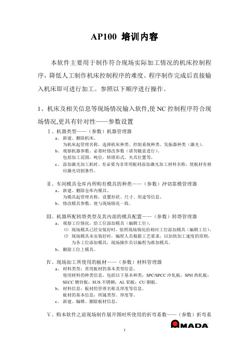
AP100 培训内容本软件主要用于制作符合现场实际加工情况的机床控制程序,降低人工制作机床控制程序的难度。
程序制作完成后直接输入机床即可进行加工。
参照以下顺序进行操作。
1、机床及相关信息等现场情况输入软件,使NC控制程序符合现场情况,更具有针对性——参数设置Ⅰ、机器类型——(参数)机器管理器a、新建、删除机床。
为机床起管理名称,选择机床种类、控制系统种类、发振器种类(激光)。
b、观察机器参数,必要时修改参数(请勿随意进行)。
包括加工范围,吨位,转塔形式、夹具位置等。
c、添加激光加工机时,有必要为非常用板材添加激光加工材料名称,使板材有相应激光切割条件。
Ⅱ、车间模具仓库内所购有模具的种类——(参数)冲切靠模管理器a、新建、删除仓库内模具。
为模具起管理名称,设置形状、尺寸、用途等信息。
b、修改模具参数,使与现场情况一致。
Ⅲ、机器所配转塔类型及其内部的模具配置——(参数)转塔管理器a、观察工位情况,给工位添加模具(编辑工位)。
⑴ 现场模具已经安装好时,依照现场情况给相应工位添加模具(编辑工位)。
⑵ 现场模具未安装好时,编程人员根据工艺要求,以加快加工速度的原则,为各工位添加模具,现场操作员以编程为准加模具。
b、删除工位上模具。
Ⅳ、现场加工所使用的板材——(参数)材料管理器a、材料类型:常用板材的基本类型信息。
使用材料的种类信息,包括以下基本种类:SPC/SPCC冷轧板;SPH热轧板;SECC镀锌板;SUS不锈钢;AL铝板;CU铜板。
b、材料信息:板材的管理名称及厚度等信息。
板材的基本信息:所属类型、厚度等。
c、新建、编辑、删除板材信息。
Ⅴ、购本软件之前现场制作展开图时所使用的折弯系数——(参数)折弯系数管理器。
a、本软件内置有展开系数模块,效果良好、推荐使用。
b、如果须使用现场原有折弯系数,可在此建立录入。
针对不同板材,建立不同折弯角度下的折扣系数。
2、待加工零件的图纸信息的建立——制作展开图Ⅰ、对来自其他软件的电子图纸的处理(.dwg .dxf .iges)。
APM-100光纤准备机中文翻译(原创)
APM-100光纤准备机中文翻译(原创)
预览说明:预览图片所展示的格式为文档的源格式展示,下载源文件没有水印,内容可编辑和复制
APM-100全自动光纤熔接准备机APM-100属于藤仓的“ARC Master”产品线系列
具有以下特性:
1.全自动工作,无需操作者技能要求
2.快速作业,低至18秒的剥线/清洁/切割操作
3.自动进行残渣收集和清洁
4.酒精循环系统允许延长重装的时间
5.钻石刀片提供持续稳定的切割质量
6.可靠剥线的方法,最小化对光纤的损害
注:藤仓新的“ARC Master”系列熔接机凝聚着一系列稳健的特性,带给客户在其他地方得不到的技术和可靠性。
对精度,可靠性以及持续熔接的需求,已经扩展到超出电信范围的新应用。
这些来自藤仓设计的完全新的“ARC Master”系列熔接机,已经发展到可以为不同种类的客户和市场提供终极的性能和灵活的应用。
以上标准套件见下图:
作业流程:1.放置光纤(需要光纤夹持器) 2.剥线,清洁和切割(操作:按下SET按钮开始执行.剥线,清洁和切割)。
3.完成。
AP100压力控制阀使用说明书
Instruction ManualPressure Control Valve (Relief Valve) AP100The intended use of a pressure control valve is to maintain a set pressure in part of a circuit by releasing pressure greater than the set pressure into the atmosphere.Validated according to ISO 13849, see section 2.1 Safety InstructionsThese safety instructions are intended to prevent hazardous situations and/or equipment damage. These instructions indicate the level of potential hazard with the labels of “Caution,” “Warning” or “Danger.” They are all important notes for safety and must be followed in addition to International Standards (ISO/IEC) *1), and other safety regulations. *1)ISO 4414: Pneumatic fluid power - - General rules relating to systems. ISO 4413: Hydraulic fluid power - - General rules relating to systems. IEC 60204-1: Safety of machinery - - Electrical equipment of machines. (Part 1: General requirements)ISO 10218-1: Manipulating industrial robots - - Safety. etc.This manual contains essential information for the protection of usersand others from possible injury and/or equipment damage.∙ Read this manual before using the product, to ensure correct handling, and read the manuals of related apparatus before use. ∙ Keep this manual in a safe place for future reference.∙ To ensure safety of personnel and equipment the safety instructions in this manual must be observed, along with other relevant safety practices.Warning∙ The compatibility of the product is the responsibility of the person who designs the equipment or decides its specifications. Since the product specified here is used under various operating conditions, its compatibility with specific equipment must be decided by the person who designs the equipment or decides its specifications based on necessary analysis and test results. The expected performance and safety assurance of the equipment will be the responsibility of the person who has determined its compatibility with the product. This person should also continuously review all specifications of the product referring to its latest catalogue information, with a view to giving due consideration to any possibility of equipment failure when configuring the equipment.∙ Only personnel with appropriate training should operate machinery and equipment.The product specified here may become unsafe if handled incorrectly.The assembly, operation and maintenance of machines or equipment including our products must be performed by an operator who is appropriately trained and experienced.∙ Do not service or attempt to remove product and machinery/equipment until safety is confirmed.1) The inspection and maintenance of machinery/equipment should only be performed after measures to prevent falling or runaway of the driven objects have been confirmed.2) When the product is to be removed, confirm that the safety measures as mentioned above are implemented and the power from any appropriate source is cut, and read and understand the specific product precautions of all relevant products carefully.3) Before machinery/equipment is restarted, take measures to prevent unexpected operation and malfunction.∙ Contact SMC beforehand and take special consideration of safety measures if the product is to be used in any of the following conditions.1) Conditions and environments outside of the given specifications, or use outdoors or in a place exposed to direct sunlight.2) Installation on equipment in conjunction with atomic energy, railways, air navigation, space, shipping, vehicles, military, medical treatment, combustions and recreation, or equipment in contact with food and beverages, emergency stop circuits, clutch and brake circuits in press applications, safety equipment or other applications unsuitable for the standard specification described in the product catalogue.3) An application which could have negative effects on people, property, or animals requiring special safety analysis outside the scope of ISO 13849 described in this document.4) Use in an interlock circuit, which requires the provision of double interlock for possible failure by using a mechanical protectivefunction, and periodical checks to confirm proper operation.∙ Always ensure compliance with relevant safety laws and standards.All electrical work must be carried out in a safe manner by a qualified person in compliance with applicable national regulations.Caution∙ The product is provided for use in manufacturing industries.The product herein described is basically provided for peaceful use in manufacturing industries.If considering using the product in other industries, consult SMC beforehand and exchange specifications or a contract if necessary. If anything is unclear, contact your nearest sales branch.2 SpecificationsNote 1) Under SMC test conditions. The B 10 figure is estimated from SMC life tests. The B 10D figure is derived from B 10 using the assumption in EN ISO 13849-1:2015 Annex C. Contact SMC for details. 2.2 Relief Flow CharacteristicsNote) The graph above shows the relief flow when the set pressure rises and falls from 0.1MPa.CautionSpecial products might have specifications different from those shown in this section. Contact SMC for specific drawings. These drawings will give the appropriate specification details and compliance with the safety principles of ISO 13849, if applicable.3 Installation3.1 MountingWarning∙ Do not install the product unless the safety instructions have been read and understood.∙ Ensure sufficient space for good access during maintenance activities.∙ Do not install the product unless the safety instructions have been read and understood. 3.2 Design / Selection∙ Confirm the specifications.Do not operate at pressures or temperature, etc., beyond the range of specifications, as this can cause damage or malfunction. We do not guarantee against any damage if the product is used outside of the specification range.∙ Do not use this product for caisson shielding, breathing, medical use, medicine that is injected by humans, or for blowing air on food products.The air preparation equipment has been designed exclusively for industrial compressed air, and it should not be used for any other purpose. Due to unavoidable circumstances, if it must be used for other purposes, make sure to follow safety measures and contact SMC beforehand.∙ Do not use this product on board a vehicle or a vessel.This product must not be installed and used on board a conveyance such as a vehicle or vessel, since it may become damaged due to vibrations. If it must be used in such a manner due to unavoidable circumstances, please contact SMC beforehand.3 Installation - continued∙ Do not disassemble the product or make any modifications, including additional machining.It may cause human injury and/or an accident.Caution∙ Do not use with low air pressure (blower).The air preparation equipment, which operates at a specific minimum operating pressure in accordance with the equipment to be used, is designed to be used exclusively with compressed air. Using it below the minimum operating pressure could lower its performance or cause malfunction. If it must be used under such conditions due to unavoidable circumstances, please contact SMC beforehand. 3.3 EnvironmentWarning∙ Do not use in an environment where corrosive gases, dust, chemicals, salt water or steam are present. ∙ Do not use in an explosive atmosphere.∙ Do not expose to direct sunlight or in a location exposed to radiant heat. Use a suitable protective cover and ensure good ventilation is used.∙ Do not install in a location subject to vibration or impact. Check the product specifications. 3.4 PipingCaution∙ Before piping make sure to clean up chips, cutting oil, dust, dirt, scale inside the piping etc. by air-flashing prior to connection.∙ When installing piping or fittings, ensure sealant material does not enter inside the port. When using seal tape, leave 1 thread exposed on the end of the pipe/fitting.Warning∙ Hold the female thread side and tighten to the recommended torque when screwing in the piping material.Insufficient tightening torque may cause loosening or defective sealing. Over-tightening torque may damage the thread etc. If it is tightened without holding the female thread side, excessive force will be directly applied to the piping bracket resulting in a product failure. ∙ Verify the IN and OUT sides.When connecting the piping, avoid interchanging the IN and the OUT sides. 3.5 LubricationCaution∙ SMC products have been lubricated for life at manufacture, and do not require lubrication in service.∙ If a lubricant is used in the system, use turbine oil Class 1 (no additive), ISO VG32. Once lubricant is used in the system, lubrication must be continued because the original lubricant applied during manufacturing will be washed away. 3.6 Air SupplyCaution∙ Do not use compressed air that contains chemicals, organic solvents, or corrosive gases.ORIGINAL INSTRUCTIONSSet pressure (MPa)R e l i e f f l o w {L /m i n (A N R )}AP100-024.1 Adjusting the set pressure∙ Rotate adjusting handle clockwise to increase pressure on the outlet port, and anti-clockwise to decrease it.∙ Adjustment and manipulation of the handle should be done manually. ∙ Once the pressure is set to the required value, fasten the lock-nut. This helps prevent fluctuation of the adjusted pressure due to vibration.7.1 General MaintenanceCaution∙ Not following proper maintenance procedures could cause the product to malfunction and lead to equipment damage.∙ If handled improperly, compressed air can be dangerous. Maintenance of pneumatic systems should be performed only by qualified personnel.∙ Before performing maintenance, turn off the power supply and be sure to cut off the supply pressure. Confirm that the air is released to atmosphere.∙ After installation and maintenance, apply operating pressure and power to the equipment and perform appropriate functional and leakage tests to make sure the equipment is installed correctly.∙ If any electrical connections are disturbed during maintenance, ensure they are reconnected correctly and safety checks are carried out as required to ensure continued compliance with applicable national regulations.∙ Do not make any modification to the product.∙ Do not disassemble the product, unless required by installation or maintenance instructions.Warning∙ If an abnormal condition occurs, turn off the power supply and stop the flow of compressed air.If an abnormal condition occurs, such as smoke, foul smell, or noise, immediately turn off the power supply, stop the glow of compressed air and set the pressure of the compressed air to zero because there is a possible risk of electrical shock or fire. .∙ Do not use this product on board a vehicle or a vessel.This product must not be installed and used on board a conveyance such as a vehicle or vessel, since it may become damaged due to vibrations. If it must be used in such a manner due to unavoidable circumstances, please contact SMC beforehand.8 Limitations of Use8.1 Limited warranty and Disclaimer/Compliance Requirements ∙ The product used is subject to the fol lowing “Limited warranty and Disclaimer” and “Compliance Requirements”. Read and accept them before using the product .∙ Limited warranty and Disclaimer1) The warranty period of the product is 1 year in service or 1.5 years after the product is delivered, whichever is first (1). Also, the product may have specified durability, running distance or replacement parts. Please consult your nearest sales branch.2) For any failure or damage reported within the warranty period which is clearly our responsibility, a replacement product or necessary parts will be provided.This limited warranty applies only to our product independently, and not to any other damage incurred due to the failure of the product. 3) Prior to using SMC products, please read and understand the warranty terms and disclaimers noted in the specified catalogue for the particular products. (1)Vacuum pads are excluded from this 1 year warranty.A vacuum pad is a consumable part, so it is warranted for a year after it is delivered. Also, even within the warranty period, the wear of a product due to the use of the vacuum pad or failure due to the deterioration of rubber material are not covered by the limited warranty.∙ Compliance Requirements1) The use of SMC products with production equipment for the manufacture of weapons of mass destruction (WMD) or any other weapon is strictly prohibited.2) The exports of SMC products or technology from one country to another are governed by the relevant security laws and regulations of the countries involved in the transaction. Prior to the shipment of a SMC product to another country, assure that all local rules governing that export are known and followed.Caution∙ SMC products are not intended for use as instruments for legal metrology.Measurement instruments that SMC manufactures or sells have not been qualified by type approval tests relevant to the metrology (measurement) laws of each country.Therefore, SMC products cannot be used for business or certification ordained by the metrology (measurement) laws of each country.Danger∙ Do not use this product as a safety valve.Definition of safety valves (JIS). Valves used for ensuring pressure capacity and piping safety.9 ContactsKeynes, Buckinghamshire MK8 0AN, United KingdomURL : http// (Global) http// (Europe) 'SMC Corporation, Akihabara UDX15F, 4-14-1, Sotokanda, Chiyoda-ku, Tokyo 101 0021Specifications are subject to change without prior notice from the manufacturer. © 2017 SMC Corporation All Rights Reserved. Template DKP50047-F-085EAP100 – 01 –Symbol Type Nil Rc N NPTF GSymbol Size 01 1/8 02 1/4 Symbol Description Nil – B With bracket Symbol Specifications –Set pressure range 0.02 to 0.2 MPaPressure control valve Thread type Connection thread Accessory Special specifications IN OUTPanel cut dimensions¤: Validated according to ISO13849-2。
AMADA数控冲床编程软件AP100安装方法和管理
AMADA数控冲床编程软件AP100安装方法和管理
By huang - Posted on February 16th, 2008
这个软件不大,但是安装麻烦。
现在用的是AP100 V er3.02sp1版本。
必须安装在windows2000系统上.
新版本ver3.4可以安装在windows xp上并且改成了使用dongle的加密方式方式方便了更换电脑硬件.
1.电脑硬盘分3个区, c盘放系统,d盘房数据,e盘放程序和备份.
(目前认为比较科学的分区方法)
2. 安装windows2000 pro并打完所有补丁
(ap100要求是win2ksp2,但考虑到安全问题并测试过sp4rollup1均能正常工作)
3. 更改计算机名
这一步很重要,必须在安装ap100前改开始编程后计算机名就不能改了,不然马上出错.
如果是格式化重新安装或替换某个原来的编程电脑需要导入数据库的,则计算机名必须和原数据库计算机名一样.
4. 配置好网卡IP, 安装net BEUI 网络协议
可以使用DHCP但是必须装Net BEUI
5. 开始安装AP100. 具体步骤见安装光盘.
安装注意事项: 必须仔细看安装说明,有时候目录下会有install.exe,setup.exe等很多exe文件必须执行说明书里指定的那个不能看错.
安装完每个程序即使没有提示也最好重新启动一下,.
安装SQL补丁时可以使用最新的sp4 而不是说明里的sp3. 能正常工作.。
AP100编程教程
AP100编程教程AP100编程完整教程⽬录⼀、程序⽂件建⽴⼆、编程及菜单栏命令应⽤实例三、排版四、模具登录五、M代码设定及调整六、常见异常排除⼀、程序⽂件建⽴双击“AP100Startup”。
单击数据管理依次单击左上⾓新建→⽂件夹输⼊程序⽂件夹名称后点击登记点关闭及电脑操作视窗关闭键完成⽂件建⽴。
⼆、CAD图档导⼊返回AP100主菜单,单击展开图制作点击左上⾓⽂件→从DWG导⼊到(K)打开要编程的图纸⽬标⽂件夹选择要编程⽂件,点打开点击“是”点击“确定”点击“是”点击“确定”点击“确定”点击删除键,框选⽆⽤⽂件,按⿏标右键,选完成。
根据加⼯要求将图档旋转或反向移动,以达到符合机床加⼯的最佳要求〖移动/复制(图⽰1)→旋转移动(图⽰2)→选取两点确定选装⽅向(图⽰3/4)→输⼊旋转⾓度(图⽰5)→按Enter键完成旋转〗点击⼜上⾓CAM选择程序要保存的⽂件夹,然后点保存选择板材材质及厚度→设置板材⼤⼩→设置板材安全距离(默认值X:20,Y80)→点“确定”点击“AUTO”→“确定”进⾏⾃动编程点击删除键,选择并删除⾃动编程中不符合最优加⼯的⼑路(原则:能⽤⼀⼑冲出的效果不⽤两⼑冲,外边冲切尽可能选⽤最长,宽度5MM的⼑具)。
常⽤⼯具栏命令⼿动排⼑实例:a.选定合适模具(合适⼤⼩及⽅向)→b.点击⼿动排⼑命令→c.点取需要冲切线起点与终点→d.设置模具起点、终点与需冲切起点、终点距离→e.单击需冲切边外侧→f.点击应⽤、关闭模具中⼼点捕捉排⼑实例:a.选定合适模具(合适⼤⼩及⽅向)→b.点击模具中⼼点捕捉排⼑命令→c.将模具放置到需要冲切边外缘→d.点击关闭移动实例:a.单击移动、复制命令→b.点击移动→c.单击需移动模具→d.点击结束指令→选取模具移动起点(图⽰5)→选取模具移动终点(图⽰6,⽩⾊捕捉点)复制实例:a.单击移动、复制命令→b.点击复制→c.单击需复制模具→d.点击结束指令→选取模具复制参考点(图⽰5)→选取需粘贴冲切位置参考点(图⽰6,⽩⾊捕捉点)⾃动线排⼑实例:a.选定合适模具(合适⼤⼩及⽅向)→b.单击⾃动线排⼑命令c.设置补偿值(内侧冲切补偿值为0,切边冲切补偿值为1)→d.将⿏标指针移动⾄需冲切线内侧并单击点排⼑命令实例:a.点击点排⼑命令→b.选取适合冲切⼑具→c.点击模具拾取点→d.点击需冲切位置拾取点拉伸命令实例:a.点击拉伸命令→b.选取需拉伸模具端点→c.选取需拉伸位置→d.单击⿏标确认。
- 1、下载文档前请自行甄别文档内容的完整性,平台不提供额外的编辑、内容补充、找答案等附加服务。
- 2、"仅部分预览"的文档,不可在线预览部分如存在完整性等问题,可反馈申请退款(可完整预览的文档不适用该条件!)。
- 3、如文档侵犯您的权益,请联系客服反馈,我们会尽快为您处理(人工客服工作时间:9:00-18:30)。
2.反应堆冷却剂系统(15)
37
2.反应堆冷却剂系统(16)
主泵数量 主泵类型 主泵材料 主泵额定流量(m3/hr) 主泵额定压头(m) 设计压力(MPa.g) 设计温度(C) 最大持续设备冷却水进口温度(C) 泵出口管嘴内径(mm) 泵吸入管嘴内径(mm) 4 屏蔽泵 不锈钢 17876 111 17.13 343.3 35 559 660
AP1000总体介绍
2011年5月
内容概况
设计概况
核岛主要系统设备
常规岛主要系统设备
电气主要系统设备
培训目标
了解系统主要功能和工艺流程; 熟悉主要设备结构、作用和运行方式; 了本系统和其它系统的相互关系; 记住系统和设备的主要技术参数。
3
一、设计概况
4
一、设计概况(1)
AP1000是西屋公司在AP600的基础上开发的非 能动先进压水堆,于2005年12月获得NRC的“ 设计证书”。 AP1000与传统成熟的压水堆核电厂技术最大 的不同,就是其安全系统采用了“非能动” 技术。 AP1000为单堆布置的两环路机组,电功率约 1250MWe,设计寿命60年,主泵采用屏蔽泵 ,安全壳为双层结构,外层为预应力混凝土 ,内层为钢板结构。
26
2.反应堆冷却剂系统(5)
27
2.反应堆冷却剂系统(6)
蒸汽发生器主要技术特点 – 蒸汽发生器的U型传热管采用三角形排列; – 蒸汽发生器在全挥发处理二次侧水化学条件下运行; – 管板上的传热管采用全深度液压膨胀,最大限度地防止二 回路水进入传热管与管板之间的缝隙; – U型传热管采用镍一铬一铁合金690热处理管; – 采用三叶状孔(梅花孔)支撑板,改进了防振条工艺; – 采用一体化的汽水分离器; – 采用椭圆形的一次侧下腔室,便于机器人工具进出和维护 保养。 – 蒸汽发生器下封头直接与两台主泵的壳体相连接。
50
6.厂用水系统(1)
系统功能:
在各种运行模式下带走设备冷却水系统的热 量
51
6.厂用水系统(2)
52
6.厂用水系统(3)
表 3.6.1 不同运行模式下厂用水的额定流量和热负荷 SWS 泵 正 常投入台数 1 2 2 2 CCS 泵 和热交换 器 正常运行 (满负荷) 电站冷却 换料 (全堆芯卸出) 电站启动 支持安全停堆 和乏燃料冷却 的 最 小 量 (SWS 系统供 水 温 度 90.5oF (32.5oC) 1 2 2 2 额定流量 10,800 gpm (2453 m3/hr) 21,600 gpm (4906 m3/hr) 21,600 gpm (4906 m3/hr) 21,600 gpm (4906 m3/hr) 热传输 90.4 x10⁶ Btu/hr (26.5 MW) 303 x106 Btu/hr (88.7 MW) 73.9 x10⁶ Btu/hr (21.6 MW) 76.1 x10⁶ Btu/hr (22.3 MW)
30
2.反应堆冷却剂系统(9)
图3.2.4 稳压器 31
2.反应堆冷却剂系统(10)
稳压器主要功能: 压力控制 超压保护 容积补偿 排除不凝性气体
32
2.反应堆冷却剂系统(11)
33
2.反应堆冷却剂系统(12)
34
2.反应堆冷却剂系统(13)
35
2.反应堆冷却剂系统(14)
28
2.反应堆冷却剂系统(7)
29
2.反应堆冷却剂系统(8)
蒸汽发生器设计参数: 每台蒸汽发生器的管子数;10,025根 蒸汽发生器总高:22.5m 每台蒸汽发生器的蒸汽流量:3400T/h 总的蒸汽流量:6795T/h 给水温度:227℃ 蒸汽发生器出口压力:5.612MPa 设计压力:8.274 MPa 设计温度:316℃
58
7.非能动堆芯冷却系统(6)
59
7.非能动堆芯冷却系统(3)
非能动堆芯冷却系统设计参数: 1.补给水箱2只 2.非能动热交换器1个 ~设计压力:17.1MPa ~设计压力:17.1MPa ~设计温度:343℃ ~设计温度:343℃ ~总容积:70.8m3×2 ~热交换面积:476m2 ~硼浓度:3500PPm 3.安注箱2只 4.安全壳内置换料水箱1只 ~正常运行压力:4.8MPa ~总水容积:2131 m3 ~总容积:56.6 m3×2 ~硼浓度:2700PPm ~正常运行水容积:48.1 m3 ~正常运行气容积:8.5 m3
47
5.设备冷却水系统(1)
系统功能:
为各类非安全设备提供冷却水,冷却各种核 岛热交换器、泵等设备;
经过由厂用水系统冷却的热交换器将热负荷 传递至最终热阱--海水; 在核岛热交换器和海水之间形成屏障,防止 放射性流体不可控制地释放到海水中,避免 由于海水直接冷却而产生腐蚀污垢等问题。
48
5.设备冷却水系统(2)
49
5.设备冷却水系统(3)
表 3.5.1 设备冷却水系统(CCS)主要参数 设备名称 设备冷却水泵 设计流量 设计扬程 设备冷却水热交换器 设计能力 设计流量 设冷水侧 8.17 MW/C 2225.82 m3/h 2225.82 m3/h 77.72 m 厂用水侧 8.17 MW/C 2680 m3/h 参数
38
2.反应堆冷却剂系统(17)
热段
39
2.反应堆冷却剂系统(18)
冷 段
40
3.化学和容积控制系统(1)
基本功能:
容积控制,通过上充和下泄功能维持稳压器 水位,保持一回路水容积。
反应性控制,调节冷却剂硼浓度,补偿反应 堆缓慢的反应性变化。 化学控制,控制反应堆冷却剂的pH值、氧含 量和其他气体含量,防止腐蚀,裂变气体积 聚和爆炸;除去腐蚀和裂变产物,降低冷却 剂的放射性水平。
5
一、设计概况(2)
AP1000的主要设计特点有: 主回路系统和设备设计采用成熟电站设计 简化的非能动设计提高了安全性和经济性 仪控系统和主控室设计 AP1000仪控系统采用 成熟的数字化技术设计 建造中大量采用模块化建造技术 AP1000在建 造中大量采用模块化建造技术
6
一、设计概况(3)
13
1.反应堆(5)
14
1.反应堆(6)
15
1.反应堆(7)
燃料组件主要设计参数: 燃料元件;157盒 核裂变原料:铀235,浓集度2.35%-4.8% 锆合金管内充氦密封成外径0.95㎝含有434块 芯块的单根铀棒 把铀棒排列成17x17正方阵构成燃料组件,每 个燃料组件有264根燃料棒,24根控制棒导管, 以及1根中央测量管。总重115kg。 组件设计燃耗值60000Mwd/t,燃料单棒为 62000Mwd/t
系统分类: 分核岛、常规岛、BOP、电气、仪控五大部分 共118个系统 系统清单见附件
7
一、设计概况(4)
主要设计参数:
AP1000发电机的上网电为1090MKW
NNNS热功率为3415MKW 反应堆的换料周期为18个月 100%功率甩负荷到厂用电,不仃堆、仃机 设计寿期为60年 RCS设计压力:17.1MPa RCS设计温度:343℃(360℃) 正常运行压力:15.4 Mpa
16
1.反应堆(8)
17
1.反应堆(9)
控制棒设计参数: 控制捧(黑捧): —53束,每束24根 —吸收材料:银-铟-镉合金封包在不锈钢管 内 灰棒: —16束,每束24根 —吸收材料: 12根银-铟-镉合金,12根为不 锈钢材料
18
1.反应堆(10)
19
1.反应堆(11)
20
1.反应堆(12)
41
3.化学和容积控制系统(2)
42
3.化学和容积控制系统(3)
主要的设计参数 正常硼化流量:22.71m3/h 正常稀释流量:22.71m3/h 正常下泄净化流量:22.71m3/h 通过离子交换柱的最高允许温度:54.4℃ 硼酸贮存箱的硼浓度:4375PPm 反应堆冷却剂过虑器(A.B)精度:0.25μm 一台上充泵最补水流量:30.66m3/h 二台上充泵最补水流量:39.75m3/h
43
4.正常余热排出系统(1)
主要功能: 停堆冷却:在停堆冷却的第二阶段,将一回路从 176.7℃降到51.7℃,并维持此温度稳定。 停堆净化:在换料工况下,与化容系统配合,余热 排出泵代替主泵作为净化流的强制循环驱动压头,对 一回路和换料水池的水体进行净化,以保持RCS和换料 水池的水质指标。 冷却安全壳内置换料水箱(IRWST)。
热段温度:321 ℃ ~冷段温度:281 ℃
8
二、核岛主要系统及设备
9
1.反应堆(1)
10
1.反应堆(2)
反应堆主要包括以下部件: —堆芯 —堆内构件 —压力容器 —控制棒驱动机构 —一体化上封头 —堆芯仪表系统等
11
1.反应堆(3)
12
1.反应堆(4)
反应堆堆芯的主要设计参数: 压力壳内径;4.039m 压力壳总高:12.2m 堆芯燃料组件数;157合 燃料活性长度;4.27m 燃料组件排列;17 x 17 控制组件数;53 灰棒组件数;16
1
1
10,300 gpm ( 2339 m3/hr)
182 x106 Btu/hr ( 53.3 MW)
53
7.非能动堆芯冷却系统(1)
系统功能: RCS应急补水和硼化 应急堆芯余热导出 事故后安全壳内pH值控制 过程参数监测
54
7.非能动堆芯冷却系统(2)
55
7.非能动堆芯冷却系统(3)
60
8.非能动安全壳冷却系统(1)
系统功能: 安全壳内热量导出 过程监测 补充乏燃料水池水装量 消防水补充