快意CTRL20调试手册
快意电梯CTRL50(60)调试工艺1

一、 总则:本守则适用于本公司CTRL50、CTRL60控制系统现场调试。
二、 调试步骤1. 调试前的准备工作1.1现场整洁:清理机房、井道、底坑、轿厢、轿顶、层门等处的杂物,保持现场卫生整洁。
1. 2安装接线进行复查,特别是主回路的动力线、轿门门锁、厅门门锁回路、极限开关、限位开关、光电编码器和安全回路装置的连接线。
1. 3安全检查:对安全回路所有开关和门锁回路开关进行检查,每个开关都应能可靠使相应回路供电电源断开。
1.4绝缘检查:用500V兆欧表测量:动力电路和电气安全装置电路≥0.5MΩ,其它电路≥0.25MΩ,电路电压在25V 以下除外。
1. 5检查电梯的机械和电气设备安装是否已具备调试运转条件。
1. 6查三相五线制的零线是否接到控制柜上的N端子,接地线应可靠接地。
1.7电气和机械各部分已进行必要的单体检查、试验和调试。
1. 8较厢沿井道全程运动无卡阻、碰撞、安全距离应符合有关规定。
1. 9调试人员在调试过程中务必认真负责,细致周到,严格做好安全工作。
1. 10调试所需仪器(一般正常情况下)万用表 钳形表 兆欧表(500V/1000V)直尺 常用电工工具1.11电梯已经过电机参数自学习,并且已根据《CTRL50(60)配*变频器参数设定表》将所有参数输入到变频器中去。
(*表示可选,根据不同变频器有不同设定表)2. 检修状态的调试2.1在没有进行过层高位置的自动写入之前,楼层指示灯的显示值不表示电梯的实际位置。
2.2合上总电源,测量R、S、T之间的电压值,且满足以下要求:R-S ~380V±7%S-T ~380V±7%R-T ~380V±7%2.3检查相序继电器是否工作正常,如:相序继电器故障灯亮,请检查三相交流电源是否缺相及错相。
2.4电梯是否在检修状态,如在检修状态时CTRL50输入点X20暗,CTRL60输入点X17暗。
2. 5检查所有的安全触点、开关,在正常状态下JY接触器吸合,并逐个人为动作,都应能使JY接触器释放。
快意电梯CTRL20调试工艺1
一、总则:本守则适用于本公司CTRL20-V100和CTRL20-V101控制系统现场调试。
二、调试前的准备工作2.1调试人员必须看懂电梯电气原理图及全部调试资料。
2.2做好现场(机房、井道、底坑、轿厢、轿顶、层门等)的整洁工作。
2.3安装接线结束后,必须进行复查,特别是主回路的动力线、轿门门锁、厅门门锁回路、极限开关、限位开关、光电编码器和安全回路装置的连接线。
2.4电梯的机械和电气设备安装已具备运转条件。
2.5复查三相五线制的地线是否接到控制柜上的接地铜排上。
2.6电气和机械各部分已进行必要的单体检查、试验和调试。
2.7轿厢沿井道全程运动无卡阻、碰撞、安全距离应符合有关规定。
2.8调试人员在调试过程中务必认真负责,细致周到,严格做好安全工作。
2.9调试所需仪器(一般正常情况下)万用表钳形表直尺常用电工工具2.10电梯已经过电机参数自学习,并且已根据《变频器(V101)参数表》或《变频器(V100)参数表》将所有参数输入到变频器中去了。
2.11在进行楼层高度自学习之前,应先按照《主控板参数表》对“开放功能选择”、“基本设定”、“时间参数”、距离参数“等进行设定。
2.12主控板“码盘转换因数”的设定(※修改后必须重新进行楼高自学习)此参数为最重要的速度与高度换算依据,应准确计算设定。
此参数=电梯行驶1米时旋转编码器所经历的刻度数目=行驶某特定距离时旋转编码器所经历的刻度数目÷该特定距离的米数=(编码器脉冲数×减速机比)÷(牵引轮直径(米)×3.14159)当编码器信号是采用变频器分频以后的信号时(最好如此),编码器刻度应采用分频以后的数值。
例如:某曳引机,编码器为8192脉冲/转,采用1分频,2:1的绕绳方式,牵引轮直径0.4米,则此参数=(8192÷1×2)÷(0.4×3.14159)=13040根据我司电梯各参数值进行计算:同步电机时:“码盘转换因数”=13044,异步电机时:“码盘转换因数”=2000(分频比F1-06=8),三、检修状态的调试3.1合上总电源,测量R、S、T之间的电压值,且满足以下要求:R-S ~380V±7% S-T ~380V±7% R-T ~380V±7%CTRL20系统设计Design 图名Title 调试工艺守则3.2检查相序继电器是否工作正常,如:相序继电器故障灯亮,请检查三相交流电源是否缺相及错相。
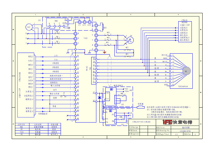
快意电梯20系统变频器的接线图
1
黑
DC0V
2
红
DC+5V
3
C
蓝
A+
4
蓝/黑
A-
5
绿
B+
6
PG
绿/黑
B-
7
棕色
U+
8
棕/黑
U-
9
灰
V+ 10
灰/黑
V- 11
白
W+ 12
B
白/黑
W- 13
TS5246N16*
N23 8D1
1(+) 2(-)
N24* 6 61 JMS 62 5
技术说明(此图只适用于型号为IFE的变频器): 注1.该功能为增选(能量回馈)功能。
运行 输出公共端 JY
故障 43 44
零速 黄黑色15
棕黑色12
变频器备妥
A 元件代号 HKQ DY V101 PG
元件名称 能量回馈器 曳引机 变频器 编码器
1
安装位置 控)1 (+)2 B1
B2 R
U S V101
V T
W
E 12
S1
IG S2
IP
S3
A+
MC1 51 52 71 72
传感器
淡绿黑色23 粉红黑色25
DC+12V
1
C
黑
DC0V
2
红
DC+5V
3
蓝
A+
4
蓝/黑
A-
5
绿
B+
6
PG
绿/黑
B-
7
黄
Z+
8
黄/黑
快意电梯原理图CTRL20-V101小机房

CTRL20-V101(小机房) 现场施工文件目录序 号 图 号 图 纸 名 称 版本号备注 一、敷线图及各接线图 1 C21X0030P01 系统敷线图(机房) B增加曳引断绳开关2 C21X0030P02 系统敷线图(轿厢) B 替换A 版3 C21X0030P03 系统敷线图(井道) A4 C21X0030P04 控制柜外围接线图 B 增加曳引断绳开关5 C21X0030P05 机房接线图 B 替换A 版6 C21X0030P06 轿顶检修箱外围接线图 B 替换A 版7 C21X0030P07 井道电缆接线图 B 替换A 版8 C21X0030P08 井道换速开关接线图 A 9 C21X0030P09 门锁分支电缆及安全回路接线图 A 10 C21X0030P10 外呼通讯 A 11 C21X0030P11 底坑照明及警铃接线图 A 12 C21X0030P12 平层感应接线图 A二、井道开关及电缆安装图 1 C21X0031P01 井道开关安装图 A 2 C21X0031P02 井道电缆安装示意图A12345678ABCDDCBA设计Design审核Check 批准Approve图名Title 图号Drawing No.页码Page/Total版本Ver.MOVING & SERVING机房开关盒M03M01外电网三相五线制电源用户电源箱R S TPER S T 501ZK01ZK02ZK03TK01TK02TK0317位13位11位TK089位ZK08C01井道照明端子端子主机编码器屏蔽电缆抱闸M07M02U V W02 99变频器U V W控制柜W03M06CTRL20-V101(小机房)系统敷线图(机房)C21X0030P011/12B132456789X1P1见图C21X0030P02W01502 601 602 0299+N -L M02R ARDR S T ZK06TK0611位M10TK0421位ZK04U V WM02主电缆配置表电梯速度载重量630kg以下750-800kg800-1000kg 1500-2000kg 1.0RVV 4×6mm m/s 电缆规格2RVV 4×6mm 2RVV 4×6mm2RVV 4×10mm 21.5-1.75RVV 4×6mm2RVV 4×10mm 2RVV 4×10mm2RVV 4×16mm2载荷控制仪传感器M11PG-X2卡V101主控板M12TK055位ZK05见图C21X0030P03KCF KCF1KCFKCF1KCF 消防中心M09其他设备共用电源。
SHIMADZU AOC-20 Clarity Control Module 说明书

SHIMADZU AOC-20Clarity Control Module ENGCode/Rev.:M090/90BDate:10/2/2023DataApex Ltd. Phone:+420251013400Petrzilkova2583/13 ********************15800Prague5 The Czech RepublicClarity®,DataApex®and®are trademarks of DataApex Ltd.Microsoft®and Windows TM aretrademarks of Microsoft Corporation.DataApex reserves the right to make changes to manuals without prior notice.Updated manuals can be downloaded from .Author:MPContents1Shimadzu AOC-20i/s/d Control module1 2Requirements2 3Installation Procedure33.1Autosampler Setup-communication33.1.1Connections43.2Clarity Configuration54Using the control module74.1Hardware Configuration dialog74.2Method Setup-AS84.3Shimadzu AOC-20i/s Setup105Sequence12 6Troubleshooting13To facilitate the orientation in the Shimadzu AOC-20manual and Clarity chromatography station, different fonts are used throughout the manual.Meanings of these fonts are:Open File(italics)describes the commands and names of fields in Clarity,parameters that can be entered into them or a window or dialog name.WORK1(capitals)indicates the name of the file and/or directory.ACTIVE(capital italics)marks the state of the station or its part.Chromatogram(blue underlined)marks clickable links referring to related chapters.The bold text is sometimes also used for important parts of the text and the name of the Clarity station.Moreover,some sections are written in format other than normal text.These sections are formatted as follows:Note:Notifies the reader of relevant information.Caution:Warns the user of possibly dangerous or very important information.▌Marks the problem statement or trouble question.Description:Presents more detailed information on the problem,describes its causes, etc.Solution:Marks the response to the question,presents a procedure how to remove it.Shimadzu AOC-201Shimadzu AOC-20i/s/d Control module 1Shimadzu AOC-20i/s/d Control module This manual describes the setting of the Shimadzu AOC-20i/s/d autosamplers.The control module enables direct control of the instrument over serial line.Fig.1:AOC-20iDirect control means that the autosampler can be completely controlled from the Clarity environment.Instrument method controlling for example the vials and further device specific functions(e.g.washing)will be saved in the measured chromatograms.Shimadzu AOC-202Requirements2Requirementsl Clarity Installation with AS Control module(p/n A26).l Free serial port in the PC(fast-16550UART).Note:Modern computers usually have only1(if any)serial(COM)port installed.To use more devices requiring the port,the MultiCOM adapter(p/n MC01)is available.l Serial cross DB9F-DB9F cable(p/n SK01).Note:Cables are not part of Clarity Control Module.It is strongly recommended to order required cables together with the Control Module.Caution:We have experienced power sources(controller boards)with DB9F connector on the back instead of normal DB9M connector.In that case,serial cross DB9M-DB9F cable is necessary.Contact our support on******************to consultthe correct wiring.3Installation Procedure3.1Autosampler Setup-communicationThe autosampler communicates with PC using the RS232-compliant serial cross DB9F-DB9F cable.Fig.2:Serial cross DB9F-DB9F cableThe RS-232cable is plugged in to the autosampler controller board(not the tower) present at the back side of the GC,replacing the cable connecting it to the GC in default setup,as displayed in the Fig.3on pg.3.Fig.3:Shimadzu AOC-20controller board connections3.1.1ConnectionsBesides the serial RS-232cable,the connections must be made between the autosampler Start OUT/Ready IN connector and the appropriate connectors on the GC to allow proper synchronization between the AS and GC.l The Clarity Start(IN)input must be connected to the GC Start Out connector.l The Clarity Ready(OUT)digital output is not used,the commands are transmitted over the serial line.Refer to Shimadzu manual for description of cables supplied with the autosampler.When autosampler has to be used with Shimadzu201x series GCs( 2010,2014, 2014C,2014APC/AFC),it is necessary to connect it to the PC via separate serial line.The controller box is build in the GC2010/2014case,but to use the control from Clarity,the short serial cable from the GC to the controller box needs to be disconnected and replaced by a serial cable to the PC.3.2Clarity ConfigurationFig.4:How to add Shimadzu AOC-20l Start the Clarity station by clicking on the icon on the desktop.l Invoke the System Configuration dialog accessible from the Clarity window using the mand.l Press the Add button①(see Fig.4on pg.5.)to invoke the Available Control Modules dialog.l You can specify the searching filter②to simplify the finding of the driver.l Select the AOC-20sampler and press the Add③button.The Shimadzu AOC-20i/s Setup dialog will appear.Fig.5:Shimadzu AOC-20i/s Setupl Select the correct Port,Baud Rate,Parity and Stop bit settings for the autosampler.Then press the Connect button.If the communication is correct,the status of the autosampler will appear in the Connection row.Note:The Shimadzu AOC-20i/s Setup dialog is more closely described in the chapter "Shimadzu AOC-20i/s Setup"on pg.10.The AOC-20autosampler item will appear in the Setup Control Modules list of the System Configuration dialog.l Drag and drop the AOC-20icon from the Setup Control Modules④list on the left side of the System Configuration dialog to the desired Instrument⑤tab on the right side⑥(or use the button⑦to do so).4Using the control moduleNew Method Setup-AS tab appears in the Method Setup dialog,enabling the setting of the AS control method.The From AS and To AS buttons serve for transfer of methods from and to autosampler.Caution:If you have injection methods already established in the sampler,it is advisable to download them to Clarity using the From AS button and save them as a Claritymethod.The AS Status button displays the Hardware Configuration dialog.4.1Hardware Configuration dialogFig.6:Hardware ConfigurationThis dialog displays automatically detected communication port.4.2Method Setup-ASFig.7:Method Setup-AS-Parameters Dwell timeWaiting time after sample injection.Valid range:0-99.9sRinse with sampleSample washing times of the syringe before injection.Valid range:0-99Rinse with solventSolvent washing times of the syringe after injection.Valid range:0-99Viscosity timeWaiting time of the plunger after sample suction.Valid range:0-99.9sPump syringeNumber of pumpings.Valid range:0-99Plunger injection speedInjection speed of the plunger.Plunger suction speedPlunger suction speed at sample suction.Injection typeInjection type.Standard-sample+(air)Solvent flush-solvent+air+sample+(air)Solvent flush w/o air-solvent+sample+(air)Standard internal-solvent+air+standard sample+air+sample+(air)Standard internal w/o air-solvent+standard sample+sample+(air)Syringe injection speedInjection speed of the syringe.Select SolventSelects the appropriate solvent for solvent wash in case there are three solvent vials on the sampler rack.It is necessary to enable this option in the Shimadzu AOC-20i/s Setup dialog using the Use three solvents checkbox.Air SuctionCheck if you want autosampler to suck air into the needle after sample suction.This can help prevent premature evaporation of part of the sample,when the needle is warmed-up.4.3Shimadzu AOC-20i/s SetupThe Shimadzu AOC-20i/s Setup dialog sets the fundamental options of the control module.Note:It is accessible from the System Configuration dialog by doubleclicking the Shimadzu AOC-20i/s item.Fig.8:Shimadzu AOC-20i/s SetupPortCOM Port used for communication between the hardware and the PC.Baud Rate,Parity,Stop BitCommunication parameters.Those parameters should be set according to the actual communication parameters set in the autosampler(use the Function key to check/modify them)Default values:Baud rate:2400(F80=2)Parity:none(F81=0)Stop bits:2(F82=1)Note:The changes made on the sampler are active only after power restart.ConnectButton which tests communication with auto-injector hardware and detects if auto-sampler hardware is present.First fill in the COM Port,Baud rate,Parity,Stop bit fields and check AOC17mode if you need AOC-17compatible mode,then press the Connect button.Now connection is tested and auto-sampler is detected for established connection.Connection state is shown in the Connection field.If connection fails then message box appears and you are asked to check some parameters on the hardware.ConnectionConnection status.Sampler nameAssigns name to the sampler,under which it appears in configuration,method setup,reports,etc.ModelDefines the model of the AOC-20sampler.Vial sizeDefines the type of the vials used on the sampler.Syringe typeDefines the type of the syringe.AOC-17modeSetting this checkbox enables AOC-17compatible mode.To use the AOC20in this mode,set the functions F84=1(default is F84=0).Note:Regardless of mode used,the Channel1Protocol parameter must be zero (F83=0).Use three solventsDefines whether the autosampler uses the three-vial solvent option or not.When checked,additional options will be available on the Method Setup-AS tab for selecting the solvent vials for pre-wash and post-wash.Shimadzu AOC-205Sequence 5SequenceTo use the autosampler in the Clarity sequence,following conditions must be met:l The sequence must be savedl The sequence must be set as Active Sequencel All used methods must have the External Start enabled and the Autostop time setl Method Setup-AS dialog in the used methods must be filled The required values for starting vial(SV),ending vial(EV),number of injections from vial(I/V)and injected volume are set in the sequence table.Standard sequence operationAfter sequence start,the AS control method will be sent to the sampler and the datastation will wait for the injection signal from sampler.After receiving it,the run starts and after finishing,the method for next injection will be sent to the sampler.Note:Communication protocol used for autosampler control in Clarity allows wider possibilities for some parameters(for example Minimum injection volume)compared to original manufacturer's User manual.Shimadzu AOC-206Troubleshooting 6TroubleshootingWhen the cause could not be discovered easily,the recording of communication between Clarity and the autosampler can significantly help the DataApex support to discover the cause.The recording can be enabled by adding or amending the COMMDRV.INI file in the Clarity installation directory(C:\CLARITY\CFG by default).The file can be edited in any text editor(e.g.Notepad).Following lines should be added[COM1]echo=ontextmode=onfilename=CommDrv_%D.txtreset=offNote:Instead of COM1type the correct serial port used to communicate with the Shimadzu AOC-20detector.Note:%D(or%d)in the filename parameter means that the log will be created separately for each day.The reset=off parameter disables deleting the content ofthe log each time the station is started during the same day.The created LOG files will greatly help in diagnosis of unrecognized errors and problems in communication.Recording the communication related to instrument control is not recommended to leave it on for prolonged periods.。
快意电梯配安川G7自学习手册

一、 自学习前的准备工作1) 断开总电源开关G ; 2) 将总电源连接到控制柜接线柱R 、S 、T 上;将接线柱U 、V 、W 连接到曳引机的接线柱上;3) 短接01、03;短接03、24、22;短接COM 、BGM (CTRL50、CTRL60系统);短接0V 、BGM (CTRL20系统);4) 将抱闸线接在控制柜端子6F (CTRL20系统)出线端和02上,或将抱闸线接在控制柜端子5F (CTRL50、CTRL60系统)出线端和02上,使抱闸始终在送电后处于打开状态,但不可长时间这样做,以免损坏抱闸线圈;5) 将控制柜紧急电动开关打在紧急电动位置上,按所发的编码器接线图将光电编码器的导线接到变频器上。
6) 检查接线是否完全正确,如正确,合上总电源开关G7) 观察控制柜接触器JY 、JMS 、JMS1应吸合二、 自学习操作步骤运行前一定要进行自学习,首先要将电机铭牌上的功率、额定电压、额定电流、额定频率、额定转速及电机极数、光电编码器脉冲数等参数写入变频器,然后按RUN 键,具体步骤如下:1、按 键,显示 ,进入驱动方式;2、按 键4次,显示 ,进入自学习方式;3、按 键1次,显示 ,进入自学习方式,T1闪动;4、按 键1次,显示 ,进入设置方式,0在闪动;5、按 键1次,显示 ,将T1-01设置为1;★注:1)在钢丝绳没有悬挂在曳引机上时将T1-01设置为0,即可做马达旋转自学习。
2)如果钢丝绳已经悬挂,则将T1-01设置为1进行静止自学习,即马达不用旋转的自学习。
6、按 键1次,显示 ,确认将参数T1-01设置为1; MENU -DIRVE- **Main Menu** OperationMENU -DIRVE- **Main Menu**Auto-TuningDATA ENTER -A.TUNE- Tuning Mode Sel T1-01=0 *0* Standard Tuning *0*DATA ENTER -A.TUNE- Tuning Mode Sel T1-01=0 *0* Standard Tuning*0* -A.TUNE- Tuning Mode Sel T1-01=1 *0*Standard Tuning*0* DATA ENTER -A.TUNE- Tuning Mode Sel T1-01=1 *1*Standard Tuning*0*7、按 键1次,显示 ,设置额定马达功率,02闪动;8、按 键1次,显示 ,7.5kw 闪动; 9、按 、 、 键, 将铭牌上的额定马达功率写入T1-02 10、按 键1次,显示 ,确认修改参数T1-02;11、按 键1次,显示 ,设置马达电压,03闪动;12、按 键1次,显示 ,380.0闪动; 13、按 、 、 键, 将马达铭牌上的额定电压写入T1-03;14、按 键1次,显示 ,确认修改参数T1-03;15、按 键1次,显示 ,设置马达额定电流,04闪动;16、按 键1次,显示 ,17.0闪动;-A.TUNE- Mtr Rated Power T1-02=7.5kw (0.0~650.00 *15.00kw* DATA ENTER -A.TUNE-Mtr Rated Power T1-02=7.5kw (0.0~650.00 *15.00kw*RESETDATA ENTER -A.TUNE Mtr Rated Power T1-02=7.5kw (0.0~650.00*15.00kw* -A.TUNE-Rated Voltage T1-03=380.0V AC (0.0~510.0) *0.0V AC* DATA ENTER -A.TUNE-Rated Voltage T1-03=380.0V AC (0.0~510.0) *0.0V AC*RESETDATA ENTER -A.TUNE-Rated Voltage T1-03=380.0V AC (0.0~510.0)*0.0V AC* -A.TUNE-Rated Current T1-04=17.0A (3.4~68.0) *25.6A* DATA ENTER-A.TUNE- Rated Current T1-04=17.0A (3.4~68.0)*25.6A*13、按 、 、 键, 将马达铭牌上的额定电流写入T1-04; 14、按 键1次,显示 ,确认修改参数T1-04;15、按 键1次,显示 ,设置马达额定频率,05闪动;16、按 键1次,显示 ,50.0闪动; 17、按 、 、 键, 将马达铭牌上的额定频率写入T1-05;18、按 键1次,显示 ,确认修改参数T1-05;19、按 键1次,显示 ,设置马达极数,06闪动;20、按 键1次,显示 ,6闪动;21、按 、 、 键, 将马达铭牌上的极数写入T1-06; 22、按 键1次,显示 ,确认修改参数T1-06; RESETDATA ENTER -A.TUNE- Rated Current T1-04=17.0A (3.4~68.0)*25.6A*-A.TUNE-Rated Frequency T1-05=50.0Hz DATA ENTER -A.TUNE- Rated Frequency T1-05=50.0HzRESETDATA ENTER -A.TUNE-Rated Frequency T1-05=50.0Hz-A.TUNE-Number of Poles T1-06=6 (2~48.0)DATA ENTERRESETDATA ENTER-A.TUNE-Number of Poles T1-06=6 (2~48.0) -A.TUNE-Number of Poles T1-06=6 (2~48.0)★注:通常我们使用的电机的铭牌上都有马达极数,一般情况下,当马达的转速在1000RPM 以上时,它的极数为4,当马达的转速为1000RPM 以下时,它的极数为6极,请按照马达铭牌上的极数设定;目前我公司使用的35Hz 马达极数为4,在自学习时注意应将T1-06设置为4。
快意UCMP使用说明书70A系统
Q/JAZ1033-2014CTRL70A系统UCMP使用说明书设计:审核:批准:快意电梯股份有限公司地址:广东省东莞市清溪镇谢坑村金龙工业区目录一、系统设计概要 (2)1.1、UCMP装置流程图 (2)1.2、轿厢停止执行部分 (3)1.3、轿厢开门状态的检测方法 (3)1.4、轿厢意外移动的检测方法 (3)1.5、UCMP装置的检测及控制电路 (4)1.6、UCMP装置的特殊情况说明 (6)二、部件功能描述 (6)2.1、UCMP控制板 (6)2.2、轿厢意外移动检测感应器 (6)2.3、轿门锁装置 (6)2.4、曳引机制动器及检测开关 (6)2.5、直流断路器KDC (6)2.6、直流接触器KBZ (7)三、系统安装调试说明 (7)3.1、安装说明 (7)3.2、UCMP装置安装后检查 (9)3.3、UCMP装置动作后处理 (10)3.4、UCMP装置故障排除 (10)一、 系统设计概要1.1、UCMP 装置流程图UCMP 装置的流程如图1所示:图1 UCMP 装置流程图开始KDC 断路器是否合上(置于“ON ”位置)?电梯是否处于检修状态?电梯是否处于开锁区(平层位置±200mm 区域内)?抱闸电源回路断开,抱闸不能打开,电梯不能运行。
维保人员断开电梯电源,合上KDC 断路器(置于“ON ”位置),再接通电梯电源。
主板扩展板输入A42是否有效?主板扩展板输入A43是否有效?主板扩展板输入A41是否有效?主控板报故障E46,电梯停止运行。
主控板报故障E47,电梯停止运行。
主控板报故障E44,电梯停止运行。
维保人员检查:1、轿厢意外移动检测感应器是否正常,连接线是否正确;2、主控板参数C04设定过小;3、K1~K4继电器可能存在故障。
维保人员检查:1、门锁接触器触点和UCMP 独立轿门锁是否正常,连接线是否正确;2、K4继电器可能存在故障。
主板扩展板输入A42是否有效?主控板报故障E44,电梯停止运行。
快意电梯CTRL50(60)调试工艺
CTRL50(60)调试工艺守则 文件编号:T50(60)00332010年1月目录一、总则 (2)二、调试步骤 (2)2.1 调试前的准备工作 (2)2.2 检修状态的调试 (2)2.3 标准位置的自动写入 (3)2.4 电梯运行状态的调试 (3)2.5 在电梯运行正常情况下,首先调整电梯的舒适感 (3)2.6 平层精度的调整 (3)2.7 强迫换速开关功能的测定 (4)2.8 紧急电动运行测试(重点测试) (4)2.9 最后根据《机房电气设备调试记录》仔细核对各个功能是否正确 (4)附:强迫减速距离的大小的参考数值 (4)2.10 两层站电梯调试方法 (4)2.11 变频器的参数请参阅附表 (4)三、主控板参数 (5)3.1 10配置菜单 (5)3.2 20时间设置 (5)3.3 30基站设置 (6)3.4 40呼梯菜单 (6)3.5 50输入输出 (6)3.6 60开门菜单 (6)3.7 70故障记录 (7)3.8 80设置密码菜单 (7)3.9 90脉冲监控 (7)3.10 A0输入选择 (7)3.11 B0时间2设置 (8)四、调试过程中一些故障及解决办法 (8)4.1 层楼显示器显示的故障代码及解决方法 (8)4.2 调试过程中,平层位置始终不能调整的解决方法 (8)五、CTRL60控制系统外呼层楼设置 (9)附表1 CTRL50(60)配IFE变频器参数设定表 (10)附表2 CTRL50(60)配L1000A变频器参数设定表 (13)附表3 CTRL50(60)配L7B变频器参数设定表 (17)附表4 CTRL50(60)配G7变频器参数设定表 (21)CTRL50(60)系统设计Design 图名Title 调试工艺守则一、总则本守则适用于本公司CTRL50、CTRL60控制系统现场调试。
二、调试步骤2.1 调试前的准备工作2.1.1 现场整洁:清理机房、井道、底坑、轿厢、轿顶、层门等处的杂物,保持现场卫生整洁。
快意20及20B系统总结
CTRL20及CTRL 20B系统总结外呼板(型号:HCCB10):1、故障现像:(1)装在轿内的显示板,经常出现显示错乱的问题;(2)装在轿内的显示板经常出现地址码的自动变化,从而导致与外呼的地址码相同,以至于有的外呼不能呼梯。
2、故障原因:外呼板上的电容选型过小。
见下图所示:HCCB10 电容C7、C8 的位置3、处理办法:(1)对已经出厂的电梯,把板子上的C7、C8电容拆除。
(2)对还没有出厂的电梯,供应商已经把此电容作了更改。
说明:只局限于轿内的显示板,并且只适用于CTRL20B系统的显示板(型号:HCCB10)。
外呼板(型号:HK2000-D3,使用了ATMEGA162芯片的外呼板):外观如下图所示:通讯指示灯1、故障现像:(1)电梯用一段时间后,显示黑屏,拔除电源再上电,显示板又能用几天;(2)地址码经常变化,导致外呼会经常呼不到电梯;2、故障原因:外呼板的软件有问题,同主控板的通讯连接有问题。
3、处理办法:由供应单位提供16个烧录器至我司,并发给维修部各片区和质量部外省技术支持工程师手中,对有问题的外呼板进行升级处理。
说明:(1)判断外呼板是否升级了软件的方法是:拔除外呼板的电源再上电,观察板子背面的通讯灯(见上图所示),如果两个灯都同时闪烁的话,说明此板的软件为老软件,必需进行升级,如果只亮一个,过15秒后另一个通讯灯亮的话,则说明是最新的软件版本。
(2)此项工作已经进行了5个多月了,问题已经基本处理完成了。
轿内液晶显示板(型号:BVT101 5.7寸蓝底白字显示B2,B1,-2,-1,1-28 ):外观如下图所示:1、故障现像:电梯在运行过程中会出现其它的数字。
2、故障原因:液晶显示的输入信号响应过快,而给液晶显示提供信号的继电器转接板,其继电器的动作时间会有一定的差异。
3、处理办法:对液晶显示器的软件进行修改,现场进行更换芯片则行。
说明:1、对于江西九江香庐峰宾馆的电梯,我司在10月初寄过一块芯片给他们进行更换,测试结果是比以前好了很多,但还是偶尔会出现,后来我们再把时间延长了0.5秒,并在公司办公室测试了三天,确认不会再出现了以后,于10月23日再寄了一块芯片至该客户,经过客户反馈回来的信息看,没有再出现过显示错乱的现像了。
ALTO20DRV1200H效果器使用手册
ALTO DRV1200H数字效果器概述:DRV1200H是一款小型的(半个标准机架宽度),内置256种专业效果的高素质数字效果器,具有操作直观、简便的特点。
适合于各种中小型扩声系统。
前面板功能键介绍1、 INPUT----输入电平调整,用于调整输入信号电平的大小。
2、MIX----效果混合比调节,经过效果器处理的音频信号分两个组成部分,一部是已经经过处理的,一部分是未经处理的,该旋钮的作用就是调整这两种信号的混合比例。
当该旋钮调节到0位置,效果器输出完全未处理的信号,当调整到10位置,效果器输入完全经过处理的信号。
3、OUTPUT----输出电平调整,用于调整效果器输出信号电平的大小。
4、效果类型选择:该旋钮用于选择内置的效果类型,共16种类型可供选择: HALL1---大厅混响1,一般用于专业人声处理HALL2---大厅混响2,一般用于专业人声处理HALL3---大厅混响3,一般用于专业人声处理RO0M1---房间混响1,一般用于人声处理或增加效果湿润感RO0M2---房间混响2,一般用于人声处理或增加效果湿润感RO0M3---房间混响3,一般用于人声处理或增加效果湿润感PLATE1---金属板混响1,特殊人声/打击乐处理,PLATE2---金属板混响2,特殊人声/打击乐处理TREMOLO---颤音效果,颤抖的声音,用于乐器效果CHORUS---合唱效果,空旷的丰满的声音,用于乐器效果FLANGE---“镶边”飘忽效果,乐器效果DELAY---延时效果,乐器效果或制造回声效果DELAY/REV---延时加混响效果,一般用于非专业人士人声处理FLANGE/REV---飘忽加混响效果,乐器效果CHORUS/REV---合唱加混响效果,乐器效果ROTARY---旋转混响效果,乐器效果旋转该旋钮可选择所需要的效果类型。
5、 VARIATIONS----效果参数调节,用于调整所选择的效果类型中的具体参数,每旋转一步,就有不同的效果变化,一种选定的效果类型有16种变量可以调整。