锻制管件(SW单价表)16-更新
弯头三通大小头法兰锻制管件资料大全

目录承插管件使用查询- - - - - - - - - - - - - - - - - - - - - - - - - - - - - - - - - - - - - - - - - - - - - - -2 常用管件产品重量/体积表- - - - - - - - - - - - - - - - - - - - - - - - - - - - - - - - - - - - - - - -18 大口径管件理论重量表- - - - - - - - - - - - - - - - - - - - - - - - - - - - - - - - - - - - - - - - - 40 大小头理论重量表- - - - - - - - - - - - - - - - - - - - - - - - - - - - - - - - - - - - - - - - - - - - - 41 无缝三通理论重量表- - - - - - - - - - - - - - - - - - - - - - - - - - - - - - - - - - - - - - - - - - - 42 无缝弯头理论重量表- - - - - - - - - - - - - - - - - - - - - - - - - - - - - - - - - - - - - - - - - - - 43 公称压力(MPa)管道壁厚对照表- - - - - - - - - - - - - - - - - - - - - - - - - - - - - - - 44 壁厚对照表- - - - - - - - - - - - - - - - - - - - - - - - - - - - - - - - - - - - - - - - - - - - - - - - - - - 45 常用钢材理论重量计算公式- - - - - - - - - - - - - - - - - - - - - - - - - - - - - - - - - - - - - 46 DN、英寸、公称外径对照- - - - - - - - - - - - - - - - - - - - - - - - - - - - - - - - - - - - - - 48 常用钢材的化学成分和力学性能表- - - - - - - - - - - - - - - - - - - - - - - - - - - - -- - 49 常用材料化学成分及机械性能表- - - - - - - - - - - - - - - - - - - - - - - - - - - - - - - - -51 化学元素对钢材作用- - - - - - - - - - - - - - - - - - - - - - - - - - - - - - - - - - - - - - - - - - -55 新旧不锈钢牌号对照表- - - - - - - - - - - - - - - - - - - - - - - - - - - - - - - - - - - - - - - - -58 NPT螺纹G螺纹RC螺纹等螺纹尺寸- - - - - - - - - - - - - - - - - - - - - - - - - -- - -59 管道缩写- - - - - - - - - - - - - - - - - - - - - - - - - - - - - - - - - - - - - - - - - - - - - - - - - -- - - -61 法兰重量表- - - - - - - - - - - - - - - - - - - - - - - - - - - - - - - - - - - - - - - - - - - - - - - - - - - 67公称尺寸Nominal Size承插孔径Socket Bore Dia流通孔径Bore Dia。
管道材料代号大全说明

榫面对焊管法兰
WNRJ
环槽面对焊管法兰
16、盲板/隔环
2.0
-
50
-
空格 公称压力
公称直径
管表号
名称
代号
名称
突面八字盲板
SIRF
突面单盲板
环槽面八字盲板
SIRJ
环槽面单盲板
突面隔环
RIRJ
环槽面隔环
17、螺柱(栓)/螺母
M39X200/M39
-
2B/1B
空格 规格
材质
18、非金属垫片
2.0
-
50
-
XB350
/
13Cr
STL
BB
阀内件 材 阀密封面材 阀盖
质
质
OS&Y
Solid
RF
阀体
阀瓣 结构 连接面
表示 方法
代号
空格
附表号24.1
阀门
压力代号 GATE BALL 源自LUG DVTA SAMP PRER
代号 OS&Y INB
SE
代号 Solid F1EX Plug NEDL FLOW
代号 PT MPT SW BW NPT MNPT
-
20#
材质
名称 突面平焊管法兰
-
20#
材质
名称 凸面管法兰盖 凹面管法兰盖 榫面管法兰盖
316 材质
(LL) 长度
20# 材质
法兰
SWRF SWRJ WNTF
表示 方法 附表号 表16.1 盲板 隔环
SBRF 代号
16.1 代号 SBRF SBRJ RIRF
表示 方法 STUD/NUTS 代号
表示 方法
管件分类表
1、接头类4分=15mm,6分=20mm,1吋=25mm刚性接头挠性接头柔性接头内丝接头外丝接头内外丝接头单丝接头双丝接头丝扣接头平面游任阳丝游任阴丝游任内外牙游任仪表接头止阀接头压力表接头燃气表接头管表接头卡套式接头扩口式接头焊接接头承口接头快速接头气动快速接头液压快速接头异径接头异径直通管道减震器有边接头异径有边接头直接头翻边接头管束活接头半管接头旋转接头吹扫接头管道修补器补偿器哈夫节开孔接头光面接头关节接头防盗接头可曲挠橡胶接头热交换器接头传力接头鞍型接头卡箍胶管接头格林接头外接头卫生级接头2、弯头类沟槽式弯头卡套式弯头对焊弯头承插弯头可曲挠橡胶弯头内牙弯头外牙弯头内外牙弯头带边弯头带座弯头异径弯头无缝弯头法兰弯头双承弯头卫生级弯头 45°弯头 90°弯头 180°弯头3、三通类正三通异径三通斜三通 Y三通瓶型三通机械三通鞍形三通沟槽式三通对焊三通承插三通卡套三通内牙三通暖气专用三通内外牙三通螺纹三通外牙三通消音三通顺水三通带边三通锻制三通无缝三通卫生级三通4、四通类正四通斜四通机械四通等径四通异径四通平面四通立体四通沟槽四通对焊四通丝扣四通承插四通无缝四通卫生级四通5、异径管类同心异径管偏心异径管异径管沟槽式异径管卫生级异径管焊接异径管内螺束节螺纹异径管外螺束节高压异径管双承异径管6、法兰类沟槽式法兰平插法兰法兰平焊法兰对焊法兰高径法兰法兰盖盲板法兰带颈法兰承插焊法兰卫生级法兰7、弯管类弯管过桥弯管压力表弯管急弯弯管 U型弯管 S型弯管8、管帽类管帽六角管帽圆管帽螺纹管帽对焊管帽封头圆封头椭圆封头锥型封头无直边封头堵头丝堵快装堵头闷管件的分类:一般地讲,在整条管线中,除直管以外的各种配件可以统称为管配件。
不过习惯地,我们将弯头、三通、大小头、管帽及各种管接头径称为管件,同时将不锈钢法兰、阀门、膨胀节、管道支架等分别称呼。
以下主要就管件进行细分:依据直管与管件焊接时的焊接方式不同,可将管件分为两大类:对焊类(BW):管件承插(SW)及螺纹(TH)类对焊类(BW)承插(SW)类及螺纹(TH)类弯头、三通、大小头、管帽弯头、三通、变径管、管帽各种管接头(由令、考贝仑、单头丝、双头丝、卜申、堵头等)依据管件表面是否带有焊缝,可将管件分为有缝不锈钢管件和无缝管件两大类,. GB12459-90即为无缝管件标准, GB/T13401-92 即为有缝管件标准.。
管件中英文对照表 (常用)
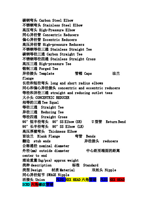
碳钢弯头 Carbon Steel Elbow不锈钢弯头 Stainless Steel Elbow高压弯头 High-Pressure Elbow同心异径管 Concentric Reducers偏心异径管 Eccentric Reducers高压异径管 High-pressure Reducers不锈钢等径三通 Stainless Straight Tee碳钢等径三通 Carbon Straight Tee不锈钢等径四通 Stainless Straight Cross高压三通 High-pressure Tee锻制三通 Forged Tee异径接头 Template 管帽 Caps 法兰flange长径和短径弯头 long and short radius elbows同心和偏心异径接头 concentric and eccentric reducers等径和异径三通 straight and reducing outlet tees大小头 CONCENTRIC REDUCER相等的三通Tee Equal等径三通Straight Tee异径三通Reducing Tee等径四通Straight Cross90°短半径弯头90°SS Elbow(SR) U型管Return Bend90°长半径弯头90°SS Elbow (LR)高压厚壁弯头Thickness Elbow盲法兰Blank Flange 弯管Bends翻边stub ends 异径接头reducers 公称通径 nominal diameter外径(mm) outside diameter 中心距至端面的距离center to end理论重量(kg/pcs) approx weight类种description 标准Standard类型Design 材质Material 双丝头 Nipple同心异径短节 SWAGE Nipple活接头 Union PLUG HEX HEAD六角管堵 PLUG HEX HEADSCRD六角螺纹管堵MPT螺纹 RC螺纹螺桩 stud SWAGE (CONC)同心异径短节单承口管箍 Half-Coupling 异径管箍Coupling, Reducing盲板 Blind Flange 带双圈的盲板spectacle blind 偏心的Ecentric 等径直通equal coupling内牙直通 female coupling外牙直通 straight tube with outside90等径弯头 90 equal elbow45等径弯头 45 equal elbow外牙弯头 male elbow内牙弯头 female elbow 等径三通 equal tee异径三通 reducing tee内牙三通female tee外牙三通 male tee 管帽cap拆除:dismantle 结头(管线的):tie-in插盲板:slip spade 盲板:blank接头:fitting 加热器:heater金属缠绕垫片(带外环):SW with outside ring 热轧on site: 管汇manifold3. 对焊管座weldolet 对焊支管台nipolet--短管支管台welding plate flange焊接板式法兰..threaded (THD) 螺纹的.sockolet 承插焊支管台...thredolet 螺纹支管台.3. 短节、双丝头 nipple... nipple 螺纹接头短节SWAGE nipple... 活接头 Union4. 螺纹接套;喷嘴nipper 钳子;拔钉钳...nipple 螺纹接套;喷嘴...noiseabatement measure 减低噪音措施• 1. 弯头支管台elbolet|弯头支管台...elbolet|弯头支管台...elbow|弯头2. 螺纹支管台;弯头管座elastometric lining橡胶内衬...elbolet螺纹支管台;弯头管座3. 斜接支管台Sockolet弯头支管台...elbolet斜接支管台trolet镶入式支管嘴Seamless---无缝的equal-----相等的,同样的Reducers----异径的,不同的blind flange--法兰堵板/盲板法兰盲法兰法兰-FLANGEblind--法兰盖,盲目的HEX==hexagon(六角形;六边形)Head--上端;前端头PLUG—管赌NIPOLET—短管斜支管台支管台NIPPLE—螺纹短节PLUG—丝堵SCD NPT--是符合NPT标准的螺纹C.STL A105 TO AP SPEC 4WPI-MWCF01 分开解释如下C.STL A105 材料标准TO AP SPEC 4WPI-MCCN01 应该符合AP(air product)规范4WPI-MCCN01BLE/PSE 大头破口,小头平面SWAGE, CON, BLE/PSE-----异径管短节同心大头破口,小头平面“o-let”=管支台螺纹支管台 threadolet 焊接支管台 weldolet 承插支管台 sockolet弯头支管台 elbolet 斜支管台latrolet 镶入式支管嘴sweeplet 短管支管台npoletPL 平端点,外丝管座承插焊(SWF)BV 斜端点对焊FL 法兰连接法兰连接在AutoCAD Plant 3D 中管道与管道元件连接形式有很多方式,详细介绍如下:端码说明链接示例(匹配)PL 平端点,外丝管座承插焊(SWF)BV 斜端点对焊THDM 外螺纹螺纹连接(THDF)THRD丝扣(THREADED) THDF 内螺纹螺纹连接(THDM)SW 内丝承插焊承插焊FL 法兰连接法兰连接WF 平头平头法兰链接(FL)LAP 搭接环搭接(PL)GRV 凹槽连接凹槽连接(PL)SO 松套平焊(PL)PPL 塑料平面熔焊PSW 内丝塑料管座胶接(PPL)LFL 直法兰LLP 直搭接LUG 接线片法兰连接(FL)BELL 钟形接头钟形接头和承插焊(SPIG)SPIG 承插焊钟形接头和承插焊(BELL)TAP 旋塞旋塞(PL)异径双承口管箍—reducing couplingCoupling, RED—异径双承口管箍FPT(缩写)=Female Pipe Thread=内螺纹管接头lateral tee--斜三通;斜侧三通FORGED--锻造inside THR-Ends—底端内侧螺纹LO TEMP=low temperature 低温。
锻制管件

产品名称 零件名称
锻制管件 1
检查员
毛坯种类 序 号 十 十一 十二 工 序 锯 检 车
A335P91
设备型号 GD4280
8744
切深 mm
数 转速 n/min
量 进给量 操作者 mm/n
30
0.3
十三 深孔 按架口及找正带找正卡紧 1.镗内孔尺寸符图 十四 车 上可调中心支撑,按内孔找正卡紧 1.车外圆尺寸符图 按(锻件产品标识和可追溯性的管理规定) 打标识 交检
18
0.5
15
0.8
编制:
审核:
批准:
Q/HY-R-JS-022 工艺编号 图 号
机 加 工 工 艺 过 程 卡
HY-QZ-001 锻件
工序内容及要求 划全线检查毛坯尺寸及余量 工件端面对主轴,按线找正卡紧 1.铣两端面见平即可 2.镗内孔做可调中心支撑的支撑面,见圆 即可,深度50mm 毛坯材质 2014年9月18日 NO.1/2 零件重量(kg) 刀具 量具 工时 h
产品名称 零件名称
锻制管件 1
检查员
毛坯种类 序 号 一 二 工 序 划 镗
A335P91
设备型号 划线平台 AF160 200盘刀 镗刀
8744
切深 mm
数 转速 n/min
量 进给量 操作者 mm/n
4 6
100 80
0.5 0.3
三
车
上可调中心支撑,按内孔找正,夹紧 1.车外圆70%见圆即可,表面Ra3.2
C61160
车刀 10 15 0.8
四 五 六
探 车
超声波探伤,合格后转入下序 在适当位置车架口及找正带 C61160 C91200 镗头 C61160 车刀 10 15 0.8 15 18 0.5 车刀 2 30 0.3
常用钢制管件(弯头、三通、异径管、管帽)理论重量体积表

常用管件产品重量/体积表使用说明1本表的管件重量依据ASME B16.9/ASME B16.11等相关规范使用的外径和壁厚进行计算,计算中适当考虑了工艺选料和制造情况对产品重量的影响(如厚度补偿);故此表所列重量为单件产品的近似净重,供参考。
表格中管表号带S的为不锈钢管件重量,其余为碳钢重量;在查阅不锈钢管件重量时应注意同一管表号的壁厚值碳钢与不锈钢可能不同。
2 90°弯头重量计算公式:W=9.685*10-6R(D2-d2)式中:W — 90°弯头重量,kg;R —弯头的曲率半径(结构尺寸),mm;D —弯头外径,mm;d —弯头内径,mm。
弯头重量公式中采用碳钢比重,即7.85kg/dm3计算。
45°、180°弯头的重量分别按90°弯头重量的1/2和2倍计算。
3钢管重量计算公式:W=0.02466T(D-T)式中:W —钢管每米长度的重量,kg/m;T —钢管壁厚,mm;D —钢管外径,mm。
钢管重量公式中采用碳钢比重,即7.85kg/dm3计算;奥氏体不锈钢管的重量为上式重量的1.015倍。
4对焊管件的重量表中列出的为常用规格的重量,对于未列入表中的同一公称通径、不同壁厚的产品重量,可用估算公式进行重量的大致估算:Q=Wt/T 式中:Q —估算的对焊管件重量,kg;W —表中同一公称通径已列出壁厚的产品重量,kg;t —估算的对焊管件的产品壁厚值,mm;T —表中同一公称通径已列出壁厚的产品壁厚值,mm。
5本表所列体积为单件产品外部轮廓体积并考虑了装箱时所占的空间,即表中所示的近似体积为单件产品所占包装物的近似体积,供参考;使用时应注意套装时体积的计算以及小件产品体积是否需要考虑等因素。
弯头理论重量表2012年09月01日更新发布:直径 壁厚(mm)mm33.544.555.566.578910111213 14 15 16 17 18 19 20 22 24 25 26 28 3018~220.06 0.07 0.07 0.09 0.10 - - - - - - - - - 说明:1、180°弯头按2倍计算,45°弯头按1/2计算;2、R=1.0DN 的弯头按2/3计算;3、表中未列出壁厚的重量,可取之相近的两个重量计算的平均值;4、90°弯头计算公式:0.0387*S(D-S)R/1000式中: S=壁厚(mm )、D=外径(mm )、R=弯曲半径(mm )25 0.10 0.11 0.12 0.14 0.15 0.16 0.17 - - - - - - - 27 0.11 0.12 0.14 0.15 0.16 0.17 0.18 - - - - - - - 32 0.13 0.15 0.16 0.18 0.20 0.21 0.23 0.24 - - - - - - 34 0.14 0.15 0.18 0.20 0.21 0.23 0.25 0.26 - - - - - - 38 0.20 0.22 0.25 0.28 0.31 0.33 0.36 0.38 0.40 - - - - - 42 0.22 0.25 0.28 0.31 0.34 0.37 0.40 0.42 0.46 - - - - - 45 0.29 0.34 0.38 0.42 0.46 0.50 0.54 0.58 0.62 0.69 - - - - 48 0.31 0.36 0.41 0.45 0.50 0.54 0.59 0.63 0.69 0.72 - - - - 51 0.33 0.39 0.44 0.49 0.53 0.58 0.63 0.67 0.72 0.80 - - - - 57 0.48 0.54 0.62 0.70 0.76 0.83 0.90 0.98 1.02 1.15 1.27 1.38 - - 60 0.50 0.58 0.66 0.73 0.81 0.88 0.95 1.02 1.09 1.22 1.35 1.47 - - 73 0.80 0.92 1.05 1.17 1.29 1.41 1.53 1.64 1.75 1.97 2.19 2.39 2.59 2.78 壁厚(mm)76 0.82 0.96 1.09 1.22 1.34 1.47 1.61 1.74 1.83 2.06 2.29 2.50 2.71 2.91 131415161718192022242526283089 1.20 1.39 1.57 1.77 1.95 2.13 2.31 2.49 2.65 3.01 3.34 3.67 3.99 4.29 - - - - - - - - - - - - - - 108 1.85 2.15 2.45 2.74 3.03 3.32 3.60 3.88 4.16 4.71 5.24 5.76 6.28 6.78 7.26 7.74 - - - - - - - - - - - - 114 1.96 2.28 2.59 2.90 3.21 3.51 3.81 4.11 4.41 4.99 5.56 6.12 6.66 7.20 7.72 8.24 - - - - - - - - - - - - 127 2.74 3.18 3.62 4.06 4.49 4.92 5.34 5.76 6.18 7.00 7.81 8.60 9.39 10.2 10.9 11.6 12.4 13.1 13.8 14.4 - - - - - - - - 133 2.87 3.33 3.80 4.25 4.71 5.16 5.61 6.05 6.49 7.36 8.34 9.05 9.87 10.7 11.5 12.1 13.0 13.8 14.5 15.2 - - - - - - - - 1403.023.514.004.494.975.645.916.386.857.778.679.5610.411.312.113.013.814.615.416.2--------159- - 5.49 6.16 6.82 7.48 8.14 8.78 9.43 10.7 12.0 13.2 14.4 15.6 16.8 18.0 19.1 20.3 21.4 22.5 23.6 24.6 26.7 - - - - - 168- - 5.81 6.52 7.22 7.92 8.61 9.30 9.99 11.3 12.7 14.0 15.3 16.6 17.9 19.1 20.3 21.6 22.7 23.9 25.1 26.2 28.5 - - - - - 219- - - - 12.6 13.9 15.1 16.3 17.5 20.0 22.3 24.7 27.0 29.3 31.6 33.9 36.1 38.3 40.5 42.7 44.9 47.0 51.2 56.3 58.3 62.1 65.9 273- - - - 19.8 21.7 23.6 25.5 27.5 31.3 35.0 38.8 42.5 46.2 49.9 53.5 56.1 60.7 64.2 67.7 71.2 74.6 81.5 88.1 91.5 94.7 101 108 325- - - - 28.3 31.1 33.9 36.6 39.4 44.9 50.3 55.7 61.1 66.4 71.7 77.0 82.2 87.4 92.6 97.7 103 108 118 128 133 138 147 157 355- - - - 36.1 39.7 43.2 46.7 50.3 57.3 64.3 71.2 78.1 84.9 91.7 98.5 105 112 119 125 132 138 151 164 170 177 189 201 377- - - - 38.4 42.2 45.9 49.7 53.4 60.9 68.3 75.7 83.1 90.4 97.6 105 112 119 126 133 140 147 161 175 182 188 202 216 406- - - - 47.3 52.0 56.7 61.3 65.9 75.2 84.3 93.5 103 112 121 130 139 148 156 165 174 182 199 217 225 233 250 266 426- - - - 49.7 54.5 59.5 64.4 69.2 78.9 88.6 98.2 108 117 127 136 146 155 164 173 183 192 210 228 237 246 263 281 457- - - - - - - - 83.6 95.4 107 119 130 142 153 165 176 187 199 210 221 232 254 276 287 298 319 340 480- - - - - - - - 87.9 100 113 125 137 149 161 173 185 197 209 221 233 244 267 290 302 313 336 358 508- - - - - - - - 103 118 132 147 161 176 190 204 218 232 246 260 274 288 315 343 356 370 396 423 529- - - - - - - - 108 123 138 153 168 183 198 213 227 242 257 271 286 300 329 357 372 386 414 441 610- - - - - - - - 150 171 192 212 233 254 275 295 316 336 357 377 397 417 458 498 517 537 576 615 630- - - - - - - - 154 176 198 220 241 262 284 305 326 348 369 390 411 432 473 514 535 555 596 637 660- - - - - - - - 175 200 225 249 274 298 323 347 371 395 419 443 467 491 538 585 609 632 679 725 711- - - - - - - - 203 232 261 289 318 346 375 403 431 459 487 515 543 571 626 681 708 735 790 844 720- - - - - - - - 206 235 264 293 322 350 380 408 437 465 493 522 550 578 634 690 717 745 800 855 762- - - - - - - - 234 267 300 333 365 398 431 463 496 528 560 592 624 656 720 783 815 846 909 971 813- - - - - - - - 266 304 341 379 416 453 491 528 565 602 638 675 712 748 821 893 929 965 1037 1108 820- - - - - - - - 269 306 344 382 420 457 495 532 570 607 644 681 718 755 828 901 938 974 1046 1118 864- - - - - - - - 301 343 386 428 470 512 554 596 638 680 722 763 805 846 928 1010 1051 1092 1173 1254 914- - - - - - - - 385 385 480 480 575 575 669 669 763 763 856 856 949 949 10421134 1226 1226 1317 1408 以上数据由武汉斯意诚贸易有限公司提供!三通理论重量表2012年09月01日更新发布:直径 壁厚(mm)mm33.544.555.566.578910111213 14 15 16 17 18 19 20 22 24 25 26 28 3018~220.06 0.07 0.07 0.09 0.10- - - - - - - - - 说明:1、表中所列重量均为等径三通重量; 1.1、二级变径均为0.94计算; 1.2、三级变径均为0.91计算; 1.3、四级变径均为0.89计算; 2、三通计算公式:0.02466*(S+1.5)(D-S-1.5)(3C-D/2)/1000式中: S=壁厚(mm )、D=外径(mm )、C=三通主管长度(mm )所有三通重量均为理论重量,仅供参考。
管件中英文对照表
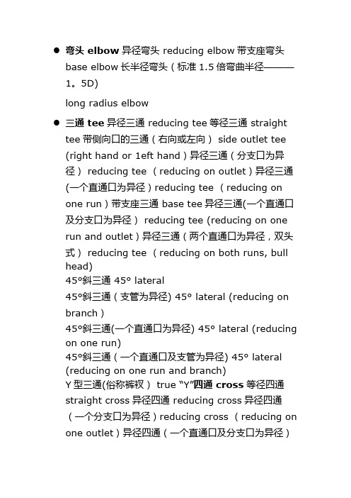
●弯头 elbow异径弯头 reducing elbow带支座弯头base elbow长半径弯头(标准1.5倍弯曲半径———1。
5D)long radius elbow●三通 tee异径三通 reducing tee等径三通 straighttee带侧向口的三通(右向或左向) side outlet tee (right hand or 1eft hand)异径三通(分支口为异径) reducing tee (reducing on outlet)异径三通(一个直通口为异径)reducing tee (reducing onone run)带支座三通 base tee异径三通(一个直通口及分支口为异径) reducing tee (reducing on one run and outlet)异径三通(两个直通口为异径,双头式) reducing tee (reducing on both runs, bull head)45°斜三通 45° lateral45°斜三通(支管为异径) 45° lateral (reducing on branch)45°斜三通(一个直通口为异径) 45° lateral (reducing on one run)45°斜三通(一个直通口及支管为异径) 45° lateral(reducing on one run and branch)Y型三通(俗称裤衩)true “Y”四通 cross等径四通straight cross异径四通 reducing cross异径四通(一个分支口为异径)reducing cross (reducing on one outlet)异径四通(一个直通口及分支口为异径)reducing cross (reducing on one run and outlet)异径四通(两个分支口为异径) reducing cross(reducing on both outlet)异径四通(一个直通口及两个分支口为异径) reducing cross (reducing on one run and both outlet)异径管 reducer同心异径管concentric reducer偏心异径管 eccentric reducer锻制异径管 reducing swage螺纹支管台threadolet 焊接支管台weldolet承插支管台sockolet弯头支管台elbolet斜接支管台latrolet镶入式支管嘴sweepolet 短管支管台nipolet支管台,插入式支管台 boss●螺纹支管台Threadolet●弯头支管台elbolet●焊接支管台weldolet;on weld●短管支管台nipolet●承插支管台sockolet●烧焊支管台weldolet●斜接支管台latrolet●承插焊支管台Sockolet●支管台,插入式支管台boss管接头 coupling, fullcoupling半管接头 half coupling异径管接头reducing coupling活接头 union内外螺纹缩接(俗称补芯) bushing管帽 cap (C)堵头 plug短节 nipple 异径短节 reducing nipple; swage nipple管道英文缩写A Anchor 固定ABS *Absolute 绝对的AISI *American Iron andSteelInstitute 美国钢铁学会ANSI *American National Standards Institute 美国国家标准学会API *American Petroleum Institute 美国石油学会APPROX *Approximate 大约,近似的ASB Asbestos 石棉ASME *American Society Of Mechanical Engineers美国机械工程师协会ASSY *Assembly 装配,组装ASTM *American Society Of Testing Material 美国材料实验协会ATM *Atmosphere 大气压AWG *American Wire Gage 美国线规AWS *American Wel**** Society 美国焊接协会AWWA *American Water WorksAssociation 美国水工协会BBB Bolted Bonnet 栓柱连接的阀盖BB By Buyer 买方供货B—B Beveled End-Beveled End 两端为坡口端BC Bolt Circle 螺栓中心圆B.C Bolted Cover(cap) 螺栓连接的阀兰盖(帽)BE Beveled End (for wel****)坡口(焊接用)B.E Bell End 承口BEP Both Ends Plain 两端平BET Both Ends Threaded 两端带螺纹BL Battery Limit 装置区边界BF Blind Flange 盲板法兰BLD Blind 盲板BLDG *Buil**** 建筑物BM Bill Of Material 材料表BOP Bottom Of Pipe 管底B-P Beveled End —Plain End 坡口端.平端BV Butterfly valve 蝶阀BWG * Birmingham Wire Gage 伯明翰线规BW Butt Weld 对焊CC Cap 管帽C—C Center to Center 中至中C—E Center to End 中至端面C—F Center to Face 中至面CH—OP Chain Operated 链条操纵的CH.PL Checkered Plate 花纹钢管C.I *Cast Iron 铸铁CL *Class 英制压力等级,等级,种类CLEAR Clearance 间隙COD Continued on Drawing 接续图COL *Column 柱,塔CONC Concentric 同心的CONN Connection 连接,接口CONT *Continue 连续CONT.V. Control Valve 控制阀CPLG Coupling 管接头,连轴节C.R. Concentric Reducer 同心异径管C.S. *Carbon Steel 碳钢C。
MSS SP-43-2008 锻制不锈钢对焊管件

MSS STANDARD PRACTICE SP-43iThis MSS Standard Practice was developed under the consensus of the MSS Technical Committee 113 and the MSS Coordinating Committee. The content of this Standard Practice is the result of the efforts of competent and concerned volunteers to provide an effective, clear, and non-exclusive specification that will benefit the industry as a whole. This MSS Standard Practice is intended as a basis for common practice by the manufacturer, the user, and the general public. The existence of an MSS Standard Practice does not in itself preclude the manufacture, sale, or use of products not conforming to the Standard Practice. Mandatory conformance is established only by reference in a code, specification, sales contract, or public law, as applicable.Unless otherwise specifically noted in this MSS SP, any standard referred to herein is identified by the date of issue that was applicable to the referenced standard(s) at the date of issue of this MSS SP. (See Annex A).This document has been substantially revised from the previous 1991 (R 2001) edition. It is suggested that if the user is interested in knowing what changes have been made, that direct page-by-page comparison should be made of this document with the previous edition .Any part of this Standard Practice may be quoted. Credit lines should read 'Extracted 432008 from MSS SP-,, with permission of the publisher, the Manufacturers Standardization Society.' Reproduction prohibited under copyright convention unless written permission is granted by the Manufacturers Standardization Society of the Valve and Fittings Industry, Inc.Originally Approved October, 1950Copyright 1982 byManufacturers Standardization Societyof theValve and Fittings Industry, Inc.Printed in U.S.A.MSS STANDARD PRACTICE SP-43FOREWORDASME B16.9 is the American Standard for steel butt-welding fittings and although not so stated, it is implied that its scope deals primarily with the schedules of wall thicknesses which are common to carbon steel and the grades of alloy steel piping that are selected for pressure and temperature considerations.The rapid expansion of the process industries in the field of chemicals, plastics, textiles, etc.,has created a demand for a class of pipe referred to as stainless piping, using this word in its generic sense.This field employs the use of the austenitic stainless steels and also nickel and its related alloys. This stainless piping is used with resistance to corrosion, elimination of product contamination, or combination of the two as the principle reason for material selection. Pressure is seldom, if ever, a critical consideration.When pressure is a consideration reference is made to ASME B16.9.Mechanical strength, resistance to vacuum, and economy, are the most usual criteria in the selection of pipe thickness in this field, and for this reason the wall thicknesses employed in the field of corrosion resistant pipe are lighter than those in common usage with carbon steel piping.In 1949 ANSI approved standard B36.19 Stainless Steel Pipe in which a schedule of wall thickness was established and designated as Schedule 10S. Numerous companies were also using a wall thickness lighter than Schedule 10S for services where contamination rather than corrosion was the prime consideration. These lighter wall thicknesses were designated Schedule 5S and the original 1950 edition of SP-43 established a series of Schedule 5S fittings. The 5S thicknesses were published in SP-43 and were developed in cooperation with representatives of the various principal chemical companiesand processing industries. In 1952 the Stainless Steel Pipe Standard B36.19 was revised to recognize the Schedule 5S wall thickness pipe as American Standard.The purpose of this Standard Practice is to provide industry with a set of dimensional standardsfor butt-welding fittings that can be used with these light wall pipes of corrosion resisting materials. The center-to-end dimensions of all fittings are identical with those in ASME B16.9 which give to industrythe advantage of uniform design room practice and a maximum utilization of existing die equipment.The only departure from this is in the lap-joint stub end where for purposes of economy the face-to-endof the product has been reduced for use with thin wall piping.The advantage of longer center-to-end dimensions of the size 3/4 elbows resulted in the changein the tables to permit a gradual changeover, providing the manufacturers ample time to deplete existing stocks, re-tool and replenish stocks.The 1991 revision of the SP was required to delete the metric equivalents.The 2001 Reaffirmation had no technical changes. There were minor editorial changes. The precedence of the longer dimensions for 3/4 elbows was made in accordance with ASME B16.9. Referenced standards were brought up to date. The title of 180 degree returns was clarified.In this 2008 edition, a minimal pressure rating is established to correspond with the ASTM CR designation.iiMSS STANDARD PRACTICE SP-43TABLE OF CONTENTSSECTION PAGE1 SCOPE (1)2 REFERENCES (1)3 PRESSURE RATINGS (1)4 SIZE (1)5 MARKING (1)6 MATERIALS (2)7 METAL THICKNESS (2)8 FITTINGS DIMENSIONS (2)9 TESTS (2)10 TOLERANCES (2)11 WELDING BEVEL (2)12 FINISH AND HEAT TREATMENT (2)TABLE1 Tolerances (3)2 Dimensions of Long Radius Elbows (4)3 Dimensions of Straight and Reducing-on-the-Outlet Tees (5)4 Dimensions of Lap-Joint Stub Ends and Caps (7)5 Dimensions of Long Radius 180 Degree Returns (8)6 Dimensions of Concentric and Eccentric Reducers (9)ANNEXA Referenced Standards and Applicable Dates (10)iiiMSS STANDARD PRACTICE SP-4311. SCOPE1.1 This Standard Practice provides dimensions, tolerances, and markings for butt-welding fittings for low pressure, corrosion resistant applications. 1.2 This Standard Practice covers only fittings made for use with Schedule 5S or 10S pipe, for all NPS sizes listed in ASME B36.19M, except that for short pattern stub ends suitable for use with Schedule 40S are also shown.2. REFERENCES2.1 Standards and specifications adopted by reference in this Standard Practice are shown in Annex A for convenience of identifying edition number, date, and source of supply.3. PRESSURE RATINGS3.1 Fittings covered by this Standard Practice are not pressure rated; however, they must be capable of withstanding 30% of the allowable pressure rating of the pipe with which they are marked. 3.2 For fittings of same pressure rating of matching pipe, refer to ASME B16.9.4. SIZE4.1 The size of the fittings in Tables 1 through 6 are identified by the corresponding nominal pipe size.5. MARKING5.1 Each fitting shall be marked to show the following:a) Manufacturer s name or trademarkb) CR followed by the material identification symbol established for the respective grade inthe appropriate ASTM or AISI specifications c) Manufacturer s heat identification number d) Schedule number or nominal wall thicknessdesignation e) Size5.2 Where the size of the fittings does not permit complete marking, Sections 5.1 a) and c) are mandatory. The other marking and identification marks may be omitted in the sequence specified in MSS SP-25.5.3 The required markings shall be made by any suitable method that is not injurious to the fitting.WROUGHT AND FABRICATED BUTT-WELDING FITTINGS FOR LOW PRESSURE, CORROSION RESISTANT APPLICATIONSMSS STANDARD PRACTICE SP-4326. MATERIALS6.1 Fittings made from AISI Types 304, 304L, 347, 316, and 316L are considered standard under this specification. Fittings made from other corrosion resistant material, including nonferrous, materials are acceptable by agreement between the purchaser and the manufacturer provided they meet the requirements of a recognized AISI or ASTM specification.7. METAL THICKNESS7.1 As these fittings are to match pipe, the dimensions of the welding ends must conform to established pipe standards as to outside diameters and tolerances. The nominal wall thickness of the fittings shall be the same as the pipe to which it is welded, except that fittings with heavier walls may be butt-welded to lighter wall pipe provided the heavier wall is tapered on the inside or outside to match the dimensions of the lighter pipe. 8. FITTINGS DIMENSIONS8.1 Inch dimensions for the fittings covered by this Standard Practice are given in Tables 1 through 6.8.2 One of the principals of this Standard Practice is the maintenance of a fixed position for welding ends with reference to center line of the fittings or the overall dimensions as the case may be. 9. TESTS9.1 Hydrostatic testing of fittings is not required in this Standard Practice; however, fittings shall be capable of withstanding a hydrostatic test pressure that is 1.5 times the pressure rating required in Section 3.1.10. TOLERANCES10.1 Table 1 lists the tolerances for the fittings covered by this Standard Practice. 11. WELDING BEVEL11.1 Fittings furnished to this Standard Practice may be finished with ends cut square for wall thickness 0.12 in. or less. For wall thicknessesin excess of 0.12 in., they shall be beveled at37 l/2plus or minus 2 l/2 withrootface(land)0.06in.plus or minus 0.03 in.MSSSTANDARD PRACTICESP-433O u t s i d e D i a m e t e r o f L a p G+ 0 - 0.03+ 0 - 0.03+ 0 - 0.03+ 0 - 0.03+ 0 - 0.06+ 0 - 0.06L a p -J o i n t S t u b E n d sF i l l e t (b )R a d i u s o f L a p A + 0 - 0.03 + 0 - 0.03 + 0 - 0.03 + 0 - 0.06 + 0 - 0.06 + 0 - 0.06 C a p sO v e r a l l L e n g t h E ± 0.12 ± 0.12 ± 0.12± 0.25 ± 0.25± 0.25A l i g n -m e n t o f E n d s U ± 0.03 ± 0.03 ± 0.03± 0.03 ± 0.06 ± 0.06 B a c k -t o - F a c e D i m e n s i o n K ± 0.25 ± 0.25 ± 0.25 ± 0.25± 0.25± 0.25 180° R e t u r n sC e n t e r -t o - C e n t e rD i m e n s i o n O ± 0.25 ± 0.25 ± 0.25 ± 0.25 ± 0.38 ± 0.38 R e d u c e r s L a p -J o i n t S t u bE n d sO v e r a l l L e n g t h F -H ± 0.06 ± 0.06 ± 0.06 ± 0.06 ± 0.09 ± 0.09 90° E l b o w s45° E l b o w sT e e sC e n t e r -t o E n dD i m e n s i o n A -B -C -M ± 0.06 ± 0.06 ± 0.06 ± 0.06 ± 0.09 ± 0.09 W a l l T h i c k -n e s s N o tl e s st h a n87½ %o fn o m i n a lt h i c k -n e s sA l l F i t t i n g s O u t s i d e (a )D i a m e t e r a t W e l d i n gE n d± 0.03± 0.03± 0.03 + 0.06 - 0.03+ 0.09 - 0.03+ 0.12 - 0.03 N o m i n a l P i p e S i z e1/2 - 1-1/22 - 3-1/245 - 810 - 1820 - 24N O T E S : D i a m e t e r a n d w a l l t h i c k n e s s e s a s s p e c i f i e d i n e i t h e r A S M E B 36.10M o r A S M E B 36.19M (a ) O u t o f r o u n d n e s s i s t h e v e c t o r s u m o f p l u s a n d m i n u s t o l e r a n c e . (b ) F i l l e t B r a d i u s i s m a x i m u m . (S e e T a b l e 4).T a b l e 1T o l e r a n c e sD i m e n s i o n s i n i n c h e sMSSSTANDARD PRACTICE SP-434TABLE 2Dimensions of Long Radius ElbowsDimensions in inchesCenter-to-EndNominal P i p e S i z eOutside Diameter At Bevel90-DegElbows A 45-DegElbows B 1/2 0.84 1.50 0.62 3/4 1.05 1.50 0.75 1 1.32 1.50 0.88 1-1/4 1.66 1.88 1.00 1-1/2 1.90 2.25 1.122 2.38 3.00 1.38 2-1/2 2.88 3.75 1.753 3.50 4.50 2.00 3-1/2 4.00 5.25 2.254 4.50 6.00 2.505 5.56 7.50 3.12 6 6.62 9.00 3.75 8 8.62 12.00 5.00 10 10.75 15.00 6.25 12 12.75 18.00 7.5014 14.00 21.00 8.75 16 16.00 24.00 10.00 18 18.00 27.00 11.25 20 20.00 30.00 12.50 22 22.00 33.00 13.50 24 24.0036.0015.00MSSSTANDARD PRACTICE SP-435TABLE 3Dimensions of Straight and Reducing-on-the-Outlet TeesDimensions in inchesNominal Outside Diameter at Bevel Center-to-End Nominal Pipe SizeRunOutletRun COutlet M1/2 Straight 0.84 0.84 1.00 1.00 3/4 Straight 1.05 1.05 1.12 1.12 3/4 x 3/4 x 1/21.050.841.121.121 Straight 1.32 1.32 1.50 1.50 1 x 1 x 3/4 1.32 1.05 1.50 1.50 1 x 1 x 1/21.320.841.501.501-1/4 Straight 1.66 1.66 1.88 1.88 1-1/4 x 1-1/4 x 1 1.66 1.32 1.88 1.88 1-1/4 x 1-1/4 x 3/4 1.66 1.05 1.88 1.88 1-1/4 x 1-1/4 x 1/21.660.841.881.881-1/2 Straight1.90 1.902.25 2.25 1-1/2 x 1-1/2 x 1-1/4 1.90 1.66 2.25 2.25 1-1/2 x 1-1/2 x 1 1.90 1.32 2.25 2.25 1-1/2 x 1-1/2 x 3/41.901.052.252.252 Straight 2.38 2.38 2.50 2.50 2 x 2 x 1-1/2 2.38 1.90 2.50 2.38 2 x 2 x 1-1/4 2.38 1.66 2.50 2.25 2 x 2 x 1 2.38 1.32 2.50 2.00 2 x 2 x 3/42.381.052.501.752-1/2 Straight 2.88 2.88 3.00 3.00 2-1/2 x 2-1/2 x 2 2.88 2.38 3.00 2.75 2-1/2 x 2-1/2 x 1-1/2 2.88 1.90 3.00 2.62 2-1/2 x 2-1/2 x 1-1/4 2.88 1.66 3.00 2.50 2-1/2 x 2-1/2 x 12.881.323.002.253 Straight 3.50 3.50 3.38 3.38 3 x 3 x 2-1/2 3.50 2.88 3.38 3.25 3 x 3 x 2 3.50 2.38 3.38 3.00 3 x 3 x 1-1/23.501.903.382.883-1/2 Straight 4.00 4.00 3.75 3.75 3-1/2 x 3-1/2 x 3 4.00 3.50 3.75 3.62 3-1/2 x 3-1/2 x 2-1/2 4.00 2.88 3.75 3.50 3-1/2 x 3-1/2 x 2 4.00 2.38 3.75 3.25 3-1/2 x 3-1/2 x 1-1/24.001.903.753.124 Straight 4.50 4.50 4.12 4.12 4 x 4 x 3-1/2 4.50 4.00 4.12 4.00 4 x 4 x 3 4.50 3.50 4.12 3.88 4 x 4 x 2-1/2 4.50 2.88 4.12 3.75 4 x 4 x 2 4.50 2.38 4.12 3.50 4 x 4 x 1-1/24.501.904.123.385 Straight 5.56 5.56 4.88 4.88 5 x 5 x 4 5.56 4.50 4.88 4.62 5 x 5 x 3-1/2 5.56 4.00 4.88 4.50 5 x 5 x 3 5.56 3.50 4.88 4.38 5 x 5 x 2-1/2 5.56 2.88 4.88 4.25 5 x 5 x 25.562.384.884.12MSS STANDARD PRACTICE SP-436TABLE 3Dimensions of Straight and Reducing-on-the-Outlet Tees(Continued)Dimensions in inchesNominal Outside Diameter at Bevel Center-to-End Run Outlet Nominal Pipe Size Run Outlet C M 6 Straight 6.62 6.62 5.62 5.62 6 x 6 x 5 6.62 5.56 5.62 5.38 6 x 6 x 4 6.62 4.50 5.62 5.12 6 x 6 x 3-1/2 6.62 4.00 5.62 5.00 6 x 6 x 3 6.62 3.50 5.62 4.88 6 x 6 x 2-1/26.622.885.624.758 Straight 8.62 8.62 7.00 7.00 8 x 8 x 6 8.62 6.62 7.00 6.62 8 x 8 x 5 8.62 5.56 7.00 6.38 8 x 8 x 4 8.62 4.50 7.00 6.12 8 x 8 x 3-1/28.624.007.006.0010 Straight 10.75 10.75 8.50 8.50 10 x 10 x 8 10.75 8.62 8.50 8.00 10 x 10 x 6 10.75 6.62 8.50 7.62 10 x 10 x 5 10.75 5.56 8.50 7.50 10 x 10 x 410.754.508.507.2512 Straight 12.75 12.75 10.00 10.00 12 x 12 x 10 12.75 10.75 10.00 9.50 12 x 12 x 8 12.75 8.62 10.00 9.00 12 x 12 x 6 12.75 6.62 10.00 8.62 12 x 12 x 512.755.5610.008.5014 Straight 14.00 14.00 11.00 11.00 14 x 14 x 12 14.00 12.75 11.00 10.62 14 x 14 x 10 14.00 10.75 11.00 10.12 14 x 14 x 8 14.00 8.62 11.00 9.75 14 x 14 x 614.006.6211.009.3816 Straight 16.00 16.00 12.00 12.00 16 x 16 x 14 16.00 14.00 12.00 12.00 16 x 16 x 12 16.00 12.75 12.00 11.62 16 x 16 x 10 16.00 10.75 12.00 11.12 16 x 16 x 8 16.00 8.62 12.00 10.75 16 x 16 x 616.006.6212.0010.3818 Straight 18.00 18.00 13.50 13.50 18 x 18 x 16 18.00 16.00 13.50 13.00 18 x 18 x 14 18.00 14.00 13.50 13.00 18 x 18 x 12 18.00 12.75 13.50 12.62 18 x 18 x 10 18.00 10.75 13.50 12.12 18 x 18 x 818.008.6213.5011.7520 Straight 20.00 20.00 15.00 15.00 20 x 20 x 18 20.00 18.00 15.00 14.50 20 x 20 x 16 20.00 16.00 15.00 14.00 20 x 20 x 14 20.00 14.00 15.00 14.00 20 x 20 x 12 20.00 12.75 15.00 13.62 20 x 20 x 10 20.00 10.75 15.00 13.12 20 x 20 x 820.008.6215.0012.7524 Straight 24.00 24.00 17.00 17.00 24 x 24 x 20 24.00 20.00 17.00 17.00 24 x 24 x 18 24.00 18.00 17.00 16.50 24 x 24 x 16 24.00 16.00 17.00 16.00 24 x 24 x 14 24.00 14.00 17.00 16.00 24 x 24 x 12 24.00 12.75 17.00 15.62 24 x 24 x 1024.0010.7517.0015.12MSS STANDARD PRACTICE SP-437MSSSTANDARD PRACTICE SP-438TABLE 5180 Dimensions of Long Radius Degree ReturnsDimensions in inchesNominal Pipe Size Outside Diameter At Bevel Center- to-CenterO Back-to-Face K 1/2 0.84 3.00 1.88 3/4 1.05 2.25 1.69 1 1.32 3.00 2.19 1-1/4 1.66 3.75 2.75 1-1/2 1.90 4.50 3.25 2 2.38 6.00 4.19 2-1/2 2.88 7.50 5.19 3 3.50 9.00 6.25 3-1/2 4.00 10.50 7.25 4 4.50 12.00 8.25 5 5.56 15.00 10.31 6 6.62 18.00 12.31 8 8.62 24.00 16.31 10 10.75 30.00 20.38 12 12.75 36.00 24.38 14 14.00 42.00 28.00 16 16.00 48.00 32.00 18 18.00 54.00 36.00 20 20.00 60.00 40.00 24 24.0072.0048.00NOTES:(a)Alignment of ends -U -for nom pipe size 8 and smaller ± 0.03 in. and for size 10 and larger ± 0.06 in. (b)A dimension is equal to 1/2 O dimension.9MSS STANDARD PRACTICE SP-43ANNEX AReferenced Standards and Applicable DatesThis Annex is an integral part of this Standard Practice and is placed after the main text for convenience. Standard Name or DescriptionASME, ANSI/ASME, ANSI, ASME/ANSIASME B16.9 2003 Factory-Made Wrought Steel Buttwelding FittingsASME B36.10M 2004 Welded and Seamless Wrought Steel PipeASME B36.19M 2004 Stainless Steel PipeMSSSP-25-1998 Standard Marking System for Valves, Fittings, Flanges and UnionsPublications of the following organizations appear in the above list:AISI American Iron and Steel Institute1101 17th Street, N.W.Washington, D.C. 20036-4700ANSI American National Standards Institute25 West 43rd StreetNew York, NY 10036ASME ASME InternationalThree Park AvenueNew York, NY 10016-5990ASTM ASTM International100 Barr Harbor DriveWest Conshohocken, PA 19428-2959MSS Manufacturers Standardization Society of the Valve and Fittings Industry, Inc.127 Park Street, N.E.Vienna, VA 22180-460210List of MSS Standard Practices(Price List Available Upon Request)NumberSP-6-2007 Standard Finishes for Contact Faces of Pipe Flanges and Connecting-End Flanges of Valves and FittingsSP-9-2008 Spot Facing for Bronze, Iron and Steel FlangesSP-25-2008 Standard Marking System for Valves, Fittings, Flanges and UnionsSP-42-2004 Class 150 Corrosion Resistant Gate, Glove, Angle and Check Valves with Flanged and Butt Weld EndsSP-43-2008 Wrought and Fabricated Butt-Welding Fittings for Low Pressure, Corrosion Resistant ApplicationsSP-44-2006 Steel Pipeline FlangesSP-45-2003 (R 08) Bypass and Drain ConnectionsSP-51-2007 Class 150LW Corrosion Resistant Flanges and Cast Flanged FittingsSP-53-1999 (R 07) Quality Standard for Steel Castings and Forgings for Valves, Flanges and Fittings and Other Piping Components - Magnetic Particle Examination MethodSP-54-1999 (R 07) Quality Standard for Steel Castings for Valves, Flanges, and Fittings and Other Piping Components - Radiographic Examination Method SP-55-2006 Quality Standard for Steel Castings for Valves, Flanges and Fittings and Other Piping Components - Visual Method for Evaluation of Surface IrregularitiesSP-58-2002 Pipe Hangers and Supports - Materials, Design and ManufactureSP-60-2004 Connecting Flange Joint Between Tapping Sleeves and Tapping ValvesSP-61-2003 Pressure Testing of Steel ValvesSP-65-2008 High Pressure Chemical Industry Flanges and Threaded Stubs for Use with Lens GasketsSP-67-2002a Butterfly ValvesSP-68-1997 (R 04) High Pressure Butterfly Valves with Offset DesignSP-69-2003 Pipe Hangers and Supports - Selection and Application (ANSI/MSS Edition)SP-70-2006 Gray Iron Gate Valves, Flanged and Threaded EndsSP-71-2005 Gray Iron Swing Check Valves, Flanged and Threaded EndsSP-72-1999 Ball Valves with Flanged or Butt-welding Ends for General ServiceSP-75-2004 Specification for High Test Wrought Butt Welding FittingsSP-77-1995 (R 00) Guidelines for Pipe Support Contractual RelationshipsSP-78-2005a Gray Iron Plug Valves, Flanged and Threaded EndsSP-79-2004 Socket-Welding Reducer InsertsSP-80-2008 Bronze Gate, Globe, Angle and Check ValvesSP-81-2006a Stainless Steel, Bonnetless, Flanged, Knife Gate ValvesSP-83-2006 Class 3000 Steel Pipe Unions, Socket-Welding and ThreadedSP-85-2002 Gray Iron Globe & Angle Valves, Flanged and Threaded EndsSP-86-2002 Guidelines for Metric Data in Standards for Valves, Flanges, Fittings and ActuatorsSP-88-1993 (R 01) Diaphragm ValvesSP-89-2003 Pipe Hangers and Supports - Fabrication and Installation PracticesSP-90-2000 Guidelines on Terminology for Pipe Hangers and SupportsSP-91-1992 (R 96) Guidelines for Manual Operation of ValvesSP-92-1999 MSS Valve User GuideSP-93-1999 (R 04) Quality Standard for Steel Castings and Forgings for Valves, Flanges, and Fittings and Other Piping Components - Liquid Penetrant Examination MethodSP-94-1999 (R 04) Quality Std for Ferritic and Martensitic Steel Castings for Valves, Flanges, and Fittings and Other Piping Components - Ultrasonic Examination MethodSP-95-2006 Swage(d) Nipples and Bull PlugsSP-96-2001 (R 05) Guidelines on Terminology for Valves and FittingsSP-97-2006 Integrally Reinforced Forged Branch Outlet Fittings - Socket Welding, Threaded and Buttwelding EndsSP-98-2001 (R 05) Protective Coatings for the Interior of Valves, Hydrants, and FittingsSP-99-1994 (R 05) Instrument ValvesSP-100-2002 Qualification Requirements for Elastomer Diaphragms for Nuclear Service Diaphragm ValvesSP-101-1989 (R 01) Part-Turn Valve Actuator Attachment - Flange and Driving Component Dimensions and Performance CharacteristicsSP-102-1989 (R 01) Multi-Turn Valve Actuator Attachment - Flange and Driving Component Dimensions and Performance CharacteristicsSP-104-2003 Wrought Copper Solder Joint Pressure FittingsSP-105-1996 (R 05) Instrument Valves for Code ApplicationsSP-106-2003 Cast Copper Alloy Flanges and Flanged Fittings, Class 125, 150 and 300SP-108-2002 Resilient-Seated Cast-Iron Eccentric Plug ValvesSP-109-1997 (R 06) Welded Fabricated Copper Solder Joint Pressure FittingsSP-110-1996 Ball Valves Threaded, Socket-Welding, Solder Joint, Grooved and Flared EndsSP-111-2001 (R 05) Gray-Iron and Ductile-Iron Tapping SleevesSP-112-1999 (R 04) Quality Standard for Evaluation of Cast Surface Finishes -Visual and Tactile Method. This SP must be sold with a 10-surface, three Dimensional Cast Surface Comparator, which is a necessary part of the Standard. Additional Comparators may be sold separately.SP-113-2001 (R 07) Connecting Joint between Tapping Machines and Tapping ValvesSP-114-2007 Corrosion Resistant Pipe Fittings Threaded and Socket Welding, Class 150 and 1000SP-115-2006 Excess Flow Valves, 1 1/4 NPS and Smaller, for Fuel Gas ServiceSP-116-2003 Service Line Valves and Fittings for Drinking Water SystemsSP-117-2006 Bellows Seals for Globe and Gate ValvesSP-118-2007 Compact Steel Globe & Check Valves - Flanged, Flangeless, Threaded & Welding Ends (Chemical & Petroleum Refinery Service)SP-119-2003 Factory-Made Belled End Socket Welding FittingsSP-120-2006 Flexible Graphite Packing System for Rising Stem Steel Valves (Design Requirements)SP-121-2006 Qualification Testing Methods for Stem Packing for Rising Stem Steel ValvesSP-122-2005 Plastic Industrial Ball ValvesSP-123-1998 (R 06) Non-Ferrous Threaded and Solder-Joint Unions for Use with Copper Water TubeSP-124-2001 Fabricated Tapping SleevesSP-125-2000 Gray Iron and Ductile Iron In-Line, Spring-Loaded, Center-Guided Check ValvesSP-126-2007 Steel In-Line Spring-Assisted Center Guided Check ValvesSP-127-2001 Bracing for Piping Systems Seismic-Wind-Dynamic Design, Selection, ApplicationSP-128-2006 Ductile Iron Gate ValvesSP-129-2003 (R 07) Copper-Nickel Socket-Welding Fittings and UnionsSP-130-2003 Bellows Seals for Instrument ValvesSP-131-2004 Metallic Manually Operated Gas Distribution ValvesSP-132-2004 Compression Packing Systems for Instrument ValvesSP-133-2005 Excess Flow Valves for Low Pressure Fuel Gas AppliancesSP-134-2006a Valves for Cryogenic Service Including Requirements for Body/Bonnet ExtensionsSP-135-2006 High Pressure Steel Knife Gate ValvesSP-136-2007 Ductile Iron Swing Check ValvesSP-137-2007 Quality Standard for Positive Material Identification of Metal Valves, Flanges, Fittings, and Other Piping Components(R-YEAR) Indicates year standard reaffirmed without substantive changesA large number of former MSS Practices have been approved by the ANSI or ANSI Standards, published by others. In order to maintain a single sourceof authoritative information, the MSS withdraws its Standard Practices in such cases.Manufacturers Standardization Society of the Valve and Fittings Industry, Inc.127 Park Street, N.E., Vienna, VA 22180-4620 (703) 281-6613 Fax # (703) 281-6671MSS-IHS SP。
- 1、下载文档前请自行甄别文档内容的完整性,平台不提供额外的编辑、内容补充、找答案等附加服务。
- 2、"仅部分预览"的文档,不可在线预览部分如存在完整性等问题,可反馈申请退款(可完整预览的文档不适用该条件!)。
- 3、如文档侵犯您的权益,请联系客服反馈,我们会尽快为您处理(人工客服工作时间:9:00-18:30)。
锻制管件(SW单价表)16可编辑版
Caps 3000LB
附件条款:
1:对不锈钢321材料按304L价上浮10%。
2:此价为SCH80、3000LB承插、螺纹管件价,如2000LB、1500LB、SCH40螺纹件同3000LB价格一样。
(DN15以下按DN15价计算,对所有规格尺寸的管件)
3:SCH160、6000LB承插件按3000LB承插价上升一级,XXS、9000LB同样按3000LB承插价上升二级
(所有管件)。
4:SCH160、6000LB螺纹件按3000LB螺纹价上升一级,XXS、9000LB同样按3000LB螺纹价上升二级
(所有管件)。
5:渐缩管有级别相差的,如上升二级加10%,三级加20%,四级加50%。
6:管座配管为4级以上价,如小于4级每级加10%。
7:电镀锌上浮10%、热浸锌上浮15%。
8:16Mn按20#/A105的价上浮10%。
9:外丝、单丝、短管为标准长度75mm;对SCH160、6000LB和XXS、9000LB按3000LB的价分别上升一级和二级。
对长度(mm)分别为L=100;120;150;200; 按此价的压力分别上升1.3;1.6;2;2.7倍。
10:此价含税、包装、采购数量大于0.5t(含0.5t)运输费在内。
低于0.5t以下的采购数量按此价上浮10%~20%。
11:特殊材料价格面议或来料加工。
12:运输方式:物流、邮递、客车。
(客车发运需贵公司接货,接货地点双方电话联系确定。
)
有效日期:2016年01月~12月。