HC三层交换机DHC配置实例HC网络设备完整版
HCL模拟三层交换机做DHCP服务器的实验

HCL模拟三层交换机做DHCP服务器的实验HCL模拟器搭建实验拓扑图结构:如上图,三层交换机S5820V2-54QS-GE_1的端口GE1/0/1连接一台PC2,PC2属于vlan 10,让其获取到192.168.10.0/24的ip地址;端口GE1/0/2连接一台host主机,host_1主机的网卡和电脑上的虚拟网卡NIC VitualBox Host-Only Ethernet Adapter #2关联。
Host_1主机让其获取到192.168.20.0/24的ip地址。
下面说一下配置思路和过程:步骤1:三层交换机划分vlan并设置vlan的管理地址,作为主机的网关:[H3C]vlan 10[H3C-vlan10]vlan 20[H3C-vlan20]quit[H3C]int vlan 10[H3C-Vlan-interface10]ip address 192.168.10.254 24[H3C-Vlan-interface10]quit[H3C]int vlan 20[H3C-Vlan-interface20]ip address 192.168.20.254 24[H3C-Vlan-interface20]quit步骤2:把相应的端口添加到vlan:[H3C]int g1/0/1[H3C-GigabitEthernet1/0/1]port link-type access[H3C-GigabitEthernet1/0/1]port access vlan 10[H3C-GigabitEthernet1/0/1]quit[H3C]int g1/0/2[H3C-GigabitEthernet1/0/2]port link-type access[H3C-GigabitEthernet1/0/2]port access vlan 20步骤3:设置DHCP地址池:我们可以查看下和dhcp相关的命令:[H3C]dhcp ?class Create a DHCP classclient Configure a DHCP clientdscp Set the Differentiated Services Codepoint (DSCP) value enable Enable DHCPlog Specify DHCP log configurationoption-group Create a DHCP option grouppolicy Configure a DHCP policyrelay Configure a DHCP relay agentserver Configure a DHCP serversmart-relay DHCP smart relaysnooping Configure DHCP snooping其中,dhcp后接server是我们要使用的命令:[H3C]dhcp server ip-pool vlan10pool 设置一个DHCP地址池名为vlan10pool [H3C-dhcp-pool-vlan10pool]network 192.168.10.0 24 设置vlan10pool分配地址段[H3C-dhcp-pool-vlan10pool]gate 按下tab键,自动补全命令[H3C-dhcp-pool-vlan10pool]gateway-list 192.168.10.254 设置地址池网关地址为三层交换机划分的vlan 10的管理ip[H3C-dhcp-pool-vlan10pool]dns[H3C-dhcp-pool-vlan10pool]dns-list 114.114.114.114 设置dns参数[H3C-dhcp-pool-vlan10pool]quit步骤4:设置vlan的DHCP工作模式首先进入到vlan 10,然后设置dhcp工作模式[H3C-Vlan-interface10]dhcp select server[H3C-Vlan-interface10]dhcp server ?apply Apply a DHCP poolcheck Check DHCP packetspolicy-first Policy-first address pool selection[H3C-Vlan-interface10]dhcp server apply ?ip-pool Specify a DHCP pool[H3C-Vlan-interface10]dhcp server apply ip-pool vlan10pool 在这里设置的为vlan10指定的地址池名(ip-pool)不能写错。
H3C三层交换机DHCP服务器配置实例
H3C三层交换机DHCP服务器配置实例H3C三层交换机DHCP服务器配置实例H3C三层交换机作为DHCP服务器,那么其中DHCP服务器要怎么配置呢?下面yjbys店铺为大家分享最新交换机作为DHCP服务器的配置实例,希望对同学们学习DHCP服务器配置有所帮助!DHCP采样UDP链接方式,服务器端口为67,客户机端口为68.实验环境(H3C ENSP)一、配置要点a:在路由器上配置DHCPserver第一步:(系统视图)开启DHCP :DHCP enable第二步:(进入接口视图)为与客户端相连的`端口配置ip地址第三步:(系统视图)建立DHCP地址池 :ip pool aaa第四步:(pool模式下)配置network网段、Gateway-list网关、dns-list DNS服务器地址、excluded-ip-address需要排除的ip 地址第五步:进入接口模式,在接口中启动DHCP动态分配:dhcp select globle第六步:将客户端的dhcp启动即可实例:路由器配置:#sysname Huawei#dhcp enable#ip pool aaagateway-list 192.168.1.1network 192.168.1.0 mask 255.255.255.0excluded-ip-address 192.168.1.10dns-list 192.168.1.10 192.168.10.10#aaaauthentication-scheme defaultauthorization-scheme defaultaccounting-scheme defaultdomain defaultdomain default_adminlocal-user admin password cipher OOCM4m($F4ajUn1vMEIBNUw#local-user admin service-type http#firewall zone Localpriority 16#interface Ethernet0/0/0ip address 192.168.1.1 255.255.255.0dhcp select global#interface Ethernet0/0/1#interface Serial0/0/0link-protocol ppp#interface Serial0/0/1link-protocol ppp#interface Serial0/0/2link-protocol ppp#interface Serial0/0/3link-protocol ppp#interface GigabitEthernet0/0/0#interface GigabitEthernet0/0/1#interface GigabitEthernet0/0/2#interface GigabitEthernet0/0/3#wlan#interface NULL0#user-interface con 0user-interface vty 0 4user-interface vty 16 20#returnb:在三层交换机中为不同vlan配置不同DHCPserver第一步:在三层交换机上建好vlan并分配好端口第二步:(系统视图)开启DHCP :DHCP enable第三步:为每一个vlan都建立一个相应的DHCP地址池(命名可以随意)第四步:为每一个地址池配置好自己相应vlan的network网段、Gateway-list网关、dns-list DNS服务器地址、excluded-ip-address需要排除的ip 地址第五步:进入每一个vlan接口,先配置好各自的ip地址,然后在启动DHCP动态分配:dhcp select globle 第六步:将客户端的dhcp启动即可实例:三层交换机配置:[Huawei]display current-configuration#sysname Huawei#vlan batch 2 to 3#cluster enablentdp enablendp enable#drop illegal-mac alarm#dhcp enable#diffserv domain default#drop-profile default#ip pool aaanetwork 192.168.1.0 mask 255.255.255.0 excluded-ip-address 192.168.1.1dns-list 192.168.10.10#ip pool bbbnetwork 192.168.2.0 mask 255.255.255.0 excluded-ip-address 192.168.2.1dns-list 192.168.10.10#aaaauthentication-scheme default authorization-scheme default accounting-scheme defaultdomain defaultdomain default_adminlocal-user admin password simple admin local-user admin service-type http#interface Vlanif1#interface Vlanif2ip address 192.168.1.1 255.255.255.0 dhcp select global#interface Vlanif3ip address 192.168.2.1 255.255.255.0 dhcp select global#interface MEth0/0/1#interface Ethernet0/0/1port link-type accessport default vlan 2#interface Ethernet0/0/2#interface Ethernet0/0/3interface Ethernet0/0/4 port link-type access port default vlan 3#interface Ethernet0/0/5 #interface Ethernet0/0/6 #interface Ethernet0/0/7 #interface Ethernet0/0/8 #interface Ethernet0/0/9 #interface Ethernet0/0/10 #interface Ethernet0/0/11 #interface Ethernet0/0/12 #interface Ethernet0/0/13 #interface Ethernet0/0/14 #interface Ethernet0/0/15 #interface Ethernet0/0/16 #interface Ethernet0/0/17interface Ethernet0/0/18#interface Ethernet0/0/19#interface Ethernet0/0/20#interface Ethernet0/0/21#interface Ethernet0/0/22#interface GigabitEthernet0/0/1 #interface GigabitEthernet0/0/2 #interface NULL0#user-interface con 0user-interface vty 0 4#return。
HCL模拟三层交换机做DHCP服务器的实验
HCL模拟三层交换机做DHCP服务器的实验HCL模拟器搭建实验拓扑图结构:如上图,三层交换机S5820V2-54QS-GE_1的端口GE1/0/1连接一台PC2,PC2属于vlan 10,让其获取到192.168.10.0/24的ip地址;端口GE1/0/2连接一台host主机,host_1主机的网卡和电脑上的虚拟网卡NIC VitualBox Host-Only Ethernet Adapter #2关联。
Host_1主机让其获取到192.168.20.0/24的ip地址。
下面说一下配置思路和过程:步骤1:三层交换机划分vlan并设置vlan的管理地址,作为主机的网关:[H3C]vlan 10[H3C-vlan10]vlan 20[H3C-vlan20]quit[H3C]int vlan 10[H3C-Vlan-interface10]ip address 192.168.10.254 24[H3C-Vlan-interface10]quit[H3C]int vlan 20[H3C-Vlan-interface20]ip address 192.168.20.254 24[H3C-Vlan-interface20]quit步骤2:把相应的端口添加到vlan:[H3C]int g1/0/1[H3C-GigabitEthernet1/0/1]port link-type access[H3C-GigabitEthernet1/0/1]port access vlan 10[H3C-GigabitEthernet1/0/1]quit[H3C]int g1/0/2[H3C-GigabitEthernet1/0/2]port link-type access[H3C-GigabitEthernet1/0/2]port access vlan 20步骤3:设置DHCP地址池:我们可以查看下和dhcp相关的命令:[H3C]dhcp ?class Create a DHCP classclient Configure a DHCP clientdscp Set the Differentiated Services Codepoint (DSCP) value enable Enable DHCPlog Specify DHCP log configurationoption-group Create a DHCP option grouppolicy Configure a DHCP policyrelay Configure a DHCP relay agentserver Configure a DHCP serversmart-relay DHCP smart relaysnooping Configure DHCP snooping其中,dhcp后接server是我们要使用的命令:[H3C]dhcp server ip-pool vlan10pool 设置一个DHCP地址池名为vlan10pool [H3C-dhcp-pool-vlan10pool]network 192.168.10.0 24 设置vlan10pool分配地址段[H3C-dhcp-pool-vlan10pool]gate 按下tab键,自动补全命令[H3C-dhcp-pool-vlan10pool]gateway-list 192.168.10.254 设置地址池网关地址为三层交换机划分的vlan 10的管理ip[H3C-dhcp-pool-vlan10pool]dns[H3C-dhcp-pool-vlan10pool]dns-list 114.114.114.114 设置dns参数[H3C-dhcp-pool-vlan10pool]quit步骤4:设置vlan的DHCP工作模式首先进入到vlan 10,然后设置dhcp工作模式[H3C-Vlan-interface10]dhcp select server[H3C-Vlan-interface10]dhcp server ?apply Apply a DHCP poolcheck Check DHCP packetspolicy-first Policy-first address pool selection[H3C-Vlan-interface10]dhcp server apply ?ip-pool Specify a DHCP pool[H3C-Vlan-interface10]dhcp server apply ip-pool vlan10pool 在这里设置的为vlan10指定的地址池名(ip-pool)不能写错。
HC三层交换机DHCP配置实例HC网络设备精编版

H C三层交换机D H C P 配置实例H C网络设备集团企业公司编码:(LL3698-KKI1269-TM2483-LUI12689-ITT289-D H C P典型配置【需求】DHCP的主要用途是:通过DHCP服务器的协助来控管各个客户机(执行中的用户端)上不可缺少的网络配置参数,包括DNS(DomainNameService?域名服务),WINS(WindowsInternetNameService?Windows互联网名字服务)等。
【组网图】在PC上执行“ipconfig”,该PC已经通过DHCP自动获取IP地址、网关、域名信息。
C:\>ipconfigWindowsIPConfigurationEthernetadapter本地连接:Connection-specificDNSSuffix.: IPAddress............:SubnetMask...........:DefaultGateway.........:【提示】1、只给出DHCPserver上最基本的配置,其它可选配置可以查看《操作手册》5.1.2DHCPRelay典型配置【需求】路由器进行DHCPRelay,将DHCP报文进行中继。
【组网图】1、DHCPServer可以使用PCServer,也可以使用路由器充当。
2、当使用路由器作为DHCPServer的配置,和上一节的配置类似。
5.1.3DHCPClient典型配置【需求】路由器作为DHCPClient,获取接口的动态IP地址。
主要用在使用路由器的以太网接口通过LAN方式接入公网的组网。
【组网图】通过dispint可以查看接口获取的IP地址[Quidway]dispinte1/0/0Ethernet1/0/0currentstate:UP?Lineprotocolcurrentstate:UPDescription:Ethernet1/0/0InterfaceTheMaximumTransmitUnitis1500,Holdtimeris10(sec) InternetAddressisacquiredviaDHCPIPSendingFrames'FormatisPKTFMT_ETHNT_2,Hardwareaddressis00e0-fc45-2ca7Mediatypeistwistedpair,loopbacknotset,promiscuousmodenotset 100Mb/s,Full-duplex,linktypeisautonegotiationOutputflow-controlisdisabled,inputflow-controlisdisabled Outputqueue:(Urgentqueue:Size/Length/Discards)0/50/0 Outputqueue:(Protocolqueue:Size/Length/Discards)0/500/0 Outputqueue:(FIFOqueuing:Size/Length/Discards)0/75/0Last300secondsinputrate0.00bytes/sec,0.00packets/secLast300secondsoutputrate0.00bytes/sec,0.00packets/secInput:406packets,57174bytes,406buffers218broadcasts,0multicasts,0pauses0errors,0runts,0giants0crc,0alignerrors,0overruns0dribbles,0drops,0nobuffersOutput:268packets,37113bytes,269buffers86broadcasts,19multicasts,0pauses0errors,0underruns,0collisions0deferred,0lostcarriers【提示】1、为了实现上网功能必须指定默认路由器。
HC三层交换机配置实例

H3C三层交换机配置实例1 网络拓扑图 02 配置要求 03划分VLAN并描述 03.1进入系统视图 03.2 创建VLAN并描述 .................................................................. 错误!未定义书签。
4 给VLAN设置网关 (1)4.1 VLAN1的IP地址设置 (1)4.2 VLAN100的网关设置 (2)4.3 VLAN101的网关设置 (2)4.4 VLAN102的网关设置 (3)4.5 VLAN103的网关设置 (3)5 给VLAN指定端口,设置端口类型 (4)5.1 VLAN100指定端口 (4)5.2 VLAN102指定端口 (5)5.3 VLAN1/101/103指定端口 (5)6 配置路由协议 (6)6.1 默认路由 (6)6.2配置流分类 (7)6.3 定义行为 (7)6.4 应用QOS策略 (8)6.5 接口配置QOS策略 (8)1 网络拓扑图图1-1 网络拓扑图2 配置要求用户1网络:172.16.1.0/24 至出口1网络:172.16.100.0/24用户2网络:192.168.1.0/24 至出口2网络:192.168.100.0/24实现功能:用户1通过互联网出口1,用户2通过互联网出口2。
3划分VLAN并描述3.1进入系统视图<H3C>system-view //进入系统视图图3-1 系统视图3.2 创建VLAN并描述[H3C]vlan 1 //本交换机使用[H3C-vlan1]description Manager //描述为“Manager”[H3C-vlan1]quit[H3C]vlan 100 //划分vlan100[H3C-vlan100]description VLAN 100 //描述为“VLAN 100”[H3C-vlan100]quit[H3C]vlan 101 //划分vlan101[H3C-vlan101]description VLAN 101 //描述为“VLAN 101”[H3C-vlan101]quit[H3C]vlan 102 //划分vlan102[H3C-vlan102]description VLAN 102 //描述为“VLAN 102”[H3C-vlan102]quit[H3C]vlan 103 //划分vlan103[H3C-vlan103]description VLAN 103 //描述为“VLAN 103”[H3C-vlan103]quit[H3C]图3-2 划分VLAN及描述4 给VLAN设置网关4.1 VLAN1的IP地址设置把VLAN1的IP地址设置为192.168.0.254,子网掩码为255.255.255.0,用于本地使用。
三层交换机详细配置实例(图)
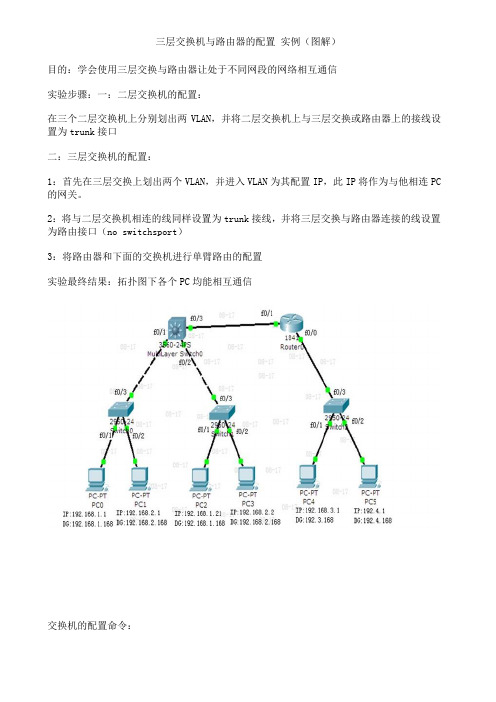
三层交换机与路由器的配置实例(图解)目的:学会使用三层交换与路由器让处于不同网段的网络相互通信实验步骤:一:二层交换机的配置:在三个二层交换机上分别划出两VLAN,并将二层交换机上与三层交换或路由器上的接线设置为trunk接口二:三层交换机的配置:1:首先在三层交换上划出两个VLAN,并进入VLAN为其配置IP,此IP将作为与他相连PC 的网关。
2:将与二层交换机相连的线同样设置为trunk接线,并将三层交换与路由器连接的线设置为路由接口(no switchsport)3:将路由器和下面的交换机进行单臂路由的配置实验最终结果:拓扑图下各个PC均能相互通信交换机的配置命令:SW 0:Switch>Switch>enSwitch#confConfiguring from terminal, memory, or network [terminal]?Enter configuration commands, one per line. End with CNTL/Z.Switch(config)#vlan 2Switch(config-vlan)#exitSwitch(config)#int f0/2Switch(config-if)#switchport access vlan 2Switch(config-if)#no shutSwitch(config-if)#int f0/3Switch(config-if)#switchport mode trunk%LINEPROTO-5-UPDOWN: Line protocol on Interface FastEthernet0/3, changed state to down%LINEPROTO-5-UPDOWN: Line protocol on Interface FastEthernet0/3, changed state to upSwitch(config-if)#exitSwitch(config)#SW 1:Switch>enSwitch#confConfiguring from terminal, memory, or network [terminal]?Enter configuration commands, one per line. End with CNTL/Z.Switch(config)#int f0/2Switch(config-if)#switchport access vlan 2% Access VLAN does not exist. Creating vlan 2Switch(config-if)#no shutSwitch(config-if)#exitSwitch(config)#int f0/3Switch(config-if)#switchport mode trunk%LINEPROTO-5-UPDOWN: Line protocol on Interface FastEthernet0/3, changed state to down%LINEPROTO-5-UPDOWN: Line protocol on Interface FastEthernet0/3, changed state to upSwitch(config-if)#SW 2:Switch>enSwitch#confConfiguring from terminal, memory, or network [terminal]?Enter configuration commands, one per line. End with CNTL/Z.Switch(config)#int f0/2Switch(config-if)#switchport access vlan 2% Access VLAN does not exist. Creating vlan 2Switch(config-if)#exitSwitch(config)#int f0/3Switch(config-if)#switchport mode trunkSwitch(config-if)#三层交换的配置命令:Switch>enSwitch#confConfiguring from terminal, memory, or network [terminal]?Enter configuration commands, one per line. End with CNTL/Z.Switch(config)#int f0/1Switch(config-if)#switchport mode trunk%LINEPROTO-5-UPDOWN: Line protocol on Interface FastEthernet0/2, changed state to downSwitch(config-if)#exitSwitch(config)#int f0/2Switch(config-if)#switchport mode trunkSwitch(config-if)#exitSwitch(config)#vlan 2Switch(config-vlan)#exitSwitch(config)#int vlan 1Switch(config-if)#no shut%LINK-5-CHANGED: Interface Vlan1, changed state to up%LINEPROTO-5-UPDOWN: Line protocol on Interface Vlan1, changed state to up Switch(config-if)#ip address 192.168.1.168 255.255.255.0Switch(config-if)#exitSwitch(config)#int vlan 2%LINK-5-CHANGED: Interface Vlan2, changed state to up%LINEPROTO-5-UPDOWN: Line protocol on Interface Vlan2, changed state to upSwitch(config-if)#ip addSwitch(config-if)#ip address 192.168.2.168 255.255.255.0Switch(config-if)#%LINK-5-CHANGED: Interface FastEthernet0/3, changed state to up%LINEPROTO-5-UPDOWN: Line protocol on Interface FastEthernet0/3, changed state to upSwitch(config-if)#exitSwitch(config)#int f0/3Switch(config-if)#no switchport%LINEPROTO-5-UPDOWN: Line protocol on Interface FastEthernet0/3, changed state to down%LINEPROTO-5-UPDOWN: Line protocol on Interface FastEthernet0/3, changed state to upSwitch(config-if)#Switch(config-if)#ip address 192.168.10.1 255.255.255.0Switch(config-if)#no shutSwitch(config-if)#exitSwitch(config)#ip routingSwitch(config-if)#exitSwitch(config)#ip route 0.0.0.0 0.0.0.0 192.168.10.2Switch(config)#路由器的配置:Router>enRouter#confConfiguring from terminal, memory, or network [terminal]?Enter configuration commands, one per line. End with CNTL/Z.Router(config)#int f0/0Router(config-if)#no shut%LINK-5-CHANGED: Interface FastEthernet0/0, changed state to upRouter(config-if)#exitRouter(config)#int f0/1Router(config-if)#no shut%LINK-5-CHANGED: Interface FastEthernet0/1, changed state to up%LINEPROTO-5-UPDOWN: Line protocol on Interface FastEthernet0/1, changed state to upRouter(config-if)#exitRouter(config)#int f0/0Router(config-if)#no shutRouter(config-if)#exitRouter(config)#int f0/0.1Router(config-subif)#encapsulation dot1Q 1Router(config-subif)#ip address 192.168.3.168 255.255.255.0Router(config-subif)#exitRouter(config)#int f0/0.2Router(config-subif)#encapsulation dot1Q 2Router(config-subif)#ip addRouter(config-subif)#ip address 192.168.4.168 255.255.255.0Router(config-subif)#exitRouter(config)#ip route 0.0.0.0 0.0.0.0 192.168.10.1Router(config)#exit%SYS-5-CONFIG_I: Configured from console by consoleRouter#confConfiguring from terminal, memory, or network [terminal]?Enter configuration commands, one per line. End with CNTL/Z.Router(config)#int f0/1Router(config-if)#ip addRouter(config-if)#ip address 192.168.10.2 255.255.255.0 Router(config-if)#。
三层交换机配置路由DHCP中继代理

三层交换机配置路由DHCP中继代理实验的目的:1.DHCP中继配置。
2.Vlan2和Vlan3的客户机能用DHCP服务器获得IP。
3.在DHCP服务器上要配置三个地址池,分别包含Vlan2和Vlan3两个网段。
4.三台机器(PC和服务器)可以用桥接的方式来连接。
实验拓扑:实验步骤1.根据拓扑图连好各设备(三层交换机采用3650,二层交换机采用2960)2.DHCP服务器建三个地址池:注意每个地址池的名称要不一样配置DHCP服务器的IP为静态:网关为:(简单就不截图,略!)3.三层交换机的配置Switch(config)#ip routing//开启三层交换机的路由功能,保证不同vlan通过三层交换机通讯Switch(config)#vlan 2 //命名VLAN2Switch(config-vlan)#vlan 3 //命名VLAN3Switch(config-vlan)#vlan 100 //命名VLAN100Switch(config-vlan)#exitSwitch(config)#int vlan 2Switch(config-if)#ip add //给VLAN2配置IPSwitch(config-if)#ip helper-address //给VLAN2配置DHCP中继Switch(config-if)#int vlan 3Switch(config-if)#ip add //给VLAN3配置IPSwitch(config-if)#ip helper-address //给VLAN3配置DHCP中继Switch(config-if)#int vlan 100Switch(config-if)#ip add //给VLAN100配置IP(VLAN100无需配置中继因为vlan100中无客户机)Switch(config-if)#int f0/1Switch (config-if)#switchport trunk encapsulation dot1q //因是三层交换机必须先配置干道(trunk)封装协议,否则配置不了接口模式Switch (config-if)#switchport mode trunk //配置接口f0/1的模式,为干道(trunk)模式4.二层交换机的配置Switch(config)#vlan 2 //命名VLAN2Switch(config-vlan)#vlan 3 //命名VLAN3Switch(config-vlan)#vlan 100 //命名VLAN100Switch(config-vlan)#exitSwitch(config)#int f0/1Switch(config-if)#switchport mode trunk //因为是二层交换机所以不需要配封装协议,2960默认为Switch(config-if)#int f0/2Switch(config-if)#switchport access vlan 2 //将接口f0/2绑定到vlan 2中Switch(config-if)#switchport mode access //将接口f0/2模式配置为access模式(此模式为直连模式,该模式一般是直接连接PC或者服务器)Switch(config-if)#int f0/3Switch(config-if)#switchport access vlan 3 //将接口f0/3绑定到vlan 3中Switch(config-if)#switchport mode access //将接口f0/3模式配置为access模式(此模式为直连模式,该模式一般是直接连接PC或者服务器)Switch(config-if)#int f0/4Switch(config-if)#switchport access vlan 100 //将接口f0/4绑定到vlan 4中Switch(config-if)#switchport mode access //将接口f0/4模式配置为access模式(此模式为直连模式,该模式一般是直接连接PC或者服务器)5.将两台PC机的IP设置为自动获得如上图,同理设置第二台PC,截图略。
华为三层交换机配置方法 命令及实例

华为三层交换机配置方法(1)(2008-07-21 11:27:34)转载分类:工作汇报标签:杂谈本文以河南平临高速所使用的华为华三通信的H3C S3600-28P-SI为例,配置前首先要确定型号后缀是SI还是EI,EI的支持所有协议,SI的不支持OSPS动态协议,因此SI配置路由时可以使用静态协议和RIP协议,具体配置如下:<H3C>system-view //进入系统视图[H3C]display current-configuration //显示当前配置//以下开始配置//第一步:划分VLAN,并描述vlan 1description local-S3600vlan 2description link-to-wenquanvlan 3description link-to-ruzhouvlan 4description link-to-xiaotunvlan 5description link-to-baofengvlan 6description link-to-pingxivlan 7description link-to-pingnanvlan 8description Uplink-to-Putianvlan 9description link-to-pingxicentre//(2)配静态路由(只用对远101 in101 in101 in101 in0.0.0cisco 35500.0.0华为三层交换机配置实例一例网络技术2008-07-25 06:08:28 阅读243 评论0 字号:大中小订阅华为三层交换机配置实例一例0.0.0华为路由器与CISCO路由器在配置上的差别"华为路由器与同档次的CISCO路由器在功能特性与配置界面上完全一致,有些方面还根据国内用户的需求作了很好的改进。
例如中英文可切换的配置与调试界面,使中文用户再也不用面对着一大堆的英文专业单词而无从下手了。
- 1、下载文档前请自行甄别文档内容的完整性,平台不提供额外的编辑、内容补充、找答案等附加服务。
- 2、"仅部分预览"的文档,不可在线预览部分如存在完整性等问题,可反馈申请退款(可完整预览的文档不适用该条件!)。
- 3、如文档侵犯您的权益,请联系客服反馈,我们会尽快为您处理(人工客服工作时间:9:00-18:30)。
H C三层交换机D H C配置实例H C网络设备
集团标准化办公室:[VV986T-J682P28-JP266L8-68PNN]
DHCP典型配置
【需求】
DHCP的主要用途是:通过DHCP服务器的协助来控管各个客户机(执行中的用户端)上不可缺少的网络配置参数,包括DNS(DomainNameService?域名服务),WINS(WindowsInternetNameService?Windows互联网名字服务)等。
【组网图】
在PC上执行“ipconfig”,该PC已经通过DHCP自动获取IP地址、网关、域名信息。
C:\>ipconfig
WindowsIPConfiguration
Ethernetadapter本地连接:
Connection-specificDNSSuffix.: IPAddress............:
SubnetMask...........:
DefaultGateway.........:
【提示】
1、只给出DHCPserver上最基本的配置,其它可选配置可以查看《操作手册》
5.1.2DHCPRelay典型配置
【需求】
路由器进行DHCPRelay,将DHCP报文进行中继。
【组网图】
1、DHCPServer可以使用PCServer,也可以使用路由器充当。
2、当使用路由器作为DHCPServer的配置,和上一节的配置类似。
5.1.3DHCPClient典型配置
【需求】
路由器作为DHCPClient,获取接口的动态IP地址。
主要用在使用路由器的以太网接口通过LAN方式接入公网的组网。
【组网图】
通过dispint可以查看接口获取的IP地址
[Quidway]dispinte1/0/0
Ethernet1/0/0currentstate:UP?
Lineprotocolcurrentstate:UP
Description:
Ethernet1/0/0Interface
TheMaximumTransmitUnitis1500,Holdtimeris10(sec) InternetAddressisacquiredviaDHCP
IPSendingFrames'FormatisPKTFMT_ETHNT_2,Hardwareaddressis00e0-fc45-
2ca7
Mediatypeistwistedpair,loopbacknotset,promiscuousmodenotset
100Mb/s,Full-duplex,linktypeisautonegotiation
Outputflow-controlisdisabled,inputflow-controlisdisabled Outputqueue:(Urgentqueue:Size/Length/Discards)
0/50/0
Outputqueue:(Protocolqueue:Size/Length/Discards)0/500/0 Outputqueue:(FIFOqueuing:Size/Length/Discards)
0/75/0
Last300secondsinputrate0.00bytes/sec,0.00packets/sec
Last300secondsoutputrate0.00bytes/sec,0.00packets/sec
Input:406packets,57174bytes,406buffers
218broadcasts,0multicasts,0pauses
0errors,0runts,0giants
0crc,0alignerrors,0overruns
0dribbles,0drops,0nobuffers
Output:268packets,37113bytes,269buffers
86broadcasts,19multicasts,0pauses
0errors,0underruns,0collisions
0deferred,0lostcarriers?
【提示】
1、为了实现上网功能必须指定默认路由器。
该网关的地址可以通过
debugdhcpclientpacket获得。
将设备的默认路由指向该网关就可以了。
该默认网关一般都是固定不变的,不会随地址的获取和释放而变化。