三层交换机详细配置实例(图)
H3C三层交换机配置实例

H3C三层交换机配置实例H3C三层交换机配置实例1 网络拓扑图 02 配置要求 03划分VLAN并描述 (1)3.1进入系统视图 (1)3.2 创建VLAN并描述 (1)4 给VLAN设置网关 (2)4.1 VLAN1的IP地址设置 (2)4.2 VLAN100的网关设置 (2)4.3 VLAN101的网关设置 (2)4.4 VLAN102的网关设置 (3)4.5 VLAN103的网关设置 (3)5 给VLAN指定端口,设置端口类型 (3)5.1 VLAN100指定端口 (3)5.2 VLAN102指定端口 (4)5.3 VLAN1/101/103指定端口 (4)6 配置路由协议 (5)6.1 默认路由 (5)6.2配置流分类 (5)6.3 定义行为 (5)6.4 应用QOS策略 (6)6.5 接口配置QOS策略 (6)1 网络拓扑图图1-1 网络拓扑图2 配置要求用户1网络:172.16.1.0/24 至出口1网络:172.16.100.0/24 用户2网络:192.168.1.0/24 至出口2网络:192.168.100.0/24实现功能:用户1通过互联网出口1,用户2通过互联网出口2。
3划分VLAN并描述3.1进入系统视图<H3C>system-view //进入系统视图图3-1 系统视图3.2 创建VLAN并描述[H3C]vlan 1 //本交换机使用[H3C-vlan1]description Manager //描述为“Manager”[H3C-vlan1]quit[H3C]vlan 100 //划分vlan100[H3C-vlan100]description VLAN 100 //描述为“VLAN 100”[H3C-vlan100]quit[H3C]vlan 101 //划分vlan101[H3C-vlan101]description VLAN 101 //描述为“VLAN 101”[H3C-vlan101]quit[H3C]vlan 102 //划分vlan102[H3C-vlan102]description VLAN 102 //描述为“VLAN 102”[H3C-vlan102]quit[H3C]vlan 103 //划分vlan103[H3C-vlan103]description VLAN 103 //描述为“VLAN 103”[H3C-vlan103]quit[H3C]图3-2 划分VLAN及描述4 给VLAN设置网关4.1 VLAN1的IP地址设置把VLAN1的IP地址设置为192.168.0.254,子网掩码为255.255.255.0,用于本地使用。
三层交换机的配置实例

三层交换机的配置实例三层交换机的配置实例1、交换机配置模版(以迈普4152E 交换机为例)hostname HEBSJZZXCG5_WN_AS02service password-encryptno service new-encryptservice login-secureenable password maipuuser admin password 0 adminip access-list standard 110 permit 10.59.16.0 0.0.0.25520 permit 10.59.18.0 0.0.0.255exitip access-list standard telnet_acl10 permit 10.59.16.0 0.0.0.25520 permit 100.255.1.0 0.0.0.25530 permit 100.255.0.0 0.0.0.255exitaaa new-modelaaa authentication login default tacacs localaaa authentication enable default tacacs enableaaa authorization exec default tacacs localaaa authorization commands 1 default tacacs local aaa authorization commands 15 default tacacs local aaa accounting exec default start-stop tacacsaaa accounting commands 1 default start-stop tacacs aaa accounting commands 15 default start-stop tacacs ip ctrl-protocol unicastip ctrl-protocol multicastip load-sharing per-destinationvlan 1exitvlan 2021description TO-HEBSJZZX3_WN_AS01 exit vlan 2051description TO-2600C-ABISexitvlan 2052description TO-2600C-OAexitvlan 2053description TO-2600C-TESTexit!slot_0_S4152E!slot 0/0port 0/0/0port-type nniport access vlan 2021exitport 0/0/1port-type nniport access vlan 2021exitport 0/0/2port-type nniport access vlan 2021exitport 0/0/3port-type nniport access vlan 2021 exitport 0/0/4port-type nniport access vlan 2021 exitport 0/0/5port-type nniexitport 0/0/6port-type nniport access vlan 2021 exit port 0/0/7port-type nniport access vlan 2021 exit port 0/0/8port-type nniport access vlan 2021 exit port 0/0/9port-type nniport access vlan 2021 exit port 0/0/10port-type nniport access vlan 2021 exit port 0/0/11port-type nniport access vlan 2021 exit port 0/0/12port-type nniport access vlan 2021 exitport-type nniport access vlan 2021 exit port 0/0/14port-type nniport access vlan 2021 exit port 0/0/15port-type nniport access vlan 2021 exit port 0/0/16port-type nniexitport 0/0/17port-type nniport access vlan 2021 exit port 0/0/18port-type nniport access vlan 2021 exit port 0/0/19port-type nniport access vlan 2021 exit port 0/0/20port-type nniport access vlan 2021 exit port 0/0/21port-type nniport access vlan 2021 exit port 0/0/22port-type nniport access vlan 2021 exitport-type nniport access vlan 2021 exit port 0/0/24port-type nniport access vlan 2021 exit port 0/0/25port-type nniport access vlan 2021 exit port 0/0/26port-type nniport access vlan 2021 exit port 0/0/27port-type nniexitport 0/0/28port-type nniport access vlan 2021 exit port 0/0/29port-type nniport access vlan 2021 exit port 0/0/30port-type nniport access vlan 2021 exit port 0/0/31port-type nniport access vlan 2021 exit port 0/0/32port-type nniport access vlan 2051 exitport-type nniport access vlan 2051 exit port 0/0/34port-type nniport access vlan 2051 exit port 0/0/35port-type nniport access vlan 2051 exit port 0/0/36port-type nniport access vlan 2051 exit port 0/0/37port-type nniport access vlan 2051 exit port 0/0/38port-type nniexitport 0/0/39port-type nniport access vlan 2051 exitport 0/0/40port-type nniport access vlan 2051 exitport 0/0/41port-type nniport access vlan 2051 exitport-type nniport access vlan 2052exitport 0/0/43port-type nniport access vlan 2052exitport 0/0/44port-type nniport access vlan 2052exitport 0/0/45port-type nniport access vlan 2052exitport 0/0/46description TO-HEBSJZZX2_WN_AS03 port-type nni port mode trunkport trunk allowed vlan allport trunk pvid vlan 1traffic-shape 10240 12288exitport 0/0/47description TO-2600Cport-type nniport mode trunkport trunk allowed vlan allport trunk pvid vlan 1!end!slot_1_SM41-4GE!slot 0/1port 0/1/0port-type nniport access vlan 2053exitport 0/1/1port-type nniport access vlan 2053exitport 0/1/2port-type nniexitport 0/1/3port-type nniexitinterface vlan 1description TO-9512E-GUANLIip address 100.255.1.131 255.255.255.0exitip route 0.0.0.0 0.0.0.0 100.255.1.254logging 10.59.18.1 0 6line vty 0 15exec-timeout 0 300login localexitsnmp-server startsnmp-server view default 1.3.6.1 includesnmp-server community public view default ro 1snmp-server host 130.25.2.103 traps community publicversion 2 snmp-server trap-source 10.6.24.222 snmp-server enable traps snmp authentication snmp-server enable traps snmp linkdownsnmp-server enable traps snmp linkup2、配置操作3、网点迈普4152E交换机配置模版enaconf tvlan 2051description ABISexitvlan 2052description OAexitvlan 2053description TESTexitvlan 2054description waiwangexitport 0/0/0-0/0/47port-type nniport 0/0/0-0/0/29port access vlan 2051exitport 0/0/30-0/0/39port access vlan 2052exitport 0/0/40-0/0/44port access vlan 2054exitport 0/0/45-0/0/47port access vlan 2053 exit exitwr。
华为三层交换机配置实例一例
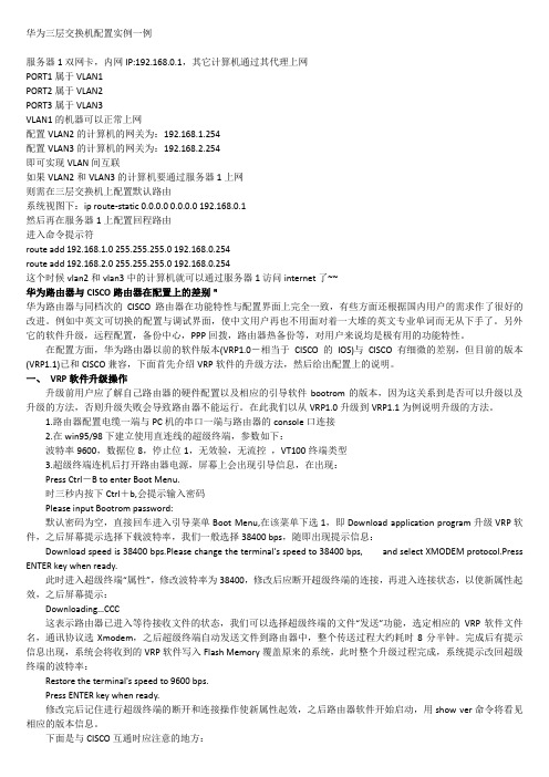
华为三层交换机配置实例一例服务器1双网卡,内网IP:192.168.0.1,其它计算机通过其代理上网PORT1属于VLAN1PORT2属于VLAN2PORT3属于VLAN3VLAN1的机器可以正常上网配置VLAN2的计算机的网关为:192.168.1.254配置VLAN3的计算机的网关为:192.168.2.254即可实现VLAN间互联如果VLAN2和VLAN3的计算机要通过服务器1上网则需在三层交换机上配置默认路由系统视图下:ip route-static 0.0.0.0 0.0.0.0 192.168.0.1然后再在服务器1上配置回程路由进入命令提示符route add 192.168.1.0 255.255.255.0 192.168.0.254route add 192.168.2.0 255.255.255.0 192.168.0.254这个时候vlan2和vlan3中的计算机就可以通过服务器1访问internet了~~华为路由器与CISCO路由器在配置上的差别"华为路由器与同档次的CISCO路由器在功能特性与配置界面上完全一致,有些方面还根据国内用户的需求作了很好的改进。
例如中英文可切换的配置与调试界面,使中文用户再也不用面对着一大堆的英文专业单词而无从下手了。
另外它的软件升级,远程配置,备份中心,PPP回拨,路由器热备份等,对用户来说均是极有用的功能特性。
在配置方面,华为路由器以前的软件版本(VRP1.0-相当于CISCO的IOS)与CISCO有细微的差别,但目前的版本(VRP1.1)已和CISCO兼容,下面首先介绍VRP软件的升级方法,然后给出配置上的说明。
一、VRP软件升级操作升级前用户应了解自己路由器的硬件配置以及相应的引导软件bootrom的版本,因为这关系到是否可以升级以及升级的方法,否则升级失败会导致路由器不能运行。
在此我们以从VRP1.0升级到VRP1.1为例说明升级的方法。
HC三层交换机配置实例

H3C三层交换机配置实例1 网络拓扑图 02 配置要求 03划分VLAN并描述 03.1进入系统视图 03.2 创建VLAN并描述 .................................................................. 错误!未定义书签。
4 给VLAN设置网关 (1)4.1 VLAN1的IP地址设置 (1)4.2 VLAN100的网关设置 (2)4.3 VLAN101的网关设置 (2)4.4 VLAN102的网关设置 (3)4.5 VLAN103的网关设置 (3)5 给VLAN指定端口,设置端口类型 (4)5.1 VLAN100指定端口 (4)5.2 VLAN102指定端口 (5)5.3 VLAN1/101/103指定端口 (5)6 配置路由协议 (6)6.1 默认路由 (6)6.2配置流分类 (7)6.3 定义行为 (7)6.4 应用QOS策略 (8)6.5 接口配置QOS策略 (8)1 网络拓扑图图1-1 网络拓扑图2 配置要求用户1网络:172.16.1.0/24 至出口1网络:172.16.100.0/24用户2网络:192.168.1.0/24 至出口2网络:192.168.100.0/24实现功能:用户1通过互联网出口1,用户2通过互联网出口2。
3划分VLAN并描述3.1进入系统视图<H3C>system-view //进入系统视图图3-1 系统视图3.2 创建VLAN并描述[H3C]vlan 1 //本交换机使用[H3C-vlan1]description Manager //描述为“Manager”[H3C-vlan1]quit[H3C]vlan 100 //划分vlan100[H3C-vlan100]description VLAN 100 //描述为“VLAN 100”[H3C-vlan100]quit[H3C]vlan 101 //划分vlan101[H3C-vlan101]description VLAN 101 //描述为“VLAN 101”[H3C-vlan101]quit[H3C]vlan 102 //划分vlan102[H3C-vlan102]description VLAN 102 //描述为“VLAN 102”[H3C-vlan102]quit[H3C]vlan 103 //划分vlan103[H3C-vlan103]description VLAN 103 //描述为“VLAN 103”[H3C-vlan103]quit[H3C]图3-2 划分VLAN及描述4 给VLAN设置网关4.1 VLAN1的IP地址设置把VLAN1的IP地址设置为192.168.0.254,子网掩码为255.255.255.0,用于本地使用。
三层交换机路由配置实例

三层交换机路由配置一、三层交换机VLAN间路由建立某公司有两个主要部门:技术部和销售部,分处于不同的办公室,为了安全和便于管理对两个部门的主机进行了VLAN划分,技术部和销售部分处于不同VLAN。
现由于业务需要销售部和技术部的主机能够相互访问,获得相应资源,两个部门的交换机通过一台三层交换机进行连接。
在交换机上建立2个Vlan:Vlan10分配给技术部及Vlan20分配给销售部。
为了实现两部门的主机能够相互访问,在三层交换机上开启路由功能,并在Vlan10中设置IP地址为192.168.10.1;在Vlan20中设置IP地址为192.168.20.1,查看三层交换机路由表,会发现在三层交换机路由表内有2条直连路由信息,实现在不同网络之间路由数据包,从而达到2个部门的主机可以相互访问,拓朴图如图所示。
第1步:开启三层交换机路由功能Switch#configure terminalSwitch(config)#hostname s3550S3550(conifg)#ip routing第2步:建立Vlan,并分配端口S3550(conifg)#vlan 10S3550(config-vlan)#name salesS3550(config-vlan)#exitS3550(conifg)#vlan 20S3550(config-vlan)#name technicalS3550(config-vlan)#exitS3550(conifg)#S3550(conifg)#interface fastethernet 0/10S3550(conifg-if)#switchport mode accessS3550(conifg-if)#switchport access vlan 10S3550(conifg-if)#exitS3550(conifg)# interface fastethernet 0/20S3550(conifg-if)#switchport mode accessS3550(conifg-if)#switchport access vlan 20S3550(config-vlan)#exitS3550(config)#第3步:配置三层交换机端口的路由功能S3550(config)#interface vlan 10S3550(conifg-if)#ip address 192.168.10.1 255.255.255.0 S3550(conifg-if)#no shutdownS3550(conifg-if)#exitS3550(config)#interface vlan 20S3550(conifg-if)#ip address 192.168.20.1 255.255.255.0S3550(conifg-if)#no shutdownS3550(conifg-if)#endS3550#第4步:查看路由表S3550#show ip route第5步:测试三层交换机Vlan间路由功能二、三层交换机与路由器间静态路由的建立某校园局域网由若干台交换机构成,现学校需要将校园网接入互联网,学校在出口使用一台路由器连接互联网。
三层交换机详细配置实例(图)
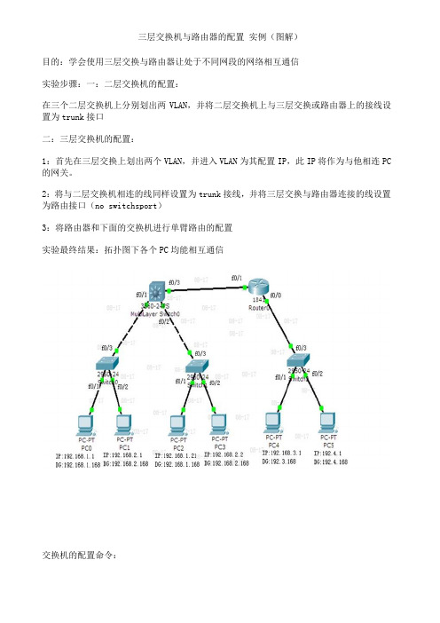
三层交换机与路由器的配置实例(图解)目的:学会使用三层交换与路由器让处于不同网段的网络相互通信实验步骤:一:二层交换机的配置:在三个二层交换机上分别划出两VLAN,并将二层交换机上与三层交换或路由器上的接线设置为trunk接口二:三层交换机的配置:1:首先在三层交换上划出两个VLAN,并进入VLAN为其配置IP,此IP将作为与他相连PC 的网关。
2:将与二层交换机相连的线同样设置为trunk接线,并将三层交换与路由器连接的线设置为路由接口(no switchsport)3:将路由器和下面的交换机进行单臂路由的配置实验最终结果:拓扑图下各个PC均能相互通信交换机的配置命令:SW 0:Switch>Switch>enSwitch#confConfiguring from terminal, memory, or network [terminal]?Enter configuration commands, one per line. End with CNTL/Z.Switch(config)#vlan 2Switch(config-vlan)#exitSwitch(config)#int f0/2Switch(config-if)#switchport access vlan 2Switch(config-if)#no shutSwitch(config-if)#int f0/3Switch(config-if)#switchport mode trunk%LINEPROTO-5-UPDOWN: Line protocol on Interface FastEthernet0/3, changed state to down%LINEPROTO-5-UPDOWN: Line protocol on Interface FastEthernet0/3, changed state to upSwitch(config-if)#exitSwitch(config)#SW 1:Switch>enSwitch#confConfiguring from terminal, memory, or network [terminal]?Enter configuration commands, one per line. End with CNTL/Z.Switch(config)#int f0/2Switch(config-if)#switchport access vlan 2% Access VLAN does not exist. Creating vlan 2Switch(config-if)#no shutSwitch(config-if)#exitSwitch(config)#int f0/3Switch(config-if)#switchport mode trunk%LINEPROTO-5-UPDOWN: Line protocol on Interface FastEthernet0/3, changed state to down%LINEPROTO-5-UPDOWN: Line protocol on Interface FastEthernet0/3, changed state to upSwitch(config-if)#SW 2:Switch>enSwitch#confConfiguring from terminal, memory, or network [terminal]?Enter configuration commands, one per line. End with CNTL/Z.Switch(config)#int f0/2Switch(config-if)#switchport access vlan 2% Access VLAN does not exist. Creating vlan 2Switch(config-if)#exitSwitch(config)#int f0/3Switch(config-if)#switchport mode trunkSwitch(config-if)#三层交换的配置命令:Switch>enSwitch#confConfiguring from terminal, memory, or network [terminal]?Enter configuration commands, one per line. End with CNTL/Z.Switch(config)#int f0/1Switch(config-if)#switchport mode trunk%LINEPROTO-5-UPDOWN: Line protocol on Interface FastEthernet0/2, changed state to downSwitch(config-if)#exitSwitch(config)#int f0/2Switch(config-if)#switchport mode trunkSwitch(config-if)#exitSwitch(config)#vlan 2Switch(config-vlan)#exitSwitch(config)#int vlan 1Switch(config-if)#no shut%LINK-5-CHANGED: Interface Vlan1, changed state to up%LINEPROTO-5-UPDOWN: Line protocol on Interface Vlan1, changed state to up Switch(config-if)#ip address 192.168.1.168 255.255.255.0Switch(config-if)#exitSwitch(config)#int vlan 2%LINK-5-CHANGED: Interface Vlan2, changed state to up%LINEPROTO-5-UPDOWN: Line protocol on Interface Vlan2, changed state to upSwitch(config-if)#ip addSwitch(config-if)#ip address 192.168.2.168 255.255.255.0Switch(config-if)#%LINK-5-CHANGED: Interface FastEthernet0/3, changed state to up%LINEPROTO-5-UPDOWN: Line protocol on Interface FastEthernet0/3, changed state to upSwitch(config-if)#exitSwitch(config)#int f0/3Switch(config-if)#no switchport%LINEPROTO-5-UPDOWN: Line protocol on Interface FastEthernet0/3, changed state to down%LINEPROTO-5-UPDOWN: Line protocol on Interface FastEthernet0/3, changed state to upSwitch(config-if)#Switch(config-if)#ip address 192.168.10.1 255.255.255.0Switch(config-if)#no shutSwitch(config-if)#exitSwitch(config)#ip routingSwitch(config-if)#exitSwitch(config)#ip route 0.0.0.0 0.0.0.0 192.168.10.2Switch(config)#路由器的配置:Router>enRouter#confConfiguring from terminal, memory, or network [terminal]?Enter configuration commands, one per line. End with CNTL/Z.Router(config)#int f0/0Router(config-if)#no shut%LINK-5-CHANGED: Interface FastEthernet0/0, changed state to upRouter(config-if)#exitRouter(config)#int f0/1Router(config-if)#no shut%LINK-5-CHANGED: Interface FastEthernet0/1, changed state to up%LINEPROTO-5-UPDOWN: Line protocol on Interface FastEthernet0/1, changed state to upRouter(config-if)#exitRouter(config)#int f0/0Router(config-if)#no shutRouter(config-if)#exitRouter(config)#int f0/0.1Router(config-subif)#encapsulation dot1Q 1Router(config-subif)#ip address 192.168.3.168 255.255.255.0Router(config-subif)#exitRouter(config)#int f0/0.2Router(config-subif)#encapsulation dot1Q 2Router(config-subif)#ip addRouter(config-subif)#ip address 192.168.4.168 255.255.255.0Router(config-subif)#exitRouter(config)#ip route 0.0.0.0 0.0.0.0 192.168.10.1Router(config)#exit%SYS-5-CONFIG_I: Configured from console by consoleRouter#confConfiguring from terminal, memory, or network [terminal]?Enter configuration commands, one per line. End with CNTL/Z.Router(config)#int f0/1Router(config-if)#ip addRouter(config-if)#ip address 192.168.10.2 255.255.255.0 Router(config-if)#。
三层交换机配置实例
三层交换机配置实例注意,为防止VTP出错,建议多保存,VTP在最后配置这个拓扑图主要实现以下功能:配置VTP域,减轻管理员工作量,配置PVST,避免环路的产生,做好DHCP 中继,使不同vlan中PC能够动态获取IP地址,设置以太网通道,增加数据流量,三层交换机配置路由功能,使不同vlan 之间的通信,大体配置和思路如下:1,IP规划:3550-1 vlan1 :192.168.1.1 255.255.255.03550-1 vlan2 :192.168.2.1 255.255.255.03550-1 vlan3 :192.168.3.1 255.255.255.03550-1 vlan4 :192.168.4.1 255.255.255.03550-2 vlan1 :192.168.1.2 255.255.255.03550-2 vlan2 :192.168.2.2 255.255.255.03550-2 vlan3 :192.168.3.2 255.255.255.03550-2 vlan4 :192.168.4.2 255.255.255.03550-2 f0/7 192.168.5.1 255.255.255.0R1 f0/1 :192.168.5.2 255.255.255.0R1 f0/2 :192.168.6.1 255.255.255.0R2 f0/1 :192.168.6.2 255.255.255.0R2 f0/2.1 :192.168.7.1 255.255.255.0R2 f0/2.2 :192.168.8.1 255.255.255.0DHCP :192.168.1.3 255.255.255.0 192.168.1.1PC1:192.168.2.3 255.255.255.0 192.168.2.1PC2:192.168.3.3 255.255.255.0 192.168.3.2PC3:192.168.4.3 255.255.255.0 192.168.4.2PC4:192.168.7.2 255.255.255.0 192.168.7.1PC5:192.168.8.2 255.255.255.0 192.168.8.12,线缆规划:SW1的f0/1端口连接3550-1 f0/1端口f0/2端口连接3550-2 f0/1端口f 0/3端口连接DHCP服务器,属于Vlan 1;SW2的f0/1端口连接3550-1 f0/2端口f0/2端口连接3550-2 f0/2端口f 0/3端口连接PC1机,属于Vlan 2;SW3的f0/1端口连接3550-1 f0/3端口f0/2端口连接3550-2 f0/3端口f 0/3端口连接PC2机,属于Vlan 3;SW4的f0/1端口连接3550-1 f0/4端口f0/2端口连接3550-2 f0/4端口f 0/3端口连接PC3机,属于Vlan 4;3550-1 f0/5 端口连接3550-2 f0/5 3550-1 f0/6 端口连接3550-2 f 0/63550-2 f0/7 端口连接R1 f0/1 R1 f0/2端口连接R2 f0/1 R2 f0/2端口连接SW5 f0/24SW5 f0/1 端口连接PC4 SW5 f0/2 端口连接PC53,VTP配置:VTP 的域名VTP 的密码配置两台3550为VTP server 模式配置其他交换机为client模式4,STP 配置:设置3550-1是Vlan1-Vlan2 的生成树根网桥设置3550-2是Vlan3-Vla n4 的生成树根网桥在接入层交换机上配置速端口和上行速链路5,三层交换机的配置:在其中一台交换机上划分Vlan; 在三层交换机上配置各个Vlan的IP地址,配置两台三层交换机之间的以太网通道(EthernetChannel)配置3550-2交换机的路由接口在三层交换机上配置RIP协议6,路由器的配置配置路由器接口的IP地址配置路由器的RIP协议在R2上配置单臂路由7,配置SW5在SW5上划分Vlan 将PC4;PC5添加进去好了,规划完了,下面我们开始命令行配置吧:3550-1的配置如下:配置交换机的三层路由功能3550-1#config terminal3550-1<config>#ip routing // 启用三层路由功能配置VTP域:3550-1>enable3550-1#config terminal3550-1<config>#vtp domain benet // 创建VTP域3550-1<config>#vtp password 123 // VTP域的密码3550-1<config>#vtp pruning // 起用VTP修剪(模拟器VTP修剪关闭,本条命令可以不做)3550-1<config>#vtp mode server // 配置交换机为vt p server模式3550-1<config>#exit // 返回下一级配置VLAN3550-1#vlan database // 进入vlan 数据库3550-1<vlan>#vlan 1 name vlan1 // 创建vlan 1 3550-1<vlan>#vlan 2 name vlan2 // 创建vlan 2 3550-1<vlan>#vlan 3 name vlan3 // 创建vlan 33550-1<vlan>#vlan 4 name vlan4 // 创建vlan 4 3550-1<vlan>#exit配置vlan IP地址:3550-1#config terminal3550-1<config>#interface vlan13550-1<config-vlan>#ip address 192.168.1.1 255.255.255.0 3550-1<config-vlan>#exit3550-1<config>#interface vlan23550-1<config-vlan>#ip address 192.168.2.1 255.255.255.0 3550-1<config-vlan>#exit3550-1<config>#interface vlan33550-1<config-vlan>#ip address 192.168.3.1 255.255.255.0 3550-1<config-vlan>#exit3550-1<config>#interface vlan43550-1<config-vlan>#ip address 192.168.4.1 255.255.255.0 3550-1<config-vlan>#exit配置RIP协议:3550-1#config terminal3550-1<config>#ip routing3550-1<config>#router rip3550-1<config-router>#network 192.168.1.03550-1<config-router>#network 192.168.2.03550-1<config-router>#network 192.168.3.03550-1<config-router>#network 192.168.4.0配置PVST:3550-1<config>#spanning-tree vlan vlan1 root primary //配置vlan1的根网桥3550-1<config>#spanning-tree vlan vlan2 root primary //配置vlan2的根网桥3550-1<config>#spanning-tree vlan vlan3 root secondary3550-1<config>#spanning-tree vlan vlan4 root secondary3550-1<config>#interface range fastEthernet 0/5 –6 //进入一定端口3550-1<config-range>#channel-group 1 mode on //配置以太网通道配置DHCP中继(模拟器可能不支持,可以不做):3550-1<config>#interface vlan vlan103550-1<config-if>#ip helper-address 192.168.1.33550-1<config>#interface vlan vlan203550-1<config-if>#ip helper-address 192.168.1.33550-2的配置如下:配置交换机的三层路由功能3550-2#config terminal3550-2<config>#ip routing配置VTP域:3550-2>enable3550-2#config terminal3550-2<config>#vtp domain benet3550-2<config>#vtp password 1233550-2<config>#vtp pruning3550-2<config>#vtp mode server3550-2<config>#exit配置vlan IP地址:3550-2#config terminal3550-2<config>#interface vlan13550-2<config-vlan>#ip address 192.168.1.2 255.255.255.0 3550-2<config-vlan>#exit3550-2<config>#interface vlan23550-2<config-vlan>#ip address 192.168.2.2 255.255.255.0 3550-2<config-vlan>#exit3550-2<config>#interface vlan33550-2<config-vlan>#ip address 192.168.3.2 255.255.255.0 3550-2<config-vlan>#exit3550-2<config>#interface vlan43550-2<config-vlan>#ip address 192.168.4.2 255.255.255.0 3550-2<config>#interface f0/73550-2<config-if>#no switchport3550-2<config-if>#ip address 192.168.5.1 255.255.255.0 3550-2<config-if>#no shotdown3550-2<config-if>#exit配置RIP协议:3550-2#config terminal3550-2<config>#router rip3550-1<config-router>#network 192.168.1.03550-1<config-router>#network 192.168.2.03550-1<config-router>#network 192.168.3.03550-1<config-router>#network 192.168.4.03550-1<config-router>#network 192.168.5.0配置PVST:3550-2<config>#spanning-tree vlan vlan3 root primary 3550-2<config>#spanning-tree vlan vlan4 root primary 3550-2<config>#spanning-tree vlan vlan1 root secondary 3550-2<config>#spanning-tree vlan vlan2 root secondary 3550-2<config>#interface range fastEthernet 0/5 –63550-2<config-if-range>#channel-group 1 mode on配置DHCP中继:3550-2<config>#interface vlan vlan33550-2<config-if>#ip helper-address 192.168.1.33550-2<config>#interface vlan vlan43550-2<config-if>#ip helper-address 192.168.1.3配置交换机:Sw1#config terminalSw1<config>#vtp domain benetSw1<config>#vtp password 123Sw1<config>#vtp mode clientSw1<config>#vtp pruningSw1<config>#interface f0/1Sw1<config-if>#switchport mode trunkSw1<config-if>#exitSw1<config>#interface f0/2Sw1<config-if>#switchport mode trunkSw1<config-if>#exitSw1<config>#interface f0/3Sw1<config-if>#switchport access vlan 1Sw1<config-if>#spanning-tree portfast //端口速链路Sw1<config-if>#exitSw1<config>#spanning-tree uplinkfast //上行速端口Sw2#config terminalSw2<config>#vtp domain benetSw2<config>#vtp password 123Sw2<config>#vtp mode clientSw1<config>#vtp pruningSw2<config>#interface f0/1Sw2<config-if>#switchport mode trunkSw2<config-if>#exitSw2<config>#interface f0/2Sw2<config-if>#switchport mode trunkSw2<config-if>#exitSw2<config>#interface f0/3Sw2<config-if>#switchport access vlan 2Sw2<config-if>#spanning-tree portfastSw2<config-if>#exitSw2<config>#spanning-tree uplinkfastSw3#config terminalSw3<config>#vtp domain benetSw3<config>#vtp password 123Sw3<config>#vtp mode clientSw1<config>#vtp pruningSw3<config>#interface f0/1Sw3<config-if>#switchport mode trunkSw3<config-if>#exitSw3<config>#interface f0/2Sw3<config-if>#switchport mode trunkSw3<config-if>#exitSw3<config>#interface f0/3Sw3<config-if>#switchport access vlan 3Sw3<config-if>#spanning-tree portfastSw3<config-if>#exitSw3<config>#spanning-tree uplinkfastSw4#config terminalSw4<config>#vtp domain benetSw4<config>#vtp password 123Sw4<config>#vtp mode clientSw1<config>#vtp pruningSw4<config>#interface f0/1Sw4<config-if>#switchport mode trunkSw4<config-if>#exitSw4<config>#interface f0/2Sw4<config-if>#switchport mode trunkSw4<config-if>#exitSw4<config>#interface f0/3Sw4<config-if>#switchport access vlan 4Sw4<config-if>#spanning-tree portfastSw4<config-if>#exitSw4<config>#spanning-tree uplinkfastSw5 >enableSw5#config terminalSw5<config>#interface f0/24Sw5<config-if>#switchport mode trunkSw5<config-if>#endSw5#vlan databaseSw5<vlan>#vlan 1 valn1Sw5<vlan>#vlan 2 valn2Sw5<vlan>#exitSw5#config terminalSw5<config>#interface f0/1Sw5<config-if>#switchport access vlan1Sw5<config>#interface f0/2Sw5<config-if>#switchport access vlan2路由器的配置:R1>enableR1#config terminalR1<config>#interface f0/1R1<config-if>#ip address 192.168.5.2 255.255.255.0 R1<config-if>#no shotdownR1<config>#interface f0/2R1<config-if>#ip address 192.168.6.1 255.255.255.0R1<config-if>#no shotdownR1<config-if>#exitR1<config>#router ripR1<config>#network 192.168.5.0R1<config>#router ripR1<config>#network 192.168.6.0R2>enableR2#config terminalR2<config>#interface f0/1R2<config-if>#ip address 192.168.6.2 255.255.255.0R1<config-if>#no shotdownR1<config-if>#exitR1<config>#interface f0/2R1<config-if>#no shotdownR1<config-if>#exitR2<config>#interface f0/2.1R2<config-subif>#ip address 192.168.7.1 255.255.255.0R2<config-subif>#encapsolution dot1 1R2<config>#interface f0/2.2R2<config-subif>#ip address 192.168.8.1 255.255.255.0R2<config-subif>#encapsolution dot1 2R2<config-if>#exitR2<config>#router ripR2<config>#network 192.168.6.0R2<config>#router ripR2<config>#network 192.168.7.0R2<config>#router ripR2<config>#network 192.168.8.0PC4: IP: 192.168.7.2 mask:255.255.255.0 default-gateway:192. 168.7.1PC5: IP: 192.168.8.2 mask:255.255.255.0 default-gateway:192. 168.8.1实验验收:在PC1/PC2/PC3/上动态获取DHCP服务器的地址资源在PC4/PC5上ping PC1/PC2/PC3/和DHCP服务器排错事使用的命令:show run //查看所有的配置show cdp entry * //查看cisco端口连接的设备show ip router //查看本地路由表show ip interface brief //查看端口的详细信息show vlan brief //查看vlan的详细信息show vtp status //查看VTP配置信息show ip cef //查看FIB表show adjacency detail //查看邻接关系表。
鸿鹄论坛_全面的三层交换机配置实例(带命令解释)
全面的三层交换机配置实例(带命令解释)三层交换机比较全面的三层交换机配置实例(带命令解释哟!)Enable //进入私有模式Configure terminal //进入全局模式service password-encryption //对密码进行加密hostname Catalyst 3550-12T1 //给三层交换机定义名称enable password 123456. //enable密码Enable secret 654321 //enable的加密密码(应该是乱码而不是654321这样)Ip subnet-zero //允许使用全0子网(默认都是打开的)Ip name-server 172.16.8.1 172.16.8.2 //三层交换机名字Catalyst 3550-12T1对应的IP地址是172.16.8.1Service dhcp //提供DHCP服务ip routing //启用三层交换机上的路由模块ExitVtp mode server //定义VTP工作模式为sever模式Vtp domain centervtp //定义VTP域的名称为centervtpVlan 2 name vlan2 //定义vlan并给vlan取名(如果不取名的话,vlan2的名字应该是vlan002)Vlan 3 name vlan3Vlan 4 name vlan4Vlan 5 name vlan5Vlan 6 name vlan6Vlan 7 name vlan7Vlan 8 name vlan8Vlan 9 name vlan9Exitinterface Port-channel 1 //进入虚拟的以太通道组1switchport trunk encapsulation dot1q //给这个接口的trunk封装为802.1Q的帧格式switchport mode trunk //定义这个接口的工作模式为trunkswitchport trunk allowed vlan all //在这个trunk上允许所有的vlan通过Interface gigabitethernet 0/1 //进入模块0上的吉比特以太口1switchport trunk encapsulation dotlq //给这个接口的trunk封装为802.1Q的帧格式switchport mode trunk //定义这个接口的工作模式为trunkswitchport trunk allowed vlan all //在这个trunk上允许所有的vlan通过channel-group 1 mode on //把这个接口放到快速以太通道组1中Interface gigabitethernet 0/2 //同上switchport trunk encapsulation dotlqswitchport mode trunkswitchport trunk allowed vlan allchannel-group 1 mode onport-channel load-balance src-dst-ip //定义快速以太通道组的负载均衡方式(依*源和目的IP 的方式)interface gigabitethernet 0/3 //进入模块0上的吉比特以太口3switchport trunk encapsulation dotlq //给trunk封装为802.1Qswitchport mode trunk //定义这个接口的工作模式为trunkswitchport trunk allowed vlan all //允许所有vlan信息通过interface gigabitethernet 0/4 //同上switchport trunk encapsulation dotlqswitchport mode trunkswitchport trunk allowed vlan allinterface gigbitethernet 0/5 //同上switchport trunk encapsulation dotlqswitchport mode trunkswitchport trunk allowed vlan allinterface gigbitethernet 0/6 //同上switchport trunk encapsulation dotlqswitchport mode trunkswitchprot trunk allowed vlan allinterface gigbitethernet 0/7 //进入模块0上的吉比特以太口7Switchport mode access //定义这个接口的工作模式为访问模式switchport access vlan 9 //定义这个接口可以访问哪个vlan(实际就是分配这个接口到vlan)no shutdownspanning-tree vlan 6-9 cost 1000 //在生成树中,vlan6-9的开销定义为10000interface range gigabitethernet 0/8 –10 //进入模块0上的吉比特以太口8,9,10 switchport mode access //定义这些接口的工作模式为访问模式switchport access vlan 8 //把这些接口都分配到vlan8中no shutdownspanning-tree portfast //在这些接口上使用portfast(使用portfast以后,在生成树的时候不参加运算,直接成为转发状态)interface gigabitethernet 0/11 //进入模块0上的吉比特以太口11switchport trunk encapsulation dotlq //给这个接口封装为802.1Qswitchport mode trunk //定义这个接口的工作模式为trunkswitchport trunk allowed vlan all //允许所有vlan信息通过interface gigabitethernet 0/12 //同上switchport trunk encapsulation dotlqswitchport mode trunkswitchport trunk allowed vlan allinterface vlan 1 //进入vlan1的逻辑接口(不是物理接口,用来给vlan做路由用)ip address 172.16.1.7 255.255.255.0 //配置IP地址和子网掩码no shutdownstandby 1 ip 172.16.1.9 //开启了冗余热备份(HSRP),冗余热备份组1,虚拟路由器的IP地址为172.16.1.9standby 1 priority 110 preempt //定义这个三层交换机在冗余热备份组1中的优先级为110,preempt是用来开启抢占模式interface vlan 2 //同上ip address 172.16.2.252 255.255.255.0no shutdownstandby 2 ip 172.16.2.254standby 2 priority 110 preemptip access-group 101 in //在入方向上使用扩展的访问控制列表101interface vlan 3 //同上ip address 172.16.3.252 255.255.255.0no shutdownstandby 3 ip 172.16.3.254standby 3 priority 110 preemptip access-group 101 ininterface vlan 4 //同上ip address 172.16.4.252 255.255.255.0no shutdownstandby 4 ip 172.16.4.254standby 4 priority 110 preemptip access-group 101 ininterface vlan 5ip address 172.16.5.252 255.255.255.0no shutdownstandby 5 ip 172.16.5.254standby 5 priority 110 preemptip access-group 101 ininterface vlan 6ip address 172.16.6.252 255.255.255.0no shutdownstandby 6 ip 172.16.6.254standby 6 priority 100 preemptinterface vlan 7ip address 172.16.7.252 255.255.255.0no shutdownstandby 7 ip 172.16.7.254standby 7 priority 100 preemptinterface vlan 8ip address 172.16.8.252 255.255.255.0no shutdownstandby 8 ip 172.16.8.254standby 8 priority 100 preemptinterface vlan 9ip address 172.16.9.252 255.255.255.0no shutdownstandby 9 ip 172.16.9.254standby 9 priority 100 preemptaccess-list 101 deny ip any 172.16.7.0 0.0.0.255 //扩展的访问控制列表101 access-list 101 permit ip any anyInterface vlan 1 //进入vlan1这个逻辑接口Ip helper-address 172.16.8.1 //可以转发广播(helper-address的作用就是把广播转化为单播,然后发向172.16.8.1)Interface vlan 2Ip helper-address 172.16.8.1Interface vlan 3ip helper-address 172.16.8.1interface vlan 4ip helper-address 172.16.8.1interface vlan 5ip helper-address 172.16.8.1interface vlan 6ip helper-address 172.16.8.1interface vlan 7ip helper-address 172.16.8.1interface vlan 9ip helper-address 172.16.8.1router rip //启用路由协议RIPversion 2 //使用的是RIPv2,如果没有这句,则是使用RIPv1network 172.16.0.0 //宣告直连的网段exitip route 0.0.0.0 0.0.0.0 172.16.9.250 //缺省路由,所有在路由表中没有办法匹配的数据包,都发向下一跳地址为172.16.9.250这个路由器line con 0line aux 0line vty 0 15 //telnet线路(路由器只有5个,是0-4)password 12345678 //login密码loginendcopy running-config startup-config 保存配置来源: 中国系统集成论坛原文链接:/thread-3598-1-8.html。
Cisco3560三层交换机VLAN的配置案例
3、网络拓扑图
4、配置三层交换机 本例以思科三层交换机为例,具体配置命令如下所示:
1)、创建5个vlan 3560(config)#vlan 10 3560(config-vlan)#vlan 20 3560(config-vlan)#vlan 30 3560(config-vlan)#vlan 40 3560(config-vlan)#vlan 50 3560(config-vlan)#exit
2、各机房IP地址分配
机房一、二: IP:192.168.7.X/24,网关:192.168.7.254 机房三、四: IP:192.168.8.X/24,网关:192.168.8.254 机房五、六: IP:192.168.10.X/24,网关:192.168.10.254 机房七: IP:192.168.11.X/24,网关:192.168.11.254 服务器: IP:192.168.12.X/24 网关:192.168.12.254
2)、将端口划分到相应的VLAN
3560(config)#int range f0/1-5 3560(config-if-range)#switchport mode access 3560(config-if-range)#switchport access vlan10 3560(config-if-range)#exit 3560(config)#int range f0/6-10 3560(config-if-range)#switchport mode access 3560(config-if-range)#switchport access vlan20 3560(config-if-range)#exit 3560(config)#int range f0/11-15 3560(config-if-range)#switchport mode access 3560(config-if-range)#switchport access vlan30 3560(config-if-range)#exit 3560(config)#int range f0/16-20
第6章 三层交换机的配置PPT课件
10
6.2 配置交换机的静态路由
二、配置方法
SwitchA
E0/1 VLAN5 192.168.0.1 255.255.255.0
E0/1 VLAN5 192.168.0.2 255.255.255.0
SwitchB
E0/3~E0/12 VLAN2 192.0.0.1
255.255.255.0
E0/13~24 VLAN3 192.0.1.1 255.255.255.0
12
6.2 配置交换机的静态路由
配置过程及配置说明 (5)在SwitchA上验证连通性。在SwitchA上除了 192.0.2.0网段不可达以外,都可以ping通。 (6)查看路由表。在SwitchA的路由表中只有交换 机直接连接网段,由于192.0.2.0网段没有和SwitchA 直接相连,所以不能被识别。 (7)为了达到互通的目的,需要在交换机上配置到 达非直连网段的静态路由。 (8)查看路由表 (9)配置静态路由后,各网段就可以全部连通。
13
6.3 配置交换机的动态路由协议
实例6.3 某单位新购置Quidway3528G三层交换机两台,按 照图6-2连接对交换机进行RIP路由协议配置,使各 网段相互可以连接通信。 一、分析问题 1.技术概述 路由信息协议RIP运行简单,适用于小型网络。默 认以30秒为周期广播路由信息,每个路由器根据收 到的路由信息来修改本身的路由表。路由器到与它 直接相连网络的跳数为0,每通过一个路由器跳数加 1。为限制收敛时间,RIP规定metric取值0~15之间 的整数,大于15的跳数被定义为无穷大,即目的网 络或主机不可达。
4
6.1 配置VLAN间的路由
二 以太网口 E0/3~E0/12
以太网口
- 1、下载文档前请自行甄别文档内容的完整性,平台不提供额外的编辑、内容补充、找答案等附加服务。
- 2、"仅部分预览"的文档,不可在线预览部分如存在完整性等问题,可反馈申请退款(可完整预览的文档不适用该条件!)。
- 3、如文档侵犯您的权益,请联系客服反馈,我们会尽快为您处理(人工客服工作时间:9:00-18:30)。
三层交换机与路由器的配置实例(图解)目的:学会使用三层交换与路由器让处于不同网段的网络相互通信实验步骤:一:二层交换机的配置:在三个二层交换机上分别划出两VLAN,并将二层交换机上与三层交换或路由器上的接线设置为trunk接口二:三层交换机的配置:1:首先在三层交换上划出两个VLAN,并进入VLAN为其配置IP,此IP将作为与他相连PC 的网关。
2:将与二层交换机相连的线同样设置为trunk接线,并将三层交换与路由器连接的线设置为路由接口(no switchsport)3:将路由器和下面的交换机进行单臂路由的配置实验最终结果:拓扑图下各个PC均能相互通信交换机的配置命令:SW 0:Switch>Switch>enSwitch#confConfiguring from terminal, memory, or network [terminal]?Enter configuration commands, one per line. End with CNTL/Z.Switch(config)#vlan 2Switch(config-vlan)#exitSwitch(config)#int f0/2Switch(config-if)#switchport access vlan 2Switch(config-if)#no shutSwitch(config-if)#int f0/3Switch(config-if)#switchport mode trunk%LINEPROTO-5-UPDOWN: Line protocol on Interface FastEthernet0/3, changed state to down%LINEPROTO-5-UPDOWN: Line protocol on Interface FastEthernet0/3, changed state to upSwitch(config-if)#exitSwitch(config)#SW 1:Switch>enSwitch#confConfiguring from terminal, memory, or network [terminal]?Enter configuration commands, one per line. End with CNTL/Z.Switch(config)#int f0/2Switch(config-if)#switchport access vlan 2% Access VLAN does not exist. Creating vlan 2Switch(config-if)#no shutSwitch(config-if)#exitSwitch(config)#int f0/3Switch(config-if)#switchport mode trunk%LINEPROTO-5-UPDOWN: Line protocol on Interface FastEthernet0/3, changed state to down%LINEPROTO-5-UPDOWN: Line protocol on Interface FastEthernet0/3, changed state to upSwitch(config-if)#SW 2:Switch>enSwitch#confConfiguring from terminal, memory, or network [terminal]?Enter configuration commands, one per line. End with CNTL/Z.Switch(config)#int f0/2Switch(config-if)#switchport access vlan 2% Access VLAN does not exist. Creating vlan 2Switch(config-if)#exitSwitch(config)#int f0/3Switch(config-if)#switchport mode trunkSwitch(config-if)#三层交换的配置命令:Switch>enSwitch#confConfiguring from terminal, memory, or network [terminal]?Enter configuration commands, one per line. End with CNTL/Z.Switch(config)#int f0/1Switch(config-if)#switchport mode trunk%LINEPROTO-5-UPDOWN: Line protocol on Interface FastEthernet0/2, changed state to downSwitch(config-if)#exitSwitch(config)#int f0/2Switch(config-if)#switchport mode trunkSwitch(config-if)#exitSwitch(config)#vlan 2Switch(config-vlan)#exitSwitch(config)#int vlan 1Switch(config-if)#no shut%LINK-5-CHANGED: Interface Vlan1, changed state to up%LINEPROTO-5-UPDOWN: Line protocol on Interface Vlan1, changed state to up Switch(config-if)#ip address 192.168.1.168 255.255.255.0Switch(config-if)#exitSwitch(config)#int vlan 2%LINK-5-CHANGED: Interface Vlan2, changed state to up%LINEPROTO-5-UPDOWN: Line protocol on Interface Vlan2, changed state to upSwitch(config-if)#ip addSwitch(config-if)#ip address 192.168.2.168 255.255.255.0Switch(config-if)#%LINK-5-CHANGED: Interface FastEthernet0/3, changed state to up%LINEPROTO-5-UPDOWN: Line protocol on Interface FastEthernet0/3, changed state to upSwitch(config-if)#exitSwitch(config)#int f0/3Switch(config-if)#no switchport%LINEPROTO-5-UPDOWN: Line protocol on Interface FastEthernet0/3, changed state to down%LINEPROTO-5-UPDOWN: Line protocol on Interface FastEthernet0/3, changed state to upSwitch(config-if)#Switch(config-if)#ip address 192.168.10.1 255.255.255.0Switch(config-if)#no shutSwitch(config-if)#exitSwitch(config)#ip routingSwitch(config-if)#exitSwitch(config)#ip route 0.0.0.0 0.0.0.0 192.168.10.2Switch(config)#路由器的配置:Router>enRouter#confConfiguring from terminal, memory, or network [terminal]?Enter configuration commands, one per line. End with CNTL/Z.Router(config)#int f0/0Router(config-if)#no shut%LINK-5-CHANGED: Interface FastEthernet0/0, changed state to upRouter(config-if)#exitRouter(config)#int f0/1Router(config-if)#no shut%LINK-5-CHANGED: Interface FastEthernet0/1, changed state to up%LINEPROTO-5-UPDOWN: Line protocol on Interface FastEthernet0/1, changed state to upRouter(config-if)#exitRouter(config)#int f0/0Router(config-if)#no shutRouter(config-if)#exitRouter(config)#int f0/0.1Router(config-subif)#encapsulation dot1Q 1Router(config-subif)#ip address 192.168.3.168 255.255.255.0Router(config-subif)#exitRouter(config)#int f0/0.2Router(config-subif)#encapsulation dot1Q 2Router(config-subif)#ip addRouter(config-subif)#ip address 192.168.4.168 255.255.255.0Router(config-subif)#exitRouter(config)#ip route 0.0.0.0 0.0.0.0 192.168.10.1Router(config)#exit%SYS-5-CONFIG_I: Configured from console by consoleRouter#confConfiguring from terminal, memory, or network [terminal]?Enter configuration commands, one per line. End with CNTL/Z.Router(config)#int f0/1Router(config-if)#ip addRouter(config-if)#ip address 192.168.10.2 255.255.255.0 Router(config-if)#。