TG-NET万兆网卡安装教程
网卡安装和配置指南说明书
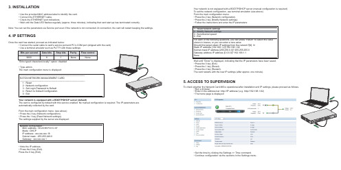
Once the card has started, proceed as indicated below: • Connect the serial cable to card’s service port and PC’s COM port (shipped with the card) • Use a terminal emulator such as PuTTY with these settings:
Bits per second Data bits Stop bits
9600
8
1
"Echo typed characters locally" option: disabled
Parity None
Flow control None
• Type admin. The main configuration menu is displayed:
3. INSTALLATION
• Use the provided MAC address label to identify the card. • Connect the ETHERNET cable. • Check the ETHERNET port indications. • Wait until the Data LED flashes regularly (approx. three minutes), indicating that card start-up has terminated correctly.
Network configuration : MAC address : 00:20:85:FD:1C:07 Mode : DHCP IP address : xxx.xxx.xxx.18 Subnet mask : 255.255.248.0 Gateway : xxx.xxx.xxx.1
JetNet 5020G 工业 16 FE 加 4 GbE SFP 以太网交换机快速安装指南 V1.
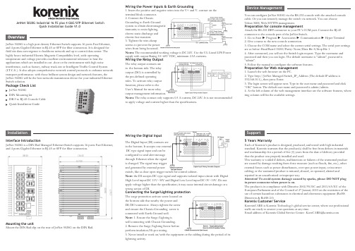
JetNet 5020G Industrial 16 FE plus 4 GbE/SFP Ethernet SwitchQuick Installation Guide V1.0JetNet 5020G is a high port density Ethernet Switch supports 16 ports Fast Ethernet, and 4 ports Gigabit Ethernet in RJ-45 or SFP for fiber connection. It is designed for field site data convergence to backbone network and up to control data center. The highly heavy industrial Electric-Magnetic Compatibility level, wide operating temperature and voltage provides excellent environmental tolerance to bear the applications which are installed in out -door or the environment with high noise interference, such as factory, railway track-site or Intelligent Traffic Control System (I.T.C.S. ). It also adopts comprehensive network control protocols to enhance network transport performance. with those brilliant system design and network features, the JetNet 5020G will be the best network transmission device for your industrial Ethernet Switch solution.Package Check ListJetNet 5020G DIN Mounting kitDB-9 to RJ-45 Console Cable Quick Installation GuideWiring the Power Inputs & Earth Grounding1. Insert the positive and negative wires into the V+ and V- contact on the terminal block connector.2. Connect the ChassisGrounding to Earth Ground system to obtain electromagnetic immunity to resist lighting, electro static discharge and electric fast transient.3. Tighten the wire-clamp screws to prevent the power wires from being loosened.Notes: The recommended working voltage is DC 24V. Use the UL Listed LPS Power supply with output Rating 10~60V VDC, minimum 2.5A currents.Wiring the Relay OutputThe relay output contacts are in the bottom side. The relay output (DO) is controlled by the pre-defined operating rules. To activate relay output function, please refer to the User’s Manual for more relay output management information.Notes: The relay contact only supports 0.5 A current, DC 24V. It is not recommended to apply voltage and current higher than the specifications.Wiring the Digital InputThe Digital Input (DI) contacts are in the bottom. It accepts one external DC type signal input and can be configured to send alert message through Ethernet when the signal is changed. The signal may trigger and generated by external powerswitch, like as door open trigger switch for control cabinet.Note: the DI accepts DC type signal and supports isolated input circuit with Digital High Level input DC 11V~30V and Digital Low Level input DC 0V~10V. Do not apply voltage higher than the specification; it may cause internal circuit damage or a wrong action of DI.Connecting the Surge/Lighting protectionThe surge protection activate screw located on the bottom side that nearby the power and DI/DO connector. Always tighten the screw and ensure the Chassis-Grounding screw is connected with Earth-Ground well.Note: 1. Ensure the Surge/Lighting is well connecting with Chassis Grounding. 2. Remove the Surge/Lighting Screw before perform insulation/Hi-pot testing.3. Never install or work on/with the equipment or the cabling during the period of its lightning activity.You can configure JetNet 5020G via the RS-232 console with the attached console cable. Or you can remotely manage the switch via network. You can choose Telnet/SSH, Web/HTTPS management.Preparation for console managementAttach the RS-232 DB9 connector to your PC’s COM port. Connect the RJ-45 connector to the console port of the JetNet Switch.1. Go to Start ► Program ► Accessories ► Communication ► Hyper Terminal2. Give a name to the new console connection.3. Choose the COM name and select the correct serial settings. The serial port settings are as below: Baud Rate:115200/Parity: None/Data Bit: 8/Stop Bit: 14. After connected, you will see the Switch login request. Type the username and password and then you can login. The default username is “admin”, password is “admin”.5. Follow the manual to configure the software features.Preparation for Web management1. Launch the web browser on the PC.2. Type http://JetNet Managed Switch_IP_Address (The default IP address is 192.168.10.1.), then press Enter.3. The login screen will appear next. Type in the user name and password and click “OK” button. The default user name and password is admin/admin.4. At the left column of the web management interface are the software features, where ring column will list the available settings.5 Years WarrantyEach of Korenix’s product is designed, produced, and tested with high industrial standard. Korenix warrants that the product(s) shall be free from defects in materials and workmanship for a period of five (5) years from the date of delivery provided that the product was properly installed and used.This warranty is voided if defects, malfunctions or failures of the warranted product are caused by damage resulting from force measure (such as floods, fire, etc.), other external forces such as power disturbances, over spec power input, or incorrect cabling; or the warranted product is misused, abused, or operated, altered and repaired in an unauthorized or improper way.Attention! To avoid system damage caused by sparks, please DO NOT plug in power connector when power is on.The product is in compliance with Directive 2002/95/EC and 2011/65/EU of the European Parliament and of the Council of 27 January 2003 on the restriction of the use of certain hazardous substances in electrical and electronics equipment (RoHS Directives & RoHS 2.0)Korenix Customer ServiceKorenixCARE is Korenix Technology’s global service center, where our professional staffs are ready to answer your questions at any time.EmailaddressofKorenixGlobalServiceCenter:********************SupportInterface IntroductionJetNet 5020G is a DIN Rail Managed Ethernet Switch supports 16 ports Fast Ethernet, and 4 ports Gigabit Ethernet in RJ-45 or SFP for fiber connection.Mounting the unitMount the DIN Rail clip on the rear of JetNet 5020G on the DIN Rail.JetNet 5020G 工业级16百兆, 4千兆管理型以太网络交换机快速安装指南V1.0JetNet 5020G 是一款高密度端口的以太网交换机,支持16端口快速以太网和4个千兆以太网支持RJ-45或SFP 的电口与光口共模设计。
普联技术全万兆以太网交换机安装手册说明书

安装手册Enterprise Networking Solution全万兆以太网交换机TL-ST1008F TL-ST1005TL-ST1008声明Copyright © 2021 普联技术有限公司版权所有,保留所有权利未经普联技术有限公司明确书面许可,任何单位或个人不得擅自仿制、复制、誊抄或转译本手册部分或全部内容,且不得以营利为目的进行任何方式(电子、影印、录制等)的传播。
为普联技术有限公司注册商标。
本手册提及的所有商标,由各自所有人拥有。
本手册所提到的产品规格和资讯仅供参考,如有内容更新,恕不另行通知。
除非有特殊约定,本手册仅作为使用指导,所作陈述均不构成任何形式的担保。
I声明相关文档将为您提供技术支持服务。
安装手册简介《安装手册》主要介绍了全万兆以太网交换机的硬件特性、安装方法以及在安装过程中应注意事项。
本手册包括以下章节:第1章:产品介绍。
简述交换机的基本功能特性并详细介绍外观信息。
第2章:产品安装。
指导交换机的硬件安装方法以及注意事项。
第3章:硬件连接。
指导交换机与其他设备之间的连接及注意事项。
附录A:技术参数规格。
附录B:连接SFP+端口补充说明。
说明:在安装设备之前及安装设备过程中为避免可能出现的设备损坏及人身伤害,请仔细阅读本手册相关内容。
II相关文档阅读对象本手册适合下列人员阅读:网络工程师网络管理人员约定本手册采用了如下几种醒目标志来表示操作过程中应该注意的地方,这些标志的意义如III阅读对象目录第1章 产品介绍——————————————011.1 产品简介 (01)1.2 产品外观 (01)第2章—产品安装——————————————052.1 物品清单 (05)2.2 安装注意事项 (05)2.3 安装工具准备 (07)2.4 产品安装 (07)第3章—硬件连接——————————————103.1 连接SFP+端口 (10)3.2 连接RJ45端口 (10)3.3 连接电源 (11)3.4 设备初始化 (12)附录A—技术参数规格————————————13附录B—连接SFP+端口补充说明———————14IV目录全万兆以太网交换机安装手册01产品介绍第1章—产品介绍1.1 产品简介普联技术有限公司自主研发的全万兆以太网交换机系列机型,支持全万兆速率网口或全万兆速率光口。
TGNET万兆数据中心网络解决方案
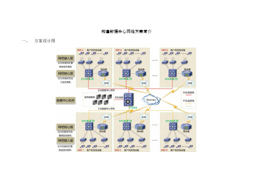
构建数据中心网络方案简介一、方案设计图二、方案介绍1.整个网络类似一个以数据中心机房为核心的城域网,各区域核心交换机直接连接数据中心机房交换机,同时数据中心交换机承载所有区域的数据服务业务,区域服务器全负载在数据中心交换机上。
各个区域拥有独立的一套网络构造:内部局域网(核心交换机接入交换机)和外部网络(路由器,宽带供应商)。
2.数据中心采用大容量万兆骨干核心路由交换机,此交换机系统的主控单元、电源等关键模块,采用的配备模块,保证数据中心的业务不中断。
拥有个业务板槽位,根据不同接入方式,有不同的选择。
在此网络中,配备个万兆业务板,最大扩展到个万兆端口,提供各区域的万兆网吧接入和数据中心服务器承载。
在配备块口光纤业务板,满足区域网络小型千兆网络接入。
3.各区域核心交换机分千兆数据专网接入和万兆数据专网接入。
所谓千兆数据专网接入是指些,区域较小,核心设备只拥有千兆光纤接口,连接数据中心交换机口千兆端口。
而万兆数据专网接入,则是针对区域网络业务较大,核心设备在拥有千兆网络接口的同时还少数万兆端口,能够用万兆介质来和数据中心相衔接。
4.数据中心机房中所有网络服务器采用万兆网卡接入网络,众所周知在现今网络服务器,在千兆网卡的使用情况下不能完全发挥出最佳性能。
数据中心服务器采用万兆网卡接入,更大程度回应各区域网络数据请求。
5.万兆业务板中万兆端口是类型,而区域核心交换机和服务器万兆网卡万兆端口全是类型,故选用不同类型的万兆模块。
再加之各区域和数据中心相距甚远,选用单模模块和光纤线;6.各区域网络构建中,万兆网络区域采用方案万兆核心,主干双千兆汇聚组网,千兆网络区域采用方案,千兆核心管理,主干双千兆汇聚组网;三、产品清单四、产品介绍、大容量万兆骨干核心路由交换机系列交换机在提供大容量、高性能的线速交换能力的基础上,进一步融合了硬件、、组播、、带宽控制、网络安全等智能业务特性,同时其采用了基于多处理器分布式处理机制和空分交换的体系结构,关键模块均采用冗余备份。
TG-NET软路由器快速配置向导
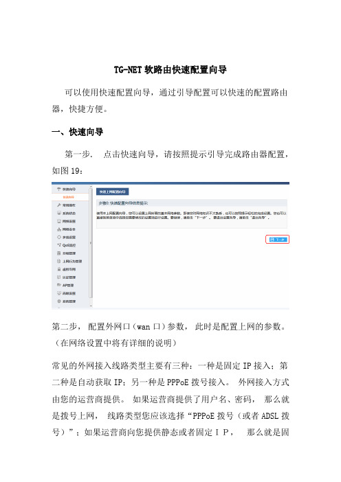
TG-NET软路由快速配置向导可以使用快速配置向导,通过引导配置可以快速的配置路由器,快捷方便。
一、快速向导第一步. 点击快速向导,请按照提示引导完成路由器配置,如图19:第二步,配置外网口(wan口)参数,此时是配置上网的参数。
(在网络设置中将有详细的说明)常见的外网接入线路类型主要有三种:一种是固定IP接入;第二种是自动获取IP;另一种是PPPoE拨号接入。
外网接入方式由您的运营商提供。
如果运营商提供了用户名、密码,那么就是拨号上网,线路类型您应该选择“PPPoE拨号(或者ADSL拨号)”;如果运营商向您提供静态或者固定IP,那么就是固定IP上网,线路类型您应该选择“固定IP“;如果运营商说插上网线就能用,那么就是DHCP上网,应该选择”自动获取IP“,下面将分别说明拨号上网注意事项:A).上网服务提供商(运营商)有中国电信、中国联通、中国移动、教育网、长城宽带,此项内容必须填写准确,如果分类中没有的,选择其他;B).上网类型以及带宽可根据上网服务提供商(运营商)给您提供的线路类型和带宽来选择,比如您如果选择了光纤10M,那么参考上行带宽和参考下行带宽会给出一个线路可用总带宽的参考值,该参考值将会被智能流控和多线策略所使用,所以必须填写准确。
如果下拉列表中没有的,请勾选自定义;由于上行、下行参考值会同步到智能流控的总带宽参数,所以会预留部分带宽用于防御突发数据,总带宽越小,预留越多,总带宽越大,预留越少。
上下行带宽建议设置为总带宽的0.9到0.95,预留部分带宽用于防御突发数据,带宽富裕的地区,可以设置高于0.95的系数。
上行、下行总带宽单位为千字节每秒,即KB/s, 一般是标称带宽乘以100来计算,比如10M 光纤,上下行总带宽是10*100,即1000KB/s,考虑预留一些带宽,推荐设置937KB/s。
一般而言,选择“上网类型以及带宽”,会自动填充“参考上行带宽”和“参考下行带宽“,系统会自动考虑预留并计算带宽。
TG云平台用户手册

TG云平台用户手册版权声明本手册中的所有内容及格式的版权属于深圳市万网博通科技有限公司(以下简称万网博通)所有,未经许可,任何人不得仿制、拷贝、转译或任意引用。
版权所有不得翻印© 2013 万网博通公司商标声明本手册中所谈及的产品名称仅做识别之用。
手册中涉及的其他公司的注册商标或是版权属各商标注册人所有,恕不逐一列明。
TG-NET® 万网博通公司信息反馈目录1概述 (3)2安装指南 (4)2.1安装环境 (4)2.1.1硬件环境 (4)2.1.2软件环境 (4)2.2软件安装 (4)2.3用户登录 (5)3主要功能 (6)3.1网络诊断 (6)3.1.1高危项目 (6)3.1.2风险项目 (6)3.1.3安全项目 (6)3.1.4提示项目 (7)3.2网络拓扑 (7)3.2.1星形拓扑 (7)3.2.2环形拓扑 (7)3.3设备管理 (8)3.3.1系统信息 (8)3.3.2端口统计 (8)3.3.3系统信息配置 (8)3.3.4端口配置 (8)3.3.5WEB管理 (9)3.4统计图表 (9)3.5系统状态 (9)3.6系统日志 (10)3.6.1管理日志 (10)3.6.2系统日志 (10)3.7系统设置 (11)3.7.1TNMP设置 (11)3.7.2账户设置 (11)3.7.3系统控制 (11)3.8安全退出 (11)1概述TG 云平台是面向中小型企业、网吧等网络用户,通过网络管理者对局域网内的网络设备进行集中式管理的软件系统。
TG 云平台适用于管理我司生产的所有智能管理型交换机产品,通过该软件可对中小型企业、网吧、行政机构等网络环境中的TG-NET网络设备进行全面的监控、管理、维护等一系列活动。
TG 云平台不仅涵盖了传统网管的基本功能,而且实时监控网络中所有交换机的运行状况,通过增加网络设备检测以及故障定位等功能,从而快速定位网络故障。
通过管理系统接口可直接访问网络中的设备,解决了网络设备因放置分散而导致管理难度加大的问题,从而减化了网络管理者对设备管理的复杂度。
TG-NET软路由上网基本设置

注意事项: 1. 上网服务提供商和带宽信息必须填写准确如果分类中没有的,勾选其他;(比如长城宽
带) 2. 上下行带宽建议设置为总带宽的 0.9 到 0.95,预留部分带宽用于防御突发数据,带宽富
裕的地区,可以设置高于 0.95 的系数。上行、下行总带宽单位为千字节每秒, 即 KB/s, 一般是标称带宽乘以 100 来计算, 比如 10M 光纤, 上下行总带宽是 10*100, 即 1000KB/s, 考虑预留一些带宽, 推荐设置 937KB/s。 一般而言, 选择“上网类型以 及带宽”, 会自动填充“参考上行带宽”和“参考下行带宽“,系统会自动考虑预留并 计算带宽。 只有找不到合适的类型时, 才需要进行自定义。 固定 ip
注意事项: 1. 上网服务提供商和带宽信息必须填写准确如果分类中没有的,勾选其他;(比如长城宽
带) 2. 上下行带宽建议设置为总带宽的 0.9 到 0.95,预留部分带宽用于防御突发数据,带宽富
裕的地区,可以设置高于 0.95 的系数。上行、下行总带宽单位为千字节每秒, 即 KB/s, 一般是标称带宽乘以 100 来计算, 比如 10M 光纤, 上下行总带宽是 10*100, 即 1000KB/s, 考虑预留一些带宽, 推荐设置 937KB/s。 一般而言, 选择“上网类型以 及带宽”, 会自动填充“参考上行带宽”和“参考下行带宽“,系统会自动考虑预留并 计算带宽。 只有找不到合适的类型时, 才需要进行自定义。 DHCP 上网
1、登陆路由器的 web 管理界面
1、1 windows xp 设置
鼠标右键点击桌面“网上邻居”图标,选择属性,打开‘网络连接’菜单, 如图 1 所示,(或者点击“开始-设置-网络连接”也可以打开,如图 2 所示)。
TG-NET 核心全万兆+主干20G汇聚网络解决方案

路由器
全千兆智能流控路由器
RN6000
CPU:1.8GHz网络处理器,二级缓存:1M,Memory:1G,Flash:1G,Wan口:5个,Lan口:1个,USB口:2个,Console口:1个,并发连接数:160000
核心交换机
全万兆三层核心交换机
S6500-24TF
24个SFP+万兆光口,背板带宽:650Gbps,转发速率:全线速过滤转发484Mpps;
3、其他特点:
1)、高性价比:TG-NET系列产品拥有完全的自主知识产权,在满足组网需求的前提下为网吧提供灵活的低成本网络解决方案,可确保您的网吧网络设备五年不落伍,避免重复投资的风险;
2)、速度快:采用全万兆汇聚组网后,最终将网络每24/48台共享20G网络带宽,保证网络核心服务数据流畅通无阻。
3)、维护易:所用网络产品都具有图形化、智能化、集中化、安全防御一体化的平台管理,结合TG-NET自助研发的TG云平台管理软件,构造一套让人省心、放心、舒心的网络环境。
全万兆三层核心交换机
S6500-24TF-2QF
24个SFP+万兆光口,1个扩展槽(2个40G QSFP+端口或8个万兆SFP+端口)背板带宽:650Gbps,转发速率:全线速过滤转发484Mpps;
接入交换机
万兆汇聚交换机
S4200-24G-2TF
24个10/100/1000M电口-2个SFP+万兆光口,默认25、26端口汇聚;背板带宽:88Gbps,转发速率:全线速过滤转发66Mpps;
3、交换机20G连接:接入交换机S4200系列和S6500全万兆三层核心交换机之间建立汇聚模式,使用2根万兆连接介质(万兆模块+光纤跳线),相互连接构成20G网络带宽;S4200系列万兆汇聚交换机剩余千兆电口,使用双绞线连接网络客户机终端,可以同时接入24/48台电脑终端;
- 1、下载文档前请自行甄别文档内容的完整性,平台不提供额外的编辑、内容补充、找答案等附加服务。
- 2、"仅部分预览"的文档,不可在线预览部分如存在完整性等问题,可反馈申请退款(可完整预览的文档不适用该条件!)。
- 3、如文档侵犯您的权益,请联系客服反馈,我们会尽快为您处理(人工客服工作时间:9:00-18:30)。
万兆网卡安装教程
1、无盘系统对网卡万兆支持情况
由于万兆网卡采用最新的INTEL82599ES芯片,目前国内各家无盘系统对芯片支持的版本不同。
WINDOWS版本的无盘系统:直接下载对应系统版本的驱动即可(驱动安装请参照相关教程,暂时不支持Windows Xp);
LINUX版本的无盘系统中:网众无盘需使用Linux 5.0.820以上内核才能驱动成功,信佑无盘需使用Linux 4.0的版本才能驱动成功。
LINUX无盘无需安装驱动,系统能自动识别。
2、硬件安装
X8DT6主板为例。
(PCI-E 即为普通PC机插显卡的插槽)
3、驱动安装
3.1根据无盘系统选择相应的驱动程序
3.1.1进入INTEL官网下载页面:
/default.aspx?lang=zho&iid=gg_support-cn+home_download
3.1.2选择INTEL 82599以太网控制器,如下图:
产品系列:选择以太网组件
产品线:选择以太网控制器
产品名称:选择82599万兆以太网控制器
3.1.3选择对应无盘系统的驱动程序,如下图:
3.1.4下面以2003系统为例,选择好我们要的系统版本后下面会出现符合要的驱动,点击下载。
根据我们系统是32位还是64位的下载我们需要的驱动。
点击下载后,出现页面会询问我们是否接受协议才能下载,点击接受后会弹出下载界面直接点保存就可以了,如果没弹出下载界面,请点重新启动重试。
3.2接下来我们找到存放下载文件的目录运行驱动安装文件来进行安装:
点击接受协议并点击下一步。
这里只需安默认选择,无需更改,然后点击下一步。
点击安装。
即开始自动安装驱动了
驱动安装完成后就能在设置管理器里面的网络适配器里面看到:
Intel(R)Ethernet Server Adapter X520-DA2 的硬件设备这样网卡驱动就安装完成。