Mechanics-ch03-00
YYC斜齿条样本

齿条rack 1
反向齿规 opposite tooth gauge 齿条rack 2
安装顺序1: 安装孔 assembly sequence 1:assembly bore
安装顺序2:固定销孔 assembly sequence 2:position pin
齒條型號說明 Rack Code Instruction
研磨 Ground
熱處理 With H
CHGH
S45C
斜齒 Helical
2,3,4,5,6,8
研磨 Ground
熱處理 With H
CSM
S45C
直齒 1,1.5,2,2.5,3,4,5,6,8 精铣
無
Straight
Milled Without H
CHM
S45C
斜齒 Helical
2,3,4,5,6,8
C3 Pitch Error
No.
/300mm
CSTGH 020 05 2 502.65 80 24 24 22 62.83 125.66 4 8 7 11 7 31.3 440.1 5.7 0.022
CSTGH 020 10 2 1005.31 160 24 24 22 62.83 125.66 8 8 7 11 7 31.3 942.7 5.7 0.022
2,3,4,5,6
研磨 Ground
熱處理 With H
CHGHL
S45C
斜齒 Helical
2,3,4,5,6
研磨 Ground
熱處理 With H
MSGHL
SCM440
直齒 Straight
2,3,4,5,6
研磨 Ground
熱處理 With H
07-Conformationaa_Anal-04[1]
![07-Conformationaa_Anal-04[1]](https://img.taocdn.com/s3/m/0631236ea98271fe910ef947.png)
ΔG = +3 kcal mol-1
Conformational Preferences: Acetaldehyde
staggered
Torsional Strain (Pitzer Strain): Ethane
eclipsed
A H O C H
H H
H O C H H H B
H CH2 C H H H H CH2 H
+2.0 kcal/mol
eclipsed conformation H
C H
Conformational Preferences 1-Butene (X = CH2); Propanal (X = O)
H
Wiberg K. B.; Martin, E. J. Amer. Chem. Soc. 1985, 107, 5035-5041.
Relevant Orbital Interactions:
H
Chem 206
Torsional Strain: the resistance to rotation about a bond Torsional energy: the energy required to obtain rotation about a bond Torsional Angle: also known as dihedral angle Torsional steering: Stereoselectivity originating from transition state torsional energy considerations
A
H Me X
A' C
H X
C
H X
C
Extech Instruments Model HT200 Heat Stress WBGT Me

USER GUIDEHeat Stress WBGT MeterModel HT200EXTECH INSTRUMENTS IntroductionThank you for selecting the Extech Instruments Model HT200 Heat Stress WBGT Meter. The HT200 accurately determines the Heat Stress by factoring a combination of parameters: Humidity, Temperature, and Direct Solar Radiation. These factors affect how high body temperatures rise, as well as the ability to cool down. This device is shipped fully tested and calibrated and, with proper use, will provide years of reliable service. Please visit our website () to check for the latest version of this User Guide, Product Updates, Product Registration, and Customer Support.Features∙Fast responding capacitance sensor∙Accurate measurements for: Wet bulb globe temperature (WBGT), Black globe temperature (TG), Humidity (%RH), Air temperature (TA), Wet bulb (WET), and Dew point (DEW)∙Maximum, minimum, and data hold Recording∙Low battery indication∙LCD display with LED backlighting∙Manual data recording (up to 50 reading sets)∙View data records∙Selectable temperature units C or F∙Brass black ball 50mm (2”) diameter∙WBGT high and low audible and visual alarm functions∙Auto Power OFF with disable functionSafetyWARNING: Avoid electromagnetic interference (EMI) to avoid erratic meter readings.WARNING: The measurements will be inaccurate if the black ball is touched during a test.WARNING: If the black ball is damage or deformed in shape, inaccurate measurement values will result.CAUTION: Please place the meter in a warm temperature and low humidity environment for 24 hours after the meter has been used in an overly humid environment.CAUTION: Please have the meter calibrated yearly for the best results.WARNING: Do not store this device in direct sunlight or in overly hot and/or damp areas.EXTECH INSTRUMENTS611Meter Description1. Up Arrow/MAX ‐MIN button2. MODE/SET button3. Power ON ‐OFF button4. UNIT/DATA HOLD button5. LCD Display6. Temperature & Humidity sensor7. Black Globe sensor8. Backlight/MEM button9. SEL/Alarm button 10. Down arrow/REC button 11.AC Adaptor power jackNote: Battery compartment on backLCD Display Description1.Alarm symbol2.DATA HOLD symbol3.WBGT Mode4.Max reading symbol5.Air temperature mode6.Black globe temperature mode7.MIN (minimum) reading symbol8.Wet bulb temperature modeB symbol (unused in HT200)10.Dew point temperature mode11.Primary display area12.Temperature units13.Relative humidity mode14.Secondary display area15.Stored reading ‘R’ alert & Memory Recall ‘M’ icon16.Time symbol (unused in HT200)17.Date symbol (unused in HT200)18.Data Record mode symbol19.Set Mode symbol20.Indoor symbol (WBGT)21.Outdoor symbol (WBGT)22.Low battery symbol23.Auto power off symbolOperationPowering the meterPress the Power button to power the meter ON or OFF. To show all of the display symbols at once: with the meter OFF, press and hold the Power button. The firmware version will display for one second (after the button is released).Auto Power OffThe HT200 automatically powers off after approximately 15 minutes of inactivity.Enable‐Disable Auto Power OffWith power ON, press and hold the Power button for at least 2 seconds to disable or enable auto power‐off. The clock symbol appears on the LCD screen when the Auto Power OFF feature is enabled. The symbol disappears when the Auto Power OFF feature is disabled. Note: The auto power‐off will be disabled if the SET function or the alarm is enabled.Alarm ON‐OFFPress and hold the SEL/Alarm button for at least 2 seconds to turn the alarm function ON (armed) or OFF (disarmed). When armed the ALARM display icon will appear. When disarmed, the ALARM display icon disappears.Note: The alarm function is disabled when the HOLD, SET, or VIEW DATA RECORDSD function is enabled.Display BacklightPress the Backlight/Mem button to turn on the LCD backlight. The LCD backlight will automatically turn off after 15 seconds.Selecting Temperature C/F units of measurePress the Unit/DH button to select the desired temperature unit of measure.Mode SelectionPress the Mode/Set button to change the mode. The available modes are WBGT, TA, %RH, TG, WET, DEW, and back to WBGT (see definitions below):o Wet bulb globe temperature (WBGT)o Air temperature (TA)o Humidity (%RH)o Black globe temperature (TG): monitors the effects of direct solar radiationo Wet bulb temperature (WET)o Dew point temperature (DEW)In the WBGT mode, press the Sel/Alarm button to toggle IN (indoor: without direct sun exposure) and OUT (outdoor: with direct sun exposure) modes.Note: The mode function is unavailable in the HOLD function and SET function modes.Data HoldPress and hold the Unit/DH button for 2 seconds to enable the Data Hold function. The HOLD display icon will appear the displayed reading will be frozen until the button is pressed and held again.Note: The HOLD function is unavailable when the SET function is enabled.Manual Data RecordingPress the REC button to manually record (store) the current reading. The REC and R symbol will briefly appear on the LCD while the reading is stored.Note: The Record Reading function is unavailable in the HOLD, SET, and VIEW DATA RECORDS modes.View Data RecordsPress and hold the Backlight/Mem button to turn access (or exit) the View Data Records mode. When the View Data Records mode is accessed, the record number is shown on the bottom of the display, the associated reading is shown at the center or the LCD, and the ‘M’ memory and ‘REC’ icons will be visible.Use the arrow buttons to scroll through the stored readings.Press the Mode/Set button to change the measurement type (i.e. WBGT, TA, %RH) for the currently selected record.Press the Unit/DH button to switch the temperature unit.Press and hold the Backlight/Mem button to exit the viewing data records mode.Note: The View Data Records mode is unavailable when the HOLD or SET function is enabled. Maximum‐Minimum (MAX‐MIN) Reading RecordingPress and hold the Max/Min button to enter the MAX‐MIN recording mode. The LCD will show the MAX icon along with the maximum temperature measurement.Use the Max/Min button to toggle between Maximum (MAX) and Minimum (MIN) readings. Press and hold the Max/Min button for more than 2 seconds to exit the maximum/minimum mode.Note: The MAX‐MIN mode is unavailable when the HOLD, SET, or VIEW DATA RECORDS function is enabled.Setting ModePress and hold the button to access the Setting mode where a series of parameters can be customized. The available parameters are explained individually below. To scroll through theparameters use the button. Press the button to start editing a particular parameter as explained below.WBGT HIGH ALARM THRESHOLD (HI)1.Step to the WBGT High Alarm Threshold screen using the button.2.At the High Alarm Threshold screen, press the button to begin editing; the displaywill begin flashing.3.Press the button to select the desired temperature units.e the up and down arrow buttons to set the WBGT High Alarm Threshold value.e the button to select the digit to edit.6.Press the button again to save the setting.7.The meter will now aurally and visually alarm when the High Alarm Threshold has beenexceeded. To arm/disarm the alarm function, refer to the ‘ALARM ON‐OFF’ section. WBGT LOW ALARM THRESHOLD (LO)1.Step to the WBGT Low Alarm Threshold screen using the button.2.At the Low Alarm Threshold screen, press the button to begin editing; the displaywill begin flashing.3.Press the button to select the desired temperature units.e the up and down arrow buttons to set the WBGT Low Alarm Threshold value.e the button to select the digit to edit.6.Press the button again to save the setting.The meter will now aurally and visually alarm when the Low Alarm Threshold is reached. To arm/disarm the alarm function, refer to the ‘ALARM ON‐OFF’ section.CLEAR STORED READINGS1.Step to the ‘Clear Stored Reading’ screen (example shown above) using the button.The number at the bottom of the display indicates the number of readings stored (50 maximum).2.Press the button and the display will begin flashing.e the up or down arrow button to select YES or NO. Select YES to erase all storedreadings. Press NO to retain the readings in memory.4.Press the button to perform the selected action (YES or NO).AIR TEMPERATURE OFFSET1.Step to the Air Temperature Offset screen using the button (example screen shownabove).2.Press the button to begin editing; the display will begin flashing.e the up and down arrow buttons to set the offset value (from ‐9.9 to +9.9)4.Press the button to select the desired temperature units.5.Press the button again to save the setting.RELATIVE HUMIDITY % OFFSET1.Step to the RH% Offset screen using the button (example screen shown above).2.Press the button to begin editing; the display will begin flashing.e the up and down arrow buttons to set the offset value (from ‐9.9 to +9.9).4.Press the button again to save the setting.BLACK GLOBE TEMPERATURE OFFSET1.Step to the Black Globe Temperature Offset screen using the button (examplescreen shown above).2.Press the button to begin editing; the display will begin flashing.e the up and down arrow buttons to set the offset value (from ‐9.9 to +9.9).4.Press the button to select the desired temperature units.5.Press the button again to save the setting.Battery ReplacementWhen the battery icon () appears on the LCD, the 9V battery must be replaced. Turn off the power and unplug all cables. Remove the battery from the rear battery compartment and replace it with a new 9V battery. Please observe correct battery polarity and do not switch the unit ON until the battery door is closed and secured.When the meter is not in use, please remove the battery.Never dispose of used batteries or rechargeable batteries in household waste.As consumers, users are legally required to take used batteries to appropriatecollection sites, the retail store where the batteries were purchased, or whereverbatteries are sold.Disposal: Do not dispose of this instrument in household waste. The user is obligated to take end‐of‐life devices to a designated collection point for the disposal of electrical and electronic equipment.AC Adaptor PowerThe AC power adaptor jack is located on the bottom of the meter. See specifications below:External AC to DC adapter: Voltage 9 V DC (8~14 V DC Max) / 500mW.Socket: Pin positive, Ground casing negative.External diameter 5.5mm internal diameter 2.1mmSpecificationsWet bulb globe temperature (WBGT)Unit Range ResolutionAccuracy @15~40 o CIndoor& Outdoor Withoutsunlight °C 0~59.0 0.1 ±1.0 °F 32.0~ 138.0 0.1 ±1.8Outdoor With sunlight°C 0~56.0 0.1 ±1.5 °F 32.0~ 132.0 0.1 ±2.7Indoor & Outdoor without sunlight:WBGT = (0.7×WET)+(0.3×TG)Outdoor with sunlight:WBGT=(0.7×WET)+(0.2×TG)+(0.1×TA)Air Temperature (TA)Unit Range Resolution Accuracy @15~40o C°C 0~50.0 0.1 ±0.8°F 32.0~122.0 0.1 ±1.5Black globe temperature (TG)Unit Range Resolution Accuracy @15~40 o C °C 0~80.0 0.1 ±0.6°F 32.0~176.0 0.1 ±1.1Relative Humidity (%RH)Measurement Range 1%~99%Accuracy ±3.0%RH (20~80%)±5.0%RH (<20% or >80%)Resolution 0.1%Dew point temperature (DEW)Unit Range Resolution°C ‐35.3~48.9 0.1°F ‐31.5~120.1 0.1The value is calculated from the RH and Air temperatureWet bulb temperature (WET)Unit Range Resolution°C ‐21.6~50.0 0.1°F ‐6.9~122.0 0.1The value is calculated from the RH and air temperatureMeter Dimensions300 x 70 x 50mm (11.81 x 2.76 x 1.97in.) [L x W x H]LCD 52 mm (W) x 36mm (L) [2.05 in (W) x 1.42 in (L)]Ball Dimensions 50mm diameter, 19mm height (2” diameter and 0.75” height)Weight 220g (7.76oz.) without batteriesOperating Altitude 2000m (6562ft) max.Sampling Rate One per second (1 Hz)Operating Temperature & Humidity 0°C to +50°C (32°F to 122°F), <95%RH. (Non‐condensing) Storage Temperature & Humidity ‐10°C to +50°C (14°F to 122°F), <70% RH. (Non‐condensing) Power supply 9V battery or AC Adaptor 100~240V DC 9V/ 0.5A (9mm)Battery life 200 hoursAccessories 9V battery, Carrying Case, and AC100~240V to DC 9V/0.5A (9mm) AdaptorThermal Hazard Prevention StandardsScreening Criteria for Heat Stress Exposure (WGBT values in °C); for reference purposes only.Example of Activities within Metabolic Rate Categories*Categories Examples/ActivitiesResting Sitting quietlySitting with moderate arm movementsLight Sitting with moderate arm and leg movements Standing with lightwork at machine or bench while using mostly arms Using a table sawStanding with light or moderate work at a machine or bench and some walking aboutModerate Scrubbing in a standing positionWalking about with moderate lifting or pushingWalking level at 3.7 mph (6Km/hr) while carrying 6.6 lbs. (3 Kg) weightHeavy Carpenter sawing by handShoveling dry sandHeavy assembly work on a non‐continuous basisIntermittent heavy lifting with pushing/pulling (pick‐and‐shovel work)Very heavy Shoveling wet sand*According to the American Conference of Governmental Industrial Hygienists [ACGIH] (2005)Copyright © 2015 FLIR Systems, Inc.All rights reserved including the right of reproduction in whole or in part in any form。
美国麦克尼安机械与工具公司产品维修部件手册说明书

3655-251-0003/2011Please read and save this Repair Parts Manual. Read this manual and the General Operating Instructions carefully before attempting to assemble,install, operate or maintain the product described. Protect yourself and others by observing all safety information. The Safety Instructions are contained in the General Operating Instructions. Failure to comply with the safety instructions accompanying this product could result in personal injury and/or property damage! Retain instructions for future reference . AMT reserves the right to discontinue any model or change specifications at any time without incurring any obligation.©2006 American Machine & Tool Co., Inc. of PA, A Subsidiary of The Gorman-Rupp Company, All Rights Reserved.Periodic m aintenance and inspection is required on all pum ps to insure proper operation. Unit m ust be clear of debris and sedim ent. Inspect for leaks and loose bolts. Failure to do so voids warranty.SELF-PRIMING SPRINKLER/BOOSTER PUMPSRefer to pump manual 1808-634-00for General Operating and Safety Instructions.DescriptionThese self-priming (to 20 ft. lift) lawnsprinkler pumps are equipped with a check valve to assist in positive priming, a high performance closed impeller, a Buna-N mechanical seal to prevent leakage, and a continuous duty motor.Pumps are designed for higher pressure applications such as lawn sprinkling,spraying irrigation, also draining andgeneral de-watering applications. Casing working pressure to 150 psi (1034 kPa).Handles fluids from 40º to 180º F (4º to 82ºC). For use with nonflammable, non-abrasive liquids compatible with pump component materials.MaintenanceMake certain that this unit isdisconnected frompower source before attempting to service or remove any component!MECHANICAL SEAL REPLACEMENT Refer to Seal Replacement figures 2, 3. IMPORTANT: Always replace both seal seat (Ref. No. 6) and seal head (Ref. No. 7)to insure proper mating of components!Also, impeller seal (Ref. No. 22) (where applicable) should be replaced anytime impeller fastener (Ref. No. 23) has been removed.1.Unthread fasteners (Ref. No. 16) and remove pump casing (Ref. No. 14),casing seal (Ref. No. 5), and flapper valve (Ref. No. 13) from adapter (Ref.No. 4).2.Unthread fasteners (Ref. Nos. 12 and 17) and remove volute (Ref. No. 10)from adapter.3.Remove impeller fastener, impeller seal (where applicable), and impeller (Ref. No. 9).4.Shaft sleeve (Ref. No. 21) (where applicable) and seal head can now be pulled from shaft.IMPORTANT: Care should be taken to insure that the same number of shim washers (Ref. No. 8) are replaced behind impeller as were removed. These shim washers are located directly behindimpeller. These washers as well as impeller key (Ref. No. 24) (where applicable)become loose as impeller is removed.NOTE: Some motors (Ref. No. 20) use an open end 7/16" wrench across flats on rear of motor shaft (remove bearing cap foraccess) to prevent shaft from turning. Othermotor shafts have a screwdriver slot instead of flats.5.Unscrew fasteners (Ref. No. 23). Remove mounting base and handle (Ref. No. 18 &2) (where applicable), and adapter from motor mounting face.6.Push seal seat from back of adapter recess with a screwdriver.7.Clean adapter recess before inserting a new seal seat.The precision lapped faces on mechanical seal are easily damaged.Handle your replacement seal carefully.8.Carefully wipe polished surface of new seal seat with a clean cloth.9.Wet rubber portion of seal seat with a light coating of soapy water.10.Press new seal seat squarely into recessin adapter. If seal seat does not press squarely into cavity, it can be adjusted in place by pushing on it with a piece of pipe. Always use a piece of cardboard between pipe and seal seat to avoid scratching polished surface.11.After seal seat is in place, ensure that it isclean and has not been marred.NOTE: If removed, slide slinger washer (Ref.No. 1) onto shaft until it is located approxi-mately 1/8" from face of motor bearing hub.ing a clean cloth, wipe shaft/shaftsleeve and make certain that it is perfectly clean.13.Secure foot and handle (where applicable)and adapter on motor mounting face.Carefully guide motor shaft through seal seat.14.Replace shaft sleeve and impeller key(where applicable).IMPORTANT: Before installing new shaftsleeve, apply a bead of non-hardening, pliable sealant (such as Permatex® Form-A-Gasket®No. 2) to motor shaft shoulder.15.Wet inside rubber portion of new seal headwith a light coating of soapy water. Slide head onto shaft/shaft sleeve. Seal head and seal seat will meet. Reinstall any shims which have been removed. (See Shim Adjustment).16.Install impeller and reassemble pump.17. A short "run-in" period may be necessaryto provide completely leak-free seal operation.SHIM ADJUSTMENT (365 SERIES ONLY)When installing a replacement impeller (Ref.No. 9) or motor (Ref. No. 20), it may benecessary to adjust number of shims (Ref. No.8) to insure proper running clearance between impeller and volute (Ref. No. 10). Proceed as follows:NOTE: A proper running clearance is less than 0.010" (face of impeller to mating face of volute).1.For impeller replacement, add one (0.010")shim in addition to those removed originally.2.For motor replacement, add two (0.010")shims in addition to those removed during disassembly.3.Reassemble the pump as described in steps 16 and 17 (above).IMPORTANT: Ensure that volute is snugly in place and check shaft to make sure it is turning freely (use 7/16" wrench or screwdriver to turn shaft). If it turns freely, check to ensure that adapter (Ref. No. 4) and volute are fitted metal-to-metal where they meet on outside. If they are not metal-to-metal, tighten fasteners (Ref. No.12 & 17) and recheck shaft for free turning.Tighten carefully, turning shaft while tightening so that motor bearings are not damaged in the event that too many shims were installed. If shaft seizes before fasteners are completelytight, disassemble pump and remove one (0.010") shim and repeat reassembly.4.When proper clearance is obtained,reassemble.3655-95 thru 3657-95 and S pecifications Information and Repair Parts Manual 3790-95 thru379L-95 Please provide following information:-Model number-Serial number (if any)-Part descriptions and number as shown in parts listRepair Parts List3790 (3/4 HP)3791 (1 HP)3792 (1½ HP)3793 (2 HP)379G (3/4 HP)379H (1 HP)3797 (1½ HP)379K (2 HP)379A (1 HP)379B (1½ HP)379C (2 HP)379D (3 HP)3657 (5 HP)Description379F (1 HP)379J (1½ HP)379E (2 HP)379L (3 HP)3655 (5 HP)3656 (7½ HP)Qty.1Slinger washer1534-000-001534-000-001534-000-001534-000-001470-093-001470-093-001 2Handle1515-000-001515-000-001515-000-001515-000-00 -- -- 1 3Fastener******4 4Adapter1608-011-011608-011-011608-011-011608-011-013655-030-093655-030-091 5Casing Seal - Buna N (std)1610-000-001610-000-001610-000-001610-000-002186-000-002186-000-001 - Viton (opt)1610-001-001610-001-001610-001-001610-001-002186-001-002186-001-006 & 7† Shaft seal assy. -Buna N (std)1640-161-961640-161-961640-161-961640-161-961640-163-901640-163-901† - Viton (opt)1640-161-971640-161-971640-161-971640-161-971640-163-911640-163-91 8Impeller Shim pkg. -- -- -- -- 1664-000-901664-000-901 9Impeller379A-011-09379B-011-09379C-011-09379D-011-093655-012-093656-012-091 10Volute379B-150-09379B-150-09379D-150-09379D-150-093655-150-093655-150-091 11Washer******2 12Fastener******2 13Flapper valve -Buna N (std)1609-002-001609-002-001609-002-001609-002-001609-002-001609-002-001 -Viton (opt)1695-011-901695-011-901695-011-901695-011-901695-011-901695-011-90 14Casing2111-001-012111-001-012111-001-012111-001-012112-001-022112-001-021 15Pipe plug******2 16Fastener******4 17Fastener******1 18Foot1506-000-001506-000-001506-000-001506-000-00 -- -- 1 19Fastener******1 20Motor - 1 Phase ODP1626-010-001626-011-001626-012-001626-024-00 -- --1 - 3 Phase ODP1626-014-001626-015-001626-016-001626-025-00 -- --- 1 Phase TEFC1626-069-001626-050-001626-070-001626-071-001626-078-00 --- 3 Phase TEFC1626-077-001626-053-001626-054-001626-072-001626-044-001626-045-00 21Shaft sleeve -- -- -- -- 1472-000-001472-000-001 22Impeller seal -- -- -- -- 1471-020-001471-020-001 23Impeller fastener1784-001-091784-001-001784-001-001784-001-001756-000-001756-000-001 24Impeller key -- -- -- -- 1471-030-001471-030-001 (*)Standard hardware item, available locally(†)Seal head (Ref. No. 7) and seat (Ref. No. 6) available as a set only. When replacing a shaft seal assembly, a new impeller seal (Ref. No. 23) should also be used. (Model series 365 only).-2-。
沃尔斯全部产品介绍
沃尔斯全部产品介绍一、发动机油(一)柴机油系列1沃尔斯抗磨宝(工程机械专用):品牌:volks型号:CG—4、CH—4、CI—4规格:18L【产品说明】●采用优质基础油加入进口添加剂,具有抗磨损、抗氧化、抗腐蚀及抗泡沫性能,满足多种工业用途。
●具有优异的热稳定性,满足较高的操作温度及重负荷条件下使用。
●精选优质抗磨损添加剂,可为工程机械在苛刻的操作条件下,提供有效的抗磨损保护。
●具有卓越的过滤能力,防止细微过滤器出现过早闭塞的现象。
●具有优越的空气释放性及抗泡沫性能,可防止气穴腐蚀的产生。
●产品优异性能及品质可替代同类进口产品。
【贮藏方法】密封、置阴凉干燥处。
【注意事项】①禁止吸入,避免长期或反复与皮肤接触。
②禁止储存在超高温环境中。
③请保护环境,勿随意丢弃废油及包装。
【执行标准】GB11118.1-94适用范围:●适用于工程、建筑、矿山、轧钢、塑料机械等中、高压液压系统。
●适用于高温、高速和重负荷的叶片泵、柱塞泵、齿轮泵的液压系统。
●适用于治金机械(如轧钢机、锻压机等),引进设备和车辆的液压系统。
●本品是HL液压油替代品,适用于各种进口、国产机床液压系统。
2沃尔斯油压宝品牌:volksCF-4、CH-4、CI-4规格:4L本产品符合美国石油学会API质量标准。
本产品采用优质基础油与原装进口复合添加剂精心调配而成,添加特殊的抗磨剂有效减少机件磨损,可延长国Ⅲ、国Ⅳ发动机换油周期,减少发动机的使用成本。
●采用独特的抗氧、抗磨、高碱值配方,减少部件磨损,延长换油周期,降低成本。
●低温启动顺畅,高温油膜坚固,即使在重载寒冬等严苛工况下,都能保持润滑性能,防止磨损。
●优异的清净分散性,防止活塞环的粘结及体内积碳的沉积。
●良好的抗锈蚀性能,强力增溶积碳漆膜和油泥,保护机件不受损坏。
●油膜承载能力强,能够良好的密封燃烧室,提高发动机功率,帮助节省燃油。
【贮藏方法】密封、置阴凉干燥处。
【注意事项】①禁止吸入,避免长期或反复与皮肤接触。
Cyclo 减速机

ᴎᑻো㣗ೈ
ǂ㑻
ǂ㑻
6060
6060DA
6275
6275DA
lj⊼ᛣџ乍NJ
Ƶ啓䕂⬉ᴎϢޣ䗳ᴎⱘՓ⫼䇋ᅝᥦ᪡❳㒗ⱘҎਬ䖯㸠DŽ Փ⫼ࠡ䇋Ҩ㒚䯙䇏Փ⫼䇈ᯢкDŽ
Ƶ䇋ᇚℸՓ⫼䇈ᯢк䗕ࠄᅲ䰙Փ⫼㗙ⱘЁDŽ Ƶ䇋ཹֱㅵℸՓ⫼䇈ᯢкDŽ
๑ᆩຫກ No.CM2001C-8 ᑈ᳜ॄࠋ
03
05
08
1
1H
2
3
4
5
4极 kW(HP) 0.1(1/8) 0.2(1/4) 0.25(1/3) 0.4(1/2) 0.55(3/4) 0.75(1) 1.1(1.5) 1.5(2) 2.2(3) 3.0(4) 3.7(5)
功率代号
8
10
15
20
25
30
40
50
60
75
100
kW(HP) 5.5(7.5) 7.5(10) 11(15) 15(20) 18.5(25) 22(30) 30(40) 37(50) 45(60) 55(75) 75(100)
环境温度1050353050科斯莫石油科斯莫齿轮se68科斯莫齿轮se100150科斯莫齿轮se220320460新日本石油bonnoc68bonnoc100150bonnoc黛芬妮超级齿轮油daphnesupergear68黛芬妮超级齿轮油daphnesupergear100150昭和壳牌石油可耐压omala极压齿轮润滑油68可耐压omala极压齿轮润滑油100150可耐压omala极压齿轮润滑油220460埃克森美孚事必达spartanep68事必达spartanep100150事必达spartanep220460美孚齿轮油600xp68美孚齿轮油600xp100150美孚齿轮油600xp220460jomo工业齿轮reductus68jomo工业齿轮reductus100150jomo工业齿轮reductus220460表18推荐润滑油工业用极压齿轮油sp系相当于jisk2219的2类工业用齿轮油在冬季或者环境温度比较低的地方使用时请使用表内的低粘度油
使用mach3,200w直流主轴电机--安装培训教程

安装培训教程声明:本雕刻机作为网络交流的个人作品,成品及半成品及套件并非严格意义上的商品,使用者需具备相关知识,凡是涉及机械、电子、计算机的设备都有可能因使用不当或病毒、与其它软件兼容原因等造成故障,此故障可能造成一定的危险及经济损失,本人不对直接及间接损失承担相应责任。
有关软件版权:本机器所涉及的相关软件均来自互联网,原作者享有版权,作为学习了解之用请及时删除并购买授权软件,使用没有授权的软件造成一切损失及法律问题由使用者自行承担。
有关培训范围:本人只对CNC雕刻机承担相应的责任,货款只是设备本身的价格未包含任何软件及软件培训费用,货到后用户在手册指导或通过网络在作者指导下设备调试成功即确认作者的工作完成,本设备使用过程中所涉及到的所有软件不在作者的培训责任之内,作者只能给予适当知道及在自己则能力之内给予答疑解惑网络时代请广大玩家尽量利用网络工具求助交流设备及软件的安装及设置警告:数控雕刻机是依靠相关软件控制工作的,设备上的一些安全触发装置也是依靠正确的软件设置才能正常运行,在没有完全确认设置正确的情况下冒然装刀试机可能都设备造成永久的损伤!本设备采用计算机并行接口和PC连接,控制软件MACH3通过并口端口控制雕刻机各轴按照指令运行WINDOWS请用sp2版本,其他版本可能出问题提示:并口(打印口)要求工作在EPP模式,任何其它模式可能造成雕刻机不能正常运行,有关EPP模式的设置应在计算机主板BIOS中进行,各个厂家的设置方法不尽相同,请参阅计算机的说明书进行设置。
(开机后按“Del”键进入BIOS,菜单中选择“CHIPSET FEATURES SETUP”,找到并口模式设置界面。
不同电脑的菜单界面有所不同,如果“CHIPSET FEATURES SETUP”中没有并口模式,挨个菜单进去看看,肯定能找到。
此方法台机主板可行,如果是卡的话就有分别了。
市场上低于300块的,都采用自适应,无法更改。
溶剂的化学位移(氢谱)
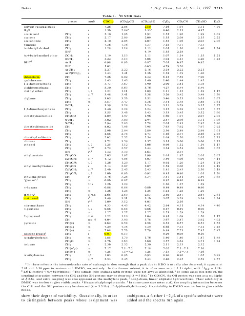
show their degree of variability.Occasionally,in order to distinguish between peaks whose assignment was ambiguous,a further 1-2µL of a specific substrate were added and the spectra run again.Table 1.1HNMR Data2acetic acid CH 3s 2.10 1.96 1.91 1.55 1.96 1.99 2.08acetoneCH 3s 2.17 2.09 2.09 1.55 2.08 2.15 2.22acetonitrile CH 3s 2.10 2.05 2.07 1.55 1.96 2.03 2.06benzeneCH s 7.367.367.377.157.377.33tert -butyl alcoholCH 3s 1.28 1.18 1.11 1.05 1.16 1.40 1.24OH c s 4.19 1.55 2.18tert -butyl methyl etherCCH 3s 1.19 1.13 1.11 1.07 1.14 1.15 1.21OCH 3s 3.22 3.13 3.08 3.04 3.13 3.20 3.22BHT bArH s 6.98 6.96 6.877.05 6.97 6.92OH c s 5.01 6.65 4.79 5.20ArCH 3s 2.27 2.22 2.18 2.24 2.22 2.21ArC(CH 3)3s 1.43 1.41 1.36 1.38 1.39 1.40chloroform CH s 7.268.028.32 6.157.587.90cyclohexaneCH 2s 1.43 1.43 1.40 1.40 1.44 1.451,2-dichloroethaneCH 2s 3.73 3.87 3.90 2.90 3.81 3.78dichloromethane CH 2s 5.30 5.63 5.76 4.27 5.44 5.49diethyl etherCH 3t,7 1.21 1.11 1.09 1.11 1.12 1.18 1.17CH 2q,7 3.48 3.41 3.38 3.26 3.42 3.49 3.56diglymeCH 2m 3.65 3.56 3.51 3.46 3.53 3.61 3.67CH 2m 3.57 3.47 3.38 3.34 3.45 3.58 3.61OCH 3s 3.39 3.28 3.24 3.11 3.29 3.35 3.371,2-dimethoxyethane CH 3s 3.40 3.28 3.24 3.12 3.28 3.35 3.37CH 2s 3.55 3.46 3.43 3.33 3.45 3.52 3.60dimethylacetamideCH 3CO s 2.09 1.97 1.96 1.60 1.97 2.07 2.08NCH 3s 3.02 3.00 2.94 2.57 2.96 3.31 3.06NCH 3s 2.94 2.83 2.78 2.05 2.83 2.92 2.90dimethylformamideCH s 8.027.967.957.637.927.977.92CH 3s 2.96 2.94 2.89 2.36 2.89 2.99 3.01CH 3s 2.88 2.78 2.73 1.86 2.77 2.86 2.85dimethyl sulfoxideCH 3s 2.62 2.52 2.54 1.68 2.50 2.65 2.71dioxane CH 2s 3.71 3.59 3.57 3.35 3.60 3.66 3.75ethanolCH 3t,7 1.25 1.12 1.060.96 1.12 1.19 1.17CH 2q,7d 3.72 3.57 3.44 3.34 3.54 3.60 3.65OH s c,d 1.32 3.39 4.63 2.47ethyl acetate CH 3CO s 2.05 1.97 1.99 1.65 1.97 2.01 2.07C H 2CH 3q,7 4.12 4.05 4.03 3.89 4.06 4.09 4.14CH 2C H 3t,7 1.26 1.20 1.170.92 1.20 1.24 1.24ethyl methyl ketone CH 3CO s 2.14 2.07 2.07 1.58 2.06 2.12 2.19C H 2CH 3q,7 2.46 2.45 2.43 1.81 2.43 2.50 3.18CH 2C H 3t,7 1.060.960.910.850.96 1.01 1.26ethylene glycol CH s e 3.76 3.28 3.34 3.41 3.51 3.59 3.65“grease”f CH 3m 0.860.870.920.860.88CH 2br s 1.26 1.29 1.36 1.27 1.29n -hexane CH 3t 0.880.880.860.890.890.90CH 2m 1.26 1.28 1.25 1.24 1.28 1.29HMPA g CH 3d,9.5 2.65 2.59 2.53 2.40 2.57 2.64 2.61methanolCH 3s h 3.49 3.31 3.16 3.07 3.28 3.34 3.34OH s c,h 1.09 3.12 4.01 2.16nitromethane CH 3s 4.33 4.43 4.42 2.94 4.31 4.34 4.40n -pentane CH 3t,70.880.880.860.870.890.90CH 2m 1.27 1.27 1.27 1.23 1.29 1.292-propanol CH 3d,6 1.22 1.10 1.040.95 1.09 1.50 1.17CH sep,6 4.04 3.90 3.78 3.67 3.87 3.92 4.02pyridineCH(2)m 8.628.588.588.538.578.538.52CH(3)m 7.297.357.39 6.667.337.447.45CH(4)m 7.687.767.79 6.987.737.857.87silicone grease iCH 3s 0.070.130.290.080.10tetrahydrofuran CH 2m 1.85 1.79 1.76 1.40 1.80 1.87 1.88CH 2O m 3.76 3.63 3.60 3.57 3.64 3.71 3.74tolueneCH 3s 2.36 2.32 2.30 2.11 2.33 2.32CH(o/p )m 7.177.1-7.27.187.027.1-7.37.16CH(m )m 7.257.1-7.27.257.137.1-7.37.16triethylamineCH 3t,7 1.030.960.930.960.96 1.050.99CH 2q,72.532.452.432.402.452.582.57aIn these solvents the intermolecular rate of exchange is slow enough that a peak due to HDO is usually also observed;it appears at 2.81and 3.30ppm in acetone and DMSO,respectively.In the former solvent,it is often seen as a 1:1:1triplet,with 2J H,D )1Hz.b 2,6-Dimethyl-4-tert -butylphenol.c The signals from exchangeable protons were not always identified.d In some cases (see note a ),the coupling interaction between the CH 2and the OH protons may be observed (J )5Hz).e In CD 3CN,the OH proton was seen as a multiplet at δ2.69,and extra coupling was also apparent on the methylene peak.f Long-chain,linear aliphatic hydrocarbons.Their solubility in DMSO was too low to give visible peaks.g Hexamethylphosphoramide.h In some cases (see notes a ,d ),the coupling interaction between the CH 3and the OH protons may be observed (J )5.5Hz).i Poly(dimethylsiloxane).Its solubility in DMSO was too low to give visible peaks.Notes.Chem.,Vol.62,No.21,19977513乙酸丙酮乙腈叔丁醇叔丁基醚氯仿二氯甲烷DMF三乙胺 硅脂四氢呋喃DMSO 乙醚甲醇。
- 1、下载文档前请自行甄别文档内容的完整性,平台不提供额外的编辑、内容补充、找答案等附加服务。
- 2、"仅部分预览"的文档,不可在线预览部分如存在完整性等问题,可反馈申请退款(可完整预览的文档不适用该条件!)。
- 3、如文档侵犯您的权益,请联系客服反馈,我们会尽快为您处理(人工客服工作时间:9:00-18:30)。
在17世纪,伽利略(Galileo)和牛顿(Isaac Newton)回 答了这些问题:
• 运动的起因是力: 力(Force): 物体间的相互作用 (对物体的推或拉).
•力对物体运动的影响由牛顿运动定律描述 牛顿力学
2009年10月14日 8:00-9:50
第三章 动量.牛顿运动定律.动量守恒定律
3
到目前为止:
质点的运动学:
利用质点的位置、速度和加 速度描述质点的运动,不 涉及运动的原因。
在本章中: 质点的动力学:
讨论运动的原因
2009年10月14日 8:00-9:50
第三章 动量.牛顿 动量•牛顿运动定律•动量守恒定律 古代的哲学家曾对物体的运动感到困惑:
• 物体的运动需要一个起因吗? • 如果需要,这个起因的本质是什么?
第三章 动量.牛顿运动定律.动量守恒定律
4
第三章 动量•牛顿运动定律•动量守恒定律
质点 经典力学 质点系
刚体
运动学
绝对运动 相对运动
力-质量-加速度方法
动力学 功-能方法
静力学
冲量-动量方法
2009年10月14日 8:00-9:50
第三章 动量.牛顿运动定律.动量守恒定律
5
第三章 动量•牛顿运动定律•动量守恒定律 图解经典力学:
力的定律
周围物体
力
物体
运动定律
加速度
• 力的定律(The force law): 如何计算作用在一个物体上 的力.
• 运动定律(The laws of motion) : 在力的作用下物体的 运动状态是如何改变的.
2009年10月14日 8:00-9:50
力学(Mechanics)
第三章 动量•牛顿运动定律•动量守恒定律
Momentum • Newton’s law of motion • Law of momentum conservation
2009年10月14日 8:00-9:50
第三章 动量.牛顿运动定律.动量守恒定律
1
第三章 动量•牛顿运动定律•动量守恒定律