AUTOMAT ULTRA系列光电自准直仪用户手册_REV.D
激光准直仪操作规程

激光准直仪操作规程激光准直测量系统由半导体激光器、光学分光及转向系统、光电接收系统及液晶显示模块组成。
激光光束经转向系统后出射两条相互平行的基准光束,作为导轨的安装检测基准。
该系统利用二维PSD作为光电接收器件,采用液晶显示模块显示导轨偏差,可快速、直接、准确地测量导轨安装的偏移量,从而提高导轨安装的精度和速度。
实验结果显示测量系统在X,Y方向上的标准偏差分别为:0.002mm,0.005mm。
1、主要参数2、主机由半导体激光器、空间位相调制器、壳体、底座、和电源所组成。
3、激光准直仪的特点与工作原理1)仪器的特点是采用了空间位相调制器。
激光束在任意测距上,其横截面均为一组良好的、红黑反差很大的同心圆环,中心光斑亮且小,利于定位。
而且在不同测距进行测量时是不用调焦的,实现了无调焦运行差。
中心光斑直径随着工作距离的增大而增大,符合下列参数:L=2.5米时Ø0.1mmL=20米时Ø1.2mmL=50米时Ø2.5mm2)将仪器固定在主机的回转轴上后用百分表测量仪器端部的测环在盘车处于不同位置时的差值,通过调整仪器底座上的调整螺钉,使其差值越来越小,只要主机轴系配合良好,可以调至±0.02~0.03mm。
然后利用置于远离主机15米左右的平面反射镜,将仪器射出的激光束反射至位于仪器附近的测微光靶。
在主机盘车时调整仪器壳体上的四只调整螺钉,(必要时适当调整反射镜的角度),使反射回来的激光束画的圆的半径越来越小,最后调至±0.1mm以内为止,此时应再次检查盘车360°时,百分表所显示波动值的范围和测微光靶的测量差值,准确无误时即可用此光轴代替主机的机械轴。
3)二维测微光靶二维测微光靶是用来记录与测量主机盘车时光轴的变化量。
二维测微光靶是由光靶和在X、Y两个自由度上测微的百分表所组成,光靶本身带有卡具和折射棱镜,为安装和读数提供了方便条件。
测微光靶的工作范围是±4.5mm。
自直准仪

图8 图6
图9 6
2) 假设通过移动测试表面,十字线处于图 10 所示的 位置,即其水平线介于垂直刻度线 23 和 24 之间, 并且其垂直线介于水平刻度线 21 和 22 之间。请 注意,反光镜的倾斜方向与十字线的移动保持一 致,朝向固定的刻度线。 现在开始测量分度值,请旋转测微计螺丝两次。 第一次旋转测微计螺丝将垂直十字线移动至距其最 近的刻度线 21,读取测微计上的刻度。然后在将测 微计复位至 0 后,再次转动测微计螺丝,将水平十 字线移动至距其最近的刻度线 23,读取测微计上 的刻度(如图 11 和 12 所示)。在本例中测微计上 的刻度分别为 21.5′′ 和 45′′。 请注意,水平和垂直刻度线上的一个刻度表示 1′, 而测微计上则相应表示 0.5′′。
斜制动,改变镜筒的倾斜度,使得镜筒与其在反光
镜内的图像看起来几乎对齐。(图 4)
4
旋转制动
水平行程手轮 倾斜制动
图4 (注) 如果因为反光镜表面太小而无法立即显示镜筒反射的图
像,请转动水平行程手轮横向移动镜筒,直至图像出现在 反光镜中。在这种情况下,请在完成上述对齐后,将镜筒 朝向反光镜中心位置移回。 4) 接着,请拧松旋转制动,并且透过目镜观看,向左、 右缓慢摆动自准直仪镜筒。通过执行此操作,十字 线图像将在视场内出现。当十字线在视场内可见 时,请停止摆动。拧紧旋转制动。 5) 最后,转动微调螺丝,使得十字线中心靠近垂直和 水平刻度在 15′ 线的交叉处。 为了便于日后的测量工作,建议您此时将测微计刻 度设置为 0。
1. 放置 ………………………………………… 4 2. 安装 ………………………………………… 4 Ⅲ. 准备工作 …………………………………… 4 1. 对齐 ………………………………………… 4 2. 选择目镜和灯箱的位置 …………………… 5 3. 调节屈光度 ………………………………… 5 4. 调焦十字线图像 …………………………… 5 5. 照明 ………………………………………… 6 Ⅳ. 测量 ………………………………………… 6 1. 读取刻度 …………………………………… 6 2. 视差补偿 …………………………………… 7 Ⅴ. 应用 ………………………………………… 8 Ⅵ. 规格 ……………………………………… 12 Ⅶ. 原理 ……………………………………… 15 电气规格 …………………………………… 15
优利德使用说明

工具操作手册目录一、UT311测振仪 (3)仪器简介 (3)工作原理 (3)仪表结构 (3)符号 (4)使用方法 (4)测量范围 (4)保养维护 (5)二、UT71E数字万用表 (5)仪器简介 (5)安全使用准则 (5)外形结构 (5)旋钮开关及按键功能 (6)测量操作说明 (6)按键功能定义 (9)保养与维修 (11)三、UT233数字钳形功率计 (12)仪器简介 (12)仪器结构图 (12)LCD显示.................................................... . (14)按键功能 (14)测量 (14)电池更换 (19)四、UT372非接触式转速计............................... (19)仪器简介 (19)仪器结构图 (19)LCD显示................................... (20)按键功能及设置 (20)测量操作说明 (21)五、UT320S数字式测温仪................................ (22)仪器简介 (22)仪器结构图 (22)LCD显示.................................. ......................... .. (22)按键功能 (23)仪表设置 (24)仪表使用 (25)六、UT342覆层测厚仪............ .. (25)仪器简介 (25)LCD显示 (25)基本测量 (26)七、UT332数字式温湿度表 (26)仪器简介 (26)仪器外观 (26)仪表设置 (26)仪表使用 (27)保养维护 (28)八、UT360风速仪 (28)仪器简介 (28)仪表外观 (28)LCD显示 (29)按键说明 (29)仪表使用 (30)保养维护 (31)九、UT352声级计 (31)仪器简介 (31)仪器外观 (31)按键功能及设置 (31)外观 (32)十、UT202数字钳式万用表 (32)仪器简介 (32)操作说明 (32)保养维护 (33)一、UT311测振仪1.仪器简介UT311型测振仪是由加速度和数字测量显示电路构成的一体式手持测振仪表。
全自动光学影像测量仪设备操作指导书 V1.2

三、设备功能简介
QVH500T龙门式全自动光学影像量测仪,X/Y/Z轴采用全闭环控制系统,配合以自动变倍镜头 ,U轴采用步进控制系统,配合以Motor Zoom技术,可任意变换倍率无需要校正,方便实现对各种复 杂表面工件的精确量测;
四、操作界面介绍
3
4
5
2
8
1
6
7
14 13
15
9 10 11 12
1.玻璃台面。2.硬铝合金台面。3.移动桥 。4.Y轴导轨 。5.Z轴导轨。6.镜头+光源灯 。7.接触测头。8. X轴导轨 。9.大理石基座。10.故障灯。11.开关按钮。12. 急停开关 。13.操纵杆(通过左右前后方向摇摆控制X/Y轴方向移动,Z通过上提下压控制Z轴 方向上下移动) 。14.显示器(显示测量细部内容)。 15.电脑主机开关按钮。
记录修改履历管理表
(密级:C级) 序号 版本 1 V1.0 修改内容 增加表格范例 拟制/更改人 胡凌飞 日期 2009-11-23 备注
2
更新公司LOGO,删除所有注释,删除 开机第三流程“确认安全、正常”文 字、删除“发生紧急状况时”序号,新 V1.1 增指导书编号、版本、制作日期专栏, 删除左下角表格标号,新增一、设备 型号,二、目的,三、设备功能简介, 四、操作界面介绍,五、操作步骤
动力设备部
使用责任人: IQC检验员
五.操作步骤: 1.检查220V电源是否连接好。空调保持在18~22度,打开电源。 2.打开控制柜电源 3.打开电脑并进入测试软件系统 4.将产品放置(如果不平稳则采用辅助治具固定)在玻璃台面上准备测量 5.建立坐标系 6.特征尺寸测量 7.报告生存及保存 8.退出测量程序关闭计算机。 9.关闭控制柜电源。 10.关闭220V电源
特里安格电子自动测角仪 - 精准角度测量说明书

TriAngleElectronic Autocollimator for Precise Angle MeasurementLEADING TO THE FUTURE OF OPTICSOptical systems have changed the world.And they will continue to do so.TRIOPTICS is significantly involved in this process.We see ourselves as a solution provider for optical measurement and manufacturing systems andoffer our customers the right system for their current and future applications.2Key FeaturesTriAngle Electronic Autocollimators• Electronic Autocollimators for Optical Angle Measurement• Measurement of angular displacements with highest accuracy • Wide range of application specific variants with a modular design • Effective focal lengths from 100 – 1000 mm• Different sensors, reticles and light sources available• Accuracy performance up to 0.05 arcseconds• OptiAngle Software package for angle measurements4IlluminationFilter Condensor Object ReticleDiffusorObjective LensSensorBeam SplitterDigital CameraPrinciple of an Electronic AutocollimatorThe autocollimator combines both optical tools, the collimator and the telescope into one instrument using a single objective lens. Both beam paths are seperated by using a beam splitter. The autocollimator is a very sensitive angle measuring device and is thus used for the precise angular adjustment of optical or machine components. Due to the collimated beam (infinity adjustment) the measurement results are independent from the distance to the object under test.In an electronic autocollimator the eyepiece is replaced by an electronic camera with discrete sensor pixels (e.g. CCD or CMOS sensor type). It can be of a 2D frame type allowing angular measurements in two directions, or a 1D line scan sensor for single axis measurements. The digital camera is usually connected to a PC which calculates the measured angle from the image by using image analysis software. The high resolution of electronic autocollimators is due to the evaluation of gray scale levels in the image which allows for sub pixel interpolation of the image position. Depending on the focal length of the objective lens and the stability of the setup, angular resolutions of 1/100 up to 1/1000 arcsecs can be achieved.TriAngle Electronic AutocollimatorThe TriAngle electronic autocollimators are non-contact optical test tools for thehigh-precision measurement of angular displacements of specular reflective surfaces andthe accurate angular alignment of optical or mechanical parts.TriAngle autocollimators have a versatile modular design which allows them to be fitted with a wide selection of objective tubes, different sensors, reticles and light sources. With objective tubes of different focal lengths and apertures, the optimum measurement solution regarding angle resolution and measurement range is easily found.TriAngle autocollimators are available in different application-specific variants:TriAngle TriAngle UltraSpecTriAngle UVTriAngle Laser TriAngle Large Field TriAngle Vacuum5TriAngleProductgroup overviewTriAngleThe standard instrument offering a maximum set of measurement functions.• LED light source of 525 nm• High resolution camera• Focal lengths ranging from 100 mm to 1000 mm• Accuracy performance of up to 0.2 arcsecTriAngle UltraSpecFor highest demands on angle resolution and measurement accuracy.• LED light source of 525 nm• High resolution camera with extremely low sensor noise• Objective lens of minimum distortion• Thermally and mechanically optimized design• Focal lengths 300 mm or 500 mm• Accuracy performance of up to 0.05 arcsec• Calibrated with PTB angle standardsTriAngle FocusFor the measurement of slightly spherical surfaces.• LED light source of 525 nm• Focusing objective tubes• Focal lengths ranging from 100 mm to 1000 mm• A ccuracy performance of up to 0.2 arcsec(higher resolution on demand)6TriAngle HighSpeedIdeal for vibration measurements or rapidly moving samples.• L aser illumination of 635 nm allows the measurement ofvery small and low reflective surfaces• H igh bandwith position-sensitive photo detectorfor angle measurement rates up to 10 kHz• The position sensitive detector emits almost no heat• Focal lengths ranging from 100 mm to 1000 mmTriAngle NIRFor applications that require measurementat the design wavelengths in the NIR.• L ight source with 1064 nm(other wavelengths available on request)• Focal lengths ranging from 100 mm to 1000 mm• Accuracy performance of up to 0.2 arcsecTriAngle UVFor applications that require measurementat the design wavelengths in the UV.• L ight source with 365 nm(other wavelengths available on request)• F ocal lengths ranging from 100 mm to 1000 mm• A ccuracy performance of up to 0.2 arcsec7TriAngleTriAngle LaserIdeal for the measurement of small optical components, surfaces of low reflectivity orlong distance measurements.• L aser illumination with wavelengths of 635 nm • F ocal lengths ranging from 100 mm to 1000 mm • A ccuracy performance of up to 0.25 arcsecTriAngle Large FieldFor applications requiring a large measuring range without compromising the measurement accuracy and resolution.• L ED light source of 525 nm• S pecially calibrated large field sensor and optimized imaging optics• A vailable with a focal range of 100 mm• A ccuracy +/- 1“ within 80 % measuring rangeTriAngle VacuumThe right choice for special applications in space science and high-energy physics.• Vaccuum compatible from rough to high vacuum89Typical TriAngle ApplicationTilt Angle Measurement Prism & Polygon MeasurementAlignment of Optical Components Measurement of Slightly Curved SurfacesWedge Angle Measurement in Reflection / Double PassMeasurement ofFlatness / Straightness / ParallelismWobble & Vibration MeasurementRotary Table CalibrationSoftwareOptiAngle®: The Complete Software Package for Angle MeasurementThe OptiAngle® software is a powerful tool covering all aspects of accurate angle measurement with the TriAngle electronic autocollimators in terms of measurement, control and analysis of the angular data. The well organized and modern menuguided user interface assists even the inexperienced operatorto perform accurate measurements and to obtain repeatable results. A large set of predefined stan-dard measurement applications is integrated into OptiAngle which cover all established measurement techniques in optical and mechanical industry. In addition, customized measurement routines canbe easily developed and embedded either by TRIOPTICS or the experienced end user. All OptiAngle®measurement functions can be further used in other common applications like Lab-View orVisual Basic (Excel).OptiAngle® software for electronic autocollimators1011Software Features and FunctionsThe TriAngle software provides many features to simplify the daily use of TriAngle autocollimators whether in the laboratory or in the production environment.• R eal-time camera display• N umerical and graphical display of measure-ment data• O ptional full screen camera window (visual alignment mode)• U ser defined graphical scales or indicators inside the camera window• S imultaneous measurement with multiple (up to 12) autocollimators• S imultaneous measurement of multiple surface reflections (up to 12)• C omprehensive data reporting functions • A SCII (CSV) data export• S electable angle units for screen display and measurement certificate• S oftware remote control by host computer via RS232 interface and TCP / IP• P lug-in mechanism for customized measure-ment programs• U ser defined measurement certificate layout • D emo programming examples for Excel, LabView, VBA• M ultiple camera interface technology for USB, IEEE 1394 (Firewire), Gigabit Ethernet, Camera-Link or Analog Video Camera• P roduction mode for batch/lot sample identification and result reportingTriAngle modular software conceptMeasurement taskYour ApplicationC++ APIOperating SystemTCP / IP Your Development EnvironmentRS232OptiAngle ®12AccessoriesIn addition to the TriAngle electronic autocollimator series, TRIOPTICS offers a large range of opto-mechanical accessories, often required for certain standard applications.HoldersClamp FixtureAdjustable HoldersStands• M anual Stand• 2-axes vertical mount D38, D57• F ixture for wedge measurement • T ripodAlignment ToolsLaser Prealignment ToolView Finder Prism• V iew Finder PrismClamp fixtureAdjustable holderLaser PreAlignment Tool13MirrorsMirrors• M irror in mount • A djustable mirrorsRedirecting Mirrors• 45° redirecting mirror for D38, D57, D115• P enta PrismCalibration Tools90° Reference Prism in MountPolygons• P olygon 12 sides in holderCalibration WedgesMirror in mountRedirecting mirrorPenta Prism in holderPolygonProduct overview TriAngle1415FRANCETAIWANJAPANCHINABERLINKOREA WetzlarUSAWest Coast OfficeUSAEast Coast OfficeFRANCEBERLINWetzlarTRIOPTICS worldwideLocationsGermanyTRIOPTICS GmbH Strandbaddamm 6 22880 Wedel, Germany Tel.: +49 4103 18006-0 ******************* TRIOPTICS GmbH Wetzlar Branch Tel.: +49 6441 4454 910 ******************* TRIOPTICS Berlin GmbH Tel.: +49 30 6392 3456 ****************************ChinaTRIOPTICS China Tel.: +86 010 ******** ************************TaiwanTRIOPTICS Taiwan Ltd. Tel.: +886 3 4620405 *****************RussiaJSC URANTel.: +7 812 335 0975 ****************www.uran-spb.ruFranceTRIOPTICS France Tel.: +33 4 72 44 02 03 ********************www.trioptics.frUSATRIOPTICS, Inc. Tel.: +1 626 962 5181 ***********************TurkeyOptomek Optical Mechanical Engineering Industry and Trade Ltd. Co. Tel.: +90 312 219 4422 ****************.tr .trJapanTRIOPTICS Japan Co.,Ltd. Tel.: +81 54 203 4555 *****************www.trioptics.jpIndiaHP Instruments Tel.: +91 80 25521990 *********************United KingdomArmstrong Optical Ltd. Tel.: +44 1604 654220 ************************.uk KoreaTRIOPTICS Korea Co.,Ltd. Tel.: +82 31 695 7450 *****************.kr www.trioptics.co.krIsraelProlog Optics Ltd. Tel.: +972 3536 4011 ******************93-015-100-E N V e r s i o n 003。
自准直仪

MÖLLER-WEDEL OPTICAL GmbH Rosengarten 10, D-22880 Wedel, Germany
中国独家代理及技术支持:北京宝御德科技有限公司 电话:010 68469835/36 传真:68467228 sales@
自准直仪的应用,如为机床工业、工厂及所有需要最高可能精度角度测量的机器提供质量控制 保障。您也可以将其用于控制线中,如:连接计算机对特定位置进行监测。 为了保证最高可能的测量精度,每一台自准直仪均经单独校准并附有一份测量报告。 本仪器必须由业经正确培训的技术专业人员、依照本操作手册使用。 安装和使用条件必须符合测量设备的要求: ● 低震动 ● 小心维护 ● 洁净的环境 ● 避免过大的机械应力 6
1、保修及有限责任 1.1、维护 更改或维护必须且只能由 MÖLLER-WEDEL OPTICAL GMBH 明确授权的人员进行。 在维护时,只能使用 MÖLLER-WEDEL OPTICAL GMBH 的原装部件。 在维护或技术更改后,仪器必须依据技术要求重新调校。 在技术咨询时,须提供相关部件的编号。
2
MÖLLER-WEDEL OPTICAL GmbH Rosengarten 10, D-22880 Wedel, Germany
中国独家代理及技术支持:北京宝御德科技有限公司 电话:010 68469835/36 传真:68467228 sales@
安全说明 该仪器只可根据操作手册使用,并且它是按照操作手册的应用而设计的。 仪器的生产年份和序号见铭牌。 请保留本操作手册,以备日后使用。
符合 EC 证书 符合 EC 证书附于本操作手册之后。
5
MÖLLER-WEDEL OPTICAL GmbH Rosengarten 10, D-22880 Wedel, Germany
ULTRAMAT23中文说明书

• SIPROM GA 专门用于仪器维护维修的一套工具软 件。网络中分析仪的所有功能-不论是单台仪器或 是一个由多台仪器组成的网络-都可以通过这套软 件进行遥控和监测。
台式 PA(聚酰胺) PE(聚乙烯) PA(聚酰胺)
1.4571 Viton Viton+PA6-3-T(trogamide) PDM/Duran glass/X 10CrNiTi1810 PA6 PVDF/PTFE/EPDM/Viton/trolene/1.4571 FPM70/ultramide/1.4310/1.4305 PA66/NBR/PA6
1 金阴极
4
2 电解液(乙酸) 5
3 用于温度补偿的电热 6
调节器和负载电阻
信号输出
石墨阳极
FEP 制成的氧扩 散膜
图4 ULTRAMAT 23,氧测量室原理图
5
ULTRAMAT 23 红外气体分析仪 概述
型号
气路 带软管
排放和进气 排放 气嘴6mm 气嘴1/4” 软管 压力开关 流量计 弯头/T形片 进气泵 电磁阀 安全缓冲器 样品池
特殊应用
配置为两个 IR 组分,不带泵的 ULTRAMAT 23 型气 体分析仪可配两个独立的气路。这样,这种机型可以 同时测量两个采样点,例如测量 NOx 转化器前后的 NOx 含量。
ULTRAMAT 23 型气体分析仪可应用于烟气排放监测 系统以及过程与安全监测。
通过 TÜV 认证的 ULTRAMAT 23 型气体分析仪可按 照 13. BlmSchV 与 TA Luft 标准测量 CO、NO、SO2 和 O2。
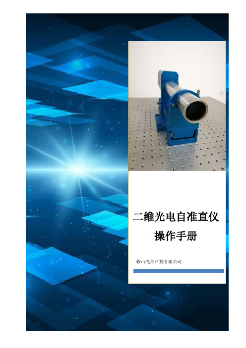
光准二维光电自准直仪操作手册说明书

二维光电自准直仪操作手册鞍山光准科技有限公司鞍山光准科技有限公司二维光电自准直仪操作手册目录1保修及有限责任 (1)维护 (1)功能和损坏的责任 (1)附件 (1)安全说明 (1)2设计用途 (2)3功能描述 (3)3.1二维光电自准直仪简介 (3)3.1.1自准直原理 (3)3.1.2主要技术指标 (4)3.1.3自准直仪主要功能 (5)3.1.4自准直仪主要特点 (5)3.2部件描述 (6)3.2.1自准直测头 (6)3.2.2网络连接线和电源箱 (6)3.2.3电脑 (7)3.2.4二维摆角调整底座 (7)3.2.5反射镜 (7)3.2.6激光找像器 (7)4软件介绍 (8)4.1整体界面 (8)4.1.1控制区 (8)4.1.2 显示区 (9)4.2菜单栏 (10)5操作 (13)5.1单位 (13)5.2标定 (13)5.3绝对测量与相对测量 (14)5.4有效位数设置 (14)5.5实时采集和单帧采集 (15)5.6自动测量和手动测量 (16)5.7动态测量和单次测量 (16)5.8数据的保存和查看 (17)5.9量程扩展 (17)5.10刻度显示 (18)5.11公差显示 (18)6测量 (20)6.1直线度测量 (20)6.1.1准备 (20)6.1.2输入 (20)6.1.3采样 (21)6.1.4查看结果 (22)6.1.5生成word (24)6.2平面度测量 (25)6.2.1网格布点法平面度测量 (25)6.2.2对角线布点法平面度测量 (30)6.3平行度测量介绍 (34)6.4垂直度测量介绍 (34)7附录: (35)1保修及有限责任维护该光电自准直仪在更改或维护时只能使用鞍山光准科技有限公司提供的原装部件,并且只能由鞍山光准科技有限公司明确授权的人员进行。
功能和损坏的责任该光电自准直仪如因维护不当或者由非鞍山光准科技有限公司明确授权的人员进行更改导致的仪器不能正常运行,或得不到精确结果,鞍山光准科技有限公司不承担任何责任。
- 1、下载文档前请自行甄别文档内容的完整性,平台不提供额外的编辑、内容补充、找答案等附加服务。
- 2、"仅部分预览"的文档,不可在线预览部分如存在完整性等问题,可反馈申请退款(可完整预览的文档不适用该条件!)。
- 3、如文档侵犯您的权益,请联系客服反馈,我们会尽快为您处理(人工客服工作时间:9:00-18:30)。
系统灵敏度调整................................................4-19 处理软件详述....................................................4-20
5
测量技巧 ............................................................... 5-1
4
操作指南 ............................................................... 4-1
4.1 4.1.1 4.1.2 4.1.3 测量准备..............................................................4-1 安放自准直仪 ..............................................4-1 连接电源及数据线缆 ..................................4-1 驱动安装......................................................4-1 III
6
技术数据 ............................................................... 6-1
6.1 自准直仪主机......................................................6-1 6.1.1 6.1.2 6.1.3 6.2 6.3 6.4 AUTOMAT ULTRA-3045 主机 ..................6-1 AUTOMAT ULTRA-2040 主机 ..................6-2 AUTOMAT ULTRA-2045 主机 ..................6-3 电源供应..............................................................6-4 反光镜..................................................................6-4 选配附件..............................................................6-4
公司主页:
II
AUTOMAT ULTRA 系列双轴光电自准直仪
目录
目录 1 产品概述 ............................................................... 1-1
1.1 1.2 1.3 设计用途..............................................................1-1 工作环境..............................................................1-2 使用注意事项......................................................1-2
2
功能描述 ............................................................... 2-1
2.1 2.2 2.3 仪器组成..............................................................2-1 测量原理..............................................................2-2 产品特性..............................................................2-3
©2007-2014 天津市奥特梅尔光电科技有限公司 - 版权所有 本产品由天津市奥特梅尔光电科技有限公司设计生产
I
重要说明
AUTOMAT Ultra 系列双轴光电自准直仪
获取进一步信息,请联系: 天津市奥特梅尔光电科技有限公司 地址: 邮编: 电话: 传真: 电子邮件: 产品销售:sales@ 技术支持:support@ 中国天津市华苑产业园区兰苑路 9 号 1-404 室 300384 +86-022-83719418 +86-022-83719418
7 8 9
维护和小心 ........................................................... 7-1 保修 ...................................................................... 8-1 自准直仪选配件 ................................................... 9-1
AUTOMAT ULTRA 系列双轴光电自准直仪
目录
5.5 5.6
注意事项..............................................................5-3 测量过程实例......................................................5-4
目录
AUTOMAT ULTRA 系列双轴光电自准直仪
9.7 9.8
多轴倾斜平台(DM90) ...................................9-6 专用检测桥板(QBY200) ...............................9-7
用户手册(简体中文版本)
©2007-2014 版权所有 All Rights Reserved REV.D
AUTOMAT ULTRA 系列双轴光电自准直仪
重要说明
重要说明
为了使您更好地了解仪器性能,正确、安全地使用本系 列光电自准直仪,请您在使用前仔细阅读本手册,并妥善保 存备用。为便于阅读,本手册中的部分插图和显示内容作了 简化处理。 由于本产品的不断更新和改进,本手册内容可能与用户 最终产品规格和参数存在差异,最终产品规格和参数以用户 购买产品包装内的手册或规格书为准。 本公司尽力保证本手册中全部内容的正确性与可靠性, 但是疏漏之处在所难免,公司将不为此承担任何法律责任。 本手册内容只限于此类产品的最终用户自行使用,本公司未 授权任何单位和个人在未征得本公司书面同意下散发、传播 和引用本手册任何内容,为此造成的一切法律责任本公司将 追究到底。
4.2.1 4.2.2 4.2.3 4.2.4 4.2.5 4.2.6 4.2.7 4.2.8 4.2.9 4.2.10 4.2.11 4.2.12 4.3 4.4
启动和关闭测量软件 ..................................4-6 操作界面......................................................4-7 启动/停止测量.............................................4-8 模式..............................................................4-8 单位..............................................................4-8 放大缩小......................................................4-9 公差带........................................................4-10 坐标系........................................................4-11 声音提示....................................................4-11 保存测量值................................................4-12 参数设定....................................................4-14 联系信息....................................................4-19
5.1 5.2 5.3 5.4 IV 使用环境..............................................................5-1 反射镜..................................................................5-1 找像......................................................................5-2 调平......................................................................5-3
