SD卡接口规范的完整翻译
SD卡功能描述(翻译)
4 SD卡功能描述4.1 概述主机与卡之间的所有通讯都由主机控制。
主机发送两类命令:广播命令和定址命令(点对点)。
●广播命令:广播命令适用于所有卡,部分命令需要响应回复。
●定址命令(点对点)定址命令发给已确定地址的卡,引发卡响应回复。
表格4-1显示卡片辨识模式命令流程总览,表格4-3针对数据传输模式。
表格4-19和表格4-28罗列了所有命令。
表4-29罗列了当前状态、命令接收和随后模式之间的依赖关系。
在接下去的章节中,会首先描述各类卡片操作模式。
然后,定义始终信号控制条件。
SD卡所有关于命令、响应、状态转换、错误条件和定时都会在随后的章节中描述。
SD卡系统(主机和卡片)定义两种操作模式:●卡片辨识模式主机复位后或者在总线上搜索新卡时,会进入卡片辨识模式。
卡片复位后也进入这个模式,直到收到SEND_SCR命令(CMD3)。
●数据传输模式当卡片的RCA首次确定后立即进入数据传输模式。
主机要识别完总线上所有卡片后进入数据传输模式。
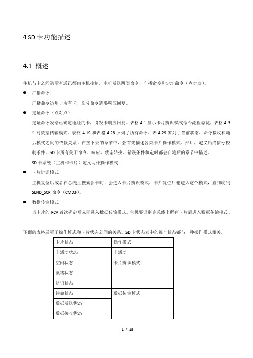
下面的表格展示了操作模式和卡片状态之间的关系。
SD卡状态表中的每个状态都与一种操作模式相关。
表4-1 卡片状态和操作模式总览4.2 卡片辨识模式在卡片辨识期间,主机复位所有在卡片辨识模式中的SD卡,确认操作电压范围,辨识卡片以及要求确定相对卡片地址(RCA)。
这个操作通过SD卡CMD口线各自独立完成。
卡片辨识模式中所有的数据传输只能使用CMD口线通道(CMD)。
在卡片辨识过程中,SD卡使用辨识时钟速率f OD(见6.7章)作为SD卡时钟频率。
4.2.1 卡片复位命令GO_IDLE_STATE(CMD0)是一个软复位命令,要求卡片立即忽略当前模式进入空闲模式。
卡片在非活动模式时该命令无效。
主机上电后,所有卡片进入空闲模式,包括之前在非活动模式下的卡片。
在上电或CMD0命令后,所有卡片CMD口线进入输入模式,等待下个命令的起始位。
卡片初始化时使用默认相对地址(RCA=0x0000),以及默认驱动寄存器设置(最低速度,最大驱动电流能力)。
SD2.0协议标准完整版[1-6章中文翻译]介绍
![SD2.0协议标准完整版[1-6章中文翻译]介绍](https://img.taocdn.com/s3/m/807ed26ffe4733687e21aa84.png)
【翻译:沙贝@中科创达 2014.安全、容量、性能、和环境需求的新型音视频电子存储卡。 Sd 卡包含一个内容保护机制,符合 SDMI 标准,并且有更快的速度和更高的容量。 Sd 卡的安全系统采用双向认证和“新密码算法”来防止卡的内容被非法使用。也可以 对用户自己的数据进行非安全访问。 SD 卡也支持基于常用标准的第二安全系统, 比如 ISO-7816, 这样就可以用于将 SD 卡连 接到共用网络和其他系统,来支持移动电子商务和数字签名的应用。 除了 SD 卡外,还有 SDIO 卡。SDIO 卡规范在一个单独的规范中定义,命名为“SDIO 卡 规范” ( 可以从 SD 协会得到) 。SDIO 规范定义了一个 SD 卡可能包含不同的 IO 单元同 SD host 之间的接口。SDIO 卡可以包含存储功能,以及 IO 功能。SDIO 卡的存储部分应该完全兼容 SD 卡规范。SDIO 卡基于并兼容 SD 卡。这种兼容包括机械、电气、电源、信号和软件。Sdio 卡的意图是为移动电子设备在低功耗情况下提供高速数据读写。一个主要目标是一个 IO 卡 插到非 SDIO 主机中,不会引起物理损坏或者设备和软件的中断。 这种情况下 IO 卡应该被简 单的忽略掉。一旦插入一个 SDIO 主控,卡的检测将以常规的方法描述,即带有 SDIO 规范扩 展的 SD 卡规范 SD 卡通信是基于 9-pin 接口(时钟,命令,数据 x4,电源 x3),设计在最大 50M 频率以 及低电下工作。通信协议是本规范的一部分。SD 规范分为几个文件: SD 规范安全规格 SD specifications Security Spec 音频规范(Audio) 文件系统规范 Sd 规范物理层规范 Mc-EX 接口规范 SDIO 卡规范 其他应用文档
外文翻译《SD安全数码卡产品手册》

本科毕业设计(外文翻译)SanDisk Secure Digital Card Product ManualSD安全数码卡产品手册1. IntroduceThe Secure Digital is a flash-based memory card that is specifically designed to meet the security, capacity, performance and environment requirements inherent in newly emerging audio and video consumer electronic devices. The SD Card includes a copyright protection mechanism that complies with the security of the SDMI standard, and is faster and capable of higher Memory capacity. The SD Card security system uses mutual authentication and a “new cipher algorithm” to protect from illegal usage of the card content. A non-secured access to the user‘s own content is also available. The physical form factor, pin assignment and data transfer protocol are forward compatible with the SD Card, with some additions.The SD Card communication is based on an advanced nine-pin interface (Clock, Command, 4xData and 3xPower lines) designed to operate in a low voltage range. The communication protocol is defined as part of this specification. The SD Card host interface supports regular MultiMediaCard operation as well. In other words, MultiMedia Card forward compatibility was kept. Actually the main difference between SD Card and MultiMediaCard is the initialization process. The SD Card specifications were originally defined by MEI (Matsushita Electric Company), Toshiba Corporation and SanDisk Corporation. Currently, the specifications are controlled by the Secure Digital Association (SDA). The SanDisk SD Card was designed to be compatible with the SD Card Physical Specification.The SD Card interface allows for easy integration into any design, regardless of microprocessor used. For compatibility with existing controllers, the SanDisk SD Card offers, in addition to the SD Card interface, an alternate communication protocol, which is based on the SPI standard.The current SD Card provides up to 1024 million bytes of memory using flash memory chips, which were designed especially for use in mass storage applications. In addition to the mass storage specific flash memory chip, the SD Card includes an on-card intelligent controller which manages interface protocols, security algorithms for copyright protection, data storage and retrieval, as well as Error Correction Code (ECC) algorithms, defect handling and diagnostics, power management and clock control.1.1. ScopeThis document describes the key features and specifications of the SD Card, as well as the information required to interface this product to a host system.1.2. Product ModelsThe SD Card is available in the capacities shown in Table 1-1.SDSDB = Binary NAND technology.SDSDJ = Multi Level Cell (MLC) NAND technology.SDSDH = Ultra SD CardInterface Figure 1-1. SD Card Block Diagram1.3 System FeaturesThe SD Card provides the following features:●U p to 2-GB of data storage.●S D Card protocol compatible.●S upports SPI Mode.●T argeted for portable and stationary applications for secured (copyrights protected)and non-secured data storage.●V oltage range:●O ther commands and memory access: 2.7-3.6V.●V ariable clock rate 0-25 MHZ.●U p to 25 MB/sec data transfer rate (using 4 parallel data lines).●P assword Protected of Cards (not on all models).●W rite Protect feature using mechanical switch.●B uilt-in write protection features (permanent and temporary).●C ard Detection (Insertion/Removal).●A pplication-specific commands.●C omfortable erase mechanism.The performance of the communication channel is described inTable 1-2.1.4. SD Card StandardSanDisk SD Cards are fully compatible with the following SD Card Physical Layer Specification standard:The SD Card Physical Layer System Specification, Version 1.101.5 Functional DescriptionSanDisk SD Cards contain a high level, intelligent subsystem as shown in Figure 1-1. This intelligent (microprocessor) subsystem provides many capabilities not found in other types of memory cards. These capabilities include:●Host independence from details of erasing and programming flash memory.●Sophisticated system for managing defects (analogous to systems found in magneticdisk drives).●Sophisticated system for error recovery including a powerful error correction code(ECC).1.5.1. Flash Technology IndependenceThe 512-byte sector size of the SD Card is the same as that in an IDE magnetic disk drive. To write or read a sector (or multiple sectors), the host computer software simply issues a Read or Write command to the SD Card. This command contains the address. The host software then waits for the command to complete. The host software does not get involved in the details of how the flash memory is erased, programmed or read. This is extremely important as flash devices are expected to get more and more complex in the future. Because the SD Card uses an intelligent on-board controller, the host system software will not require changing as new flash memory evolves. In other words, systems that support the SD Card today will be able to access future SanDisk SD Cards built with new flash technology without having to update or change host software.1.5.2. Defect and Error ManagementSD Cards contain a sophisticated defect and error management system. This system is analogous to the systems found in magnetic disk drives and in many cases offers enhancements. For instance, disk drives do not typically perform a read after write to confirm the data is written correctly because of the performance penalty that would be incurred. SD Cards do a read after write under margin conditions to verify that the data is written correctly. In the rare case that a bit is found to be defective, SD Cards replace this bad bit with a spare bit within the sector header. If necessary, SD Cards will even replace the entire sector with a spare sector. This is completely transparent to the host and does not consume any user data space.The SD Card’s soft error rate specification is much better than the magnetic disk drivespecification. In the extremely rare case a read error does occur, SD Cards have innovative algorithms to recover the data. This is similar to using retries on a disk drive but is much more sophisticated. The last line of defense is to employ a powerful ECC to correct the data. If ECC is used to recover data, defective bits are replaced with spare bits to ensure they do not cause any future problems. These defect and error management systems coupled with the solid-state construction give SD Cards unparalleled reliability.1.5.3. Copyright ProtectionA detailed description of the Copyright Protection mechanism and related security SD Card commands can be found in the SD Card Security Specification document from the SD Card Association. All SD Card security related commands operate in the data transfer mode.As defined in the SDMI specification, the data content that is saved in the card is saved already encrypted and it passes transparently to and from the card. No operation is done on the data and there is no restriction to read the data at any time. Associated with every data packet (song, for example) that is saved in the unprotected memory there is a special data that is saved in a protected memory area. For any access (any Read, Write or Erase command) from/to the data in the protected area. For an authentication procedure is done between the card and the connected device, either the LCM (PC for example) or the PD (portable device, such as SD player). After the authentication process passes, the card is ready to accept or give data from/to the connected device. While the card is in the secured mode of operation (after the authentication succeeded) the argument and the associated data that is sent to the card or read from the card are encrypted. At the end of the Read, Write or Erase operation, the card gets out automatically of its secured mode.1.5.4. EnduranceSanDisk SD Cards have an endurance specification for each sector of 100,000 writes typical (reading a logical sector is unlimited). This far exceeds what is typically required in nearly all applications of SD Cards. For example, even very heavy use of the SD Card in digital still cameras, cellular phones, personal communicators, pagers and voice recorders will use only a fraction of the total endurance over the typical device’s lifetime. For instance, it would take over 10 years to wear out an area on the SD Card on which a file of any size (from 512 bytes to maximum capacity) was rewritten 3 times per hour, 8 hours a day, 365 days per year. With typical applications, the endurance limit is not of anypractical concern to the vast majority of users.1.5.5. Wear LevelingWear-leveling is an intrinsic part of the Erase Pooling functionality of SD using NAND memory. The SD Card’s Wear Level command is supported as a NOP operation to maintain backward compatibility with existing software utilities.1.5.6. Using the Erase CommandThe Erase (sector or group) command provides the capability to substantially increase the write performance of the SD Card. Once a sector has been erased using the Erase command, a write to that sector will be much faster. This is because a normal write operation includes a separate sector erase prior to write.1.5.7. Automatic Sleep ModeA unique feature of the SanDisk SD Card (and other SanDisk products) is automatic entrance and exit from sleep mode. Upon completion of an operation, the SD Card will enter the sleep mode to conserve power if no further commands are received within 5msec. The host does not have to take any action for this to occur. In most systems, the SD Card is in sleep mode except when the host is accessing it, thus conserving power. When the host is ready to access the SD Card and it is in sleep mode, any command issued to the SD Card will cause it to exit sleep and respond.1.5.8. Hot InsertionSupport for hot insertion will be required on the host but will be supported through the connector. Connector manufacturers will provide connectors that have power pins long enough to be powered before contact is made with the other pins. Please see connector data sheets for more details. This approach is similar to that used in PCMCIA and MMCA devices to allow for hot insertion.1.5.9. SD Card—SD Bus ModeThe following sections provide valuable information on the SC Card in SD Bus mode.1.5.9.1. SD Card Standard ComplianceThe SD Card is fully compliant with SD Card Physical Layer Standard Specification V1.01. The structure of the Card Specific Data (CSD) register is compliant with CSD Structure 1.0.1.5.9.2. Negotiating Operation ConditionsThe SD Card supports the operation condition verification sequence defined in the SD Card standard specifications. Should the SD Card host define an operating voltage range, which is not supported by the SD Card it will put itself in an inactive state and ignore any bus communication? The only way to get the card out of the inactive state is by powering it down and up again. In Addition the host can explicitly send the card to the inactive state by using the GO_INACTIVE_STATE1.SD卡介绍SD卡(安全数码卡)是以FLASH技术为依托的记忆卡,特为满足新兴的视频和音频电器的安全,容量,运行和环境要求而设计。
(完整版)SD卡协议-中文

(完整版)SD卡协议-中文一概述1. SD总线模式下CLK:时钟信号CMD:双向命令和响应信号DAT0-3:双向数据信号VDD,VSS:电源和地信号SD模式下允许有一个主机, 多个从机(即多个卡), 主机可以给从机分别地址. 主机发命令有些命令是发送给指定的从机,有些命令可以以广播形式发送.SD模式下可以选择总线宽度, 即选用几根DAT信号线, 可以在主机初始化后设置.2. SD总线协议SD模式下的命令和数据流都有一个开始位和结束位.>命令: 是在CMD上传输的用于启动一个操作的比特流. 由主机发往从机, 可以是点对点也可以是广播的.>响应: 是在CMD上传输的用于之前命令回答的比特流. 由从机发往主机.>数据: 是在DAT上传输的比特流, 双向传输.无响应模式无数据模式多块读操作模式多块写操作模式命令格式响应格式数据格式SD卡上电后会自动初始化,通过给卡发送CMD0也可以复位卡.二.SD卡命令描述.1.广播命令:给所有卡都发送, 某些命令需要响应.2.点对点命令给指定地址的卡发送, 需要响应.SD卡系统有两种工作模式:1.卡识别模式.主机上电复位后即处于此模式,它会在总线上等待卡. 卡复位后也处于此模式, 直到SEND_RCA(CMD3)命令到来.2.数据传输模式.卡收到SEND_RCA(CMD3)命令后即进入此模式. 主机识别到卡后也进入此模式.卡状态和工作模式对照表1.卡识别模式.此模式下主机复位总线所有的卡, 验证工作电压, 询问卡的地址. 这个模式下所有数据的传输都是只通过CMD线来完成.1)卡的复位.当卡上电或收到GO_IDLE_STATE (CMD0)命令后, 卡即进入Idle State状态. 此时卡将其RCA设为0, 相关寄存器设为传输稳定的最优模式.2)工作电压验证每个卡的最高和最低工作电压存储在OCR. 只有当电压比配时, CID和CSD的数据才能正常传输给主机.SD_SEND_OP_COND (ACMD41)命令用来判断卡的工作电压是否符合, 如果不符合的话, 卡应该放弃总线操作, 进入Inactive State状态. 在发送SD_SEND_OP_COND (ACMD41)命令前记得要首先发送APP_CMD (CMD55).卡的状态变换图.ACMD41命令响应中的BUSY位也用于卡表示其还没准备好, 主机此时应重发ACMD41命令,直到卡准备好.主机在这个阶段的ACMD41中不允许改变工作电压, 如果确实想改变的话, 应该先发送CMD0, 然后再发送改变后的ACMD41.GO_INACTIVE_STATE (CMD15)命令用于使指定地址的卡进入Inactive State模式.3)卡识别过程.ALL_SEND_CID (CMD2)命令用于获取卡的CID信息, 如果卡处于Ready State, 它就会在CMD线上传送它的CID信息, 然后进入Identification State模式. 紧接着发送CMD3 (SEND_RELATIVE_ADDR)命令, 用于设置卡新的地址. 卡收到新的地址后进入Stand-by State 模式.2.数据传输模式.数据传输模式下卡的状态转变图进入数据传输模式后, 主机先不停的发送SEND_CSD (CMD9)命令获取卡的CSD信息. SET_DSR (CMD4)用于设置卡的DSR寄存器, 包括数据总线宽度, 总线上卡的数目, 总线频率, 当设置成功后, 卡的工作频率也随之改变. 此步操作是可选的.CMD7命令用于使指定地址的卡进入传输模式, 任何指定时刻只能有一个卡处于传输模式.传输模式下所有的数据传输都是点对点的, 并且所有有地址的命令都需要有响应..所有读命令都可以由CMD12命令停止,之后卡进入Transfer State. 读命令包括单块读(CMD17), 多块读(CMD18), 发送写保护(CMD30), 发送scr(ACMD51)和读模式一般命令(CMD56)..所有写命令都可以由CMD12命令停止. 写命令包括单块读(CMD24), 多块读(CMD25), 写CID(CMD26), 写CSD(CMD27),锁和解锁命令(CMD42)和写模式一般命令(CMD56)..当写命令传输完成后, 卡进入Programming State(传输成功)或Transfer State(传输失败).如果一个卡写操作被停止,但其前面数据的CRC和块长度正确, 数据还是会被写入..卡要提供写缓冲, 如果写缓冲已满并且卡处于Programming State, DAT0保持低BUSY. .写CID,CSD, 写保护, 擦除命令没有缓冲, 当这些命令没完时, 不应发送其他的数据传输命令..参数设置命令在卡被编程时是不允许发送的, 这些命令包括设置块长度(CMD16), 擦除块起始(CMD32)和擦除块结束(CMD33)..当卡正编程时读命令是禁止的..用CMD7使另一个卡进入Transfer State不会终止当前卡的编程和擦除, 当前卡会进入Disconnect State并且释放DAT线.. Disconnect State模式的卡可通过CMD7重新被选中,此时卡进入Programming State 并且使能busy信号.. CMD0或CMD15会终止卡的编程操作, 造成数据混乱, 此操作应禁止.1)总线宽度选择命令ACMD6命令用于选择总线宽度, 此命令只有在Transfer State有效. 应在CMD7命令后使用.2)块读命令块是数据传输的最小单位, 在CSD (READ_BL_LEN)中定义, SD卡为固定的512B.每个块传输的后面都跟着一个CRC校验. CMD17(READ_SINGLE_BLOCK)用于传输单个块,传输完之后,卡进入Transfer State. CMD18 (READ_MULTIPLE_BLOCK)用于多个块的传输,直到收到一个CMD12命令.3)块写命令与块读命令类似, 每个块传输的后面都跟着一个CRC校验.卡写数据时会进行CRC校验.多块写比重复的单块写更能提高效率.如果CSD中的WRITE_BLK_MISALIGN没设置, 并且发送的数据不是块对齐的, 卡会设置状态寄存器中的ADDRESS_ERROR位,并且进入Receive-data-State状态等待停止命令.此时写操作也会停止, 并且卡会设置其的WP_VIOLATION位.如果写缓冲满的话, 卡会停止接受WRITE_BLOCK命令. 此时主机应发送SEND_STATUS (CMD13)命令, 卡返回数据的READY_FOR_DATA位标志卡是否准备好接受新的数据.在多块写操作中通过事先发送ACMD23命令可提高写速度. ACMD23用于定义接下来要写数据的块的数目. 每次多块写操作后, 这个值又被设为默认的1.ACMD22会使卡返回写成功的块数目.4)擦除命令擦除命令的顺序是: ERASE_WR_BLK_START(CMD32),ERASE_WR_BLK_END(CMD33)an d ERASE (CMD38).如果(CMD38或(CMD32, 33)接收到出错信息, 卡会设置状态寄存器中的ERASE_SEQ_ERROR 位并且重新等待新的命令时序.如果接收到时序错误命令, 卡会设置其ERASE_RESET位并且重新等待新的命令时序.5)写保护管理三种机制:-.写保护物理开关-.卡内部写保护通过设置CSD中的WP_GRP_ENABLE位和WP_GRP_SIZE位, SET_WRITE_PROT和CLR_WRITE_PROT命令用来设置和清除保护机制.-. 密码保护.三. 时钟控制如果主机要发送1K的数据, 但是主机缓冲区只有512B, 那么主机可以在发送完前512B 后, 可以先停止时钟, 然后把后512B填充入缓冲区, 再启动时钟, 这样卡并不会检测要两次发送之间的间隔, 认为其是一次完整的数据发送过程.四 CRC校验1.CRC7CRC7用于所有的命令, 除R3以外的响应, 以及CID和CSD寄存器.2.CRC16CRC16用于数据块的校验五. 错误类型.1. CRC错误和命令非法错误命令的CRC校验出错, 卡设置其状态寄存器的COM_CRC_ERROR 位.非法命令错误, 卡设置其状态寄存器的ILLEGAL_COMMAND位.非法命令包括:不支持的命令,未定义的命令以及当前状态不支持的命令.2. 读,写和擦除超时.卡应该在指定的时间内完成一个命令或返回移动的错误信息. 如果在指定的超时时间内主机收不到响应, 应认为卡停止工作, 应重新复位卡.六命令1. 命令类型:- bc不需要响应的广播命令.- bcr需要响应的广播命令. 每个卡都会独立的接收命令和发送响应.- ac点对点命令, DAT线上没数据- adtc点对点命令, DAT线上有数据所有命令均遵守上图中的格式, 总共48位. 首先是1个起始位0,接着是1个方向位(主机发送位1), 6个命令位( 0-63 ), 32位参数(有些命令需要), CRC7位校验, 1个停止位.2.卡命令根据不同的类型分成了不同的Class, 见下表,其中Class0,2,4,5,8是每个卡都必须支持的命令, 不同的卡所支持的命令保存在CSD中.3.命令详细描述1)基本命令Class02)读命令Class23)写命令Class43)擦除命令Class54)应用特定命令Class8下表中的所有命令使用前都应先跟一个APP_CMD(CMD55)命令七. 卡状态转换表八. 应答.所有的应答都是通过CMD发送,不同的应答长度可能不同.总共有四种类型的应答.1. R1: 长度位48位.注意每个块传输完成后有一个BUSY位.2.R1b:与R1类似, 只是将BUSY位加入响应中.3.R2(CID CSD寄存器) : 长度为136位, CID为CMD2和CMD10的应答, CSD为CMD9的应答.4.R3(OCR寄存器):长度位48位. 作为ACMD41的应答.5.R6(RCA地址应答):长度为48位九. 卡的状态SD卡支持两种状态:-卡状态:与MMC卡兼容.-SD卡状态:扩充到了512位.1.卡状态:R1应答包含一个32位的卡状态.见下表.其中Type中的含义为:E:错误位. S:状态位. R:根据命令在响应中设置.X:根据在命令执行期间设置, 必须再次读此位才能获得命令执行后的情况.Clear Condition:A: 与卡的当前状态有关B: 总是与命令有关,无效的命令会清除此位.C: 通过读此位来清除下表指明了哪些命令可能使哪些位产生变化2.SD卡状态:这些位通过DAT线传输, 并伴有CRC16校验. 其是作为ACMD13的应答.十. 卡存储器形式.-块:块是基本读写命令的单位,它可以是固定的或可变的. 关于块的大小以及其是否可变性存储在CSD中.-扇区:扇区是擦除命令的单位, 它是固定的值,保存在CSD中.十一. 时序图时序图中字母含义:1.命令和应答1)卡识别和卡工作电压确认模式:CMD2,ACMD412)地址分配模式:CMD33)数据传输模式:4)命令结束->下一个命令:5)两个命令直接1)单块读:CMD172)多块读:读过程时序.停止命令时序3.数据写1)单块写:注意Busy信号.2)多块写:多块写命令时序停止命令时序卡主动停止时的时序。
SD卡插槽套接字说明书

S
Supply voltage ground
P④
VDD
S
Supply voltage
P⑤
CLK
l
Clock
P⑥
Vss2
S
Supply voltage ground
P⑦
DAT 0
l/0/PP
Date Line [Bit 0]
P⑧
DAT 1
l/0/PP
Date Line [Bit 1]
P⑨
DAT 2
l/0/PP
6,500 Cycles
5,500 Cycles
5,500 Cycles
4,000 Cycles
-35℃~+85℃(Operating Temp:
)
Page1 Unit:mm
SD CARD
E C B
D A
No.
NAME
①A
开口端子
②B
外壳
③ C 弹片端子 1
④ D 弹片端子 2
⑤E
塑胶底座
Material declaration MATERIAL
本品不屬於危害性廢棄物,須丟棄時可以委託 回收商予以回收再生處理。Products do not belong to hazardous waste,When waste can
recycling processing
注記 NOTICE
1.碩方公司擁有最終解釋權;The SOFNG company reserves the right of final interpretation; 2.文件禁止外洩、轉載;Leaked and reproduced prohibited; 3.未經授權修改無效。Modify is invalid.
sd卡、emmc卡、sdhc、sdio接口、nand等简略说明

简要总结2017-5-17xdk1.Sim卡和sd/sdio/sdhc什么的不一样,只有复位、电源、时钟、一根数据线。
看手机版设计,vcc电压是lte模组出来供电,且会1.8V 3.3V切换。
VPP悬空处理即可,不需要编程。
2.Nand接口和sdio/sdhc什么的也不是一种口。
Nand属于localbus总线,一般和nor共用(虽然和sdhc口一样有8位双向信号线)。
Nand主要就是we/oe/ce/ale/cle/8位命令地址数据线。
3.Sd(Secure Digital Card)卡最大支持2GB容量(据说由MMC演变未来),4bit数据线。
还有clk/cmd信号,cmd用来区分命令还是数据。
文件系统fat12/16.4.sdhc("Secure Digital High Capacity高容量sd存储卡),支持2GB~32GB容量范围;和sd相比,8bit数据位。
Sdhc可以向下兼容sd卡(sd2.0以后的版本,老的不兼容)。
文件系统fat32。
5.sdxc(SD eXtended Capacity),容量更大目前可达64GB,理论上2TB,传输速度更快(300MB/s),exFAT文件系统.支持UHS104(新的超高速sd接口规格)6.sdio就是支持sd卡的接口,同时还外延了,支持其他支持sdio接口的设备,如蓝牙、网卡、电视卡等(见下文网络copy,具体工作模式没看透,支持spi、data1作为中断?暂时不影响我画图)。
7.sdhc接口,可以接sdhc卡,emmc卡。
8.eMMC(Embedded Multi Media Card)是由MMC协会(MultiMediaCard Association,2008年已并入JEDEC)提出的内置存储标准,主要针对手机和平板等移动设备设立。
在最新的eMMC5.1标准中存取带宽已经提升到600MB/s9.UFS(Universal Flash Storage)的出现比eMMC要晚一些。
SD6.0规范(简化版)学习笔记

SD6.0规范(简化版)学习笔记目录1.概述 (1)2.系统特点SYSTEM FEATURE (1)3.SD存储卡系统概要 (2)3.1按照读写特性,可分为读写卡以及只读卡。
(2) 3.2按供电电压可分为两类 (2)3.3卡容量 (2)3.4速率等级 (2)3.5总线拓扑 (2)3.6总线协议 (2)3.6.1SD总线协议 (2)3.6.2SPI总线协议 (4)3.6.3UHS-2总线协议 (4)3.7SD存储卡的管脚和寄存器 (5)3.7.1SD 总线管脚安排 (5)3.7.2UHS-2总线管脚安排 (5)3.8ROM卡(即前面提到的只读卡) (5)3.9UHS-1卡 (5)3.9.1支持的速率 (5)3.9.2UHS-1卡的类别 (5)3.9.3UHS-1主设备类别 (5)3.9.4UHS-1总线速率模式选择流程 (5)3.9.5UHS-1系统框图 (6)3.9.6UHS-1卡总线速率模式总结 (6)3.10UHS-2卡 (6)3.10.1UHS-2卡工作模式 (6)3.10.2UHS-2卡类别 (6)3.10.3UHS-2主设备和卡配合 (7)3.10.4UHS-2接口选择时序 (7)3.10.5UHS-2卡总线速率模式总结 (8)3.11应用性能等级 APPLICATION PERFORMANCE CLASS (8)3.12C ACHE (9)3.13SELF MAINTENANCE (9)3.14COMMAND QUEUE (9)3.15LV接口 (9)3.16UHS-2更高的总线速率(UHS-3) (9)4.SD存储卡的功能描述 (9)4.1概要 (9)4.2卡识别模式 (10)4.3数据传输模式 (10)4.4时钟控制 (10)4.5CRC (10)4.6E RROR CONDITION 出现错误的情况 (10)4.7命令 (10)4.8卡状态转换表 (10)4.9响应 (10)4.10SD存储卡的三种状态信息 (10)4.11M EMORY ARRAY PARTITIONING (10)4.12时序 (10)4.13速率等级划分 (10)4.13.1SDSC和SDHC的速率等级 (11)4.13.2SDXC卡的速率等级 (13)4.13.3UHS-1和UHS-2的速率等级 (13)4.13.4Video速率等级 (14)4.14E RASE TIMEOUT CALCULATION (15)4.15S ET B LOCK C OUNT命令 (15)4.16应用性能说明 A PPLICATION P ERFORMANCE S PECIFICATION (15)4.16.1应用性能等级 (15)4.16.2应用等级测试条件 (15)4.16.3应用等级性能参数 (15)4.17C ACHE (16)4.18S ELF MAINTENANCE 自维护 (16)4.19C ONMAND QUEUE模式 (16)5.卡寄存器 (16)6.SD存储卡硬件接口 (16)6.1热插拔 (16)6.2卡检测 (16)6.3电源保护(热插拔) (16)6.4电源 (16)6.4.1SD总线接口的上电时序 (16)6.4.2UHS-2接口的上电时序 (18)6.5P ROGRAMMABLE CARD OUTPUT DRIVER(可选) (19)6.6B US OPERATING CONDITIONS FOR 3.3V SIGNALING (19)6.6.1Threshold level for high voltage range (19)6.6.2Peak voltage and leakage current (19)6.6.3Power consumption (19)6.6.4Bus signal line load (19)6.6.5Bus signal levels (19)6.6.6总线时序(默认速率模式) (19)6.6.7总线速率(高速模式) (20)6.7D RIVE STRENGTH AND BUS TIMING FOR 1.8V SIGNALING (21)6.8ESD要求 (21)7.SPI模式 (21)1. 概述除了SD存储卡之外还有SDIO卡,SDIO卡基于SD存储卡,也兼容SD存储卡接口。
存储卡标准.CF.SD.SDHC.MMC.TF卡引脚定义对应关系

3
VSS1
电源地1 电源地1
4 VSS1
3 VSS1
4
VDD
电源
电源
5
6
VDD1 VDD2 4
VDD
4 VDD VDD
电源
电源
5
CLK
时钟 时钟SCK
7 CLK 5 CLK 5 CLK SCLK
时钟 时钟sck
6
VSS2
电源地2 电源地2
8 VSS2
6 VSS2
6 VSS VSS
电源地 电源地
7
DAT0
数据线0 主入从出
9 DAT0
7 DAT 7 DAT0 DO
数据线0 主入从出
8 DAT1
10 DAT1
8 DAT1
X
数据线1 保留
TF卡, 又叫 microS D卡,8 pin,外 形以及 在SD和 SPI工作 模式下 引脚定
数据线2 数据线3 命令线 电ห้องสมุดไป่ตู้ 时钟 电源地 数据线0
保留 片选/从选SS 主出从入 电源 时钟sck 电源地 主入从出
数据线1
保留
三星 MMC Micro卡 (512MB) 基本特征 卡式类型 MMC Micro 闪存卡容 量 512MB 外形尺寸 14*12*1. 1 产品重量 1 电压(V) 2.7V3.6V 其他性能 读:10 MB/s; 写:7 MB/s
SD
概念 SD卡, 数字安 全记忆 卡 (Secur
e Digital
Memory Card) ,是用 于移动 设备的 标准记 忆卡。 SD卡数 据传送 和物理 规范由 MMC发 展而 来,大 小和 MMC差 不多。 长宽和 MMC一 样,比 MMC稍 微外厚形了及 接口定 义SD卡为