FlexRay通信系统协议规范V2.1修订本A-勘误表V1
FlexRay通信协议中文版
一、FlexRay介绍FlexRay通讯协议运用于可靠的车内网络中,是一种具备故障容错的高速汽车总线系统。
它已经成为同类产品的基准,将在未来很多年内,引导汽车电子产品控制结构的发展方向。
FlexRay协议标准中定义了同步和异步帧传输,同步传输中保证帧的延迟和抖动,异步传输中有优先次序,还有多时钟同步,错误检测与避免,编码解码,物理层的总线监控设备等。
1.1汽车网络通信协议综述汽车网络通信协议在保证整个系统正常运行方面起着非常重要的作用。
它可以帮助解决系统很多问题,如数据共享、可扩展性、诊断接口等。
目前,应用于汽车领域的网络标准除了FlexRay还有很多,如CAN、LIN、J1850及MOST等。
CAN总线全称为“控制器局域网总线(Controller Area Network)”,是德国博世公司从80年代初为解决现代汽车中众多的控制与测试仪器之间的数据交换而开发的一种串行数据通信协议。
它是一种多主总线,通信介质可以是双绞线、同轴电缆或光导纤维。
CAN通信速率可达1Mbit/s,每帧的数据字节数为8个。
LIN(Local Interconnect Network,控制器局域网)总线是由LIN 协会发布的一种新型低成本串行通信总线,也称为经济型CAN网络。
LIN的目标是为现有汽车网络(例如CAN 总线)提供辅助功能,因此LIN总线是一种辅助的总线网络,在不需要CAN 总线的带宽和多功能的场合比如智能传感器和制动装置之间的通信使用LIN总线可大大节省成本。
J1850总线是1994年由汽车工程师协会颁布的标准,之后普及运用于美国车厂的汽车中。
不过,虽然美国各厂多采用J1850标准,但是各厂的实际做法又不相同,因此相对其他标准来说比较混乱。
由于J1850总线通信速率低,只适合用于车身控制系统及诊断系统,目前在美国逐步被CAN 所取代。
MOST(Media Oriented System Transport,面向媒体的系统传输)总线是采用光纤并用于智能交通及多媒体的网络协议,能够支持24.8Mbps的数据速率,与以前的铜缆相比具有减轻重量和减小电磁干扰的优势。
FlexRay总线网络管理策略

FlexRay总线网络管理策略车载网络管理的重要作用是协调网络中的节点同步进入睡眠状态。
此外,车载网络管理还应具备网络监测和诊断、网络配置管理的作用。
FlexRay总线协议是FlexRay联盟(FlexRay Consortium)制定的适用于汽车高速网络的新一代车载总线,具备高传输速率、硬实时、安全性和灵活性的特点。
FlexRay联盟目前只规定了物理层协议和数据链路层协议,没有制定网络管理方面的标准。
FlexRay总线协议特性分析(1)通信机制确定性FlexRay总线采用周期通信的方式,一个通信周期(Communication Cycle)可以划分为静态部分、动态部分、特征窗(SW, Symbol Window)和网络空闲时间(NIT, Network Idle Time)4个部分(图1)。
静态部分和动态部分用来传输总线数据,即FlexRay报文。
特征窗用来发送唤醒特征符(WUS, Wake Up Symbol)和媒介访问检测特征符(MTS, Media Access Test Symbol)。
网络空闲时间用来实现分布式的时钟同步和节点参数的初始化。
FlexRay总线所有节点的通信周期必须保持同步。
图1:FlexRay通信周期示例。
FlexRay节点如果通过发送网络管理协议数据单元(NMPDU,Network Management Protocol Data Unit)进行网络管理,NMPDU可以在静态部分或动态部分周期性传输。
而NMPDU 发送的允许或禁止由节点网络管理状态决定,因此所有FlexRay节点的网络管理状态转换必须在通信周期的间隔处执行。
然而,FlexRay总线的通信周期为全局时间,在总线运行过程中会根据部分节点的时间进行实时调整,所以网络管理状态转换不能以内部定时器的方式实现,必须使用计数器的方式配合总线通信周期实现,才能满足所有节点同步转换的要求。
(2)通信调度灵活性FlexRay总线在一个通信周期采用了两种接入时序:静态部分采用时分多址(TDMA, Time Division Multiple Access)的接入时序,动态部分采用柔性时分多址(FTDMA, Flexible TDMA)的接入时序。
汽车控制系统效能升级!FlexRay网络标准详解
汽车控制系统效能升级!FlexRay网络标准详解自2003年组建以来,AUTOSAR(汽车开放系统架构)联盟一直致力于改变车载网络和电子控制单元(ECU)的设计方式。
AUTOSAR提出了一个符合业界标准的车载网络设计方法,使行业能够集成、交换和传输汽车网络内的功能、数据和信息。
这一标准极大地促进了汽车原始设备制造商(OEM)及其一级供应商之间的合作,使他们能够以一种一致、明确且机器可读的格式来交换设计信息。
一辆汽车的不同部分对安全及性能有不同要求,而支持它们的车载网络必须具备可预测的安全性能。
随着汽车技术的不断演变,人们已经可以用一系列总线技术来连接豪华汽车上最多100个不同的ECU,这些总线技术通常包括LIN、CAN、FlexRay、MOST和基于以太网的架构。
如果靠手动来管理这些ECU 之间数以千计的信息和交互操作是不可能的,因此汽车设计人员必然用自动化设计和合成工具来预测网络性能和调整车载功能。
汽车数据总线一辆典型的现代化汽车将同时装配各类总线和协议并从LIN、CAN、FlexRay、MOST和以太网中选择合适的网络。
多媒体/视听信号和汽车环绕摄像系统需要更高的数据速率,因此汽车制造商和OEM厂商在网络解决方案上选择用以太网代替MOST.但对于许多标准汽车功能而言,LIN和CAN提供的带宽与性能就足够了。
在汽车架构中,ECU组合在一起形成“集群”,这些集群通过通信“网关”相连。
集群通常会共享同一类型的总线,因此要达到高可靠性、高速率的标准,就要采用FlexRay 网络,但要求没那么高的门锁ECU可以由CAN或LIN来负责。
ECU网关往往要连接不同类型的信号,并执行不同总线架构之间的映射和转换功能。
汽车行业对不断提高安全性和ISO26262等标准的合规性提出强烈需求,进而提升了车载网络的性能,同时也降低了制造和元件成本。
不断进步的网络标准可以适应越来越高的数据传输速率,汽车电缆也达到了安全且低成本的目标。
FlexRay通信系统协议规范V2.1修订本A-第七章 唤醒和启动
Chapter 7Wakeup and StartupThis chapter describes the procession of a FlexRay cluster from sleep mode to full operation and the integration of newly configured nodes into a FlexRay cluster already in operation.First the cluster wakeup is described in detail. Some application notes regarding the interaction between communication controller and host are provided.Following the wakeup section, communication startup and reintegration is described. This section also describes the integration of nodes into a communication cluster.7.1Cluster wakeupThis section describes the procedure64 used by communication controllers to initiate the cluster wakeup.7.1.1PrinciplesThe minimum prerequisite for a cluster wakeup is that the receivers of all bus drivers be supplied with power.A bus driver has the ability to wake up the other components of its node when it receives a wakeup pattern on its channel. At least one node in the cluster needs an external wakeup source.The host completely controls the wakeup procedure65. The communication controller provides the host the ability to transmit a special wakeup pattern (see Chapter 3) on each of its available channels separately. The wakeup pattern must not be transmitted on both channels at the same time. This is done to prevent a faulty node from disturbing communication on both channels simultaneously with the transmission. The host must configure which channel the communication controller shall wake up. The communication controller ensures that ongoing communication on this channel is not disturbed.The wakeup pattern then causes any fault-free receiving node to wake up if it is still asleep. Generally, the bus driver of the receiving node recognizes the wakeup pattern and triggers the node wakeup. The commu-nication controller needs to recognize the wakeup pattern only during the wakeup (for collision resolution) and startup phases.The communication controller cannot verify whether all nodes connected to the configured channel are awake after the transmission of the wakeup pattern66 since these nodes cannot give feedback until the startup phase. The host shall be aware of possible failures of the wakeup and act accordingly.The wakeup procedure supports the ability for single-channel devices in a dual-channel system to initiate cluster wakeup by transmitting the wakeup pattern on the single channel to which they are connected. Another node, which has access to both channels, then assumes the responsibility for waking up the other channel and transmits a wakeup pattern on it (see section 7.1.4.1).64 To simplify discussion, the sequence of tasks executed while triggering the cluster wakeup is referred to here as the wakeup"procedure" even though it is realized as an SDL macro, and not an SDL procedure. The normal grammatical use of the term is intended rather than the precise SDL definition. Since SDL processes are not used in the wakeup mechanism, the usage does not introduce ambiguity.65 The host may force a mode change from wakeup mode to the POC:ready state. Note, however, that a forced mode-changeto the POC:ready state during wakeup may have consequences regarding the consistency of the cluster.66 For example, the transmission unit of the bus driver may be faulty.The wakeup procedure tolerates any number of nodes simultaneously trying to wake up a channel and resolves this situation such that eventually only one node transmits the wakeup pattern. Additionally, the wakeup pattern is collision resilient; so even in the presence of a fault causing two nodes to simultaneously transmit a wakeup pattern the signal resulting from the collision can still wake up the other nodes.7.1.2DescriptionThe wakeup procedure is a subset of the Protocol Operation Control (POC) process. The relationship between the POC and the other protocol processes is depicted in Figure 7-167.Figure 7-1: Protocol operation control context.67 The dark lines represent data flows between mechanisms that are relevant to this chapter. The lighter gray lines are relevantto the protocol, but not to this chapter.7.1.3Wakeup support by the communication controllerThe host must initialize the wakeup of the FlexRay cluster. The host has to configure the wakeup channel pWakeupChannel while the communication controller is in the POC:config state.The host commands its communication controller to send a wakeup pattern on channel pWakeupChannel while the communication controller is in the POC:ready state. The communication controller then leaves the POC:ready state, begins the wakeup procedure (see Figure 7-2) and tries to transmit a wakeup pattern on the configured channel. Upon completion of the procedure it signals back the status of the wakeup attempt to the host (see section 9.3.1.3.1).The host must properly configure the communication controller before it may trigger the cluster wakeup. In the SDL description the wakeup procedure is realized as a macro that is called by the protocol operation control state machine (see Chapter 2).7.1.3.1Wakeup state diagramFigure 7-2: Structure of the wakeup state machine [POC].The parameter pWakeupChannel identifies the channel that the communication controller is configured to wake up. The host can only configure the wakeup channel in the POC:config state. After the communication controller has entered the POC:ready state the host can initiate wakeup on channel pWakeupChannel. Upon completing the wakeup procedure the communication controller shall return into the POC:ready state and signal to the host the result of the wakeup attempt.The return condition of the WAKEUP macro is formally defined as T_WakeupStatus in section 2.2.1.3 in Definition 2-5.The return status variable vPOC!WakeupStatus is set by the POC to•UNDEFINED, if the communication controller has not yet executed the WAKEUP mechanism since the last entry to the POC:default config state (see Figure 2-7), or when the POC responds to a CHI WAKEUP command,•RECEIVED_HEADER, if the communication controller has received a frame header without coding violation on either channel during the initial listen phase,•RECEIVED_WUP, if the communication controller has received a valid wakeup pattern on channel pWakeupChannel during the initial listen phase,•COLLISION_HEADER, if the communication controller has detected a collision during wakeup pattern transmission by receiving a valid header during the ensuing detection phase, •COLLISION_WUP, if the communication controller has detected a collision during wakeup pattern transmission by receiving a valid wakeup pattern during the ensuing detection phase,•COLLISION_UNKNOWN, if the communication controller has detected a collision but did not detecta subsequent reception event that would allow the collision to be categorized as either COLLI-SION_HEADER or COLLISION_WUP,•TRANSMITTED, if the wakeup pattern was completely transmitted.7.1.3.2The POC:wakeup listen stateFigure 7-3: Transitions from the POC:wakeup listen state [POC]68.The purpose of the POC:wakeup listen state is to inhibit the transmission of the wakeup pattern if existing communication or a startup is already in progress.68 For a single channel node, the unattached channel is assumed to always be idle.The timer tWakeup enables a fast cluster wakeup in a noise free environment, while the timer tWakeup-Noise enables wakeup under more difficult conditions when noise interference is present.When ongoing communication is detected or a wakeup of pWakeupChannel is already in progress, the wakeup attempt is aborted.7.1.3.3The POC:wakeup send stateFigure 7-4: Transitions from the state POC:wakeup send state [POC].In this state, the communication controller transmits the wakeup pattern on the configured channel and checks for collisions.Since the communication controller transmits the wakeup pattern on pWakeupChannel, it cannot really determine whether another node sends a wakeup pattern or frame on this channel during its transmission. Only during the idle portions of the wakeup pattern can it listen to the channel. If during one of these idle portions activity is detected, the communication controller leaves the send phase and enters a succeeding monitoring phase (POC:wakeup detect state) so that the cause of the collision might be identified and presented to the host.7.1.3.4The POC:wakeup detect stateFigure 7-5: Transitions from the state POC:wakeup detect state [POC].In this state, the communication controller attempts to discover the reason for the wakeup collision encoun-tered in the previous state (POC:wakeup send).This monitoring is bounded by the expiration of the timer tWakeup. The detection of either a wakeup pattern indicating a wakeup attempt by another node or the reception of a frame header indicating existing commu-nication causes a direct transition to the POC:ready state.7.1.4Wakeup application notesThe host must coordinate the bus driver and the communication controller wakeup modes. It must coordinate the wakeup of the two channels and must decide whether or not to wake a specific channel. Since proper behavior of the host is important to the wakeup procedure, the required host behavior is described here.7.1.4.1Wakeup initiation by the hostA host that wants to initiate a wakeup of the cluster should first check its bus driver(s) to see if they have received wakeup patterns. If the bus driver of a channel did not receive a wakeup pattern, and if there is no startup or communication in progress, the host shall try to wake this channel69.The host should not wake channels whose bus drivers have received a wakeup pattern unless additional information indicates that startup is not possible without an additional wakeup of those channels.70A single-channel node in a dual-channel cluster can trigger a cluster wake-up by waking its attached channel. This wakes up all nodes attached to this channel, including the coldstart nodes, which are always dual-channel. Any coldstart node that deems a system startup necessary will then wake the remaining channel before initiating communication startup.69 The host must distinguish between a local wakeup event and a remote wakeup received via the channel. This information isaccessible at the bus driver.70 This is done to speed up the wakeup process and to limit the amount of traffic on the channels, which reduces the number ofcollisions during this phase.7.1.4.1.1Single-channel nodesThis section describes the wakeup behavior of single-channel nodes in single- or dual-channel clusters. The bus driver is assumed to be in the BD_Sleep or BD_Standby mode. The host is assumed to have determined that a cluster wakeup should be triggered.1.The host first configures the communication controller. The coldstart inhibit mode71 shall be entered bysetting vColdStartInhibit to true.2.The host checks whether a wakeup pattern was received by the bus driver.3.The host puts the bus driver into the BD_Normal mode.4.If a wakeup pattern was received by the bus driver, the node should enter the startup (step 9) insteadof performing a wakeup.If no wakeup pattern received by the bus driver, the node may perform a wakeup of the attached chan-nel (which will eventually wake both channels of a dual-channel cluster).5.The host configures pWakeupChannel to the attached channel.6.The host commands the communication controller to begin the wakeup procedure.7.After its wakeup attempt is complete the communication controller returns the result of the wakeupattempt.8.The host commands the communication controller to leave the coldstart inhibit mode and to com-mence startup.7.1.4.1.2Dual-channel nodesThis section describes the wakeup behavior of dual-channel nodes in dual-channel clusters.Figure 7-6: A short example of how the wakeup of two channels can be accomplished in a fault-tolerant way by coldstart nodes.72A communication controller shall not send a wakeup pattern on both channels at the same time73. If it is necessary to wake both channels, the host can only wake them one at a time.71 This has no functional effect for non-coldstart nodes.72 Note that there is no requirement that a wakeup node be a coldstart node, or that a coldstart node be a wakeup node. In thisexample the wakeup nodes are also coldstart nodes, but this is not required.73 This requirement ensures that an erroneous communication controller cannot disturb all ongoing communication bytransmitting wakeup patterns on both channels at the same time.To avoid certain types of failures, a single communication controller should not wake up both channels. Instead, a different controller should wake up each channel.To accomplish this, a communication controller that has received a local wakeup event proceeds normally and only wakes a single channel, e.g., channel A (see Figure 7-6). Following this, it does not wake the other channel but rather enters startup. If it is a coldstart node, the coldstart inhibit flag must be set to true, so that it cannot actively initiate the cluster startup. Only after the node detects a wakeup pattern on channel B should it clear the coldstart inhibit flag and actively coldstart the cluster.Two example wakeup strategies are now given as examples to demonstrate how cluster wakeup can be accomplished. Neither strategy is concerned with the details of error recovery and therefore do not handle some error situations that are likely to occur.7.1.4.1.2.1Wakeup pattern reception by the bus driverThe bus drivers are assumed to be in the BD_Sleep or BD_Standby mode. The host is assumed to have determined that a cluster wakeup should be triggered.1.The host first configures the communication controller. It assumes both channels to be asleep. Thecoldstart inhibit mode74 shall be set.2.The host checks which of the bus drivers has received a wakeup pattern.3.The host puts all bus drivers that have received a wakeup pattern into BD_Normal mode (these chan-nels can be assumed to be awake).4.If both channels are awake, the host can proceed to startup (step 11).If both channels are asleep, the host shall wake up one of them.If one channel is asleep and one channel is awake, a non-coldstart host may wake up the channel that is asleep, but a coldstart host must wake up the channel that is asleep.5.The host configures pWakeupChannel to the channel to be awakened.6.The host activates the bus driver of pWakeupChannel.7.The host commands the communication controller to begin the wakeup procedure.8.The communication controller returns the result of the wakeup attempt.9.If the result of the wakeup attempt is TRANSMITTED, the host assumes pWakeupChannel to beawake and proceeds to startup (step 11).If the result of the wakeup attempt is RECEIVED_HEADER or COLLISION_HEADER, the host can assume that both channels are awake. It activates any remaining sleeping bus driver and proceeds to startup (step 11).If the result of the wakeup attempt is RECEIVED_WUP or COLLISION_WUP, the host assumes pWakeupChannel to be awake (return to step 4).If the result of the wakeup attempt is COLLISION_UNKOWN, an application-specific recovery strategy has to be employed, which is not covered by this document.10.The host commands the communication controller to begin the startup procedure.11.If all channels are awake, the host may command the communication controller to leave the coldstartinhibit mode. Otherwise, it waits until the bus driver of the still sleeping channel signals the reception ofa wakeup pattern. This bus driver shall then be put into the BD_Normal mode. As soon as all attachedchannels are awake, the host may command the communication controller to leave the coldstart inhibit mode.This method has the disadvantage that the channel pWakeupChannel cannot be listened to during the POC:wakeup listen state. If the bus driver of the channel is subject to an incoming link failure, ongoing communication might be disturbed and the node would not come up without additional error recovery strat-egies.74 This has no functional effect for non-coldstart nodes.7.1.4.1.2.2Wakeup pattern reception by the communication controllerThe wakeup pattern receiver of the communication controller is active as long as the CODEC is in WAKEUP mode. During this time the reception of a wakeup pattern will be directly signaled to the CHI and from there to the host.The bus drivers are assumed to be in the BD_Sleep or BD_Standby modes. The host is assumed to have determined that a cluster wakeup should be triggered.1.The host first configures the communication controller. It assumes both channels to be asleep. Thecoldstart inhibit mode75 shall be set.2.The host checks which of the bus drivers has received a wakeup pattern.3.The host puts both bus drivers into BD_Normal mode.4.If both channels are awake, the host can proceed to startup (step 10).If both channels are asleep, the host shall awake one of them.If one channel is asleep and one channel is awake, a non-coldstart host may wake up the channel that is asleep, but a coldstart host must wake up the channel that is asleep.5.The host configures pWakeupChannel to the channel that to be awakened.6.The host commands the communication controller to begin the wakeup procedure.7.The communication controller returns the result of the wakeup attempt.8.If the result of the wakeup attempt is TRANSMITTED, the host assumes pWakeupChannel to beawake and proceeds to startup (step 10).If the result of the wakeup attempt is RECEIVED_HEADER or COLLISION_HEADER, the hostassumes all attached channels to be awake and proceeds to startup (step 10).If the result of the wakeup attempt is RECEIVED_WUP or COLLISION_WUP, the host assumes pWakeupChannel to be awake (return to step 4).If the result of the wakeup attempt is COLLISION_UNKOWN, an application-specific recovery strategy has to be employed, which is not covered here.9.The host commands the communication controller to begin the startup procedure.10.If all channels are awake, the host may command the communication controller to leave the coldstartinhibit mode. Otherwise, it waits until the wakeup pattern receiver of the communication controller detects a wakeup pattern on the channel that is assumed to be asleep (this could already haveoccurred during one of the former steps). If the communication controller internal wakeup pattern detector receives a wakeup pattern on this channel, it is further assumed to be awake. As soon as all attached channels are awake, the host may command the communication controller to leave the cold-start inhibit mode.7.1.4.2Host reactions to status flags signaled by the communicationcontrollerThis section defines the status information that the communication controller can return to the host as result of its wakeup attempt and the recommended reaction of the host.7.1.4.2.1Frame header reception without coding violationWhen a frame header without coding violation is received by the communication controller on either available channel while in the POC:wakeup listen (or POC:wakeup detect) state the communication controller aborts the wakeup, even if channel pWakeupChannel is still silent.The host shall not command the communication controller to initiate additional wakeup attempts, since this could disturb ongoing communication. Instead, it shall command the communication controller to enter the startup to integrate into the apparently established cluster communication.75 This has no functional effect for non-coldstart nodes.7.1.4.2.2Wakeup pattern receptionThe communication controller has received a wakeup pattern on channel pWakeupChannel while in the POC:wakeup listen (or POC:wakeup detect) state. This indicates that another node is already waking up this channel. To prevent collisions of wakeup patterns on channel pWakeupChannel, the communication controller aborts the wakeup.If another channel is available that is not already awake, the host must determine whether the communi-cation controller is to wake up this channel. If all available channels are awake, the host shall command the communication controller to enter startup.7.1.4.2.3Wakeup pattern transmissionThe communication controller has transmitted the complete wakeup pattern on channel pWakeupChannel. The node can now proceed to startup. In a dual-channel cluster, coldstart nodes may need to be put into the coldstart inhibit mode (see section 7.1.4.1).7.1.4.2.4Termination due to unsuccessful wakeup pattern transmissionThe communication controller was not able to transmit a complete wakeup pattern because its attempt to transmit it resulted in at least cdWakeupMaxCollision occurrences of continuous logical LOW during the idle phase of a wakeup pattern. Possible reasons for this are heavy EMC disturbances on the bus or an internal error.76Since no complete wakeup pattern has been transmitted, it cannot be assumed that all nodes have receiveda wakeup pattern. The host may use the retransmission procedure described in section 7.1.4.3.7.1.4.3Retransmission of wakeup patternsSome events or conditions may prevent a cluster from waking up even though a wakeup attempt has been made (possibly even without the transmitting communication controller being able to immediately detect this failure77). The host detects such an error when the cluster does not start up successfully after the wakeup.The host may then initiate a retransmission of the wakeup pattern. The procedure described in section 7.1.2 shall be used to transmit a wakeup pattern on channel pWakeupChannel.Note that this might disturb ongoing communication of other nodes if the node initiating the wakeup procedure is subject to an incoming link failure or a fault in the communication controller. The host must ensure that such a failure condition will not lead to a permanent disturbance on the bus.7.1.4.4Transition to startupIt cannot be assumed that all nodes and stars need the same amount of time to become completely awake and to be configured.Since at least two nodes are necessary to start up the cluster communication, it is advisable to delay any potential startup attempt of the node having initiating the wakeup by the minimal amount of time it takes another coldstart node to become awake, to be configured, and to enter startup78. Otherwise, the wakeup-initiating coldstart node may fail in its startup attempt with an error condition that is not distinguishable froma defective outgoing link (the communication controller reports no communication partners; see section7.1.4.3).76 The collision of a wakeup pattern transmitted by this node with another wakeup pattern generated by a fault-free node willgenerally not result in this exit condition. Such a collision can be recognized after entering the POC:wakeup detect state and would be signaled by setting the variable vPOC!WakeupStatus to COLLISION_WUP.77 E.g. an erroneous star that needs significantly more time to start up and to be able to forward messages.78 This parameter depends heavily on implementation details of the components used and the ECU structure.The vColdstartInhibit flag can be used to effectively deal with this situation. A communication controller with this flag set to true will only participate in the startup attempts made by other nodes but not initiate one itself. The host should not clear this flag before the above mentioned minimal time for another node to become ready for the communication startup. However, the host shall clear it as soon as all coldstart nodes are awake in the fault-free case79. Please refer to section 7.2.2 for further details of this flag.7.2Communication startup and reintegrationA TDMA based communication scheme requires synchrony and alignment of all nodes that participate in cluster communication. A fault-tolerant, distributed startup strategy is specified for initial synchronization of all nodes. This strategy is described in the following subsections.7.2.1Principles7.2.1.1Definition and propertiesBefore communication startup can be performed, the cluster has to be awake, so the wakeup procedure has to be completed before startup can commence. The startup is performed on all channels synchronously.The action of initiating a startup process is called a coldstart. Only a limited number of nodes may initiate a startup, they are called the coldstart nodes.A coldstart attempt begins with the transmission of a collision avoidance symbol (CAS). Only the coldstart node that transmits the CAS transmits frames in the first four cycles after the CAS. It is then joined first by the other coldstart nodes and afterwards by all other nodes.A coldstart node has the configuration parameter pKeySlotUsedForStartup set to true and is configured with a frame header containing a startup frame indicator set to one (see Chapter 4). In each cluster consisting of at least three nodes, at least three nodes shall be configured to be coldstart nodes80. In clusters consisting of less than three nodes, each node shall be a coldstart node. Each startup frame shall also be a sync frame; therefore each coldstart node will also be a sync node. The parameter gColdStartAttempts shall be configured to be at least two. At least two fault-free coldstart nodes are necessary for the cluster to start up.A coldstart node that actively starts the cluster is also called a leading coldstart node. A coldstart node that integrates upon another coldstart node is also called a following coldstart node.A node is in "startup" if its protocol operation control machine is in one of the states contained in the STARTUP macro (vPOC!State is set to STARTUP during this time, see Chapter 2). During startup, a node may only transmit startup frames. Any coldstart node shall wake up the cluster or determine that it is already awake before entering startup (see section 7.1.4).7.2.1.2Principle of operationThe system startup consists of two logical steps. In the first step dedicated coldstart nodes start up. In the second step the other nodes integrate to the coldstart nodes.7.2.1.2.1Startup performed by the coldstart nodes•Only the coldstart nodes can initiate the cluster start up.•Each of the coldstart nodes finishes its startup as soon as stable communication with one of the other coldstart nodes is established.79 If these times are not known at system design time, it is advised to clear the flag late rather than early.80 This does not imply any restrictions concerning which nodes may initiate a cluster wakeup.7.2.1.2.2Integration of the non-coldstart nodes• A non-coldstart node requires at least two startup frames from distinct nodes for integration. This condition ensures that each non-coldstart node always joins the majority of the coldstart nodes81.•Integrating non-coldstart nodes may start their integration before coldstart nodes have finished their startup.•Integrating non-coldstart nodes may not finish their startup until at least two coldstart nodes have finished their startup.7.2.2DescriptionThe startup procedure is a subset of the Protocol Operation Control (POC) process. The relationship between the POC and the other protocol processes is depicted in Figure 7-7.Figure 7-7: Protocol operation control context.81 This is the case under the assumption that the cluster contains exactly the three recommended coldstart nodes.。
Flexray通讯卡技术规格书
FlexRay通讯卡技术规格书UL-XM7670为XMC接口flexray车载总线通讯采集卡,兼容XMC规范(VITA42.0),实现2路(4通道)FlexRay总线和4路CAN总线。
为汽车、无人机等高可靠性通讯应用提供解决方案。
本板FlexRay接口部分采用NXP公司的FlexRay控制器和收发器,CAN接口采用SJA1000控制芯片,支持前、后出线,为应用系统提供灵活、可靠的技术保障。
UL-XM7670的操作系统支持包括Windows32/64位,Wind River VxWorks和Linux。
UL-XM7670为当前和未来的车载总线应用提供了高性能,功能丰富的解决方案,可应用于网络仿真、测量设备、车辆内部测试及无人机测试等众多领域。
技术特点:4路隔离CAN2.0B总线2路隔离FlexRay总线(每路包括A、B两通道)后出线由XMC P16引出满足VITA 42.0结构电气规格PCIe x1 Gen1总线兼容PMC P14输出支持前面板出线提供定制接口可以搭配不同的载板实现不同的接口通讯方式,如PCIE、PXI、CPCI、VPX等总线接口Flexray XMC模块:FlexRay PCIE板:FlexRay 3U CPCI板:FlexRay 6U CPCI板:规格参数:通讯接口•满足XMC VITA42.0 结构电气规格;• PCIe x1 Gen1总线• 4路隔离CAN2.0B总线• 2路隔离FlexRay总线(每路包括A、B两通道)•后出线由XMC P16引出;兼容PMC P14输出软件支持• Linux32/64位• Wind River VxWorks 6.8/6.9• Windows 64位•国产化操作系统适配•提供基于windows平台的图形化测试软件Flexray BusTool,用户可使用该软件快速搭建仿真、测试系统。
总线运行起来后,监控界面会显示接收到的flexray信息。
FlexRay通信系统协议规范V2.1修订本A-附录A&B系统参数和配置约束

Appendix ASystem ParametersA.1Protocol constantsName Description Value cCASActionPointOffset Initialization value of the CAS action point offset timer. 1 MT cChannelIdleDelimiter Duration of the channel idle delimiter.11 gdBit cClockDeviationMax Maximum clock frequency deviation, equivalent to 15000.0015ppm (1500ppm = 1500/1000000 = 0.0015).0xFEDCBA cCrcInit[A]Initialization vector for the calculation of the frame CRCon channel A (hexadecimal).cCrcInit[B]Initialization vector for the calculation of the frame CRC0xABCDEFon channel B (hexadecimal).cCrcPolynomial Frame CRC polynomial (hexadecimal).0x5D6DCB cCrcSize Size of the frame CRC calculation register.24 bits cCycleCountMax Maximum cycle counter value in a cluster.63 cdBSS Duration of the Byte Start Sequence. 2 gdBit30 gdBit cdCAS Duration of the logical low portion of the collision avoid-ance symbol (CAS) and media access test symbol (MTS). cdCASRxLowMin Lower limit of the CAS acceptance window.29 gdBit cdCycleMax Maximum cycle length.16000 µs cdFES Duration of the Frame End Sequence. 2 gdBit cdFSS Duration of the Frame Start Sequence. 1 gdBit cdMaxMTNom a Maximum duration of a nominal macrotick. Each imple-6 µsmentation must be able to support macroticks of at leastthis length. Different implementations may support highervalues.1 µs cdMinMTNom b Minimum duration of a nominal macrotick. Each imple-mentation must be able to support macroticks of at leastthis length. Different implementations may support lowervalues.5 gdBit cdWakeupMaxCollision Number of continuous bit times at LOW during the idlephase of a WUS that will cause a sending node to detecta wakeup collision.Table A-1: Protocol constants.A.1.1cdCASRxLowMinThe lower limit of the acceptance window for a collision avoidance symbol (CAS) must meet the following constraint:Constraint 1:cdCASRxLowMin [gdBit]= floor( cdCAS [gdBit] * (1 - cClockDeviationMax ) / (1 + cClockDeviationMax ) )= 29 gdBitAs a result, the constant cdCASRxLowMin is 29 gdBit.cdWakeupSymbolTxLow Duration of low phase of a transmitted wakeup symbol. 6 µs cdWakeupSymbolTxIdle Duration of the idle phase between two low phases inside a wakeup pattern.18 µs cHCrcInit Initialization vector for the calculation of the header CRC on channel A or channel B (hexadecimal).0x01A cHCrcPolynomial Header CRC polynomial (hexadecimal).0x385cHCrcSizeSize of header CRC calculation register.11 bitscPayloadLengthMax Maximum length of the payload segment of a frame.127 two-byte-wordscMicroPerMacroMin Minimum number of microticks per macrotick during the offset correction phase.20 µT cMicroPerMacroNomMin Minimum number of microticks in a nominal (uncorrected) macrotick.40 µT cMicroPerMacroNomMax Maximum number of microticks in a nominal (uncor-rected) macrotick.240 µTcSamplesPerBit Number of samples taken in the determination of a bit value.8cSlotIDMax Highest slot ID number.2047cStaticSlotIDMax Highest static slot ID number.1023cStrobeOffset Sample where bit strobing is performed (first sample of a bit is considered as sample 1).5cSyncNodeMax Maximum number of sync nodes in a cluster.15cVotingDelay Number of samples of delay between the RxD input and the majority voted output in the glitch-free case.(cVotingSam-ples -1) / 2cVotingSamplesNumbers of samples in the voting window used for major-ity voting of the RxD input.5a This parameter is only introduced to be able to define a minimum conformance class range that all implementations mustsupport.bThis parameter is only introduced to be able to define a minimum conformance class range that all implementations must support.NameDescriptionValueTable A-1: Protocol constants.A.2Physical layer constantsAdditional parameters related to the Electrical Physical Layer and active/passive stars may be found in [EPL05].A.2.1cdTxMaxThe value of cdTxMax can be determined in the following way:Constraint 2:cdTxMax = max( adTxMax )To calculate the maximum of adTxMax the longest possible frames are taken into account (aFrame-LengthStatic Max = aFrameLengthDynamic Max , see B.4.9).[1]adTxMax [µs] >= (aFrameLengthStatic [gdBit] + 2 gdBit) * gdBitMax [µs/gdBit] +gdMinislot [MT] * gdMacrotick [µs/MT] * (1 + cClockDeviationMax )As a result, cdTxMax is 1433 µs.NameDescriptionValue cPropagationDelayMaxMaximum propagation delay from the falling edge (in the BSS) in the transmit signal of node M to corresponding falling edge at the receiver of node N.2.5 µscdTxMax aaThe value of cdTxMax is the lower bound of dBranchActive in [EPL05].Longest possible period of continuous transmission activity for a valid FlexRay configuration.1433 µsTable A-2: Physical layer constants.Bit Rate [MBit/s]2.5510aFrameLengthStatic Max [gdBit]262826312638gdBitMax [µs]0.40060.20030.10015gdMinislot Max [µs]63gdMacrotick Max [µs]6adTxMax [µs]1433906643Table A-3: Calculation of maximum values for adTxMax .A.3Performance ConstantsTable A-4: Performance constants.NameDescriptionValue cdMaxOffsetCalculationMaximum time allowed for calculation of the offset correction value, measured from the end of the static segment. In some situations the offset correction calculation deadline is actually longer - see section 8.6.2 for details.1350 µTcdMaxRateCalculation Maximum time allowed for calculation of the rate correction value, measured from the end of the static segment. In some situations the rate correction calculation deadline is actually longer - see section 8.6.3 for details.1500 µTAppendix BConfiguration ConstraintsB.1GeneralThis appendix specifies the configurable parameters of the FlexRay protocol. This appendix also identifies the configurable range of the parameters, and gives constraints on the values that the parameters may take on. The listed parameters will be part of the definition of FlexRay conformance classes.113 All implementa-tions that support a given parameter must support at least the parameter range identified in this appendix.An implementation is allowed, however, to support a broader range of configuration values.Currently the only bit rate defined for FlexRay is 10 Mbit/s. There is, however, the intent that the protocol will be expanded in the future to include bit rates lower than 10 Mbit/s. The configuration ranges shown in this appendix reflect bit rates of between 2.5 Mbit/s and 10 Mbit/s. Changes in the range of supported bit rates would also change the required configuration ranges of some parameters. Also, this range should not be interpreted as indicating that all possible bit rates between 2.5 Mbit/s and 10 Mbit/s would be acceptable.B.2Global cluster parametersB.2.1Protocol relevantProtocol relevant global cluster parameters are parameters used within the SDL models to describe the FlexRay protocol. They must have the same value in all nodes of a cluster.113Exceptions for parameters which should not be part of a conformance class are indicated by footnote.NameDescriptionRangegColdStartAttemptsMaximum number of times a node in the cluster is permit-ted to attempt to start the cluster by initiating schedule synchronization.2 - 31gdActionPointOffset Number of macroticks the action point is offset from the beginning of a static slot or symbol window. 1 - 63 MT gdCASRxLowMax Upper limit of the CAS acceptance window.67 - 99 gdBit gdDynamicSlotIdlePhase Duration of the idle phase within a dynamic slot.0 - 2 Minislot gdMinislotDuration of a minislot.2 - 63 MT gdMinislotActionPoint-Offset Number of macroticks the minislot action point is offset from the beginning of a minislot. 1 - 31 MT gdStaticSlot Duration of a static slot.a4 - 661 MT gdSymbolWindow Duration of the symbol window.0 - 142 MT gdTSSTransmitterNumber of bits in the Transmission Start Sequence. 3 - 15 gdBitTable B-1: Global protocol relevant parameters.gdWakeupSymbolRxIdle Number of bits used by the node to test the duration of the'idle' portion of a received wakeup symbol. Duration isequal to (gdWakeupSymbolTxIdle - gdWakeupSym-bolTxLow)/2 minus a safe part. (Collisions, clock differ-ences, and other effects can deform the Tx-wakeuppattern.)14 - 59 gdBitgdWakeupSymbolRxLow Number of bits used by the node to test the LOW portionof a received wakeup symbol. This lower limit of zero bitshas to be received to detect the LOW portion by thereceiver. The duration is equal to gdWakeupSym-bolTxLow minus a safe part. (Active stars, clock differ-ences, and other effects can deform the Tx-wakeuppattern.)11 - 59 gdBitgdWakeupSymbolRx-Window The size of the window used to detect wakeups. Detectionof a wakeup requires a low and idle period (from oneWUS) and a low period (from another WUS) to bedetected entirely within a window of this size. The durationis equal to gdWakeupSymbolTxIdle + 2 * gdWakeupSym-bolTxLow plus a safe part. (Clock differences and othereffects can deform the Tx-wakeup pattern.)76 - 301 gdBitgdWakeupSymbolTxIdle Number of bits used by the node to transmit the 'idle' partof a wakeup symbol. The duration is equal to cdWake-upSymbolTxIdle.45 - 180 gdBitgdWakeupSymbolTxLow Number of bits used by the node to transmit the LOWpart of a wakeup symbol. The duration is equal tocdWakeupSymbolTxLow.15 - 60 gdBitgListenNoise Upper limit for the startup listen timeout and wakeup lis-ten timeout in the presence of noise. It is used as a multi-plier of the node parameter pdListenTimeout.2 - 16gMacroPerCycle Number of macroticks in a communication cycle.10 - 16000MTgMaxWithoutClockCor-rectionFatal Threshold used for testing the vClockCorrectionFailedcounter. Defines the number of consecutive even/oddcycle pairs with missing clock correction terms that willcause the protocol to transition from the POC:normalactive or POC:normal passive state into the POC:haltstate.gMaxWithout-ClockCorrec-tionPassive -15 even/oddcycle pairsgMaxWithoutClockCor-rectionPassive Threshold used for testing the vClockCorrectionFailedcounter. Defines the number of consecutive even/oddcycle pairs with missing clock correction terms that willcause the protocol to transition from the POC:normalactive state to the POC:normal passive state. Note that gMaxWithoutClockCorrectionPassive <= gMaxWithout-ClockCorrectionFatal <= 15.1 - 15 even/odd cyclepairsgNumberOfMinislots Number of minislots in the dynamic segment.0 - 7986Table B-1: Global protocol relevant parameters.B.2.2Protocol relatedProtocol related global cluster parameters are parameters that have a meaning in the context of the FlexRay protocol but are not used within the SDL models. These parameters are used in the configuration constraints. They must have the same value in all nodes of a cluster.gNumberOfStaticSlots Number of static slots in the static segment.2 - cStatic-SlotIDMax gOffsetCorrectionStartStart of the offset correction phase within the NIT,expressed as the number of macroticks from the start of cycle.9 - 15999 MTgPayloadLengthStaticPayload length of a static frame.b0 - cPayload-LengthMax two-byte-words gSyncNodeMaxMaximum number of nodes that may send frames with the sync frame indicator bit set to one.2 - cSyncNo-deMaxa This parameter is also used in the FlexRay Electrical Physical Layer Specification [EPL05].bAll static frames in a cluster have the same payload length.NameDescriptionRange gAssumedPrecision Assumed precision of the application network.0.15 - 11.7 µs gChannelsThe channels that are used by the cluster.[A, B, A&B]gClusterDriftDampingThe cluster drift damping factor, based on the longest microtick gdMaxMicrotick used in the cluster. Used to compute the local cluster drift damping factor pCluster-DriftDamping .0 - 5 µTgdBitNominal bit time (see formula [7]).cSamplesPerBit *gdSampleClock-Period [µs]gdBitMax a Maximum bit time taking into account the allowable clock deviation of each node.gdBit * (1 + cClock-DeviationMax ) [µs]gdBitMin b Minimum bit time taking into account the allowable clock deviation of each node.gdBit * (1 - cClock-DeviationMax ) [µs]gdCycle Length of the cycle, expressed in µs.10 µs c -cdCycleMaxgdMacrotick Duration of the cluster wide nominal macrotick, expressed in µs (see formula [8]).1 - 6 µs gdMaxInitialization-ErrorMaximum timing error that a node may have following integration.0 - 11.7 µsTable B-2: Global protocol related parameters.Table B-1: Global protocol relevant parameters.B.2.3Physical layer relevantFor detailed information refer to [EPL05].B.3Node parametersB.3.1Protocol relevantProtocol relevant node parameters are parameters used within the SDL models to describe the FlexRay protocol. They may have different values in different nodes of a cluster.gdMaxMicrotick d Maximum microtick length of all microticks configured within a cluster (see formula [2]).pdMicrotick [µs]gdMaxPropagation-DelayMaximum propagation delay of a cluster (see Con-straint 3).<= cPropagation-DelayMax [µs]gdMinPropagation-Delay Minimum propagation delay of a cluster.<= gdMaxPropa-gationDelay [µs]gdNITDuration of the Network Idle Time. 2 - 805 MT gdSampleClockPeriod Sample clock period.[0.0125, 0.025,0.05 µs]gNetworkManage-mentVectorLength Length of the Network Management vector in a cluster.0 - 12 bytes gOffsetCorrectionMaxCluster global magnitude of the maximum necessary offset correction value.0.15 - 383.567 µsa This parameter is only introduced for configuration constraints.b This parameter is only introduced for configuration constraints.cSee the minimum constraint for gMacroPerCycle . Maximum value is given by cdCycleMax .dThis parameter is only introduced for configuration constraints.NameDescriptionRange pAllowHaltDueToClockBoolean flag that controls the transition to the POC:halt state due to a clock synchronization errors. If set to true, the CC is allowed to transition to POC:halt .If set to false, the CC will not transition to the POC:halt state but will enter or remain in the POC:normal pas-sive state (self healing would still be possible).BooleanpAllowPassiveToActiveNumber of consecutive even/odd cycle pairs that must have valid clock correction terms before the CC will be allowed to transition from the POC:normal passive state to POC:normal active state. If set to zero, the CC is not allowed to transition from POC:normal passive to POC:normal active .0 - 31 even/oddcycle pairsTable B-3: Local node protocol relevant parameters.Table B-2: Global protocol related parameters.pChannels Channels to which the node is connected.[A, B, A&B]pdAcceptedStartu-pRange Expanded range of measured clock deviation allowedfor startup frames during integration.0 - 1875 µTpClusterDriftDamping Local cluster drift damping factor used for rate correc-tion.0 - 20 µTpDecodingCorrection Value used by the receiver to calculate the differencebetween primary time reference point and secondarytime reference point.14 - 143 µTpDelayCompensa-tion[A], pDelayCompen-sation[B]Value used to compensate for reception delays on theindicated channel. This covers assumed propagationdelay up to cPropagationDelayMax for microticks in therange of 0.0125 µs to 0.05 µs.In practice, the minimum of the propagation delays ofall sync nodes should be applied.0 - 200 µTpdListenTimeout Value for the startup listen timeout and wakeup listentimeout. Although this is a node local parameter, thereal time equivalent of this value should be the samefor all nodes in the cluster.1284 - 1283846µTpdMaxDrift Maximum drift offset between two nodes that operatewith unsynchronized clocks over one communicationcycle.2 - 1923 µTpExternOffsetCorrection Number of microticks added or subtracted to the NIT tocarry out a host-requested external offset correction.0 - 7 µTpExternRateCorrection Number of microticks added or subtracted to the cycleto carry out a host-requested external rate correction.0 - 7 µTpKeySlotId ID of the slot used to transmit the startup frame, syncframe, or designated single slot frame.1 - cStaticSlot-IdMaxpKeySlotUsedForStartup Flag indicating whether the Key Slot is used to transmita startup frame. If pKeySlotUsedForStartup is set totrue then pKeySlotUsedForSync must also be set totrue.BooleanpKeySlotUsedForSync Flag indicating whether the Key Slot is used to transmita sync frame. If pKeySlotUsedForStartup is set to truethen pKeySlotUsedForSync must also be set to true.BooleanpLatestTx Number of the last minislot in which a frame transmis-sion can start in the dynamic segment.0 - 7980 MinislotpMacroInitialOffset[A], pMacroInitialOffset[B]Integer number of macroticks between the static slotboundary and the following macrotick boundary of thesecondary time reference point based on the nominalmacrotick duration.2 - 68 MT Table B-3: Local node protocol relevant parameters.B.3.2Protocol relatedProtocol related node parameters are parameters that have a meaning in the context of the FlexRay protocol but are not used within the SDL models. They may have different values in different nodes of a cluster.pMicroInitialOffset[A], pMicroInitialOffset[B]Number of microticks between the closest macrotick boundary described by pMacroInitialOffset[Ch] and the secondary time reference point.The parameter depends on pDelayCompensation[Ch] and therefore it has to be set independently for each channel.0 - 239 µTpMicroPerCycle Nominal number of microticks in the communication cycle of the local node. If nodes have different microtick durations this number will differ from node to node.640 - 640000 µTpOffsetCorrectionOut Magnitude of the maximum permissible offset correc-tion value.13 - 15567 µT pRateCorrectionOut Magnitude of the maximum permissible rate correction value.2 - 1923 µT pSingleSlotEnabled Flag indicating whether or not the node shall enter sin-gle slot mode following startup.Boolean pWakeupChannel Channel used by the node to send a wakeup pattern.[A, B]pWakeupPatternNumber of repetitions of the wakeup symbol that are combined to form a wakeup pattern when the node enters the POC:wakeup send state.2 - 63NameDescriptionRangepdMicrotick aa Shall not be part of the conformance test due to implementation dependency.Duration of a microtick.pSamplesPerMicrotick *gdSampleClockPeriod [µs]pMicroPerMacroNom Number of microticks per nominal macrotick that all implementations must support.cMicroPerMacroNomMin -cMicroPerMacroNomMax pPayloadLengthDynMax Maximum payload length for dynamic frames.0 - cPayloadLengthMaxpSamplesPerMicrotick bbShall not be part of the conformance test due to implementation dependency.Number of samples per microtick.[1, 2, 4]Table B-4: Local node protocol related parameters.Table B-3: Local node protocol relevant parameters.B.3.3Physical layer relevantFor values of the following parameter please refer to [EPL05].Name DescriptiondStarTruncation Interval by which a transmitted TSS is shortened by one star.nStarPath M,N Number of stars on the signal path from any node M to a node N in anetwork with active stars.dBDRxia Activity reaction time. Time by which a transmission becomes short-ened in a receiving node (when bus is switched from idle to active).dBDRxai Idle reaction time. Time by which a transmission becomes lengthenedin a receiving node (when bus is switched from active to idle). If the lastactive driven bit was HIGH the idle detection in the CC is not delayed.dBDTxia Activity reaction time. Time by which a transmission becomes short-ened in a transmitting node (when bus is switched from idle to active).dBDTxai Idle reaction time. Time by which a transmission becomes lengthenedin a transmitting node (when bus is switched from active to idle).dBDRx01Time by which a positive edge is delayed in a receiving node.dBDRx10Time by which a negative edge is delayed in a receiving node.dBDTx01Time by which a positive edge is delayed in a transmitting node.dBDTx10Time by which a negative edge is delayed in a transmitting node.Table B-5: Local node physical layer related parameters.B.4Calculation of configuration parametersFollowing abbreviations and functions are used in this section:1.Function ceil(x) returns the nearest integer greater than or equal to x.2.Function floor(x) returns the nearest integer less than or equal to x.3.Function max(x;y) returns the maximum value from a set of values {x;y}.4.Function min(x;y) returns the minimum value from a set of values {x;y}.5.Function round(x) returns the rounded integer value of x.6.Function if(c;x;y) returns x if condition c is true, otherwise y.7.[ ] denotes units.B.4.1Attainable precisionVarious error terms influence the attainable precision of the FlexRay clock synchronization algorithm (see [Mül01] and [Ung02]). In order to choose proper configuration parameters it is necessary to know the attainable precision of the application network.B.4.1.1Propagation DelayA parameter for the maximum propagation delay gdMaxPropagationDelay[µs] of the cluster is introduced withConstraint 3:gdMaxPropagationDelay[Ch][µs] = max( pdBDTx[Ch]M [µs] + LineLength[Ch]M,N [m] * T 0[µs/m] +[µs] + pdBDRx[Ch]N [µs] )M,N gdMaxPropagationDelay [µs] = max( gdMaxPropagationDelay[A][µs], gdMaxPropagationDelay[B][µs] )<= cPropagationDelayMaxmax(...)M,N means the maximum of all paths from node M to node N with M,N = 1, .., number of nodes andM <> N.•pdBDTx[Ch]M is the maximum propagation delay of the transmitter of node M on Channel Ch and represents the maximum of the propagation delay of a positive edge (dBDTx01) and a negative edge (dBDTx10) inside the transmitter•pdBDRx[Ch]N is the maximum propagation delay of the receiver of node N on Channel Ch and represents the maximum of the propagation delay of a positive edge (dBDRx01) and a negative edge (dBDRx10) inside the receiver.•pdStarDelay k is the propagation delay of star k .•LineLength[Ch]M,N is the real line length between node M and node N on Channel Ch .•{nStar[Ch]MN } is the number of active stars between node M and N on Channel Ch .•The propagation delay per unit length of a line T 0 is approximately 0.01µs/m.The value of gdMaxPropagationDelay should be estimated for the given network topology using the estimated propagation delays of line, star and transmitter. If this is not possible or a worst case estimation is needed, a value from Table B-6 should be chosen. The gdMaxPropagationDelay Max parameter from Table B-6 is also used to derive additional constraints on other parameters.In some cases the propagation delay of a star may be up to 0.7µs (if, for example, the star includes a signal refresh feature). It is acceptable to use a star with this increased propagation delay if the overall propagation delay gdMaxPropagationDelay is always less than or equal to the upper limit of cPropagationDelayMax .B.4.1.2Worst-case precisionFirst of all, a parameter defining the maximum used microtick of a cluster is introduced:[2]gdMaxMicrotick [µs] = max( { x | x = pdMicrotick of each node } )The worst-case error before the correction is given bynStar 012LineLength [m]244872pdBDTx Max [µs]0.1pdBDRx Max [µs]0.1pdStarDelay Max [µs]0.25gdMaxPropagationDelay Max [µs]0.440.931.42Table B-6: Maximum propagation delay in a cluster. Maximum values for LineLength , pdBDTx ,pdBDRx and pdStarDelay were chosen according to limits described in [EPL05].pdStarDelay kk nStar Ch []MN {}∈∑[3]aWorstCasePrecision [µs] = (34 µT + 20 * gClusterDriftDamping [µT]) * gdMaxMicrotick [µs/µT] +2 * gdMaxPropagationDelay [µs]It is important to note that the attainable precision directly depends on network topology (gdMaxPropaga-tionDelay ) and the maximum microtick used in the cluster (gdMaxMicrotick ).As explained in [Mül01] and [Ung02], it can be proven that a value of gClusterDriftDamping = 5 µT is enough to prevent cluster drifts. Since cluster precision becomes worse as gClusterDriftDamping increases, gClus-terDriftDamping is limited to 5 µT.Table B-7: Calculation of the worst-case precision.For further parameter calculations it is assumed that gdMaxMicrotick [µs] = 0.05 µs or a smaller value.Therefore the worst-case precision is assumed to be 11.7 µs.B.4.1.3Best-case precisionThe best-case precision can be calculated using a simplified equation [3] which does not take Byzantine errors into account.[4]aBestCasePrecision [µs] >= (12 µT + 6 * gClusterDriftDamping [µT]) * gdMaxMicrotick [µs/µT] +gdMaxPropagationDelay [µs] - gdMinPropagationDelay [µs]It is not possible to reach a precision better than calculated in [4].Table B-8: Calculation of the best-case precision.B.4.1.4Assumed precisionAn assumed precision of the cluster, gAssumedPrecision [µs] is introduced. This parameter depends on the parameters gdMaxPropagationDelay , gdMaxMicrotick and gClusterDriftDamping . The gAssumedPrecision parameter is necessary to derive additional constraints on other timing parameters. This parameter is given byConstraint 4:aBestCasePrecision [µs] <= gAssumedPrecision [µs] <= aWorstCasePrecision [µs]gdMaxMicrotick [µs]0.1000.0500.0250.0125gClusterDriftDamping Max [µT]5gdMaxPropagationDelay [µs] = cPropagationDelayMax [µs] 2.5aWorstCasePrecision Max [µs]18.411.78.356.675gdMaxMicrotick [µs]0.1000.0500.0250.0125gClusterDriftDamping Min [µT]0min( gdMaxPropagationDelay [µs] - gdMinPropagationDelay [µs] )0aBestCasePrecision Min [µs]1.20.60.30.15For purposes of configuration of the cluster, it is suggested that gAssumedPrecision should be:[5]gAssumedPrecision [µs] = aWorstCasePrecision [µs] = (34 µT + 20 * gClusterDriftDamping [µT])* gdMaxMicrotick [µs/µT] +2 * gdMaxPropagationDelay [µs]B.4.2Definition of microtick and macrotickThe parameter pdMicrotick is usually not a configuration parameter of an implementation. It is introduced here because it is used to derive various parameter constraints.The microtick length (pdMicrotick ) is implementation dependent and may be different for each node. The bit length (gdBit ) must be identical for all nodes of the cluster. Both parameters are defined in multiples of the sample clock period.[6] pdMicrotick = pSamplesPerMicrotick * gdSampleClockPeriod [7]gdBit = cSamplesPerBit * gdSampleClockPeriodTable B-9 shows the possible microtick lengths depending on pSamplesPerMicrotick and gdSampleClock-Period . Table B-10 shows the possible nominal macrotick lengths (gdMacrotick ) on a range of the microticks per macrotick parameter (pMicroPerMacroNom ) of between 40 to 240. In practice, it is assumed that the typical microtick range is pdMicrotick = 0.0125 µs ... 0.05 µs because of this parameter's direct influence to the attainable precision.Table B-9: pdMicrotick [µs] depending on pSamplesPerMicrotick and gdSampleClockPeriod .Table B-10: gdMacrotick [µs] depending on pMicroPerMacroNom and pdMicrotick .Some parameter constraints depend on the microtick length of the node and the nominal macrotick length of the cluster. To define a minimum parameter range for these parameters, that is the basis of conformance tests, a typical microtick length of 0.025 µs and the resulting nominal macrotick range of 1 µs to 6 µs (Constraint 5) are assumed (green fields within Table B-9 and B-10).gdSample-ClockPeriod [µs]pSamplesPerMicrotick 1240.01250.01250.0250.0500.02500.0250.0500.1000.05000.0500.100-pMicroPer-MacroNompdMicrotick [µs]0.01250.0250.0500.10040-12460- 1.53680124-1201.536-24036--。
汽车ECU通讯新平台——FlexRay(V2.1)协议规范
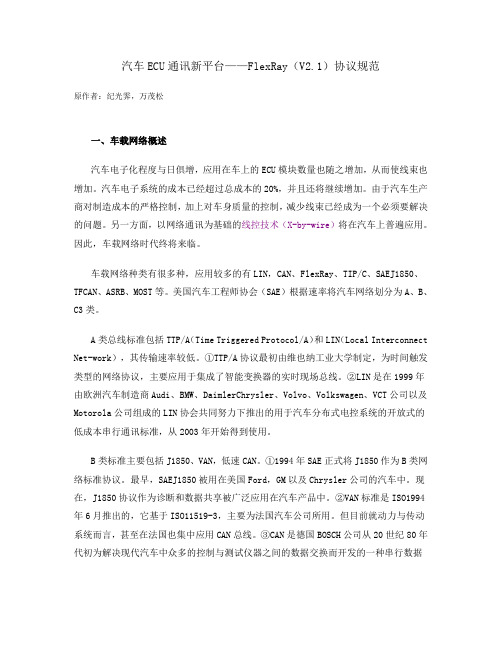
汽车ECU通讯新平台——FlexRay(V2.1)协议规范原作者:纪光霁,万茂松一、车载网络概述汽车电子化程度与日俱增,应用在车上的ECU模块数量也随之增加,从而使线束也增加。
汽车电子系统的成本已经超过总成本的20%,并且还将继续增加。
由于汽车生产商对制造成本的严格控制,加上对车身质量的控制,减少线束已经成为一个必须要解决的问题。
另一方面,以网络通讯为基础的线控技术(X-by-wire)将在汽车上普遍应用。
因此,车载网络时代终将来临。
车载网络种类有很多种,应用较多的有LIN,CAN、FlexRay、TIP/C、SAEJ1850、TFCAN、ASRB、MOST等。
美国汽车工程师协会(SAE)根据速率将汽车网络划分为A、B、C3类。
A类总线标准包括TTP/A(Time Triggered Protocol/A)和LIN(Local Interconnect Net-work),其传输速率较低。
①TTP/A协议最初由维也纳工业大学制定,为时间触发类型的网络协议,主要应用于集成了智能变换器的实时现场总线。
②LIN是在1999年由欧洲汽车制造商Audi、BMW、DaimlerChrysler、Volvo、Volkswagen、VCT公司以及Motorola公司组成的LIN协会共同努力下推出的用于汽车分布式电控系统的开放式的低成本串行通讯标准,从2003年开始得到使用。
B类标准主要包括J1850、VAN,低速CAN。
①1994年SAE正式将J1850作为B类网络标准协议。
最早,SAEJ1850被用在美国Ford,GM以及Chrysler公司的汽车中。
现在,J1850协议作为诊断和数据共享被广泛应用在汽车产品中。
②VAN标准是ISO1994年6月推出的,它基于ISO11519-3,主要为法国汽车公司所用。
但目前就动力与传动系统而言,甚至在法国也集中应用CAN总线。
③CAN是德国BOSCH公司从20世纪80年代初为解决现代汽车中众多的控制与测试仪器之间的数据交换而开发的一种串行数据通讯协议。
车内通信网络标准FlexRay的功能和特性分析

车内通信网络标准FlexRay的功能和特性分析FlexRay 标准在车内通信网络中具有较大优势和广泛的潜在应用机会。
本文详细地介绍了FlexRay 的数据速率、时钟同步等特性及可能的应用领域,并分析了FlexRay 的访问方法、时钟同步和群组启动等功能。
图1:几种汽车通信协议的成本和速率比较。
在FlexRay 协议制定5 年后,该协议规范的第二版(V2.1)在2005 年春季发布。
由于新技术能实现经济高效的新应用,整个行业对这个标准产生了浓厚的兴趣,本文将探讨该标准潜在的应用领域,详细地介绍在FlexRay 中使用的三种机制,并列举一系列实例来讨论FlexRay 的几种应用。
此外,本文还将讨论可行和不可行的拓扑结构,并简要论述唤醒群组(Cluster)的场景,以及讨论如何计算最优的消息帧大小。
FlexRay 的特性FlexRay 提供了传统车内通信协议所不具备的大量特性,包括: a. 2×10Mbps的数据速率FlexRay 支持两个通信信道,每个信道的速度达到10Mbps。
与CAN 协议相比,它能将可用带宽提高10-40 倍,具体大小取决于配置和对比模式的不同。
b. 同步时基FlexRay 中使用的访问方法是基于同步时基的。
该时基通过协议自动建立和同步,并提供给应用。
时基的精确度介于0.5μs和10μs之间(通常为1-2μs)。
图2:带静态和动态段的通信周期。
c.知道消息的到达时间通信是在不断循环的周期中进行的,特定消息在通信周期中拥有固定位置,因此接收器已经提前知道了消息到达的时间。
到达时间的临时偏差幅度会非常小,并能得到保证。
d. 冗余和非冗余通信为了增强系统的可用性,FlexRay 提供了冗余传输消息的选项。
消息能够冗余传输,但并不是所有消息都必须冗余传输,否则会导致带宽的过多损耗。
e. 灵活性在FlexRay 协议的开发过程中,关注的主要问题是灵活性。
不仅提供消息冗余。
- 1、下载文档前请自行甄别文档内容的完整性,平台不提供额外的编辑、内容补充、找答案等附加服务。
- 2、"仅部分预览"的文档,不可在线预览部分如存在完整性等问题,可反馈申请退款(可完整预览的文档不适用该条件!)。
- 3、如文档侵犯您的权益,请联系客服反馈,我们会尽快为您处理(人工客服工作时间:9:00-18:30)。
FlexRay Communications System Protocol Specification v2.1Revision AVersion 1DisclaimerThis document as released by the FlexRay Consortium is intended for the purpose of information only. The use of material contained in this document requires membership within the FlexRay Consortium or an agreement with the FlexRay Consortium. The FlexRay Consortium will not be liable for any unauthorized use of this Specification.Following the completion of the development of the FlexRay Communications System Specifications commercial exploitation licenses will be made available to End Users by way of an End User's License Agreement. Such licenses shall be contingent upon End Users granting reciprocal licenses to all Core Partners and non-assertions in favor of all Premium Associate Members, Associate Members and Devel-opment Members.All details and mechanisms concerning the bus guardian concept are defined in the FlexRay Bus Guardian Specifications.The FlexRay Communications System is currently specified for a baud rate of 10 Mbit/s. It may be extended to additional baud rates.No part of this publication may be reproduced or utilized in any form or by any means, electronic or mechanical, including photocopying and microfilm, without permission in writing from the publisher.The word FlexRay and the FlexRay logo are registered trademarks.Copyright © 2004-2006 FlexRay Consortium. All rights reserved.The Core Partners of the FlexRay Consortium are BMW AG, DaimlerChrysler AG, Freescale Halbleiter Deutschland GmbH, General Motors Corporation, Philips GmbH, Robert Bosch GmbH, and Volkswagen AG.Introduction1ScopeThe scope of the errata sheet is•to publish changes in the protocol specification between specification releases and•to document the changes from one release to the next.The documented changes must have a technical impact. Typing and spelling errors are not covered in this sheet. Grammatical corrections are only covered if the change may have a technical impact.2References[PS05]FlexRay Communications System - Protocol Layer Specification, v2.1, FlexRay Consortium, May 2005.[PS05A]FlexRay Communications System - Protocol Layer Specification, v2.1 Revision A, FlexRay Consortium, December 2005.[EPL05A]FlexRay Communications System - Electrical Physical Layer Specification, v2.1 Revision A, FlexRay Consortium, December 2005.3Notational ConventionsIn this document the same acronyms and abbreviations, notational conventions and SDL extensions are used as described and used in [PS05A].The item numbering is organized in the following way:<version number>.<item number>[.<sub item number>]The version number will be increased after every publication of the errata sheet. The item number is a consecutive number inside a version starting with “1”. The version and the item numbers of a published errata sheet will not change in later publications. Optional sub item numbers are used to document a complex change (e.g. more than one figure, table or paragraph was modified). The modifications belonging to one item have to be seen as a whole including all sub items.All entries in the errata sheet contain changes against the v2.1 revision A specification, not the specification as modified by previous errata. If an errata is modified by a later errata the original errata will remain in the document, but it will be marked as “superseded by errata X.Y”, which indicates the new errata. The new errata will be marked as “This errata supersedes errata Y.M and Z.N”.4Version HistoryRevision Date ItemsVersion 129-March-2006 1.01 - 1.02Table 1: Version history.Version 1Item 1.01Synopsis:TxD shall be HIGH after CAS/MTS transmissionLocation:[PS05A] Figure 3-18 on page 72Original:Replaced by:Notes: This errata entry is also valid for the FlexRay Protocol specification v2.1.Item 1.02Synopsis:Configuration of pChannelsLocation:[PS05A] section 9.3.1.1.2Original:1. the enumeration pChannels that indicates the channels to which the node is connected,Replaced by:26. the enumeration pChannels that indicates the channels to which the node is connected.The configuration of channels supported by the device, pChannels, has a unique characteristic in that it may affect significant hardware details of the implementation. It is expected that dual channel devices need to be able to support single channel operation, and that single channel devices are configurableto work on either channel A or channel B. As a result, it is required that an implementation be able to configure pChannels, but the ability to configure this more than once while the CC is in the power on state (see section 2.1.1) is not required. This mechanism does not need to be available in POC:config.A device may not, however, allow this parameter to be modified in the POC:ready, POC:normal active, POC:normal passive, or POC:halt states, or in any of the states that are defined in the WAKEUP and STARTUP macros of the POC process.Notes: The item was moved in the numbered list in section 9.3.1.1.2 from the first position (number 1) to the last position (number 26).This errata entry is also valid for the FlexRay Protocol specification v2.1 [PS05].。