摩托罗拉D2811HC, D2811C, D2812C ,D2813C中文说明书
电话机GE28112的详细说明书
GE28112子机和座机面板按健:TALK—开机SPKR—兔提REDIAL—重拨DEL—清除MEM—存储PROG—功能MUTE—静音–CID/VOL+--来电显示查询(VOL)—音量大小PAGE—呼叫对讲ANNOUNCE—录音ERASE—清除MEMO—家庭留言REVIW—上一条SKIP—下一条PLAY/STOP—播放/停止ANSWER ON/OFF—录音开关DAY/CHECK—改变时间HOUR—小时MIN—分钟电话使用功能:1.拨打电话:按下TALK开机健,听到拨号音后按下你所以拨打的号码,即可接通,通话完毕按下TALK键关闭即可.2.重拨:按下TALK通话健听到拨号音后,按一次REDIAL重拨健即可(注:只能重拨最后一组)3.存储号码:按一次MEM存储健,先输入储存的位置号码(0—10)再按一次MEM健,再次输入姓名(注:用英文输入)再按一次MEM键,再次输入号码,输入完毕再按一次MEM键确认即可,如要查询:先按一次MEM键然后用子机上的左右查询键翻阅即可.4.查看来电:在待机状态下直接按来电显示查询健即可,如要回拨此号码直接按TALK开机健即可.5.功能界面扩展诠释:按PROG功能健进入后用上下翻查健选择到HANDSETSETUP再按功能键PROG进入.1.SET LANGUAGE设置语言用功能健进进入,数字1-3选择即可(1为英语,2为法语,3为西班牙语)2.HANDSETNAME设置子机名称,进入后英文输入名字即可.3.RINGER TONE设置铃声种类,进入后按下下翻查键调节,最后按功能健确定退出.4.RINGER VOLUME设置铃声音量大小.5.VIP MELODY贵宾号码存储6.KEY TONE设置按健音开关1,ON表示开2,OFF表示关闭7.MESSAGE ALERT 设置留言提示音开关8.RING SELECT 设置录音响铃次数(3-6次)9.SECURITY CODE设置远程徭控听录音的密码10.AREA CODE 设置本地区号11.REGISTRATION 重设(对马,子机登入对马时用)12.DEREGISTRATION 为清除子机13.DEFAULITSETTING 子机设定恢复出厂状态录音功能设置:(座机操作):1.录制提示语:按住ANNOUNCE录音健不放,约两秒钟,听到‖嘀‖声后开始说话:比如:你好,你拨打的是我们家里的录音电话,现在主人不在,有事请留言,谢谢.‖说完后松手即可,如果要重录,再次重复上面的操作即可,满意为止.2.家庭录音:(此功能是为家人设计,如你要外出,给家人留言用)你可以按信MEMO不放,听到‖嘟‖一声后开始说话,完毕松手即可,如是家人回家看见显示窗有留言,直接按PLAY/STOP播放即可.3.清除留言;当你在听取留言时,如果要删除,在听取留言时直接按下ERASE清除键即可删除.如果你信箱里有多条留言,如果一条条的删除比较麻烦,这时你可以总清除,在待机状态下,按住ERASE 清除键不放,约2秒钟,即可全部删除,4.录音开关如果你不要录音功能,在座机的右侧ANSWER ON/OFF健,按一次显示窗显示‖---―说明关闭,在按一次为开启.5播放录音如显示窗显示有数字,数字代表有几条留言,在待机状态下按PLAY/STOP播放停止健即可,如果要跳跃或重听按REVIEW为上一条,SKIP为下一条,6调整时间(注.时间在中国走不准,因为电压频率不一样)按住座机右侧DAY/CHECK改变时间,调整星期几,按住HOUR为调整小时,调正确的时候在松手,按住MIN健为调整分钟,调整正确后松手即可.6.对码设置-本机售出均对好发货请勿自行对码,如需特别需要请向本店客服索要7.对讲功能:先按INT健然后再按1或2健,就表示和1子机或2子机对讲,当另一个子机响的时候再按另一子机的TALK就要以对讲了,通用28111 28112 DECT 6.0 无绳电话说明书一、话机设置(以下操作请在电话机处于待机状态下进行)房间监视:(此功能仅使用额外的手机上)按mute/program键进入主菜单,使用☐或❑键找到ROOM MONITOR选项;再按mute/program键进入ROOM MONITOR编辑,屏幕会显示ROOM MONITOR EXTENSION?;使用0~9数字键输入您想要被监控的手机名称或号码,被监控的手机会自动打开麦克风,而另一监控手机打开免提功能,自动监听来自被监控手机收集的声音。
UCC2813D-1中文资料

UCC2813-0/-1/-2/-3/-4/-5UCC3813-0/-1/-2/-3/-4/-5FEATURES100µA Typical Starting Supply Current 500µA Typical Operating Supply Current Operation to 1MHz Internal Soft Start Internal Fault Soft StartInternal Leading-Edge Blanking of the Current Sense Signal 1 Amp Totem-Pole Output70ns Typical Response fromCurrent-Sense to Gate Drive Output 1.5% Tolerance Voltage Reference Same Pinout as UCC3802, UC3842, and UC3842ADESCRIPTIONThe UCC3813-0/-1/-2/-3/-4/-5family of high-speed,low-power inte-grated circuits contain all of the control and drive components required for off-line and DC-to-DC fixed frequency current-mode switching power supplies with minimal parts count.These devices have the same pin configuration as the UC3842/3/4/5family,and also offer the added features of internal full-cycle soft start and internal leading-edge blanking of the current-sense input.The UCC3813-0/-1/-2/-3/-4/-5family offers a variety of package options,temperature range options,choice of maximum duty cycle,and choice of critical voltage levels.Lower reference parts such as the UCC3813-3and UCC3813-5fit best into battery operated systems,while the higher reference and the higher UVLO hysteresis of the UCC3813-2and UCC3813-4 make these ideal choices for use in off-line power supplies.The UCC2813-x series is specified for operation from –40°C to +85°C and the UCC3813-x series is specified for operation from 0°C to +70°C.BLOCK DIAGRAMLow Power Economy BiCMOSCurrent Mode PWMUDG-96134Part Number Maximum Duty CycleReference VoltageTurn-On ThresholdTurn-Off ThresholdUCCx813-0100%5V 7.2V 6.9V UCCx813-150%5V 9.4V 7.4V UCCx813-2100%5V 12.5V 8.3V UCCx813-3100%4V 4.1V 3.6V UCCx813-450%5V 12.5V 8.3V UCCx813-550%4V4.1V3.6VORDERING INFORMATIONCONNECTION DIAGRAMSVCC Voltage (Note 2). . . . . . . . . . . . . . . . . . . . . . . . . . .12.0V VCC Current. . . . . . . . . . . . . . . . . . . . . . . . . . . . . . . . .30.0mA OUT Current . . . . . . . . . . . . . . . . . . . . . . . . . . . . . . . . . . 1.0A OUT Energy (Capacitive Load). . . . . . . . . . . . . . . . . . .20.0µJ Analog Inputs (FB, CS). . . . . . . . . . . . . . . . . . . .–0.3V to 6.3V Power Dissipation at T A < +25°C (N Package). . . . . . . . . 1.0W Power Dissipation at T A < +25°C (D Package). . . . . . . .0.65W Storage Temperature . . . . . . . . . . . . . . . . . . .–65C to +150°C Junction Temperature. . . . . . . . . . . . . . . . . . .–55C to +150°C Lead Temperature (Soldering, 10 Seconds). . . . . . . . .+300°CABSOLUTE MAXIMUM RATINGS (Note 1)Note 1:All voltages are with respect to GND.All currents are positive into the specified terminal.Consult Unitrode Integrated Circuits databook for information regarding thermal specifica-tions and limitations of packages.Note 2:In normal operation VCC is powered through a current limiting resistor.Absolute maximum of 12V applies when VCC is driven from a low impedance source such that ICC does not exceed 30mA.UCCPACKAGETEMPERATURE RANGEPRODUCT OPTION ORDERING INFORMATIONTEMPERATURE RANGEPACKAGES UCC2813–40°C TO +85°C N, D,PW UCC38130°C TO +70°CN, D,PWELECTRICAL CHARACTERISTICS Unless otherwise stated, these specifications apply for –40°C ≤T A ≤+85°C forUCC2813-x; 0°C ≤T A ≤+70°C for UCC3813-x;VCC = 10V (Note 3); RT = 100k from REF to RC; CT=330pF from RC to GND;0.1µF capacitor from VCC to GND; 0.1µF capacitor from VREF to GND. T A =T J .PARAMETERTEST CONDITIONSUCC2813-x UCC3813-xUNITSMINTYPMAXReference Section Output Voltage T J = +25°C, I = 0.2mA, UCCx813-0/-1/-2/-4 4.925 5.00 5.075V T J = +25°C, I = 0.2mA, UCCx813-5 3.944.00 4.06V Load Regulation 0.2mA <I <5mA1030mV Total Variation UCCx813 -0-1/-2/-4 (Note 7) 4.84 5.00 5.10V UCCx813-5 (Note 7)3.844.00 4.08V Output Noise Voltage 10Hz ≤f ≤10kHz,T J = +25°C (Note 9)70µV Long Term Stability T A = +125C, 1000 Hours (Note 9)5mV Output Short Circuit –5–35mAOscillator Section Oscillator Frequency UCCx813-0/-1/-2/-4 (Note 4)404652kHz UCCx813-5 (Note 4)263136kHz Temperature Stability (Note 9)2.5%Amplitude Peak-to-Peak 2.25 2.40 2.55V Oscillator Peak Voltage2.45VELECTRICAL CHARACTERISTICS Unless otherwise stated, these specifications apply for –40°C≤T A≤+85°C for UCC2813-x; 0°C≤T A≤+70°C for UCC3813-x;VCC= 10V (Note 3); RT = 100k from REF to RC; CT=330pF from RC to GND;0.1µF capacitor from VCC to GND; 0.1µF capacitor from VREF to GND. T A=T J.PARAMETER TEST CONDITIONSUCC2813-xUCC3813-x UNITS MIN TYP MAXError Amplifier SectionInput Voltage COMP= 2.5V; UCCx813-0/-1/-2/-4 2.42 2.50 2.56VCOMP= 2.0V; UCCx813-3/-5 1.92 2.0 2.05V Input Bias Current–22µA Open Loop Voltage Gain6080dB COMP Sink Current FB = 2.7V,COMP= 1.1V0.4 2.5mA COMP Source Current FB = 1.8V,COMP= REF – 1.2V–0.2–0.5–0.8mA Gain Bandwidth Product(Note 9)2MHz PWM SectionMaximum Duty Cycle UCCx813-0/-2/-39799100%UCCx813-1/-4/-5484950 Minimum Duty Cycle COMP= 0V0% Current Sense SectionGain(Note 5) 1.10 1.65 1.80V/V Maximum Input Signal COMP= 5V (Note 6)0.9 1.0 1.1V Input Bias Current–200200nA CS Blank Time50100150ns Over-Current Threshold 1.32 1.55 1.70V COMP to CS Offset CS = 0V0.450.90 1.35V Output SectionOUT Low Level I = 20mA, all parts0.10.4VI = 200mA, all parts0.350.90VI = 50mA,VCC= 5V, UCCx813-3/-50.150.40VI = 20mA,VCC= 0V, all parts0.7 1.2VOUT High V SAT (V CC-OUT)I = –20mA, all parts0.150.40V I = –200mA, all parts 1.0 1.9V I = –50mA,VCC= 5V, UCCx813-3/-50.40.9VRise Time C L= 1nF4170ns Fall Time C L= 1nF4475ns Undervoltage Lockout SectionStart Threshold (Note 8)UCCx813-0 6.67.27.8VUCCx813-18.69.410.2VUCCx813-2/-411.512.513.5VUCCx813-3/-5 3.7 4.1 4.5V Stop Threshold (Note 8)UCC1813-0 6.3 6.97.5VUCC1813-1 6.87.48.0VUCCx813-2/-47.68.39.0VUCCx813-3/-5 3.2 3.6 4.0V Start to Stop Hysteresis UCCx813-00.120.30.48VUCCx813-1 1.62 2.4VUCCx813-2/-4 3.5 4.2 5.1VUCCx813-3/-50.20.50.8VELECTRICAL CHARACTERISTICS Unless otherwise stated, these specifications apply for –40°C≤T A≤+85°C for UCC2813-x; 0°C≤T A≤+70°C for UCC3813-x;VCC= 10V (Note 3); RT = 100k from REF to RC; CT=330pF from RC to GND;0.1µF capacitor from VCC to GND; 0.1µF capacitor from VREF to GND. T A=T J.PARAMETER TEST CONDITIONSUCC2813-xUCC3813-x UNITS MIN TYP MAXSoft Start SectionCOMP Rise Time FB = 1.8V, Rise from 0.5V to REF–1V4ms Overall SectionStart-up Current VCC< Start Threshold0.10.23mA Operating Supply Current FB = 0V, CS = 0V, RC = 0V0.5 1.2mA VCC Internal Zener Voltage ICC = 10mA (Note 8)1213.515V VCC Internal Zener Voltage Minus StartThreshold VoltageUCCx813-2/-40.5 1.0VNote 3: Adjust VCC above the start threshold before setting at 10V.Note 4: Oscillator frequency for the UCCx813-0, UCCx813-2 and UCCx813-3 is the output frequency.Oscillator frequency for the UCCx813-1, UCCx813-4 and UCCx813-5 is twice the output frequency.Note 5: Gain is defined by:A VVV V COMPCSCS≤≤008..Note 6: Parameter measured at trip point of latch with Pin 2 at 0V.Note 7: Total Variation includes temperature stability and load regulation.Note 8: Start Threshold, Stop Threshold and Zener Shunt Thresholds track one another. Note 9: Guaranteed by design. Not 100% tested in production.COMP:COMP is the output of the error amplifier and the input of the PWM comparator.Unlike other devices,the error amplifier in the UCC3813 family is a true,low output-impedance,2MHz operational amplifier.As such,the COMP terminal can both source and sink current.However,the error amplifier is internally current limited,so that you can command zero duty cycle by externally forcing COMP to GND.The UCC3813family features built-in full cycle Soft Start. Soft Start is implemented as a clamp on the maximum COMP voltage.FB:FB is the inverting input of the error amplifier.For best stability,keep FB lead length as short as possible and FB stray capacitance as small as possible.CS:CS is the input to the current sense comparators. The UCC3813family has two different current sense comparators:the PWM comparator and an over-current comparator.The UCC3813family contains digital current sense filter-ing,which disconnects the CS terminal from the current sense comparator during the100ns interval immediately following the rising edge of the OUT pin.This digital filter-ing,also called leading-edge blanking,means that in most applications,no analog filtering(RC filter)is re-quired on pared to an external RC filter tech-nique,the leading-edge blanking provides a smaller effective CS to OUT propagation delay.Note,however, that the minimum non-zero On-Time of the OUT signal is directly affected by the leading-edge-blanking and the CS to OUT propagation delay.The over-current comparator is only intended for fault sensing,and exceeding the over-current threshold will cause a soft start cycle.RC:RC is the oscillator timing pin.For fixed frequency operation,set timing capacitor charging current by con-necting a resistor from REF to RC.Set frequency by con-necting a timing capacitor from RC to GND.For best performance,keep the timing capacitor lead to GND as short and direct as possible.If possible,use separate ground traces for the timing capacitor and all other func-tions.PIN DESCRIPTIONSThe frequency of oscillation can be estimated with the following equations:UCCx813-0/-1/-2/-4:F R C=•15.UCCx813-3, UCCx813-5:F R C=•10.where frequency is in Hz,resistance is in Ω,and capaci-tance is in farads.The recommended range of timing re-sistors is between 10k and 200k and timing capacitor is 100pF to 1000pF .Never use a timing resistor less than 10k.GND:GND is reference ground and power ground for all functions on this part.OUT:OUT is the output of a high-current power driver capable of driving the gate of a power MOSFET with peak currents exceeding ±750mA.OUT is actively held low when VCC is below the UVLO threshold.The high-current power driver consists of FET output de-vices,which can switch all of the way to GND and all of the way to VCC.The output stage also provides a very low impedance to overshoot and undershoot.This means that in many cases,external schottky clamp diodes are not required.VCC:VCC is the power input connection for this device.In normal operation VCC is powered through a current limiting resistor.Although quiescent VCC current is verylow,total supply current will be higher,depending on OUT current.Total VCC current is the sum of quiescent VCC current and the average OUT current.Knowing the operating frequency and the MOSFET gate charge (Qg),average OUT current can be calculated from:I Q F OUT g =•.To prevent noise problems,bypass VCC to GND with a ceramic capacitor as close to the VCC pin as possible.An electrolytic capacitor may also be used in addition to the ceramic capacitor.REF:REF is the voltage reference for the error amplifier and also for many other functions on the IC.REF is also used as the logic power supply for high speed switching logic on the IC.When VCC is greater than 1V and less than the UVLO threshold,REF is pulled to ground through a 5k Ωresis-tor.This means that REF can be used as a logic output indicating power system status.It is important for refer-ence stability that REF is bypassed to GND with a ce-ramic capacitor as close to the pin as possible.An electrolytic capacitor may also be used in addition to the ceramic capacitor.A minimum of 0.1µF ceramic is re-quired.Additional REF bypassing is required for external loads greater than 2.5mA on the reference.To prevent noise problems with high speed switching transients,bypass REF to ground with a ceramic capaci-tor very close to the IC package.PIN DESCRIPTIONS (cont.)APPLICATION INFORMATION4.003.983.963.943.923.903.883.863.843.8244.24.44.64.855.25.45.65.86V (V)CC V (V )R E F Figure 5.UCC3813-3/-5V REF vs.V CC ;I LOAD= 0.5mA.APPLICATION INFORMATION (cont.)T and C T.R T and C T .oscillator frequency.oscillator frequency.CC APPLICATION INFORMATION (cont.)CCCS = 0V.T T UNITRODE CORPORA TION7 CONTINENTAL BLVD.• MERRIMACK, NH 03054TEL.(603) 424-2410 • FAX (603) 424-3460IMPORTANT NOTICETexas Instruments and its subsidiaries (TI) reserve the right to make changes to their products or to discontinue any product or service without notice, and advise customers to obtain the latest version of relevant information to verify, before placing orders, that information being relied on is current and complete. All products are sold subject to the terms and conditions of sale supplied at the time of order acknowledgement, including those pertaining to warranty, patent infringement, and limitation of liability.TI warrants performance of its semiconductor products to the specifications applicable at the time of sale in accordance with TI’s standard warranty. Testing and other quality control techniques are utilized to the extent TI deems necessary to support this warranty. Specific testing of all parameters of each device is not necessarily performed, except those mandated by government requirements.CERTAIN APPLICATIONS USING SEMICONDUCTOR PRODUCTS MAY INVOLVE POTENTIAL RISKS OF DEATH, PERSONAL INJURY, OR SEVERE PROPERTY OR ENVIRONMENTAL DAMAGE (“CRITICAL APPLICATIONS”). TI SEMICONDUCTOR PRODUCTS ARE NOT DESIGNED, AUTHORIZED, OR WARRANTED TO BE SUITABLE FOR USE IN LIFE-SUPPORT DEVICES OR SYSTEMS OR OTHER CRITICAL APPLICATIONS. INCLUSION OF TI PRODUCTS IN SUCH APPLICATIONS IS UNDERSTOOD TO BE FULLY AT THE CUSTOMER’S RISK.In order to minimize risks associated with the customer’s applications, adequate design and operating safeguards must be provided by the customer to minimize inherent or procedural hazards.TI assumes no liability for applications assistance or customer product design. TI does not warrant or represent that any license, either express or implied, is granted under any patent right, copyright, mask work right, or other intellectual property right of TI covering or relating to any combination, machine, or process in which such semiconductor products or services might be or are used. TI’s publication of information regarding any third party’s products or services does not constitute TI’s approval, warranty or endorsement thereof.Copyright © 1999, Texas Instruments Incorporated。
TH2811C12C说明书

使用说明书O P E R A T I O N M A N U A LM O D E LC h a n g z h o u T o n g h u i E l e c t r o n i c C o . , L t d . 地址址::江江苏苏省省常常州州市市新新北北区区天天山山路路33号号 电话话::((00551199))5132222,,5113342 传真真::((0519))55110099997722 邮箱箱::S S a a l l e e s s @@t t o o n n g g h h u u i i c c o o ..c c o o m m 网址址::h h t t t t p p :://// w w w w w w ..t t o o n n g g h h u u i i ..c c o o m ..c c n n m目录第一章概述 11.1 引言 11.2 主要技术指标 11.3 主要功能 31.4 仪器结构及安装 41.5 工作环境 6 第二章操作说明72.1 注意事项 72.2 操作步骤 72.2.1 电源72.2.2 连接被测电容72.2.3 测量条件82.2.3.1 频率 82.2.3.2 显示.、量程和量程保持 82.2.3.3 等效方式 82.2.3.4 清“0”功能(校准) 9 第三章维护103.1 仪器误差概述 103.2 用户维修 113.2.1 注意事项113.2.2 仪器性能检查113.2.3 故障分析123.2.4 仪器信号检查133.2.5 基准 14 第四章成套及保修154.1 成套 154.2 保修 15第一章 概述- 1 -第一章 概述1.1 引言TH2812C / TH2811C 型LCR 数字电桥是一种以微处理技术为基础的自动测量电感量L 、电容量C 、电阻值R 、品质因数Q 、损耗角切值D的智能元件参数测量仪器,其0.25%的基本精度和高分辨率的显示对于元件测量的质量和可靠性的提高将有莫大的帮助。
摩托罗拉 MOTOTRBO 专业系列无线通信设备配件目录说明书

MOTOTRBO™PROFESSIONAL SERIES RADIO ACCESSORIES T HE POWER OF YOUR RADIO UNLEASHEDXiR P8200 SERIES Remote Speaker Microphones6 –7 Remote Speaker Microphones-Accessories with standard 3.5mm8 Remote Speaker Microphones-Accessories with threaded 3.5mm9 – 10 Public Safety Microphones10 – 11 Surveillance Accessories and earpieces 12 – 15 Surveillance Accessories Replacement Kits 16, 18 Earpieces 20 – 23 Headsets 24 – 25 Tactical24 – 25 Motorola Orginal® Two-way Radios Batteries 36 – 37 Charger Solutions42 Vehicular and Travel Chargers 45 Impres Battery Management Tools 45 Carry Solutions 47 – 49 Antennas51 – 52Programming Cables58XiR P8600 / P8600i SERIES Remote Speaker Microphones6 –7 Remote Speaker Microphones-Accessories with standard 3.5mm8 Remote Speaker Microphones-Accessories with threaded 3.5mm9 – 10 Surveillance Accessories and earpieces 12 – 15 Surveillance Accessories Replacement Kits 16, 18 Earpieces 20 – 23 Headsets 24 – 25 Tactical24 – 25 MagOne Accessories24 – 25 Operational Critical Wireless Bluetooth ® Accessories 28 – 35 Wireless Replacements Kits34 Motorola Orginal® Two-way Radios Batteries 38 – 41 Charger Solutions42 Vehicular and Travel Chargers 45 Impres Battery Management Tools 45 Carry Solutions 46, 48 – 50 Antennas53, 55 – 56Antennas Accessories 57Programming Cables58XiR P8600EX SERIES Remote Speaker Microphones 8 – 9 Remote Speaker Microphones-Accessories with standard 3.5mm 8 3M Peltor Headsets 26 – 27 Motorola Orginal ® Two-way Radios Batteries 40 – 41 Charger Solutions 42 Carry Solutions46, 49 – 50Antennas54XiR P6600 / P6600i SERIES Remote Speaker Microphones 8 – 9 Remote Speaker Microphones-Accessories with standard 3.5mm 8 Surveillance Accessories and earpieces 14 – 15 Surveillance Accessories Replacement Kits 16 Earpieces 20 – 21 MagOne Accessories20 – 21Headsets 22 – 23 Motorola Orginal ® Two-way Radios Batteries 36 – 39 Charger Solutions 42 Vehicular and Travel Chargers 45 Impres Battery Management Tools 45 Carry Solutions 47, 49 – 50 Antennas 53, 55 Antennas Accessories 57 Programming Cables58PAGESXiR E8600 / E8600i SERIES Remote Speaker Microphones 8 – 9Remote Speaker Microphones-Accessories with standard 3.5mm 8 Surveillance Accessories and earpieces 14 – 15 Surveillance Accessories Replacement Kits 16 MagOne Accessories 20 – 21 Headsets 22 – 23 Motorola Orginal® Two-way Radios Batteries 40 – 41 Charger Solutions 44 – 45 Carry Solutions46 Antennas 55SL1K/SL2K SERIES Surveillance Accessories and earpieces 14 – 15 Surveillance Accessories Replacement Kits 16, 18 Earpieces 20 – 21 Operational Critical Wireless Bluetooth® Accessories 28 – 35 Wireless Replacements Kits 34 Charger Solutions 44 Carry Solutions49 Antennas 56 Antennas Accessories 57 Programming Cables58XiR M8200 SERIES Microphones 61 Mobile Microphone Accessories 62 External Push-To-Talk(PTT) 63 Operational Critical Wireless Bluetooth® Accessories 64 – 67 Replacement Parts and Secondary Audio Accessories 67 Control Station Accessories 71 Installation and Mounting Accessories 72 External Speakers 73 Cables 74 – 75 Antennas 76 – 81XiR M8660 / M8660i Microphones 60 – 61Mobile Microphone Accessories 62 External Push-To-Talk(PTT) 63 Operational Critical Wireless Bluetooth® Accessories 64 – 69 Replacement Parts and Secondary Audio Accessories 66 – 67, 70Control Station Accessories 71 Installation and Mounting Accessories 72 External Speakers73Cables 74 – 75Antennas 76 – 81XiR M6600 SERIES Microphones 61 Mobile Microphone Accessories 62 External Push-To-Talk(PTT) 63 Installation and Mounting Accessories 72 – 73 External Speakers73 Cables 75Antennas76 – 81PAGESIMPRES ™ BATTERIES AND CHARGERS: YOUR BATTERY , SAFER, SMARTER, POWERED FOR LONGERGet rid of the guesswork and get more from every battery.Get the most out of every battery and eliminate the surprise of “low battery alerts”. IMPRES chargers tell you exactly how much capacity is in an IMPRES battery before you attach it to your radio and exactly when an IMPRES battery has reached the end of service life.Enjoy 43% longer battery life from IMPRES over non-IMPRES batteries – without spending maintenance or record keeping time and effort. With IMPRES Battery Fleet ManagementSoftware, you can check the status of 25 or 25,000 batteries at a glance, from one computer.IMPRES ™ AUDIOMake sure every word is heard regardless of the level or direction you’re speaking into the accessory. Be clearly heard the first time and eliminate repeating yourself. Whether you need to talk loudly or quietly, into or away from theaccessory, IMPRES Audio lowers the loud talker level and raises the soft talker level automatically so listeners do not have to adjust the volume depending on who is talking.Policing a busy airport, fixing equipment on a noisy production floor or assisting guests in a quiet hotel, IMPRES Audio promises a high quality communication experience. > Experience IMPRES AudioWINDPORTINGCommunicate clearly in difficult weather. Wherever you work – in howling wind, driving rain, and severe weather – Windporting helps you communicate effectively and listeners hear clearly.Windporting technology eliminates the whining and howling sounds of wind blowing across your lapel/remote speaker microphone. It also prevents water from clogging the microphone for clearer transmissions. > Hear the difference Windporting makesINTELLIGENT AUDIOFocus on your job instead of your radio volume. Make adjusting your radio volume based on background noise a thing of the past. Intelligent Audio listens to sounds in the background and automatically raises or lowers your radio volume so you can always hear. If you’re heading from a noisy area to a quiet place, you won’t disturb others because you forgot to adjust the volume.Intelligent Audio when complemented with IMPRES Audio takes your communications to a new level. > See Intelligent Audio in actionOPERATIONS CRITICAL WIRELESS: YOUR RADIO, UNLEASHEDWork with your radio like never before. Place your radio on a desk or cart, in a purse, medical bag or backpack and converse seamlessly with your wireless earpiece up to 10m away from your radio. Put your wireless PTT where you want to – on a clipboard, steering wheel or coat pocket – without wires getting in the way. Motorola Bluetooth enabled radios allow both an Operations Critical Wireless PTT and audio accessory to be connected and used at the same time. And Operations Critical Wireless accessories last up to 10 hours – up to 3 times the battery life of commercial Bluetooth ® headsets.MOTOTRBO radios are already best in class, but to help you work at your best, you needenhancements targeted to your specific workplace. We’ve developed a line of accessories with unique features designed to optimize the performance of your radio in your work environment,unleashing the full power of the industry’s most advanced digital radio platform.XiR P6600 SERIES XiR P6600i SERIES XiR P8600 Ex SERIES XiR E8600 SERIES XiR E8600i SERIES XiR P8200 SERIES XIR P8600 SERIES XIR P8600i SERIES SL1K SERIES SL2K SERIESPROGRAMMABLE BUTTON: This programmable button allows you to access key features while you keep your radio on your belt or hidden under a jacket.IP RATING: The international standard for rating dust and water protection. Thefirst digit represents the level of dust protection: 5 provides excellent protection fromdust. The second digit represents water protection. IP54 provides protection fromwater sprayed from all directions, IP55 protects against driving rain, and IP57 resistssubmersion in 1 meter of fresh water for 30 minutes.INTRINSIC SAFETY RATING: Motorola-approved accessories are a critical part of theoverall radio system certified by a recognized testing organization as intrinsically safe.Non-Motorola approved accessories may not be certified for MOTOTRBO and if used,could result in equipment that is NOT approved or unsafe in a hazardous environment.**NOTE: TIA = TIA4950 Intrinsic Safety Rating; FM = FM 1988 Intrinsic Safetyrating Accessories with these ratings are approved for FM or TIA when connected toIntrinsically safe FM or TIA radio/battery system.XiR P8200 XiR P8600XiR P8200REMOTE XiR P8600XiR P6600XiR E8600 XiR P8600 Ex RSM ACCESSORIESAUDIOXiR P8200XiR P8200XiR P8200XiR P8600IMPRES AUDIO (MOTOROLA EXCLUSIVE): Ensure your voice is heard clearer, crisper, and louder regardless of level or direction you’re speaking into the accessory. INTELLIGENT AUDIO (MOTOROLA EXCLUSIVE): Set your volume once. Dependon your accessory to listen for changes in background noise, adjusting the volume automatically so you hear every call.MICROPHONE AND PTT: Some accessories have a microphone on the same wireas push-to-talk (2-wire surveillance kit) or on a separate wire (3-wire surveillance kits).Microphones are small, easy to mount and hide during surveillance operations, yetpowerful enough to pick up whispered transmissions and reduce ambient noise.PROGRAMMABLE BUTTON: This programmable button allows you to access keyfeatures while you keep your radio on your belt or hidden under a jacket.INTRINSIC SAFETY RATING: Motorola-approved accessories are a critical part of theoverall radio system certified by a recognized testing organization as intrinsically safe.Non-Motorola approved accessories may not be certified for MOTOTRBO and if used,could result in equipment that is NOT approved or unsafe in a hazardous environment.XiR P8200 XiR P8600HOW DOES IMPRES IMPROVE AUDIO PERFORMANCE? IMPRES enhances the clarity and audio quality of Motorola accessories by reducingambient noise and improving voice intelligibility.If you speak quietly or normally, but not directly into a microphone, IMPRES Audio detects changes in your voice and automatically adjusts the transmitted volume so your listener won’t have to adjust volume up and down.> Experience IMPRES audioXiR P6600XiR P6600XiR P8200XiR P8600XiR E8600XiR P8600XiR P8200XiR P8600SL1KHOW DO TEMPLETRANSDUCERS WORK?These headsets use transducers that rest on your temple to convert audio into sound vibration and transmit it to your inner ear. If you’re using hearing protection or directing heavy traffic, you can hear the audio from your radio and the surrounding environment. Since the transducer sits in front of your ears, you can also wear earplugs and still hear the radio.XiR P6600E8600 SL1KXiR P6600XiR P6600E8600XiR P8600XiR P8200 XiR P8600XiR P8200 XiR P8600 XiR P8600XiR P8600 ExXiR P8600 ExSINGLE NOISE RATING: Signal-to-noise ratio (often abbreviated SNR or S/N) is a measure used in science and engineering that compares the level of a desired signal to the level of background noise. It is defined as the ratio of signal power to the noise power, often expressed in decibels.MICROPHONE AND PTT: Some accessories have a microphone on the same wire as push-to-talk (2-wire surveillance kit) or on a separate wire (3-wire surveillance kits). Microphones are small, easy to mount and hide during surveillance operations, yet powerful enough to pick up whispered transmissions and reduce ambient noise.EARPIECE TYPE: Choose the right fit for your operations – a simple, low cost, discreet earbud or the rugged, high performance CommPort™ style earpiece.MICROPHONE: The in-line microphone on the earbud earpiece is designed for generaluse, while the directional microphone on the CommPort™ style earpiece is ideal for lowernoise environments.OPERATIONS CRITICAL/ENHANCED OPERATIONS CRITICAL: This Bluetooth®solution specifically for businesses features simple pairing, high quality audio and fastpush-to-talk to ensure every word is transmitted. Enhanced Operations Critical Wirelesshas all this, plus instant pairing with just a touch of the accessory to the radio’s Bluetoothadapter, and intrinsically safe certification for hazardous environments. This meansmultiple workers on shifts who need grab-and-go device can all pair at the same timewithout connecting to the wrong radio.XiR P8200 XiR P8600 SL1KXiR P8200XiR P8600SL1K*Note: PTT on radio or with separate wireless PTT. All blue tooth kits require in country type approvals.Note: SL series and XiR P8600 / P8600i series portable radios have Bluetooth embedded in the radio and do not require a separate external adapter.XiR P8200 XiR P8600 SL1KIMPRES BATTERIES AND CHARGERS: Get the most out of every battery andeliminate the surprise of “low battery alerts”. IMPRES chargers tell you exactly how much capacity is in an IMPRES battery before you attach it to your radio and exactly when an IMPRES battery has reached the end of service life.INTRINSIC SAFETY RATING: Motorola-approved batteries are a critical part of the overall radio system certified by a recognized testing organization as intrinsically safe. Non-Motorola approved batteries may not be certified for MOTOTRBO and if used, could result in equipment that is NOT approved or unsafe in a hazardous environment.XiR P8200P6600P6600LOW VOLTAGE BATTERIESWhen paired with the enhanced 'e' series radiosLow Voltage Batteries (PMNN4488, PMNN4499,PMNN4489, PMNN4490, PMNN4493) deliver up to28 hours of battery talk time. Working up to 3 shifts,these new batteries are similar size and weight ascurrent batteries.MOTOTRBO PORTABLE RADIOSSL1KXiR E8600MOTOTRBO PORTABLE RADIOSIMPRES BATTERYMANAGEMENT TOOLS?With the unique IMPRES Battery Reader and IMPRES Battery Fleet Management systems, efficiently manage your batteries with real-time data not available with other manufacturers’ batteries. Our easy-to-use software applications show you if there is enough capacity for a full shift, alert you to low capacity batteries, prevent downtime and eliminate throwing batteries out prematurely.Now over-the-air capable withXiR P8600 / P8600i and P6600 / P6600i with IMPRES batteriesIMPRES BATTERY FLEET MANAGEMENT SOFTWARE REPORTSIMPRES BATTERY FLEET MANAGEMENTACTIVE BATTERY REPORTIMPRES BATTERY DATA READER, GENERAL INFORMATION SCREEN* Must be C revision or greater for compatibility with XiR P6600 / P6600i series and XiR P8600 / P8600i series radios.XiR P6600 XiR P8600 ExXiR E8600SL1KXiR E8600* Must be C revision or greater for compatibility with XiR P6600 / P6600i series and XiR P8600 / P8600i series radios.XiR P8600XiR P8600 Ex MATERIAL: Choose from comfortable and flexible nylon cases, rugged, durable hard leather cases or carry holsters.SWIVEL OR FIXED LOOP: Secure to a belt loop and the case swings freely from side to side. The swivel latch system also allows the radio and case to be removed from the belt loop by simply inverting, lifting it up and out of the belt loop. Fixed loops provide a sturdy attachment to your belt.XiR P8200XiR P6600XiR P8200 XiR P8600XiR P6600 SERIESXiR P8600 XiR P8200 SL1KXiR P8600 ExXiR P6600 XiR P8200 XiR P8600XiR P8200INTEGRATED GPS: A GPS antenna is integrated into the RF antenna. (The XiR P6600 / P6600i series radios do not have GPS capability, but use these antennas.) FREQUENCY BAND: Most antennas only cover a portion of a frequency band. Our wideband UHF and VHF antennas offer coverage across the entire band, enhancing your communication flexibility.XiR P6600XiR P8200XiR P8600XiR P8600 Ex XiR P6600XiR P8600XiR E8600SERIESXiR P6600XiR P8600XiR P8600SL1KMOTOTRBO PORTABLE RADIOSUNRIVALED VOICE AND DATA ON THE GO XiR M8600 / XiR M8600i SERIESThe XiR M8600 series shares the same connector as the XiR M8200 series accessories enabling easy migration. This portfolio is enhanced with integrated Bluetooth ®, giving more flexibility than ever before. Now your drivers can check on packages or walk around the loading dock and stay connected within 10m of their radio. A new IMPRES keypad microphone features a four-way navigation button that makes accessing critical features on the large color display, dialing phone numbers and sending text messages easy.INTEGRATED VOICE AND DATA ON THE GO XiR M8200 SERIESHandling dispatch for a delivery company or hauling freight across the country, accessories must meet challenging installation and operational requirements. XiR M8200 series mobile accessories are specifically designed for hassle-free communication in a vehicle, for dispatch-enabled communication, and for easy installation.XiR M6600 SERIESThe XiR M6600 features a durable telco accessory connector that enables microphones, external speakers and vehicular solutions. Many of the XiR M6600 microphones feature Intelligent Audio. Intelligent Audio listens to sounds in the background and automatically raises or lowers your radio volume so you can always hear clearly. If you’re driving an empty bus that quickly fills with chattering children – you will still be able to hear important communication without taking your hands off the wheel to adjust the radio volume.XiR M8200 SERIESXiR M8600 SERIES XiR M8600i SERIESXiR M6600 SERIESSL1K XiR P8200XiR P8600XiR P6600XiR M8660HOW CAN I COMMUNICATE SAFELY IN MY VEHICLE?The IMPRES Visor Microphone mounts to your vehicle’s visor for safe, convenient communication. Press the external push-to-talk button on the steering wheel to converse without taking your hands off the wheelor your eyes off the road. IMPRES Audio compensates for the distance of the visor mic from your mouth so that your radio communications are loud and clear.XiR M8600XiR M8600LONG RANGE WIRELESS SOLUTIONSDesigned for customers who depend on their high power mobile radio for system connection but must work outside of their vehicle. The Long Range Wireless solution allows you to maintain critical communications even on remote job site.MAINTAIN CRITICAL COMMUNICATIONS EVEN ON REMOTE JOB SITESSITUATIONKeep in touch even on remote job sites when you depend on your high power mobile radio but have to work outside your vehicle. You are a utility worker and need to check the meter readings. You have to park your truck about 100 meters away from the utility box due to access restrictions, yet you stay connected to your radio with your Long Range Wireless Remote Speaker Microphone. You communicate key readings immediately to dispatch. Get your job done safely and more efficiently.SOLUTIONThe Long Range Wireless Remote Speaker Microphone (RSM) pairs instantly with touch pairing to the mobile microphone with Bluetooth gateway. The Bluetooth microphone is compatible with MOTOTRBO XiR M8200 and XiR M8600 / M8600i series mobile radios. The Long Range Wireless RSM works up to 100 meters away from the mobile radio, keeping you in communication where you never thought possible.XiR M8600EARPIECE TYPE: Choose the right fit for your operations – a simple, low cost, discreet earbud or the rugged, high performance CommPort ™style earpiece.Note: XiR M8660 / M8660i series mobile radios have Bluetooth embedded in the radio. *Note: PTT on radio or with separate wireless PTT.MICROPHONE: The in-line microphone on the earbud earpiece is great for general use, while the directional microphone on the CommPort ™ style earpiece is ideal for lower noise environments.HOW DO MOBILE WIRELESS ACCESSORIES HELP ME?Use your mobile radio like never before and freely move around your vehicle. This means a driver can sort through packages on the back of the delivery truck, a bus driver can check on students in the back of the bus, or a city worker can trim trees from a cherry picker and all can still remain connected to their mobile radio. And by removing the wired connection to a desktop mobile, a dispatcher can walk around the office and manage calls.XiR M8600XiR M8600XiR M8600XiR M8600 XiR M8600XiR M8600XiR M8600XiR M8600XiR M8600FREQUENCY BAND: Most antennas only cover a portion of a frequency band. Our wideband UHF and VHF antennas offer coverage across the entire band, enhancing your communication flexibility. INTEGRATED GPS: To support GPS capability in the radio, the GPS antenna is integrated into the RF antenna.XiR M8600 XiR M8600XiR M8600XiR M8600XiR M8600XiR M8600XiR M8600MOTOTRBO MOBILE RADIOSXiR M8600XiR M8600XiR M8600 XiR M8600For more information on Motorola accessories,visit /ap/mototrboMOTOROLA, MOTO, MOTOROLA SOLUTIONS and the Stylized M Logo are trademarks or registered trademarks of Motorola Trademark Holdings, LLCand are used under license. All other trademarks are the property of their respective owners. © 2016 Motorola Solutions, Inc. All rights reserved.GLOBAL_ACCE_CAT_AP_1116Motorola Solutions Singapore Pte Ltd12 Ang Mo Kio Street 64, Ang Mo Kio Industrial Park 3, UE Biz Hub, Block A, Level 7 Singapore 569088。
摩托罗拉CL10xC系列子母机说明书
座机............................................................................................17
3. 使用座机............................................................................17
此说明书可提供您所需的一切信息,帮助您充分利用本 电话机的功能。
要设置您的电话,请遵循后面几页“使用前的准备”中 的简单指示。
重要信息 仅使用自带的电话线。 下列配件齐全吗? • 座机
• 手柄和曲线
• 座机的电源适配器
摩托罗拉canopy配置说明书
摩托罗拉 CANOPY 配置说明书
选择左边的 IP configuration 选项,进入下面页面。 给模块设置规划好的 IP 地址、 子网掩码、网关。然后保存,重新启动模块。
在 IE 浏览器里输入更改后的 IP 地址登陆 SM 模块,如果有相对应的 AP 模块的话
Page 9 of 18
Page 12 of 18
摩托罗拉 CANOPY 配置说明书 项,其他情况下都选择默认的第三个选项。给模块选择一个规划好的频率(主、从端的 频率必须相同)。给模块设定一个上下行速率(只在 BH 主端设定,BH 从端自适应)。 给模块选择一个颜色代码(BH 主端和 BH 从端的颜色代码必须相同才能通信)。往下 拉动下拉条。点击保存改动。
选择左边的 IP configuration 选项,进入下面页面。给设备设置已规划好的 IP 地址、 子网掩码、网关。然后保存改动,重新启动设备。
配置 从端 CANOPY BH10 在室内连接好设备,等设备启动后,在 IE 浏览器里面输入设备的默认 IP 地址:
169.254.1.1 进入设备首页面。BH 模块默认都是从端。 点击左边的 configuration 选项,进入下面页面。 给模块设置规划好的频率(与主
摩托罗拉 CANOPY 配置说明书 (AP-SM 的频率、颜色代码配置相同),会在首页面看到信号强度值(室内不用对准 模块或瞄准)如下图:
在 SM 端能 PING 通、访问 AP 设备,但在 AP 端不能 PING 通 SM 设备,但能够 通过通道来访问 SM 端设备。 配置 主端 CANOPY BH10
Page 3 of 18
摩托罗拉 CANOPY 配置说明书
在所有的情况之下,当配置参数被修改之后,改动必须被保存并且设备必 须重新启动。当模块上电或在 Web 管理页面中 reboot 以后,模块需要 25 秒左右的时 间启动。在启动期间,进行自检测试和其他检测。
SG2813中文资料
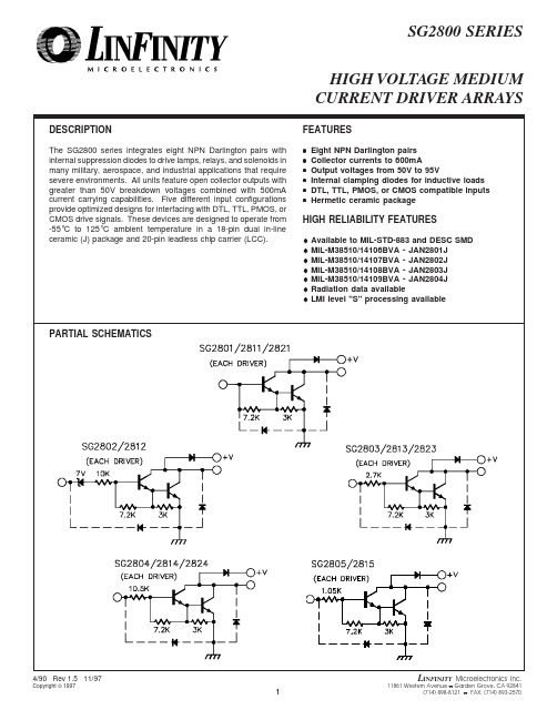
DESCRIPTIONThe SG2800 series integrates eight NPN Darlington pairs with internal suppression diodes to drive lamps, relays, and solenoids in many military, aerospace, and industrial applications that require severe environments. All units feature open collector outputs with greater than 50V breakdown voltages combined with 500mA current carrying capabilities. Five different input configurations provide optimized designs for interfacing with DTL, TTL, PMOS, or CMOS drive signals. These devices are designed to operate from -55°C to 125°C ambient temperature in a 18-pin dual in-line ceramic (J) package and 20-pin leadless chip carrier (LCC).FEATURES•Eight NPN Darlington pairs•Collector currents to 600mA•Output voltages from 50V to 95V•Internal clamping diodes for inductive loads •DTL, TTL, PMOS, or CMOS compatible inputs •Hermetic ceramic packageHIGH RELIABILITY FEATURES♦Available to MIL-STD-883 and DESC SMD♦MIL-M38510/14106BVA - JAN2801J♦MIL-M38510/14107BVA - JAN2802J♦MIL-M38510/14108BVA - JAN2803J♦MIL-M38510/14109BVA - JAN2804J♦Radiation data available♦LMI level "S" processing availableHIGH VOLTAGE MEDIUM CURRENT DRIVER ARRAYSPARTIAL SCHEMATICSABSOLUTE MAXIMUM RATINGS (Note 1)Continuous Collector Current, I C(SG2800, 2820) ......................................................(SG2810) ...............................................................Operating Junction TemperatureHermetic (J, L Packages) .........................................Plastic (N Package) ..................................................Storage Temperature Range ..........................Lead Temperature (Soldering 10 sec.) .........................Output Voltage, V CE(SG2800, 2810 series) ................................................(SG2820 series) ..........................................................Input Voltage, V IN(SG2802,3,4 series) ....................................................Continuous Input Current, I IN ........................................50V 95V 30V 25mA500mA 600mA 150°C 150°C -65°C to 150°C 300°CNote 1. Values beyond which damage may occur.J Package:Thermal Resistance-Junction to Case , θJC .................. 25°C/W Thermal Resistance-Junction to Ambient , θJA ...............70°C/W N Package:Thermal Resistance-Junction to Case , θJC .................. 30°C/W Thermal Resistance-Junction to Ambient , θJA .............. 60°C/W L Package:Thermal Resistance-Junction to Case , θJC .................. 35°C/W Thermal Resistance-Junction to Ambient , θJA .............120°C/WTHERMAL DATANote A.Junction Temperature Calculation: T J = T A + (P D x θJA ).Note B.The above numbers for θJC are maximums for the limitingthermal resistance of the package in a standard mount-ing configuration. The θJA numbers are meant to be guidelines for the thermal performance of the device/pc-board system. All of the above assume no ambient airflow.Output Voltage, V CESG2800, SG2820 series ..............................................SG2810 series .............................................................50V 95VPeak Collector Current, I CSG2800, SG2820 series .........................................SG2810 series ........................................................Operating Ambient Temperature Range ........350mA 500mA -55°C to 125°CNote 2. Range over which the device is functional.RECOMMENDED OPERATING CONDITIONS (Note 2)SELECTION GUIDEDevice V CE Max I C Max Logic Inputs SG280150V 500mA General Purpose PMOS, CMOS SG280250V 500mA 14V-25V PMOS SG280350V 500mA 5V TTL, CMOSSG280450V 500mA 6V-15V CMOS, PMOS SG281150V 600mA General Purpose PMOS, CMOS SG281250V600mA14V-25V PMOSDevice V CE Max I C Max Logic Inputs SG281350V 600mA 5V TTL, CMOSSG281450V 600mA 6V-15V CMOS, PMOS SG281550V 600mA High Output TTL SG282195V 500mA General Purpose PMOS, CMOS SG282395V 500mA 5V TTL, CMOSSG282495V500mA6V-15V CMOS, PMOSCHARACTERISTIC CURVESFIGURE 4.INPUT CHARACTERISTICS - SG2802FIGURE 5.INPUT CHARACTERISTICS - SG2803FIGURE 6.INPUT CHARACTERISTICS - SG2804FIGURE 7.PEAK COLLECTOR CURRENT VS. DUTY CYCLEFIGURE 1.OUTPUT CHARACTERISTICS FIGURE 2.OUTPUT CURRENT VS. INPUT VOLTAGE FIGURE 3.OUTPUT CURRENT VS. INPUT CURRENTNote 1. Contact factory for JAN and DESC product availability.2. All parts are viewed from the top.3. See Selection Guide for specific device types.CONNECTION DIAGRAMS & ORDERING INFORMATION (See Notes Below)AmbientTemperature Range Part No. (Note 3)PackageConnection Diagram18-PIN CERAMIC DIP J - PACKAGESG28XXJ/883B -55°C to 125°C JAN2801J -55°C to 125°C JAN2802J -55°C to 125°C JAN2803J -55°C to 125°C JAN2804J-55°C to 125°C SG2803J/DESC -55°C to 125°C SG2821J/DESC -55°C to 125°C SG2823J/DESC -55°C to 125°C SG2824J/DESC -55°C to 125°C SG28XXJ-55°C to 125°C18-PIN PLASTIC DIP N- PACKAGESG2803N 0°C to 70°C SG2823N 0°C to 70°C 20-PIN CERAMICLEADLESS CHIP CARRIER L- PACKAGESG28XXL/883B -55°C to 125°C SG2803L/DESC -55°C to 125°C SG2821L/DESC -55°C to 125°C SG2823L/DESC -55°C to 125°C SG2824L/DESC -55°C to 125°C SG28XXL-55°C to 125°C1849319201214151716876513121110176543281110121314151716918。
摩托罗拉 CPEi 800 无线宽带调制解调器 - 说明书

Motorola CPE i 800Plug & Play Wireless Broadband Modem for Rapid Market EntryMotorola’s 4th generation CPE platform, CPE i 800 series Customer Premise Equipment (CPE) provides high-performing, orientation-free wireless broadband access to meet your end-users’ home networking needs.Highlights• Plug & Play installation• High performance radio• Omni-directional antenna performance• Front panel, easy-to-read operational statusLEDs for radio signal quality, data and voicestatus• 10/100Base-T Ethernet (RJ-45) for high speeddata access• Over The Air (OTA) upgrades• Standards based device management (HTTPS,OMA & TR069)• Intuitive, built-in self diagnostics for quick andeasy troubleshootingDimensions: 183mm(h) x 160mm(d) x 60mm(w)CONVENIENT, EFFICIENT & RELIABLEThe CPE i 800 wireless broadband modem is based on Motorola’s proven WiMAX CPE experience. This power packed fourth generation WiMAX CPE platform focuses on improved uplink performance, network operations & management and self-diagnostics, while including all of the advanced features and functionality of the previous generation product.The CPE i 800 has one data access port. It also features a firewall for security, providing an effective solution for basic residential broadband data service needs.Easy-to-read signal strength indicators are clearly visible on the front of the CPE i 800, making it intuitivefor users to check the status of the device at any time. Operators can control the number of LEDs lit onthe device by setting the thresholds of each LED per their network RF plans. This offers a unique way of delivering committable service levels to end-users.In addition, facility to wall-mount the device with optional accessory enables end users to fix the deviceat the best possible location and not have to worry about orienting the device post initial installation. This feature eliminates the need to buy expensive remote antennas and also offers a more efficient way to overcome any potential additional indoor penetration losses.The CPE i 800 is built of components with very high mean time between failure (MTBF) specifications. This ensures that the operator will be able to keep the device in service for several years with minimal repair and return overheads.IMPROVED PERFORMANCEThe radio design in the CPE i 800 incorporates extensive lessons learned by Motorola from network deployments in over 40 countries, with over two million WiMAX CPEs and devices sold. Motorola understands that the measure for radio performance of any device is not just the effective radiated power (EIRP) which is typically used in the network planning tools for setting cell boundaries. Antenna beamwidth limitations, orientation losses of the device and selection of optimal antenna transmit position at any particular moment, also have major impacts on the service level areas and overall network capacity.The CPE i 800 comes with a highly sensitive receiver, omni directional antenna performance, high power output and high gain, orthogonally polarized antennas with switched transmit diversity for improved radio performance. These factors stretch the service level areas of the network, improve cell edge performance and also reduce uplink overheads on the access points. Together these factors not only improve the end-user experience, but also enhance the overall site capacity.REDUCE OPERA TIONS & MAINTENANCE (O&M) OVERHEADSThe Motorola CPE i 800 series supports remote management capability, allowing management and health monitoring of the devices from a standards based centralized device management server such as OMA or TR069 platforms or even a simple HTTPS server based platform. While TR069 is the Broadband Forum’s recommended device management standard for fixed modem management, operators can also choose to use OMA device management platform. Customers may further benefit from using Motorola’s NBBS device management solution that supports both OMA & TR069 standards on the same platform.The CPE i 800 also supports unique features such as self-diagnostics, modular upgrades and enhanced statistics to reduce the operator’s overall operations & maintenance (O&M) overheads and to ensure consistent optimal performance of the devices. In addition, advanced security and authentication protocols protect the end-user and the operator from external threats.MOTOROLA AND WiMAXThe Motorola WiMAX CPE i 800 series is part of the Motorola WiMAX comprehensive portfolioof solutions and services needed to plan, launch and manage a WiMAX network. Designed to complement and complete operator networks, Motorola solutions address a broad range of applications across operator segments. Our WiMAX CPEs and devices demonstrate exceptional ability to overcome the harsh conditions of the radio propagation environment. So they’ll not only deliver excellent performance for your subscribers, but also lower costs and higher returns to you.The information presented herein is to the best of our knowledge true and accurate. No warranty or guarantee expressed or implied is made regarding the capacity, performance or suitability of any product. MOTOROLA and the Stylized M Logo are registered in the U.S. Patent and Trademark Office. All other product or service names are the property of their respective owners. © Motorola, Inc. 2010CPE i 800_data sheet_v5_FNL。
- 1、下载文档前请自行甄别文档内容的完整性,平台不提供额外的编辑、内容补充、找答案等附加服务。
- 2、"仅部分预览"的文档,不可在线预览部分如存在完整性等问题,可反馈申请退款(可完整预览的文档不适用该条件!)。
- 3、如文档侵犯您的权益,请联系客服反馈,我们会尽快为您处理(人工客服工作时间:9:00-18:30)。
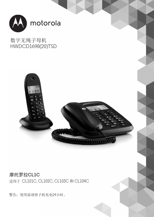
警告:使用前请将子机充电24小时。
D28C 系列适用于: D2811HC, D2811C, D2812C 和 D2813C数字无绳电话机带数字答录机HWDLCD1698(18)P/TSD欢迎您...使用您新购得的Motorola D28C数字无绳电话!• 电话主机可挂在墙上-所有子机请安置于收讯范围内。
• 1.6寸彩色显示屏。
• 可保存100组姓名号码的电话簿。
• 可与其它子机之间复制电话簿条目。
• 时钟屏保。
• 数字录音时间长达12分钟。
• 来电显示功能可显示来电者的身份,您也可在通话记录查看最近30个来电者的详细记录。
1• 一个主机可注册最多4个子机,每个子机可向最多4个不同主机注册。
• 可呼叫内线,转接外线呼叫,在两个内线及一个外线通话者之间进行三方通话。
请注意,本设备不适合在停电时用来拨打紧急电话。
您应备有其它的应急服务联系方式。
需要帮助吗?如果您在D28C的安装或使用上有任何问题,请拨打4008-838-698联系客服部门。
或者,您也可以参阅本手册“疑难解答”章节中的说明。
1您必须先向固话网络运营商申请开通来电显示或来电等待服务,方可享有这些功能。
您可能须支付开通费用。
此用户手册可为您提供一切所需的信息,帮助您充分利用本电话的功能。
要设置您的电话,请遵循后面几页“使用前的准备”中的简单指示。
重要信息仅使用自带的电话线。
下列配件齐全吗?• D28C主机和无绳子机• 2颗镍氢充电电池• 主机的电源适配器• 电话线• 说明书如果您购买的是D28C系列多子机配套,则还将获得以下的额外附件:• 系列子机及充电座• 2颗镍氢充电电池• 充电座的电源适配器1.使用前的准备 (8)2. 认识您的电话 (11)3. 电话功能操作 (18)3.1 启动/关闭子机 (18)3.2 呼叫 (18)3.2.1 拨打电话 (18)3.2.2 预先拨号 (18)3.2.3 结束通话 (18)3.2.4 接听来电 (18)3.3 调节听筒/话筒的音量 (18)3.4 静音模式 (18)3.5 内线通话 (19)3.5.1 呼叫另一个子机 (19)3.5.2 转接通话 (19)3.5.3 三方电话会议 (19)3.6 免提通话 (19)3.6.1 以免提方式拨打电话 (19)3.6.2 以免提方式接听来电 (20)3.7 重拨 (20)3.7.1 从重拨号码列表重拨一个号码 (20)3.7.2 将重拨号码列表中的号码保存至电话簿 (20)3.7.3 删除一个重拨号码/删除全部重拨号码 (20)3.8 锁定键盘 (20)3.9 寻呼/搜索子机 (20)4. 电话簿 (21)4.1 保存名字和电话号码 (21)4.2 在通话期间开启电话簿 (22)4.3 查看电话簿条目 (22)4.4 拨出电话簿条目的号码 (23)4.5 编辑名字和电话号码 (23)4.6 编辑铃声 (23)4.7 删除一个条目 (23)4.8 删除整个电话簿 (23)4.9 将一个条目复制至另一个子机 (24)4.10 将整个电话簿复制至另一个子机 (24)4.11 快速拨号键 (24)4.12 指定 / 清除快速拨号号码 (24)4.13 内存状态 (25)5. 子机设置 (26)5.1 子机铃声 (26)5.2 子机铃声音量 (26)5.3 听筒音量 (26)5.4 子机名称 (26)5.5 语言 (27)5.6 墙纸 (27)5.7 菜单颜色 (27)5.8 屏保 (27)5.9 省电等待时间 (28)5.10 屏幕对比度 (28)5.11 自动接听 (28)5.12 按键音 (29)5.13 PABX前导码 (29)6. 主机设置 (30)6.1 主机铃声 (30)6.2 主机铃声音量 (30)6.3 拨号模式 (30)6.4 响铃优先 (30)6.5 闪断模式 (31)6.6 第一声响铃 (31)6.7 系统PIN码 (31)6.8 恢复默认设置 (32)6.9 默认设置 (33)7. 时间和闹钟 (34)7.1 日期及时间 (34)7.2 设置闹钟 (34)7.3 启动/关闭闹钟 (34)7.4 关闭闹铃 (34)7.5 时间格式 (35)8. 议程提醒 (36)8.1 增加新议程 (36)8.2 关闭提醒铃音 (36)8.3 显示详情 (36)8.4 编辑议程 (37)8.5 删除议程 (37)8.6 删除所有议程 (37)9. 通话记录 (38)9.1 来电显示 (38)9.2 通话记录 (38)9.3 新来电提示 (38)9.4 查看新的未接来电 (38)9.5 从通话记录查看条目及拨号 (38)9.6 将通话记录的号码复制至电话簿 (39)9.7 删除一个条目 (39)9.8 删除全部记录 (39)10. 呼叫等待 (40)11. 宝宝监听 (41)11.1 启动宝宝监听 (41)11.2 改变宝宝监听灵敏度 (41)11.3 设置拨出号码 (41)12. 答录机 (43)12.1 主机控制键 (43)12.2 启动/关闭答录机 (43)12.3 答录延迟 (44)12.4 启动/关闭信息提示音 (44)12.5 屏幕提示 (44)12.6 录制自己的外出留言 (44)12.7 检查或删除您的外出留言 (45)12.8 选择外出留言模式 (46)12.9 录制备忘录 (46)12.10 来电监听 (46)12.11 播放留言 (47)12.12 删除全部旧留言 (47)12.13 启动或关闭遥控操作 (48)12.14 更改遥控操作的PIN码 (48)12.15 遥控启动您的答录机 (48)12.16 从另一个电话操作您的答录机 (49)13. 使用额外子机 (50)13.1 注册额外子机 (50)13.2 选择主机 (50)13.3 取消注册子机 (51)14. 疑难解答 (52)15. 相关信息 (54)1. 使用前的准备警告请勿将电话放置在浴室或其它潮湿之处。
设置地点您必须将D28C主机放在距离电源插座和电话端口2米以内的地方,缆线才能连接。
请确保主机距离其它电器设备至少1米以上,并且尽可能远离无线设备(例如无线宽带),以避免产生同类电波通讯干扰。
您的电话通过子机和主机之间传送无线信号的方式运作。
信号的强度取决于主机的位置。
请尽可能放在高处,以确保最佳收讯质量。
子机收讯范围D28C在户外可支持300米的传输范围(如果主机和子机之间无障碍物阻隔)。
主机和子机之间若有任何障碍物,将明显缩小收讯范围。
如果主机在室内,而子机在室内或户外,收讯范围一般最远可达50米。
厚墙会严重影响收讯范围。
信号强度子机上出现 图标,表示您正处于收讯范围之内。
超出主机范围时,屏幕上会显示Searching...(搜索中), 会不停闪烁。
通话期间,如果子机超出收讯范围,会发出超出范围的告警音。
如果在通话时您将子机移出收讯范围以外,线路将会断开。
移回收讯范围内,子机就会立即自动重新连接至主机。
装设重要事项主机必须保持接入电源插座。
在子机未充好电之前,请勿将电话线插入墙上的插座。
您只可使用产品配备的电源线和电话线。
应使用哪一个电源适配器?带有透明连接器的是连接主机的电源适配器;而带有红色连接器的是连接充电器的适配器。
连接主机1. 将带有透明连接器的电源适配器插入主机底部标明的端口,并将另一端插入墙上的电源插座,然后开启电源。
连接子机和充电器(只限于多子机配套)如果您购买的是多子机的配套产品,必须重复此步骤连接所有子机和充电器:1. 将带有红色连接器的电源适配器插入充电器底部标明 的端口。
2. 将本电话配备的2颗AAA 镍氢电池插入子机中。
然后将电池盖推回原来位置。
3. 将子机放在充电器上,第一次充电至少24小时。
当子机充电完成时,屏幕上会出现 图标,表示电池的电量已充满。
4. 充电24小时之后,将主机的电话线插入墙上的电话线插座。
重要事项警告!只能使用可充电式电池。
如果使用不可充电的电池,屏幕上将会显示WRONG BATTERY(电池不符)并停止充电。
请更换成可充电式电池。
低电量警告如果屏幕上显示 图标,表示您必须先为子机充电,才能再使用。
在充电期间,屏幕上的 图标会持续翻动。
电池效能在理想情况下,电池在每次充满电后可提供8小时的通话时间或100小时的待机时间。
请注意,新电池在正常使用几天之后才可达到最大效能。
为保持电池的最佳状态,每隔一段时间应关闭子机长达数小时。
每周至少一次将电池电量使用至耗尽为止,可有助维持电池的寿命。
可充电式电池的充电效能会随时间而递减,因此可提供子机的通话/待机时间也会越来越短。
最后就必须更换电池。
在子机第一次充电之后,接下来每天应充电约6-8小时。
电池和子机在充电期间可能会变热。
这是正常现象。
日期及时间如果已申请来电显示服务,当您接到第一通来电时,将会自动同步设置所有子机的日期和时间。
每当您收到一则答录机留言时会记录其日期和时间。
如果未申请来电显示服务,您可手动设置日期和时间。
手动设置日期和时间1. 按菜单,再按 u 或 d 滚动至时间和闹钟,然后按选择。
2. 日期 & 时间将会高亮显示。
按选择。
3. 输入年/月/日格式的日期,例如15 09 01 代表2015年9月1日,并输入12或24小时格式的时间。
按保存。
有关改变时间格式的方法,请参阅第34页。
4. 按n或返回直到您返回待机模式为止。
现在您的电话已完成设置,随时可以使用。
2. 认识您的电话子机概览A 听筒B 显示屏有关显示屏图标的简介,请参阅第13页。
C 重拨/上在待机模式下,按此键可开启Redial (重拨号码)列表并滚动浏览,请参阅第20页。
在通话模式中,按此键可调节音量。
在菜单模式中,按此键可在选项之间滚动。
在保存一个电话簿条目时,按住此键可输入暂停,请参阅第21页。
ABD EF H NM L KJ ID 选项键(左)按此键可开启菜单。
按此键可选择屏幕上显示的选项。
E 通话/免提听筒在待机模式下,按此键可拨出及接听来电,请参阅第18页。
在通话模式中,按此键可启动及关闭免提通话模式,请参阅第19页。
F *按住此键可在音频和脉冲拨号模式之间转换,请参阅第30页。
G Int(子机对讲)用于内线通话,请参阅第19页。
H 选项键(右)在待机模式下,按此键可开启电话簿菜单,请参阅21页。
按此键可选择屏幕上显示的选项。
I 导航键光环使用子机时会发光。
若闪烁则表示有新事件,例如未接来电。
J 结束通话/开关机按此键可结束通话,请参阅第18页。
在菜单模式中,按此键可返回待机屏幕。
在待机模式下,按住此键可关闭子机。
关闭子机后,按此键可重新开启子机。
K 电话簿/下在待机模式下,按此键可开启联系人列表并滚动浏览,请参阅第22页。