BTU使用说明书Word版
BTU操作规范

關机步驟---(二)
• 5 關閉爐子內部電源 • 6 關閉電源開關 • 7 關閉穩壓電源
注意事項---(一)
• 1 爐子加熱生產時,手.身體不要伸入爐中 • 2 爐子蓋子在平時生產時不能隨便打開 • 3 正常生產時,四個E- Stop不能隨便按下,要特別注意 • 4 機器出現異常情況,應立即通知工程帥處理
回焊爐BTU操作規范
開机步驟---(一)
• 1 打開穩壓器開關 • 2 打開回焊爐主電源開關 • 3 打開爐子內部電源UPS • 4 打開電腦 • 5 等待Wincon聯接 • 6 選擇所需程式投入生產
關机步驟---(一)
• 1 執行Cool down程序 • 2 等待約45分鍾,使爐內溫度均低於1000C • 3 執行Shut off程序 • 4 退出Wincon及Window
注意事項---(二)
• 5 生產線需要換線時若為最後一片, 爐前人員需將在此板子上空白處貼上防焊 標簽,並標明பைடு நூலகம்“最後一片”,爐後人員見 到板子上有此標示方可收線
爐前日常事務
• 保養表的填寫 • 正確認識N2流量,并如實填寫到N2流量表中
Panasonic TH-42BT300U TH-50BT300U 用户手册说明书

TQB2AA0629FCC STATEMENTThis equipment has been tested and found to comply with the limits for a Class B digital device, pursuant to Part 15 of the FCC Rules. These limits are designed to provide reasonable protection against harmful interference in a residential installation. This equipment generates, uses and can radiate radio frequency energy and, if not installed and used in accordance with the instructions, may cause harmful interference to radio communications. However, there is no guarantee that interference will not occur in a particular installation. If this equipment does cause harmful interference to radio or television reception, which can be determined by turning the equipment off and on, the user is encouraged to try to correct the interference by one or more of the following measures:• Reorient or relocate the receiving antenna.• Increase the separation between the equipment and receiver.• Connect the equipment into an outlet on a circuit different from that to which the receiver is connected.• Consult the dealer or an experienced technician for help.This device complies with Part15 of the FCC Rules. Operation is subject to the following two conditions:(1) This device may not cause harmful interference, and (2) this device must accept any interference received, including interference that may cause undesired operation.FCC CAUTION:To assure continued compliance, follow the attached installation instructions and use only shielded interface cables when connecting to computer or peripheral devices. Any changes or modifi cations not expressly approved by Panasonic Corp. of North America could void the user's authority to operate this device.FCC Declaration of ConformityModel No. TH-42BT300U, TH-50BT300UResponsible Party: Panasonic Corporation of North AmericaThree Panasonic Way 2F-5, Secaucus, NJ 07094Contact Source: Panasonic Solutions CompanyPanasonic Plasma Concierge 1-800-973-4390CANADIAN NOTICE:This Class B digital apparatus complies with Canadian ICES-003.Note:Do not allow a still picture to be displayed for an extended period, as this can cause a permanent image retention to remain on the Plasma Display.Examples of still pictures include logos, video games, computer images, teletext and images displayed in 4:3 mode. Trademark Credits• VGA is a trademark of International Business Machines Corporation.• Macintosh is a registered trademark of Apple Inc., USA.• SVGA, XGA, SXGA and UXGA are registered trademarks of the Video Electronics Standard Association.Even if no special notation has been made of company or product trademarks, these trademarks have been fully respected.• HDMI, the HDMI Logo, and High-Defi nition Multimedia Interface are trademarks or registered trademarks of HDMI Licensing LLC in the United States and other countries.4Specifi cationsTH-42BT300U TH-50BT300UPower Source 110 - 127 V AC, 50/60 HzPower ConsumptionRated Power Consumption330 W420 W Stand-by condition Save OFF 0.7 W, Save ON 0.4 W Save OFF 0.7 W, Save ON 0.4 W Power off condition0.2 W0.2 WPlasma Display panel Drive method : AC type 42-inch,16:9 aspect ratio Drive method : AC type 50-inch, 16:9 aspect ratioScreen size36.2” (921 mm) (W) × 20.4” (518 mm) (H)× 41.6” (1,057 mm) (diagonal)43.5” (1,105 mm) (W) × 24.4” (622 mm) (H)× 49.9” (1,268 mm) (diagonal)(No.of pixels)2,073,600 (1,920 (W) × 1,080 (H))[5,760 × 1,080 dots]Operating conditionTemperature32 °F - 104 °F (0 °C - 40 °C)Humidity20 % - 80 %Applicable signalsColor System NTSC, PAL, PAL60, SECAM, Modifi ed NTSCScanning format525 (480) / 60i · 60p, 625 (575) / 50i · 50p, 750 (720) / 60p · 50p, 1125 (1080) / 60i · 60p · 50i · 50p · 24p · 25p · 30p · 24sF, 1250 (1080) / 50iPC signals VGA, SVGA, XGA, SXGAUXGA ···· (compressed)Horizontal scanning frequency 15 - 110 kHzVertical scanning frequency 48 - 120 HzConnection terminalsLAN RJ45 10BASE-T/100BASE-TX, compatible with PJLink™AV IN VIDEOAUDIO L-R BNCRCA Pin jack × 21.0 Vp-p (75 Ω)0.5 VrmsHDMI TYPE A Connector COMPONENT/RGB INY/GP B/C B/B P R/C R/R AUDIO L-R BNCBNCBNCRCA Pin jack × 2with sync 1.0 Vp-p (75 Ω)0.7 Vp-p (75 Ω)0.7 Vp-p (75 Ω)0.5 VrmsDVI-D INAUDIO DVI-D 24 PinContent ProtectionStereo mini jack (M3) × 1Compliance with DVI Revision 1.0Compatible with HDCP 1.10.5 Vrms, Shared with PC INPC INAUDIO High-Density Mini D-sub 15 PinStereo mini jack (M3) × 1Y or G with sync 1.0 Vp-p (75 Ω)Y or G without sync 0.7 Vp-p (75 Ω)P B/C B/B: 0.7 Vp-p (75 Ω)P R/C R/R: 0.7 Vp-p (75 Ω)HD/VD: 1.0 - 5.0 Vp-p (high impedance)0.5 Vrms, Shared with DVI-D INSERIAL External Control TerminalD-sub 9 Pin RS-232C compatible 3D IR TRANSMITTER for 3D IR TRANSMITTER3D SHUTTER OUT DC 8V OUT M3 jack × 1Center plus, for EIAJ 4mm plugEXT SP Speaker Terminal 6 Ω, 16 W [8 W + 8 W] (10 % THD) Dimensions (W × H × D)40.2” (1,020 mm) × 24.1” (610 mm) × 3.5” (89 mm)47.7” (1,210 mm) × 28.5” (724 mm) × 3.5” (89 mm) Mass (weight)main unit only approx. 57.4 lbs approx. 75.0 lbswith speakers approx. 68.4 lbs approx. 86.0 lbsNote:Design and specifi cations are subject to change without notice. Mass and dimensions shown are approximate.Panasonic Solutions CompanyUnit of Panasonic Corporation of North America Executive Of fi ce :Three Panasonic Way 2F-5, Secaucus, NJ 07094Panasonic Canada Inc.5770 Ambler Drive Mississauga, Ontario L4W 2T3Customer’s RecordThe model number and serial number of this product can be found on its back cover. You should note this serial number in the space provided below and retain this book, plus your purchase receipt, as a permanent record of your purchase to aid in identi fi cation in the event of theft or loss, and for Warranty Service purposes.Model Number Serial Number© Panasonic Corporation 2011<Software Information for This Product>This product has software installed partially licensed under the Free BSD LICENSE.Free BSD LICENSE regulations under the above specifications are as follows:(These regulations are set by the third party; therefore the original (English) regulations are stated.)Copyright © 1980, 1986, 1993The Regents of the University of California. All rights reserved.Redistribution and use in source and binary forms, with or without modification, are permitted provided that the following conditions are met:1. R edistributions of source code must retain the above copyright notice, this list of conditions and the following disclaimer.2. R edistributions in binary form must reproduce the above copyright notice, this list of conditions and the following disclaimer in the documentation and/or other materials provided with the distribution.3. A ll advertising materials mentioning features or use of this software must display the following acknowledgement:This product includes software developed by the University of California, Berkeley and its contributors.4. N either the name of the University nor the names of its contributors may be used to endorse or promote products derived from this software without specific prior written permission.THIS SOFTWARE IS PROVIDED BY THE REGENTS AND CONTRIBUTORS “AS IS” AND ANY EXPRESS OR IMPLIED WARRANTIES, INCLUDING, BUT NOT LIMITED TO, THE IMPLIED WARRANTIES OFMERCHANTABILITY AND FITNESS FOR A PARTICULAR PURPOSE ARE DISCLAIMED. IN NO EVENT SHALL THE REGENTS OR CONTRIBUTORS BE LIABLE FOR ANY DIRECT, INDIRECT, INCIDENTAL, SPECIAL, EXEMPLARY , OR CONSEQUENTIAL DAMAGES (INCLUDING, BUT NOT LIMITED TO, PROCUREMENT OF SUBSTITUTE GOODS OR SERVICES; LOSS OF USE, DATA, OR PROFITS; OR BUSINESS INTERRUPTION) HOWEVER CAUSED AND ON ANY THEORY OF LIABILITY , WHETHER IN CONTRACT, STRICT LIABILITY , OR TORT (INCLUDING NEGLIGENCE OR OTHERWISE) ARISING IN ANY WAY OUT OF THE USE OF THIS SOFTWARE, EVEN IF ADVISED OF THE POSSIBILITY OF SUCH DAMAGE.USA Only:Disposal may be regulated in your community due to environmental considerations. For disposal or recycling information, please visit Panasonic website:/environmental or call 1-888-769-0149.Printed in U.S.A.。
BTU回流焊操作指示((BTU P150) (A-0352)
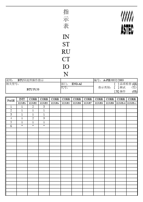
指示表一. 版本二. 目录三.四.五 BTU回流焊操作指示一.作业前准备工作.1.准备机器所需的指示及记录表格.2.准备ESD工具.二.作业内容.(1).开机步骤1.打开机身后面旋转开关到ON 位置.2.拉起所有的紧急掣.3.在机身前面操作面板上向右扳动INSTRUMENT POWER,再按MASTER START 按钮.4.打开电脑主机的电源开关.a).OPERATOR (NAME)直接输入(不需密码) b).6324 (NAME) 再键入 6324 (PASSWORD) 图标. 8.选择EES (.rep)文件,点OPEN. 9.再点击 RUN, 选择 YES 确认.10.机器自动启动升温,点STATUS 点PROCESS MONITOR GRAPHIC 或点击图标.11.当温度达到指定设定值后.机器亮绿灯.12.开始过板.(2).机器出现警报.1.红色警报(红灯亮,机身前面操作面板 RESET 灯亮)a.当出现红色Alarms警报及示警画面.b.点击Acknowledge 确认.c.出现Operator sign on 窗口,输入 operator 或 6324 (要password).d.在Alarms status 窗口中,点击Clear Alarms 及在机身前面的操作面板按 RESET键(灯灭),排除后点 Close 退出.e.机器正常后,绿灯亮,屏幕在左上角状态栏出现绿色 Ready.2.黄色警报(黄灯亮,机身前面操作面板RESET 灯亮)a.排除方法同上.3.需打开机盖操作时(如塞板).b.机器会发出警报声,机盖会慢慢打开.c.完成后,恢复同样扳动d.机器会发出警报声,机盖会慢慢关闭.4.关机步骤.a.在Recipe 菜单选择Open Recipe 或在工具列点击图标选择 Shutdown, 点 open. c.在操作面板按Master Stop 键, 电脑退出BTU 系统.d.再按紧急掣,关闭电脑电源.e.旋转关闭总电源开关.5.回流温度设置如下.三.注意事项:1.检查导轨是否与当前底板相符,如有不符通知工程人员调较,不可自行调整。
BTU操作注意事项
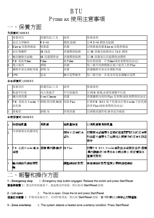
BTUPyramax使用注意事項一、保養方面月保養或300HRS保養項目清潔用品/工具說明保養說明1 前后方型軸杆WD-40 潤滑,除銹以WD-40潤滑及除銹2 Blower及散熱風扇吸塵器清潔以吸塵器清潔Blower及散熱風扇3 前后導螺桿3B.T&D 清潔潤滑除銹以3B清潔及除銹並以T&D潤滑4 輸送鏈條及齒輪3B.高溫潤滑油清潔潤滑除銹以3B清潔並以高溫潤滑油潤滑5 F/M系統Filter Filter 換Filter 每星期更換一片Filter(或依實際情況而定)6 進口氣帘酒精清潔每三個月用酒精擦去進口氣帘上的Flux7 爐膛外部及選配周邊酒精.布清潔清潔爐膛外部及各選配周邊8 UPS 電表輸出電壓檢查每三個月放一次電及用電表測輸出電壓半年保養或1800HRS保養項目清潔用品/工具說明保養說明1 軌道平行度內六角扳手平行度檢查以PCB實測,必要時調整平行度2 爐內部清潔Oven Cleaner 清潔清潔爐膛內部的Flux及異物(或依實際情況而定)3 F/M系統及Cooler下區托盤酒精/異丙醇/鹼液清除Flux 打開F/M BOX取下托盤及打開Cooler下區托盤清理Flux(或依實際情況而定)4 排風管酒精,布管壁清潔以酒精清潔管壁,檢查是否破損年度保養或3600HRS1 機器抽風量測風儀抽風量檢查以測風儀實測排風量2冷卻循環水的潔凈度排除不潔凈的冷卻水打開裝冷卻循環水容器的底部閥門依水的潔凈度放出部分循環水之后再加上同樣多的潔淨水到容器中3 F/M系統/Cooler區冷凝器酒精/異丙醇/鹼液除Flux 打開F/M BOX//Cooler區取出冷凝器在溶液(酒精/異丙醇鹼液/)中浸泡半小時後裝上(或依實際生產情況而定)4 輸送鏈條及鏈條張緊輪調整鏈條的鬆緊檢查鏈條的鬆緊程度必要時縮短鏈條二、報警和操作方面1、Emergency stop| : Emergency stop button engaged. Release the switch and press Start/Reset紧急停报警| :紧急停按钮被按下。
BTU使用说明书.
目录注意事项 (1)服务与保证 (3)一、概述 (4)二、工作原理 (5)三、主要技术性能及参数 (6)四、仪器的面板结构 (7)五、仪器的安装 (8)六、仪器的使用 (16)七、仪器的停机与存放 (16)附:仪器的校准记录 (17)注意事项!电源注意事项●仪器使用220VAC±10%、50/60Hz、3A电源,要求接地良好,不应有高频或强磁场干扰。
我公司建议用户给仪器配备有净化功能的交流稳压器或UPS电源,以确保仪器在长期的使用中有稳定的电源供给。
同时有助于延长仪器的使用寿命。
!配管注意事项●取样管必须是材质致密、内壁光滑清洁、无砂眼的管道,且越短越好。
我公司推荐用户使用φ6的不锈钢管、厚壁且内径小的聚四氟乙烯管、紫铜管或厚壁(1mm以上)聚乙烯管等。
不得采用弹性高、渗透性强的塑料管及各种橡胶管。
!安装注意事项●仪器应该现场安装,并且与取样点要尽可能的接近(≤2米)。
●当被测气体压力高于0.1MPa时,应在取样点处安装可靠的减压阀。
若仪器内的样气压力高于5 KPa时,传感器将可能破裂!●取样系统管路中的接头应尽可能的少,接头处密封性要好,不得采用套接的方法。
●必须保证仪器的出口排气通畅。
仪器排放的气体应用管道引到室外排空。
!使用及保存注意事项●仪器在使用过程中不可打开外壳,避免发生烫伤及触电危险。
●仪器在使用、存放、及运输过程中应避免强烈震动,以免损坏氧化锆传感器。
●仪器在存放期间应保持清洁,要防止仪器受潮,进排气嘴应加盖防尘帽,以防落入异物及灰尘。
!被测量气体注意事项●测试气体中的腐蚀性气体(二氧化硫、硫化氢、氯化氢、氯、氟化氢、氟等)或毒性气体(矽、铅、磷、锌、锡、砷等)可能会造成传感器的损坏,应选用适当的过滤器滤除这些气体和物质。
●样气中如有H2、CO、CH4等还原性(即可燃性)气体,不但对测量结果产生影响,而且含量较大时有可能引起爆炸,所以应该从样气中滤除这些气体。
被测样气中氧含量小于10PPm时,还原性气体的含量应小于1 PPm,被测样气中氧含量大于10PPm时,还原性气体的含量应小于2~4 PPm;请严格遵守以上所列注意事项,否则将造成人为测量误差或重大事故!!!服务与保证仪器自出厂之日起,仪器的保修期限为一年。
Tennant Ultrasonic BTU流量计说明书

The Series TUF Tennant Ultrasonic BTU Flowmeter is a MID/EN1434 approved highly accurate and stable energy meter. It utilizes ultrasonic technology to measure heating and cooling energy consumption. The Series TUF incorporates a flowmeter, temperature meter, and a calculator into a single, compact unit. The size and lack of moving parts means the Series TUF requires minimal maintenance. The 8-digit LED display enables easy reading of the meter’s recorded values; including temperature, flow-rate, energy consumption, etc. These features make it ideal for installation on chillers, boilers, and individual apartment piping. With the optional couplings it is capable of being used with either NPT or BSPT pipe sizes. It is the perfect meter for tenant billing applications.FEATURES• Lower maintenance costs with local parameter display and no moving parts • Serial communication output allows for easy transfer of data• Flow and temperature monitor in one unit eliminates the need for multiple unitsINSTALLATION NOTES1. Avoid tugging on the temperature probe’s cables.2. Ensure the water is flowing in the direction indicated by the arrow on the meter’s body.3. If several meters are installed on the same vertical pipe work, each meter should be separated from the others to avoid pipe leakage or fallen debris that could affect the other meters’ operation.INSTALLATION INSTRUCTIONS1. Install the meter as shown in either Figure 1 or Figure2.2. Mount the temperature sensor with the blue tag on the corresponding return pipe on application. The sensor with the red tag has already been installed in the meter.3. Flush the system in the proper direction until: • No impurities remain in the filter and pipe.• No water leaks when pressure is added to the system.• The humidity inside the enclosure containing the meter does not exceed 93%.4. After flushing for a period of time; close the ball valves on either side of the meter and flush the impurities out of all filters.*3.6 V ER26500 battery may be purchased separately to power display only.1. Ensure that there is a 10 diameter straight run of pipe upstream and a 5 diameter straight run of pipe downstream form the meter.2. See the installation positions in Figure 3, in which A and B are the proper installation positions, while C and D are the improper positions.3. If the meter is installed on the horizontal pipe, it must be oriented at least 45° fromhorizontal (see Figure 4). If the meter’s face is horizontal, then debris accumulationcan increase inaccuracies (see Figure 5 for correct and incorrect orientations). There is no special requirement when installing on the vertical pipe work.4. Handle display with care. LCD display may damage with force.Note: the meter can be installed on the return pipe or the supply pipe according to user’s needs, but it should be selected in advance.If the following requirements are not followed, then large air particles and impurities in the pipe could influence the meter’s measuring accuracy.Do not install the meter near a high temperature heat source such as during electro gas welding. Doing so after installing an optional battery could cause the battery to explode and causeinjury to people and damage the meter.Do not directly weld the meter on to the pipe; the extreme heat will damage the BTU meter’s internal elements.If not specified at time of order, refer to appendix III to change from supply to return programming.Change from supply to return, and vice-versa, is only possibleusing digital communication protocols.DFigure 2: Installation diagram for TUF-500 to TUF-2000Figure 3: Installation positions Figure 4: Mounting rotation1. If meter is not in use during freezing conditions, drain all water from the connecting pipe. Low temperatures will cause the water to freeze in the pipe and damage the meter.2. This device is intended to be used with clean water. While dirty water will not damage the meter, it will cause errors in the reading.3. A filter should be mounted near the meter and cleaned regularly.4. If the heat exchanging system is operating normally, but the instantaneous flow- rate of the heat meter reduces significantly, then there is too much dirt in the filter. This will narrow the pipe and reduce the flow. Cleaning the filter will fix the problem.5. To protect the meter and avoid damage from harsh conditions, it is recommended that the meter be encased in an enclosure.6. Primary Address: first 2 digits of Manufacturer ID7. Secondary Address: later 8 digits of Manufacturer ID8. Company Code: BAS (08 33)• Version: 541. section.2. Display UnitsEnergy is displayed in kW•h, power is displayed in kW, flow volume is displayed as m 3, and flow-rate is displayed in m 3/h.3. Display Detailsa. “Monthly Reading Date” is displayed as “Pd= XX”, in which XX is the end date of the current month’s energy summation. The factory default value is 31, meaning that the monthly recording period ends at midnight on the 31st day of the month. At this time the current month’s cumulated energy will be stored and the system will begin to record the next month’s energy.b. The meter can store and display the recordings from the past 18 months.c. The units for “Sum of Working Time” (hours) is displayed as h.d. “Software and Protocol Editions” are displayed as “UEr.X.X X.X”. The first X.X is the software edition code and the second X.X is the communication protocol edition code.e. “Leaving-factory serial number” is the meter’s identification number, which is the same as the one in the external label. This serial number is a unique number set by the factory; it is also the secondary address in M-BUS system.f. Battery Voltage displays “UCC=X.XX” (the default unit is Volts). When the battery’s voltage capacity is lower than 2.9±0.1 V, “ ” will appear on the display. This symbol will not appear if no battery is installed.g. If there are any unresolved errors, the start date will display as normal but the end date will display “00-00-00”, and then the error message will be displayed.4. LCD Display Data: • Cooling energy • Heat energy • Volume• Operating time • Flow temperature • Return temperature • Temperature difference • Power• Volume flow • Recorded date • Recorded energy • Recorded volume*Battery not includedCOD=XXXX Low Battery*©Copyright 2021 Dwyer Instruments, Inc.Printed in U.S.A. 1/21FR# 444246-50 Rev. 54. Display MenusWARRANTY/RETURNRefer to “Terms and Conditions of Sale” in our catalog and on our website. Contact customer service to receive a Return Goods Authorization number before shipping the product back for repair. Be sure to include a brief description of the problem plus any additional application notes.Modbus ® is a registered trademark of Schneider Automation, Inc.。
2 BTU回焊炉作业指导书
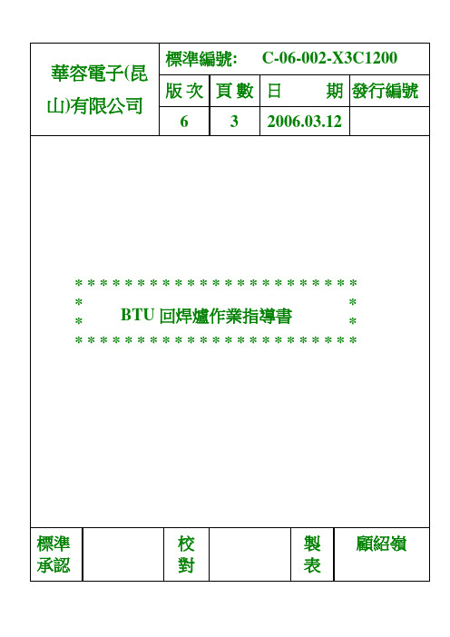
版次
6
標準編號 C-06-002-X3C1200 製表 日期 2006.03.12
製 顧紹嶺 表
華 容 電 子 (昆 山 )有 限 公 司
文件名稱 BTU 回焊爐作業指導書
d. 電器控制部位. 檢查電力線及其接電后是否有過熱或接觸不良. 6-3. 每日白班 8:00 至 9:00 操機員按日點檢表進行保養. 6-4:開關機程序. a.開機 (1).檢查機器前后方四個紅色緊急按鈕是否有彈起; (2).打開機器總電源開關,UPS ON (3).電腦自動進入 REFLOW 軟體,打開 RECIPE 菜單選擇要運行的爐溫設 置程式, 提示你輸入用戶名和密碼 , 用戶名輸入 BTU 確定,完成開 機程序. b.關機 (1).關機前先檢查爐內是中還有 PCB; (2).運行 SHOWDOWN 菜單,,每個溫區溫度低于 300C 之后會自動關閉 REFLOW 軟體和電腦; (3).關閉 UPS,關閉機器總電源; 6-5. 程式的編寫 a. 輸入程式機種之溫度軌道速度和寬度的設定 b. 確認各區溫度是否與和軌道速度是否與 PROFILE 設定相符; c. 檢查軌道寬度是否適合基板順暢流入; d. 一切設定好之后,可以選擇 Recipe 菜單中的 Save As 存取你爐溫設置 的名稱; e. 首件確認焊接狀況是否良好. 6-6. 作業中的注意事項 a.確認各溫區誤差范圍為正負 3 度. b. 相鄰兩片 PCB 頇保持 10CM 以上距離. c. 有 AI 件或 PCB 易彎曲時采用墊基板,打開中間支撐 PIN 以輸送帶傳 送方式完成回流焊. d. 出現錫膏未熔化,PCB 烤黃等現象時要及時通知技朮人員處理. e.不可直接把 PCB 推入軌道,必頇放于過橋,使 PCB 自動流入 f. 生產中若需要對溫度,軌道速度進行調整,可直接在生產界面進行設 定,再運行即可, 調可使用爐子的 Edge Rail Adjust 這個旋鈕進行調 適用 標準 承認 全公司 頁次 校 對
BTU说明书
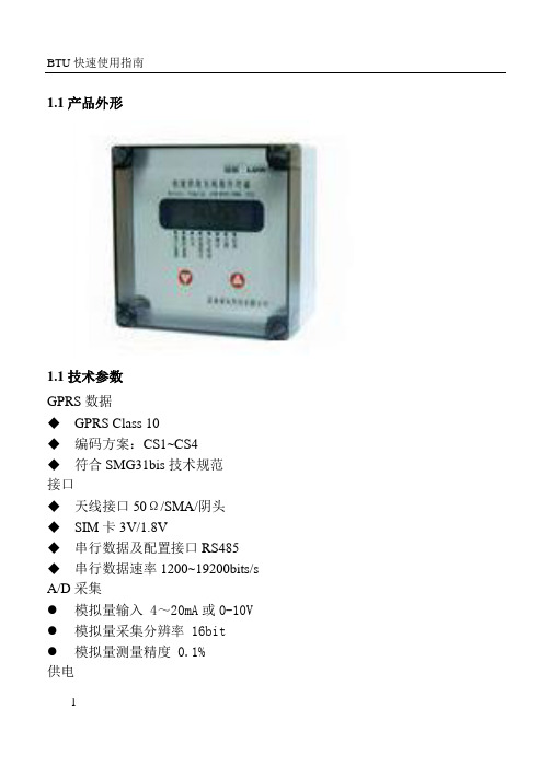
1.1产品外形1.1技术参数GPRS数据◆GPRS Class 10◆编码方案:CS1~CS4◆符合SMG31bis技术规范接口◆天线接口50Ω/SMA/阴头◆SIM卡3V/1.8V◆串行数据及配置接口RS485◆串行数据速率1200~19200bits/s A/D采集●模拟量输入 4~20mA或0-10V ●模拟量采集分辨率 16bit●模拟量测量精度 0.1%供电121 23 45 6 7 8◆电压+7 ~+9VDC,7.2V能量型电池功耗(外供电压值:7.2V)◆休眠电流<50uA◆数传电流<200mA其他参数◆尺寸130*130*85 (不包括天线)◆重量约230g◆工作环境温度-30~+70ºC◆储存温度-40~+85ºC◆相对湿度95%(无凝结)◆防水等级:IP661.2端子定义1.3 指示灯说明LED1LED2 LED3LED1:为数据灯,当设备收发数据时此等亮,电路板上标识为DLED2:为网络连接指示灯,当设备连接到网络后此灯亮,电路板上标识为L 34LED3:为GPRS 指示灯,当设备连网过程中此灯亮,电路板上标识为G 1.4 设备供电及参数设置 1.4.1 设备连接BTU 接线端子 485/232转换器1.4.2进行参数设置● 按照上图连接设备与计算机● 打开RTU 设置软件8.7,按照左侧的参数设置说明填写参数项,然后点查找设备按钮● 按参数设置按钮S2,此时设备液晶屏显示进入倒计时状态,设置软件提示已找到设备● 点对应项的“写参数”按钮,界面变为黄色时,表示参数已经写入成功 ● 参数设置完成后,按参数设置按键,设备退出倒计时状态,返回正常的工作模式。
5置,请查看设备是否仍在倒计时状态,否则需要重新进入。
1.5 设备各项功能的使用方法 1.5.1 定时定点上报数据在采集通道设置里设置上报起始时间、上报周期和采样周期(最小单位为分钟),采样周期指模拟量采集部分的数据采集间隔,数据采集上来后暂存在设备存储器内,到上报时刻时才把数据上报到中心,所以为节约电量,可将上报周期设置的稍长些。
- 1、下载文档前请自行甄别文档内容的完整性,平台不提供额外的编辑、内容补充、找答案等附加服务。
- 2、"仅部分预览"的文档,不可在线预览部分如存在完整性等问题,可反馈申请退款(可完整预览的文档不适用该条件!)。
- 3、如文档侵犯您的权益,请联系客服反馈,我们会尽快为您处理(人工客服工作时间:9:00-18:30)。
目录注意事项 (1)服务与保证 (3)一、概述 (4)二、工作原理 (5)三、主要技术性能及参数 (6)四、仪器的面板结构 (7)五、仪器的安装 (8)六、仪器的使用 (16)七、仪器的停机与存放 (16)附:仪器的校准记录 (17)注意事项!电源注意事项●仪器使用220VAC±10%、50/60Hz、3A电源,要求接地良好,不应有高频或强磁场干扰。
我公司建议用户给仪器配备有净化功能的交流稳压器或UPS电源,以确保仪器在长期的使用中有稳定的电源供给。
同时有助于延长仪器的使用寿命。
!配管注意事项●取样管必须是材质致密、内壁光滑清洁、无砂眼的管道,且越短越好。
我公司推荐用户使用φ6的不锈钢管、厚壁且内径小的聚四氟乙烯管、紫铜管或厚壁(1mm以上)聚乙烯管等。
不得采用弹性高、渗透性强的塑料管及各种橡胶管。
!安装注意事项●仪器应该现场安装,并且与取样点要尽可能的接近(≤2米)。
●当被测气体压力高于0.1MPa时,应在取样点处安装可靠的减压阀。
若仪器内的样气压力高于5 KPa时,传感器将可能破裂!●取样系统管路中的接头应尽可能的少,接头处密封性要好,不得采用套接的方法。
●必须保证仪器的出口排气通畅。
仪器排放的气体应用管道引到室外排空。
!使用及保存注意事项●仪器在使用过程中不可打开外壳,避免发生烫伤及触电危险。
●仪器在使用、存放、及运输过程中应避免强烈震动,以免损坏氧化锆传感器。
●仪器在存放期间应保持清洁,要防止仪器受潮,进排气嘴应加盖防尘帽,以防落入异物及灰尘。
!被测量气体注意事项●测试气体中的腐蚀性气体(二氧化硫、硫化氢、氯化氢、氯、氟化氢、氟等)或毒性气体(矽、铅、磷、锌、锡、砷等)可能会造成传感器的损坏,应选用适当的过滤器滤除这些气体和物质。
●样气中如有H2、CO、CH4等还原性(即可燃性)气体,不但对测量结果产生影响,而且含量较大时有可能引起爆炸,所以应该从样气中滤除这些气体。
被测样气中氧含量小于10PPm时,还原性气体的含量应小于1 PPm,被测样气中氧含量大于10PPm时,还原性气体的含量应小于2~4 PPm;请严格遵守以上所列注意事项,否则将造成人为测量误差或重大事故!!!服务与保证仪器自出厂之日起,仪器的保修期限为一年。
凡在此期限内,工作人员在正常操作的情况下,仪器出现的软件或硬件的故障,我公司均负责免费维修及更换零部件。
若由于工作人员违反操作规程、不严格按照使用说明操作仪器以及由于不可抗拒的因素而对仪器造成的损坏,我公司不负责免费维修。
如需维修,我公司将根据损坏情况适当收取维修成本费用。
如有用户需要,我公司也可指派技术人员进行现场培训。
如果您对本公司的仪器在使用和操作过程中,还有什么疑问及要求请及时与我们联系,以便我们能给您提供更完善的服务。
联系方式见封底。
一、概述该氧分析仪是利用氧化锆氧浓度差电池作为检测传感器的氧量分析仪器。
该仪器测控系统采用了最新型的单片机计算与控制系统,USB与上位机通讯显示及控制、新型稳流气路系统;具有精度高、响应快、性能稳定、功能齐全、操作方便、气体分析过程连续等优点。
该仪器适用于制气、化工、冶金、电子工业、回流焊、医疗等方面的气体中氧含量的检测。
本仪器具有以下特点:●一体化设计,体积小、重量轻、结构简单、布局合理;●纯度、炉温、热电偶温度、锆管电势等参数均可显示,便于参考;●标准电流输出(电压输出)、比例阀调节输出、纯度越限报警、纯度越限开关量输出等各项参数均可通过按键进行设置和修改;●传感器炉温的测量与控制均由单片机完成,并具有超温自动切断加热电源的功能,安全可靠;●仪器分析过程连续,量程自动切换,可用于在线分析或实验室分析等;●直观的上位机通讯程序,可实时显示氧纯度、炉温、仪器运行时间、输出电流、比例阀开度等,方便的PID调节功能,可根据客户的需求,设定需要的氧含量;●多通道可定时自动检测功能,通过上位机控制检验通道并实时检测不同通道氧含量。
二、工作原理仪器的工作原理如图1.0所示。
它主要由气路系统、氧化锆传感器、微机测控系统三部分组成。
2.1气路系统气路系统是用来给氧化锆传感器提供一个稳定流量的纯净样气的系统,样气由进气嘴通入(之前需经过净化处理),经过流量计后,进入传感器(使传感器产生与氧含量相关的电信号),再经过稳流装置后经排气嘴排出。
(压力为负压时需增加气泵增压) 2.2氧化锆传感器氧化锆传感器是由氧化锆陶瓷材料制成的氧浓度差电池,在高温时氧化锆具有氧离子的传导特性,当氧化锆管的两个电极之间的氧分压不同时,氧浓度差电池产生一个与氧浓度成比例的电势,电势大小按下式计算:E = lnRT 4FP 0 P式中:R ——理想气体常数F ——法拉第常数T ——氧化锆加热炉绝对温度(K)P0 ——空气中氧分压(20.6%)P ——样气中的氧分压通过测量氧浓度差电池的电动势E与温度T,就可以计算出样气中的氧分压,即氧含量。
浓度差电池的各种干扰电势,如本底电势、渗透效应、气流冷却效应等,通过硬件和软件的特殊设计进行修正。
2.3微机测控系统微机测控系统以单片机为核心,外围信号变换及放大电路、模拟开关、温控电路、显示器、PID控制调节输出、标准电流、电压输出,过温保护电路等组成,用来对测试结果进行计算、修正、控制和信号输出。
三、主要技术性能及参数3.1测量范围:0.01PPmO2~25%O2;3.2精度:≤±5%FS(0.01~10PPmO2);≤±2%FS(10PPmO2以上);3.3稳定性:零点漂移≤±2%F S /7d ;量程漂移≤±2%FS/7d;3.4 重复性: ≤1%;3.5工作炉温:750℃;3.6预热时间:<15min;3.7响应时间:<30s;3.8样气流量:400ml/min(流量计上的刻度处);3.9样气压力:≤0.1Mpa3.10工作环境:温度:-30~+50℃;相对湿度:<95%;3.11输出信号:PID控制4~20mA或标准4~10mA(0-10V)信号;3.12报警功能:氧含量越限报警及温控失灵报警;3.13触点输出:上下限触点输出对应的氧含量可任意设置;3.14触点容量:~220V 1A;24VDC 2A;3.15电源电压:220VAC±10%,50/60Hz,3A;3.16外型尺寸:229(宽)×178(高)×374mm(深);3.17重量:3.8kg。
四、仪器的面板结构仪器的前、后面板分别如图1.1、图1.2所示。
前面板电源开关和流量计组成;流量计可以根据实际需要调节流过传感器的样气流量;后面板自左向右依次由排气口、(I、II、III三路)进气口、排风扇、RS-485、电流和控制输出接线端子和交流电源插座组成。
RS-485通过485转USB输出端子连接至PC机;后排接线端子输出的信号,可以远传至控制室或控制其他设备的动作;排风扇则可以为整机起到降温的效果。
图1.1 仪器的前面板图1.2 仪器的后面板五、仪器的安装5.1仪器安装前的检查仪器由运输或存放状态转入使用前,应做如下检查:(1)附件及外观检查检查电源电缆、通讯电缆、安装软件、使用说明书、等附件是否齐全及完好;仪器外观不应该有划伤、变形现象,无异常现象后方可通电检查。
(2)仪器通电后的检查首先将安装软件装入电脑,接入数据通讯线,仪器通电后,打开O2 Controlor软件,设置好通讯端口,软件下方temperature:窗口的温度应不断增加,当数字增加到750温定后,仪器方可正常测量。
接入24V气泵控制电源,能听到气泵轻微的嗡嗡声。
用流量调节阀可使流量在零到最大范围内任意调节。
符合以上现象后方可继续下面的安装和使用。
如果仪器有缺损或通电后显示异常请不要使用,应立即与我公司售后服务部联系,以便妥善处理,避免仪器严重损坏或事故发生!5.2仪器的安装仪器的安装必须按下述要求进行,否则将无法保证仪器正常使用。
5.2.1电源的连接仪器使用220VAC±10%、50HZ/60HZ,3A电源,要求接地良好,不应有高频或强磁场干扰。
建议用户给仪器配备有净化功能的交流稳压器或UPS 电源,以确保仪器在长期的使用中有稳定的电源供给。
5.2.2通讯电缆的连接本仪器提供串行异步半双工RS485 通讯接口,采用MODBUS-RTU 协议,通讯线缆经过485转USB直接与PC相连。
USB的一端直接插入电脑,另一端与仪器后面板DB9针连接。
5.2.3 通讯USB-485驱动的安装打开仪器提供的光盘,找到UT850文件夹,根据所使用的操作系统选择相应的驱动,如以XP为例选择,运行程序,进行驱动的安装,安装完成后插入USB-485设备,进入电脑设备管理器端口(COM和LPT)项,记录此时的串口端口,此处为COM2(不同电脑此项端口号不同)5.2.4软件操作5.2.4.1运行软件主界面区由三部分组成:菜单设置区、实时数据显示区、历史数据设置和数据曲线记录区。
⏹菜单设置区:◆Language语言选择:可实现软件的中英文切换;◆Option功能设置:可进行仪器各项参数的设置;◆About关于软件;主要说明一下Option功能设置项:点击Option出现四级设置菜单:A、Comm Setting:通讯端口设置菜单设置Port:USB通讯端口设置项:选择端口号,参照5.2.3;Bauding:波特率设置:设置为9600;DataBit:数据位数:设置为8位;StopBit:停止位:设置为1位;Parity:奇偶检验位:设置为无校验;打开仪器电源,然后进行以上端口设置,点击Connect按钮,进行仪器通讯连接。
连接后软件左下角出现标志,代表连接成功,反之显示连接失败。
B、PID Parameter:PID参数设置项单击PID Parameter项出现密码对话框输入密码:输入“2222”后进入PID 设置项。
O2 Setpoint:需要设定的目标氧含量;Offset:相对于目标氧含量进行的正负偏移量调节;PID P Parm(P):比例控制。
输出与输入误差信号成比例关系,比例控制能迅速反应误差,从而减小稳态误差。
PID I Parm(I): 控制器的输出与输入误差信号的积分成正比关系。
积分项对误差取决于时间的积分,随着时间的增加,积分项会增大。
这样,即便误差很小,积分项也会随着时间的增加而加大,它推动控制器的输出增大使稳态误差进一步减小,直到等于零。
因此,比例+积分(PI)控制器,可以使系统在进入稳态后无稳态误差。
PID D Parm(D):控制器的输出与输入误差信号的微分(即误差的变化率)成正比关系。
它能预测误差变化的趋势,这样,具有比例+微分的控制器,就能够提前使抑制误差的控制作用等于零,甚至为负值,从而避免了被控量的严重超调。