横河温度变送器选型手册GS01C50B01-00E_013
横河GS-ISC450G_C
[类型:S2]
说明 感应式电导率转换器 AC(100…0VAC)供电 DC(1…VDC)供电 通用型 FM型 通用安装工具包(盘 装,管装,壁装) 管装和壁装硬件(*) 盘装硬件(*) 遮盖罩(不锈钢)(*) G1/ (*) 1/NPT (*) M0 (*) 不锈钢铭牌(*1)
L.机壳:
E.接点输出
M.电源
控制功能:
保持: 安全故障:
(*)说明:当接点输出电流大于A时,环境温度应低于 0 C。
ISC0G-A: 额定值; 100-0V AC 可接受的电压范围;0~V AC 额定值; 0/0Hz 可接受的频率范围; 0Hz±%,0Hz±% 功耗; 1伏安 ISC0G-D: 额定值; 1-V DC 可接受的电压范围;10.8~.V DC 电量; 10瓦特 EN 1010-1 CSA C. No.1010-1 UL 1010-1 FM11 Class I,Div.,Group ABCD,T用于Ta -0~ºC EMC: 符合EN1 Class A,AS/NZS CIPR 11 安装高度: ≤千米 符合IEC 1010: II分类(注) 符合IEC 1010: 污染等级(注) 安全认证:
General Specifications
GS 12D06D05-01C-C
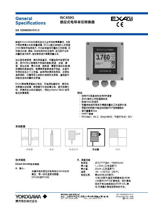
ISC450G 感应式电导率仪转换器
新型EXAxt 0系列满足当今工业市场的最高需求。 为用 户带来更高水平的质量保障。 EXAxt通过独特的人机界面 (HMI)帮助并指导用户, 不仅能够呈现可靠的工艺数据, 还 可通过诊断、 趋势、 日志和按步校正程序, 成为用户分析 测量的有力助手, 有效帮助用户提高质量水平。 该仪表安装简便,操作界面直观,无需指导手册便可使 用。其HMI可以根据用户选择的语言(英语、法语、德 语、西班牙语、意大利语、瑞典语、葡萄牙语和日语)提 供清晰的菜单结构。触摸屏界面具有显示性能。主显示 可同时给出三个工艺值。能够同时提供电导率、浓度和 温度读数。内置预定义参数补偿矩阵浓度表,直接显示 和输出在线测量的浓度值。 EXAxt具有高度智能化特点,可连续检查软件、硬件和 传感器系统故障。转换器不仅将故障分类、显示故障代 码,并提供充分的处理指引,同时以Namur NE 规范 输出故障信息。
Yokogawa 温度传感器连接头转发器说明书
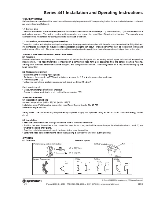
Series 441 Installation and Operating Instructions 1 SAFETY NOTESSafe and secure operation of the head transmitter can only be guaranteed if the operating instructions and all safety notes contained are understood and followed.1.1 Correct UseThe unit is a universal, presettable temperature transmitter for resistance thermometer (RTD), thermocouple (TC) as well as resistance and voltage sensors. The unit is constructed for mounting in a connection head (form B) and a field housing. The manufacturer cannot be held responsible for damage caused by misuse of the unit.1.2 Installation, commissioning and operationThe unit is constructed using the most up-to-date production equipment and complies with the safety requirements of the EU guidelines. If it is installed incorrectly or misused certain application dangers can occur. Trained personnel must do installation, wiring and maintenance of the unit. These personnel must have read and understood these instructions and must follow them to the letter.2 FUNCTION AND SYSTEM CONSTRUCTION2.1 FunctionProvides electronic monitoring and transformation of various input signals into an analog output signal in industrial temperature measurement. The head transmitter is mounted in a connection head form B or separated from the sensor in a field housing. Setting up of the head transmitter is done using PC and configuration software. The configuration kit is required for setting up the head transmitter.2.2 Measurement systemTransforming the following input signals:• Resistance thermometers (RTD) and resistance sensors (in 2, 3 or 4 wire connection systems)• Thermocouples (TC)• Voltage sensors into a scalable analog output signal (4...20 or 20...4) mAFault monitoring of:• Measurement range override or undercut• Sensor breakage and short circuit - not for thermocouples (TC)3 INSTALLATION3.1 Installation conditionsAmbient temperature: (-40 to 85) °C [-40 to 185] °FInstallation area: Field housing; connection head Form B according to DIN 43 729Installation angle: No limitSafety notes: The unit must only be powered by a power supply that operates using an IEC 61010-1 compliant energy limited circuit.3.2 Installation• Feed the sensor leadwires through the central hole in the head transmitter• P osition the head transmitter in the connection head in such way so that the current output terminals (terminals 1 and 2) are towards the cable entry gland.• Feed the installation screws through the holes in the head transmitter.• Screw the head transmitter into the field housing using a screwdriver while not over tightening.4 WIRING4.1 OverviewTerminal layout4.2 Measurement unit connectionAttention: Switch off power supply before opening the housing cover. Do not install or connect the unit to power. If this is not followed parts of the electronic circuit will be damaged.• S ensors: Connect the sensor lead to the respective head transmitter terminals (Terminals 3 to 6) by following the wiring diagram (see figure 4.1).• O utput signal and power supply: Open the PG cable gland on the head transmitter or field housing. Feed the cable through the opening in the PG cable gland and then connect the cable cores to terminals 1 and 2 according to the wiring diagram (see figure 4.1).• P C configuration (SETUP socket): Open the flap on the SETUP socket (Figure 4.1, Pos. A) and connect the SETUP connection cable.Note: The screws on the terminals must be screwed tightly. Head transmitter configuration during measurement operation is possible. There is no need to disconnect leads.POTENTIAL LEVELINGPlease take note when installing the head transmitter remotely in a field housing. The screen on the (4 to 20) mA signal output must have the same potential as the screen at the sensor connections. When using earthed thermocouples, screening of the output (4 to 20) mA cable is recommended. In plants with strong electromagnetic fields, screening of all cables with a low ohm connection to the transmitter housing is recommended.5 OPERATION5.1 Short form instructions (SETUP)For detailed TransComm operating instructions, please read the online documentation contained in the software.5.2 CommunicationThe head transmitter must be set up using a PC and configuration kit. The following points must be taken into account if troublefree setting up is to be achieved:• Configuration software installation• Connect the head transmitter to the PC using the connection cable from the configuration kit.7 MAINTENANCEThe head transmitter is maintenance free.8 TROUBLESHOOTINGAlways start troubleshooting with the checklists below if faults occur after start up or during operation. This takes you directly (via various queries) to the cause of the problem and the appropriate remedial measures. Note: Due to its design, the device cannot be repaired. However, it is possible to send the device in for examination.General errorsConnecting the head transmitter to the PC using the configuration kit connection cable 1. C onnect the SETUP connector of the interface cable to the SETUP socket in the head transmitter (see figure 4.1, Pos. A). 2. C onnect the RS232C connector to a free serial interface socket on the PC. In order to achieve optimum connection tighten the RS232C connector screws to the PC.Note: Configuration of the head transmitter must be done with power applied.6 COMMISSIONING 6.1 Installation checkMonitor all connections making sure they are tight. In order to guarantee fault free operation the terminal screws must be tight onto the connection cables. The unit is now ready for operation.6.2 CommissioningOnce the power supply has been connected the head transmitter is operational.Set up using the PC configuration softwareThe head transmitter left the factory with a default parameter configuration. If no customer specific configuration was mentioned on the order the default parameter configuration is constructed as follows:Hint: If a change has been made to the measurement point then the head transmitter can be re-configured. In order to re-configure the parameters follow these instructions:• Install the configuration software and make connection to the PC (see Chapter 5, Operation).• F or detailed operating instructions for the PC configuration software, please read the online documentation contained in the software.Interactive setting up of the temperature transmitterCustomer specific linearization and sensor matching is done using the TransComm configuration software. The program calculates the linearization coefficients X0 to X4, that need to be entered into the PC configuration software.6.3 Function checkMeasuring the analog (4 to 20) mA output signal or following failure signals:SensorPt100 (RTD)Connection mode 3-wire Measurement range and units(0 to 100) °CUnderranging Linear drop from 4.0 to 3.8 mA OverrangingLinear increase from 20.0 to 20.5 mAFailure, e.g. sensor breakage; sensor short circuit≤ 3.6 mA (“low”) or ≥ 21 mA (“high”), can be selectedThe “high” alarm setting can be set between 21.6 mA and 23 mA, thus providing the flexibility needed to meet the requirements of various control systems.Application errors for RTD sensor connectionApplication errors for TC sensor connection。
温度变送器调试与检测实施手册

温度变送器调试与检测实施手册一.项目描述在工业现场,需要对温度、压力、速度、角度、湿度、流量等各类非电物理量进行测量,测量这些非电物理量时,首先需要转换成模拟量电信号,然后通过导线传输到几百米外的控制中心或显示设备上。
这种将物理量转换成标准信号4〜20 mA或(1〜5 V)的仪表称为变送器。
工业上主要有电压、电流两种变送器,但最广泛采用的是用4〜20 mA电流来传输模拟量。
本项目可以将工业现场采集的温度转换成标准信号4〜20 mA和(1〜5 V)。
1 .项目的功能和性能1 )具有过流、过压保护功能。
2)输出一路标准信号4〜20 mA3)输出一路标准信号1 〜5 V4)能把采集的温度使用LCD 显示出来5)温度测量范围2.温度变送器的主要技术参数1)额定工作电压:+24 V±20% 。
2)最小工作电压:> 12 V。
3)极限工作电压:w 30 V。
4)额定输出过流限制保护:内部限制25 mA+10% 。
5)两线端口接错保护:电源反接保护。
6)工作温度:-30 C〜+80 C。
3、已具备资料1)相关学习资料(2)变送器调试与检测工艺文件(3)电路板、元器件及配件、项目资讯1.温度变送器的使用场合?2.温度变送器的结构组成?3.画出电源处理电路的电路图并分析工作原理?4. 画出采集电路的电路图并分析工作原理?5. 画出放大电路的电路图并分析工作原理?6. 画出校准电路的电路图并分析工作原理?7. 画出1-5V 输出电路的电路图并分析工作原理?8. 画出V/I 变换电路的电路图并分析工作原理?9. 画出单片机接口电路的电路图并分析工作原理?三、项目计划1、根据电路原理图,列出材料清单。
、确定本项目需要使用的工具和辅助设备,填写下表。
4、本任务需要选择哪些仪器仪表?为什么?5、文字阐述变送器单板调试与检测工艺流程。
6、文字阐述变送器整机调试与检测工艺流程。
四、项目决策1、分小组讨论,分析阐述各自计划和调试、检测流程,确定方案。
横河EJA变送器选型指南

最大工作压力
Mpa psi
3.5
500
16
2300
16
2300
16
2300
50kPa 7.25
32
4500
32
4500
3.5
500
14
2000
14
2000
接液温度 oC
—40~120
—25~80 —40~120
—40~120
基于法兰规格
见下表
基于法兰规格 —40~120
10KPa 130KPa 3000KPa
5~500
20~2000
1~10
4~40
2~100
8~400
20~210
80~830
EJA118W
M
EJA118Y
H
EJA210A
M
EJA220A
H
L
EJA310A
M
A
EJA430A
A
B
EJA438N
A
B
A EJA438W
B
C EJA440A
D
EJA510A
A
B
C EJA530A
D
2.5~100 25~500 1~100 5~500 0.67~10 1.3~130 0.03~3MPa 0.03~3MPa 0.14~14MPa 0.06~3MPa 0.46~7MPa 0.06~3MPa 0.46~14MPa 5~32MPa 5~50MPa 10~200 0.1~2MPa 0.5~10MPa 5~50MPa
3 14
40inH2O —40~100
18.65 430
—40~120
430 2000
横河温度变送器
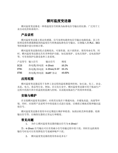
横河温度变送器横河温度变送器是一种将温度信号转换为标准电信号输出的仪器,广泛用于工业自动化控制系统中。
产品说明横河温度变送器主要由传感器、信号处理电路和电信号输出电路组成。
其工作原理是将传感器测量到的温度信号转换成标准电信号输出,以便输入到PLC、DCS等控制器中进行控制计算。
横河温度变送器的优点是精度高、可靠性强、抗干扰性好、使用寿命长等。
同时,横河温度变送器还具有多种保护功能,如反接保护、过电压保护、过电流保护等,可有效保护仪器设备和工业系统。
产品型号输入信号输出信号精度SC25 热电偶/热电阻4-20mA ±0.2%ST81 热电偶/热电阻4-20mA/0-5V ±0.1%ST85 热电偶/热电阻HART协议±0.05%应用范围横河温度变送器适用于各种工业过程的温度测量和控制,如石油、化工、冶金、水泥、电力、食品等行业。
例如,在石化行业中,横河温度变送器可用于炼油生产过程中的蒸汽和介质温度的监测与控制,从而提高炼油生产的效率和质量。
安装与维护在安装横河温度变送器时,应将其安装在干燥通风处,并避免高温、高湿等环境。
同时,应按照产品说明书中的连接方式进行连接,以确保正确地采集和输出温度信号。
横河温度变送器在使用中应定期进行维护和检查,如清洁机壳和传感器、校准输出信号等,以确保仪器的正常运行和精度。
常见问题1.为什么横河温度变送器的输出信号为4-20mA?答:4-20mA信号输出可以有效减小信号传输过程中的干扰,同时在远距离传输信号时也可以有效降低信号衰减和噪声干扰。
2.横河温度变送器的使用寿命是多长?答:横河温度变送器的使用寿命通常为5-10年左右,具体寿命取决于使用环境和使用方式等因素。
总结横河温度变送器是一种重要的温度测量和控制仪器,广泛应用于各个工业行业中。
其具有高精度、可靠性强、抗干扰性好等优点,可以有效提高工业生产效率和产品质量。
在使用横河温度变送器时,应遵循产品说明,并定期进行维护和检查,以确保其正常运行和精度。
日本横河UT32A温控表
方法 服务器
网关
子设备 子设备 Modbus 主机功能
多分支
母 / 子设备
子设备
接口 以太网 以太网 +RS-485
RS-485 RS-485
目标 PLC 及其它
RS-485: UT35A/UT32A*1 PLC 及其它, UT35A/UT32A*2
PLC 及其它
RS-485
UT35A/UT32A
RS-485(仅 2 线) UT35A/UT32A
400m (0.5M)
200m (1.5M)
100m(3M 至 12M)
*3: AUTO 自动设置为主控制器(PROFIBUS-DP 主机)的波特率。
All Rights Reserved. Copyright © 2010 , Yokogawa Electric Corporation
GS 05P01D31-01ZH 2010.01.05-00
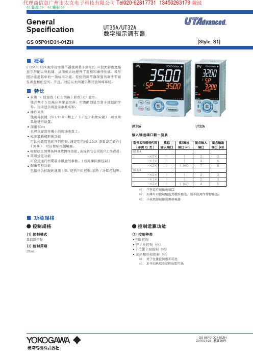
UT35A
UT32A
输入输出端口数一览表
型号名和规格代码 ( 参阅 12 页 )
UT35A -×0× -×1× -×2×
UT32A -×0× -×1× -×2×
模拟 输入端口
1 1 1
1 1 1
模拟输出 端口 (*1)
1 1 1 (*2)
1 1 1 (*2)
接点输入 接点输出 端口 端口 (*3)
2
最大通信距离:1200m
终端电阻器:220Ω(外部)
PROFIBUS-DP
标准:现场总线 (IEC61158)
相应版本:DP V0
波特率:9.6k, 19.2k, 45.45k, 93.75k, 187.5k, 0.5M, 1.5M, 3M, 6M, 12M, AUTO (*3)
E+H温度变送器选型样本

TI256T/02/en 71073145Technical InformationOmnigrad M TR10Modular RTD assemblyprotection tube and neck tube, threadApplication •Universal range of application•Measuring range: -200...600 °C (-328...1112 °F)•Pressure range up to 50 bar (725 psi)•Degree of protection: up to IP 68Head transmittersAll Endress+Hauser transmitters are available with enhanced accuracy, reliability and cost effectiveness compared to directly wired sensors. Easy customizing by choosing one of the following outputs and protocols:•Analog output 4...20 mA •HART ®•PROFIBUS ® PA•FOUNDATION Fieldbus™Your benefits•High flexibility due to modular assembly with standard terminal heads and customized immersion length •Highest possible compatibility with a design according to DIN 43772•Neck tube for heat protection of head transmitter •Fast response time with reduced/tapered tip form •Types of protection for use in hazardous locations:Intrinsic Safety (Ex ia)Non-Sparking (Ex nA)4 0TR102Endress+HauserFunction and system designMeasuring principleThe Resistance Temperature Detector (RTD) element has an electrical resistance with a value of 100 Ω at 0 °C (32 °F). It is commonly known as Pt100 and complies with IEC 60751. This resistance value increases at higher temperatures according to the characteristics of the resistor material (platinum). These kind of sensors are called Positive Temperature Coefficient elements (PTC).The coefficient is fixed with α = 0.00385 °C -1, calculated between 0 and 100 °C (32 and 212 °F), according to ITS90 (International Temperature Scale 1990).Wire wound platinum resistance thermometers (WW) consist of hair thin highly purified platinum wire double wound inside a ceramic carrier. This is then sealed top and bottom with a ceramic protective layer. Themeasurements achieved by these resistance thermometers are not only highly reproducible, but also show long term resistance/temperature characteristic stability within temperature ranges up to 600 °C (1112 °F). This sensor type is relatively large in its dimensions and is also not very resistant to vibration.Thin film platinum resistance thermometers (TF) consist of a precise amount of platinum which is vaporized under vacuum onto a ceramic substrate to a thickness of 1 μm. This is then protected by a glass layer. The advantages are: smaller dimensions than wire wound and greatly improved vibration resistance. Thin film resistances (TF) are flat, microscopic versions of the wire wound types (WW) with a measurement relevant difference:The temperature expansion behavior of the different layers of this structure leads to minimal mechanical stress. Temperature changes in thin film resistances (TF) cause the desired temperature relevant changes of the resistance as well as minimal tension stress related resistance changes. Through this the resistance/temperature characteristic of most thin film platinum resistance thermometers (TF) differs considerably from the standard characteristics at higher temperatures. Thin film resistances are therefore used for temperature measurement in ranges below 500 °C (932 °F).Measuring systemExample of an applicationA Built-in RTD assembly TR10 with head transmitter BRIA261 Field display–The display measures an analog measurement signal and indicates this on the display. The display is connected in a 4 to 20mA current loop and also derives its supply from the loop. The voltage drop is almost negligible (<2.5V). The dynamic internal resistance (load) makes sure that independently from the loop current, the maximum voltage drop is never exceeded. The analog signal at the input is digitalized, analyzed, and shown in the rear illuminated display. For details see Technical Information (see chapter "Documentation").CActive barrier RN221N–The RN221N active barrier (24 V DC, 30 mA) has a galvanically isolated output for supplying voltage to loop powered transmitters. The power supply has a wide-range input for mains power, 20 to 250V DC/AC,50/60Hz to be used in any electrical circuit. For details see Technical Information (see chapter "Documentation").TR10Endress+Hauser 3Equipment architectureEquipment architecture of the Omnigrad M TR10The Omnigrad M TR10 RTD assemblies are modular. The terminal head serves as a connection module for the protection armature in the process as well as for the mechanical and electrical connection of the measuring insert. The actual RTD sensor element is fitted in and mechanically protected within the insert. The insert can be exchanged and calibrated even during the process. Either ceramic terminal blocks or transmitters can be fitted to the internal base washer. Where required, threads or compression fittings can be fixed onto the protection armature.Measurement range-200 ... 600 °C (-328...1112 °F) according to IEC 60751Performance characteristicsOperating conditionsAmbient temperature12Insert (∅ 3 mm, 0.12 in) with mounted head transmitter, for exampleInsert (∅ 6 mm, 0.24 in) with mounted ceramic terminal block, for example 66a 6b Various tip shapes - detailed information see chapter ’tip shape’:Reduced or tapered for inserts with ∅ 3 mm (0.12 in)Straight or tapered for inserts with ∅ 6 mm (0.24 in)3Terminal headE Neck tube4Protection armatureL Immersion length5Threads as process connectionIL Insertion length = E + L + 10 mm (0.4 in)Terminal headTemperature in °C (°F)Without mounted head transmitter •Housing, material aluminum -40 to 100 ºC (-40 to 212 °F)•Housing, material polyamide -40 to 85 °C (-40 to 185 °F)With mounted head transmitter-40 to 85 °C (-40 to 185 °F)With mounted head transmitter and display -20 to 70 °C (-4 to 158 °F)TR10Process pressureThe pressure values to which the protection tube can be subjected at the various temperatures are illustratedby the figures below.Maximum permitted process pressure for tube diameter–Tube diameter 9 x 1 mm (0.35 in) -----------–Tube diameter 12 x 2.5 mm (0.47 in) - - - - - -A Medium water at T = 50 °C (122 °F)L Immersion lengthB Medium superheated steam at T = 400 °C (752 °F)P Process pressureMaximum flow velocityThe highest flow velocity tolerated by the protection tube diminishes with increasing immersion lengthexposed to the stream of the fluid. Detailed information may be taken from the figures below.Flow velocity depending on the immersion length–Tube diameter 9 x 1 mm (0.35 in) -----------–Tube diameter 12 x 2.5 mm (0.47 in) - - - - - -A Medium water at T = 50 °C (122 °F)L Immersion lengthB Medium superheated steam at T = 400 °C (752 °F)v Flow velocityShock and vibration resistance4g / 2 to 150 Hz as per IEC 60068-2-64Endress+HauserTR10Endress+Hauser 5AccuracyRTD corresponding to IEC 60751!Note!For measurement errors in °F, calculate using equations above in °C, then multiply the outcome by 1.8.Response timeTests in water at 0.4 m/s (1.3 ft/s), according to IEC 60751; 10 K temperature step changes:!Note!Response time for the sensor assembly without transmitter.Insulation resistanceInsulation resistance ≥100 M Ω at ambient temperature.Insulation resistance between each terminal and the sheath is tested with a voltage of 100 V DC.1)|t| = absolute value °CProtection tube DiameterResponse time Reduced tip ∅ 5.3 mm (0.2 in)Tapered tip∅ 6.6 mm (0.26 in) or ∅ 9 mm (0.35 in)Straight tip9 x 1 mm (0.35 in)t 50t 907.5 s21 s 11 s 37 s 18 s 55 s 11 x 2 mm (0.43 in)t 50t 907.5 s 21 s not available not available 18 s 55 s 12 x 2.5 mm (0.47 in)t 50t 90not available not available11 s 37 s38 s 125 sTR106Endress+HauserSelf heatingRTD elements are not self-powered and require a small current be passed through the device to provide a voltage that can be measured. Self-heating is the rise of temperature within the element itself, caused by the current flowing through the element. This self-heating appears as a measurement error and is affected by the thermal conductivity and velocity of the process being measured; it is negligible when an Endress+Hauser iTEMP ® temperature transmitter is connected.Calibration specificationsThe manufacturer provides comparison temperature calibration from -80 to +600 °C (-110 °F to 1112 °F) based on the International Temperature Scale of 1990 (ITS90). Calibrations are traceable to national and international standards. The calibration report is referenced to the serial number of the thermometer.MaterialTransmitter specificationsInsert-Ø:6 mm (0.24 in) and 3 mm (0.12 in)Minimum insertion length IL in mm (inch)Temperature rangewithout head transmitterwith head transmitter -80 °C to -40 °C (-110 °F to -40 °F)200 (7.87)-40 °C to 0 °C (-40 °F to 32 °F)160 (6.3)0 °C to 250 °C (32 °F to 480 °F)120 (4.72)150 (5.9)250 °C to 550 °C (480 °F to 1020 °F)300 (11.81)550 °C to 650 °C (1020 °F to 1202 °F)400 (15.75)Material Short description max. application temperature Features and benefits SS 316L/1.4404X2CrNiMo 17 13 2800 °C (1472 °F)•Austenitic, stainless steel •High corrosion resistance•High resistance at low temperatures•Optimal corrosion resistance in an acid, non oxydizing environment(e.g. phosphorous and sulphuric acids in low concentration and at low temperatures)•Not resistant to chloride at high temperatures SS 316Ti/1.4571X6CrNiMoTi 17 12 2800 °C (1472 °F)•Austenitic, stainless steel •High corrosion resistance•High resistance at low temperatures•Optimal corrosion resistance in an acid, non oxydizing environment (e.g. phosphorous and sulphuric acids in low concentration and at low temperatures)•Not resistant to chloride at high temperaturesHastelloy ® C276/2.4819NiMo 16 Cr 15 W 600 °C (1112 °F)•Specially high resistance against aggressive oxydizing and reducing media, even at high tempe-ratures.•Especially resistant against: sulphuric acid, high chloride contents, hot concentrated acetic acid chloride, chrome acetic acids, copper chloride, metal chloride TMT180PCP Pt100TMT181PCP Pt100, TC, Ω, mVTMT182HART ®Pt100, TC, Ω, mVTMT84 PA / TMT85 FF Pt100, TC, Ω, mVMeasurement accuracy0.2 °C (0.36 °F), optional 0.1 °C (0.18 °F) or 0.08%0.2 °C (0.36 °F) or 0.08%0.1 °C (0.18 °F)% is related to the adjusted measurement range (the larger value applies)Sensor current Ι ≤ 0.6 mAΙ ≤ 0.2 mAΙ ≤ 0.3 mAGalvanic isolation (input/output)-Û = 3.75 kV ACU = 2 kV ACTR10Endress+Hauser 7Transmitter long-term stability ≤ 0.1 °C/year (≤ 0.18 °F / year) or ≤ 0.05% / yearData under reference conditions; % relates to the set span. The larger value applies.System componentsFamily of temperature transmittersMeasurement assemblies with iTEMP ® transmitters are an installation ready solution to improve thefunctionality of temperature measurement by increasing accuracy and reliability when compared to direct wired sensors. Overall installation costs are lower than with direct wired sensors, since an inexpensive pair of signal (4 to 20 mA) wires can be run over long distances.PC programmable devices TMT180 and TMT181PC programmable head transmitters offer you extreme flexibility and help control costs with the ability to stock one device and program it for your needs. Regardless of your choice of output, all iTEMP ® transmitters can be configured quickly and easily with a PC. To help you with this task, Endress+Hauser offers free software ReadWin ® 2000 which can be downloaded from our website. Go to to download ReadWin ® 2000 today. Details see Technical Information (see chapter ’Documentation’).HART ® TMT182 head transmitterHART ® communication is all about easy, reliable data access and getting better information moreinexpensively. iTEMP ® transmitters integrate seamlessly into your existing control system and provide painless access to preventative diagnostic information.Configuration with a DXR275 or 375 hand-held or a PC with configuration program (FieldCare, ReadWin ® 2000) or configure with AMS or PDM. Details see Technical Information (see chapter ’Documentation’).PROFIBUS ® PA TMT84 head transmitterUniversally programmable head transmitter with PROFIBUS ® PA communication. Converting various input signals into a digital output signal. High accuracy over the complete ambient temperature range. Swift and easy operation, visualization and maintenance using a PC directly from the control panel, e. g. using operating software such as FieldCare, Simatic PDM or AMS. DIP switch for address setting, makes start up and maintenance safe and reliable.Benefits are: dual sensor input, highest reliability in harsh industrial environments, mathematic functions, thermometer drift monitoring, sensor back-up functionality, sensor diagnosis functions and sensor-transmitter matching using Callendar-Van Dusen coefficients. Details see Technical Information (see chapter ’Documentation’).!Note!The previous model PROFIBUS ® PA TMT184 head transmitter will be available for a transition time.FOUNDATION Fieldbus™ TMT85 head transmitterUniversally programmable head transmitter with FOUNDATION fieldbus™ communication. Converting various input signals into a digital output signal. High accuracy over the complete ambient temperature range. Swift and easy operation, visualization and maintenance using a PC directly from the control panel, e. g. using operating software such as ControlCare from Endress+Hauser or the NI Configurator from National Instruments.TR10Benefits are: dual sensor input, highest reliability in harsh industrial environments, mathematic functions,thermometer drift monitoring, sensor back-up functionality, sensor diagnosis functions and sensor-transmittermatching using Callendar-Van Dusen coefficients. Details see Technical Information (see chapter’Documentation’).Terminal heads All terminal heads have internal geometry according to DIN 43729, form B and thermometer connectionM24x1.5.All dimensions in mm (inch). All cable gland dimensions in the graphics are based on SKINTOP ST M20x1.58Endress+HauserTR10Endress+Hauser9TR1010Endress+HauserEndress+Hauser 11Protection tube All dimensions in mm (inches).Dimensions of the Omnigrad M TR10Tip shapeAvailable versions of protection tube tips (reduced, straight or tapered)AModel with terminal block mounted ∅ ID Insert diameterB Model with head transmitter mounted IL Insertion length = E + L + 10 mm (0.4 in)C Model with flying leads L Immersion lengthE Neck tube length ∅ X Protection tube diameterPos. No.Tip shape, L = Immersion length Insert Diameter M Reduced, L ≥ 70 mm (2.76 in)∅ 3 mm (0.12 in)R Reduced, L ≥ 50 mm (1.97 in)1)1)not with material Hastelloy ® C276/2.4819∅ 3 mm (0.12 in)S Straight∅ 6 mm (0.24 in)T Tapered, L≥ 90 mm (3.54 in)∅ 3 mm (0.12 in)W Tapered DIN43772-3G, L ≥ 115 mm (4.53 in)∅ 6 mm (0.24 in)12Endress+HauserWeightFrom 0.5 to 2.5 kg (1 to 5.5 lbs) for standard options.Process connectionSpare parts•A thermowell is available as spare part TW10 (see Technical Information in chapter ’Documentation’).•The RTD insert is available as spare part TPR100 (see Technical Information in chapter ’Documentation’).If spare parts are required, refer to the following equation: Insertion length IL = E + L + 10 mm (0.4 in)WiringWiring diagramsType of sensor connectionSpare partMaterial-No.Gasket M21-G½", copper 60001328Gasket M27-G¾", copper 60001344Gasket M33-G1", copper60001346Gasket set M24x1.5, aramid+NBR (10 pieces)60001329Endress+Hauser 13Installation conditionsOrientationNo restrictions.Installation instructionsInstallation examplesA - B: In pipes with a small cross section the sensor tip should reach or extend slightly past the center line of the pipe (= L).C - D:Tilted installation.The immersion length of the thermometer influences the accuracy. If the immersion length is too small then errors in the measurement are caused by heat conduction via the process connection and the container wall. If installing into a pipe then the immersion length must be at least half of the pipe diameter.•Installation possibilities: Pipes, tanks or other plant components•Minimum immersion length = 80 to 100 mm (3.15 to 3.94 in)The immersion length must be at least 8 times the protection tube diameter. Example: Protection tubediameter 12 mm (0.47 in) x 8 = 96 mm (3.8 in). Recommended standard immersion length according toDIN 43772: 120 mm (4.72 in)•ATEX certification: Always take note of the installation regulations!!Note!When operating in small nominal bore pipes it must be guaranteed that the protection tube tip is long enoughto extend past the pipe center line (see Pos. A and B). A further solution could be an angled (tilted) installation(see Pos. C and D). When determining the immersion length all thermometer parameters and the process tobe measured must be taken into account (e.g. flow velocity, process pressure).Neck tube length The neck tube is the part between the process connection and the housing. It is normally made of a tube withdimensional and physical characteristics (diameter and material) which are the same as of the tube in contactwith the medium.The connection situated in the upper part of the neck allows for orientation of the terminal head.As illustrated in the following figure, the neck tube length may influence the temperature in the terminal head.It is necessary that this temperature is kept within the limit values defined in the chapter "Operatingconditions".Heating of the terminal head consequent to the process temperature14Endress+HauserCertificates and approvalsCE Mark The device meets the legal requirements of the EC directives if applicable. Endress+Hauser confirms that thedevice has been successfully tested by applying the CE mark.Hazardous area approvals For further details on the available Ex versions (ATEX, CSA, FM, etc.), please contact your Endress+Hausersales organization. All relevant data for hazardous areas can be found in separate Ex documentation. If required,please request copies from us or your Endress+Hauser sales organization.Other standards and guidelines •IEC 60529:Degrees of protection by housing (IP-Code).•IEC 61010-1:Safety requirements for electrical measurement, control and laboratory instrumentation.•IEC 60751:Industrial platinum resistance thermometer•DIN43772:Protection tubes•EN 50014/18, DIN 47229:Terminal heads•IEC 61326-1:Electromagnetic compatibility (EMC requirements)PED approval The Pressure Equipment Directive (97/23/CE) is respected. As paragraph 2.1 of article 1 is not applicable tothese types of instruments, the CE mark is not requested for the RTD assembly destined for general use. Material certification The material certificate 3.1 (according to standard EN 10204) can be directly selected from the sales structureof the product and refers to the parts of the sensor in contact with the process fluid. Other types of certificatesrelated to materials can be requested separately. The "short form" certificate includes a simplified declarationwith no enclosures of documents related to the materials used in the construction of the single sensor andguarantees the traceability of the materials through the identification number of the thermometer. The datarelated to the origin of the materials can subsequently be requested by the client if necessary.Test on protection tube The pressure tests are carried out at ambient temperature in order to verify the resistance of the protection tubeto the specifications indicated by the norm DIN 43772. With regards to the protection tubes that do not complywith this norm (with a reduced tip, a tapered tip on a 9 mm (0.35") tube, special dimensions, ...), the pressureof the corresponding straight tube with similar dimensions is verified. The sensors certified for use in Ex Zones,are always tested to pressure according to the same criterions. Tests at different pressures can be carried outupon request. The liquid penetrant test verifies the absence of crevices on the weldings of the protection tube. Test report and calibration With regards to the tests and calibration, the "Inspection Report" consists of a compliance declaration for theessential points of the standard IEC 60751.The "Factory calibration" is carried out in an EA (European Accreditation) authorized laboratory ofEndress+Hauser according to an internal procedure. A calibration may be requested separately according to anEA accredited procedure (SIT calibration). Calibration is carried out on the thermometer insert.Endress+Hauser15Ordering informationProduct structure RTD thermometer TR10Approval:A Non-hazardous areaB ATEX II 1 GD EEx ia IICE ATEX II 1/2 GD EEx ia IICG ATEX II 1 G EEx ia IICH ATEX II 3 GD EEx nA IIK TIIS Ex ia IIC T4L TIIS Ex ia IIC T6Head; Cable Entry:B TA30A Alu, IP66/IP68; M20C TA30A Alu, IP66/IP68; NPT ½"D TA30A Alu, IP66/IP67; M12 plug PAE TA21E Alu, screw cap IP65; M12 plug PAF TA30A Alu+display, IP66/IP68; M20G TA30A Alu+display, IP66/IP68; NPT ½"H TA30A Alu+display, IP66/IP67; M12 plug PAJ TA20J 316L, IP66/IP67; M20K TA20J 316L, + display, IP66/IP67; M20M TA20J 316L, IP66/IP67; M12 plug PAN TA20R 316L, screw cap IP66/IP67; M20 silicone freeO TA30D Alu, high cover, IP66/IP68; M20P TA30D Alu, high cover, IP66/IP68; NPT ½"Q TA30D Alu, IP66/IP67; M12 plug PAR TA20R 316L screw cap IP66/IP67; M20S TA20R 316L screw cap IP66; M12 plugT TA30A Alu, IP66/IP67; 7/8" plug FFU TA30A Alu+display, IP66/IP67; 7/8" plug FFV TA30D Alu, IP66/IP67; 7/8" plug FF7TA20B PA black, IP65; M20Pipe Diameter; Material:A9 mm; 316L, DIN43772-2GB11 mm; 316L, DIN43772-2GD9 mm; 316Ti, DIN43772-2GE11 mm; 316Ti, DIN43772-2GF12 mm; 316Ti, DIN43772-2G/3GG9 mm; Alloy C276, DIN43772-2GH11 mm; Alloy C276, DIN43772-2GNeck Length E:180 mm, DIN43772-2G282 mm, DIN43772-3G3145 mm, DIN43772-2G4147 mm, DIN43772-3G8... mm9..... mm, as specifiedProcess Connection:BG Thread M20; 316TiBH Thread G ½" A; 316TiBJ Thread G 1" A; 316TiCA Thread G ½"; 316LCB Thread G ¾"; 316LCC Thread G 1"; 316LCD Thread NPT ½"; 316LCE Thread NPT ¾"; 316LHD Thread NPT ½"; Alloy C276HH Thread G ½" A; Alloy C276JA Thread R ½"; JIS B 0203, 316LJB Thread R ¾"; JIS B 0203, 316L16Endress+HauserTip Shape:M Reduced, L ≥ 70 mmR Reduced, L ≥ 50 mmS StraightT Tapered, L ≥ 90 mmW Tapered DIN43772-3G, L ≥ 115 mmImmersion Length L:A70 mmC120 mmD160 mmE220 mmF250 mmG280 mmH310 mmJ400 mmK580 mmX... mmY..... mm, as specified150 mm260 mm480 mm5100 mmHead Transmitter; Range:B TMT84 PAC Terminal blockD TMT85 FFF Flying leadsG TMT181 (PCP); temp. range to be specifiedH TMT182 (HART); temp. range to be specified2TMT180-A21 fix; 0.2 K, temp. range to be specified, Span limit -200/650 °C3TMT180-A22 fix; 0.1 K, temp. range to be specified, Span limit -50/250 °C4TMT180-A11 PCP; 0.2 K, temp. range to be specified, Span limit -200/650 °C5TMT180-A12 PCP; 0.1 K, temp. range to be specified, Span limit -50/250 °CRTD; wire; meas. range; class; validity:A1x Pt100 WW; 3; -200/600 °C; A: -200/600 °CB2x Pt100 WW; 3; -200/600 °C; A: -200/600 °CC1x Pt100 WW; 4; -200/600 °C; A: -200/600 °CF2x Pt100 WW; 3; -200/600 °C; 1/3B; 0/250 °CG1x Pt100 WW; 3; -200/600 °C; 1/3B; 0/250 °CY Special version, to be specified21x Pt100 TF; 3; -50/400 °C; A; -50/250 °C increas. vibr. resistance31x Pt100 TF; 4; -50/400 °C; A; -50/250 °C increas. vibr. resistance61x Pt100 TF; 3; -50/400 °C; 1/3B; 0/150 °C increas. vibr. resistance71x Pt100 TF; 4; -50/400 °C; 1/3B; 0/150 °C increas. vibr. resistanceMaterial Certificate:0Not needed1EN10204-3.1 Material2EN10204-3.1 Material, shortformTest Report:A Internal hydrost. pressure testB External hydrost. pressure testC Dye penetrant test, TW welding0Not neededTest/Calibration:A0, 100 °C, RTD-SignalB0, 100 °C, RTD-Signal, 4-20 mA/loopC0, 100 °C, RTD-Signal, 2 SensorsE0, 100, 150 °C, RTD-SignalF0, 100, 150 °C, RTD-Signal, 4-20 mA/loopG0, 100, 150 °C, RTD-Signal, 2 Sensors0Not neededTR10-← Order code (complete)This ordering information can give an overview about the available order options. The Endress+Hauser salesorganization can provide detailed ordering information and information on the order code.Endress+Hauser17DocumentationTechnical Information:•RTD Insert for Temperature Sensor Omniset TPR100 (TI268t/02/en)•Thermowell for temperature sensors Omnigrad M TW10 (TI261t/02/en)•Temperature head transmitter iTEMP® PCP TMT181 (TI070r/09/en)•Temperature head transmitter iTEMP® Pt TMT180 (TI088r/09/en)•Temperature head transmitter iTEMP® HART® TMT182 (TI078r/09/en)•Temperature head transmitter iTEMP® TMT84 PA (TI138r/09/en)•Temperature head transmitter iTEMP® TMT85 FF (TI134r/09/en)Hazardous area supplementary documentation:•Omnigrad TRxx RTD Thermometer ATEX II1GDor II 1/2GD (XA072r/09/a3)•Omnigrad TRxx, Omniset TPR100, TET10x, TPC100, TEC10x ATEX II 3GD EEx nA (XA044r/09/a3) Application example Technical information:•Field display RIA261 (TI083r/09/en)•Active barrier with power supply RN221N (TI073R/09/en)Instruments InternationalEndress+HauserInstruments International AGKaegenstrasse 24153 ReinachSwitzerlandTel.+41 61 715 81 00Fax+41 61 715 25 00info@TI256T/02/en/08.0871073145FM+SGML 6.0 ProMoDo。
横河 UT50A说明书

• 阳光直射或靠近加热器的位置
将本仪表安装在接近常温 23°C,具有稳定温度的场所。切勿将其安装在阳光直射或
靠近加热器的位置。否则会对仪表造成不良影响。
• 有大量油烟、蒸汽、水分、灰尘或腐蚀性气体的场所
油烟、蒸汽、水分、灰尘或腐蚀性气体会对本仪表造成不良影响。
• 靠近电磁场发生源的地方
切勿在仪表附近摆放磁铁或能产生磁力的工具。如果在强电磁场发生源附近使用本
些特定的应用场所,包括核电站设备、使用放射能的设备、铁路设施、航空设施 和医疗设备等。如果在这样的环境下使用,则用户需自行负责在系统附加设备中 包括以及保证个人安全的设备。 (5) 严禁对产品改装。
警告
l 电源 在打开电源前,确保仪表的电源电压符合电源电压。
l 切勿在可燃性气体中使用本仪表 请不要在有可燃性气体、爆炸性气体或蒸气的场所操作本仪表,在这样 的环境下使用本仪表非常危险,在有高浓度的腐蚀性气体(H2S,SOX 等) 环境中长时间使用本仪表容易引起故障。
n UT55A
码
说明
UT55A
数字温度控制器
(具有传送输出或 15 V DC 回路电源、3 个 DI 端口、 3 个 DO 端口) (电源:100-240 V AC)
-0
类型 1: 基本控制
-1
-2
标准类型 位置比例类型 加热 / 冷却类型
0
无
远程(1 个附加辅助模拟)输入、6 个附加 DI、5 个
150 mm
备 使 用 1.43 mm 的 厚 钢 板 或 1.6 mm 厚 的 未 镀 层 钢 板
制 作 的 外 罩, 外 罩 与 设 备 顶 部、 底 部 和 侧 面 至 少 距 离 150 mm。
150 mm
- 1、下载文档前请自行甄别文档内容的完整性,平台不提供额外的编辑、内容补充、找答案等附加服务。
- 2、"仅部分预览"的文档,不可在线预览部分如存在完整性等问题,可反馈申请退款(可完整预览的文档不适用该条件!)。
- 3、如文档侵犯您的权益,请联系客服反馈,我们会尽快为您处理(人工客服工作时间:9:00-18:30)。
EMC Conformity Standards
,
EN61326, AS/NZS CISPR11
SIL Certification YTA110 temperature transmitter is certified by TU¨ V NORD CERT GmbH in compliance with the following standards; IEC 61508: 2000; Part1 to Part 7 Functional Safety of Electrical/electronic/programmable electronic related systems; SIL 2 capability for single transmitter use, SIL 3 capability for dual transmitter use.
Variety of sensor inputs The type of sensor thermocouples (T/C), RTDs, ohms, or DC milivolts.
Digital communication BRAIN or HART® communication protocol is available. The insturment configuration can be changed by the user with using the BT200 or HART communicator.
Power Supply Effect ±0.005 % of calibration span per volt
Vibration Effect 10 to 60 Hz 0.21 mm peak displacement 60 to 2000 Hz 3G
Position Effect None
ᮀ FUNCTIONAL SPECIFICATIONS
Communication Requirements
BRAIN:
Communication Distance Up to 2 km (1.25 miles) when using CEV polyethylene-insulated PVC-sheathed cables. Communication distance varies depending on type of cable used.
Input
Input type is selectable: Thermocouples, 2-, 3-, and 4-wire RTDs, ohms and DC milivolts. See Table 1. on page 3.
Span & Range Limits See Table 1. on page 3.
■ STANDARD SPECIFICATIONS
ᮀ PERFORMANCE SPECIFICATIONS
Accuracy (A/D accuracy/span + D/A accuracy) or Ϯ 0.1 % of calibrated span, whichever is greater. See Table 1. on page 3.
2
Load Capacitance 0.22 F or less
Load Inductance 3.3 mH or less
Isolation Input/Output/GND isolated to 500 V DC
Yokogawa Electric Corporation 2-9-32 Nakacho, Musashino-shi, Tokyo, 180-8750 Japan Phone: 81-422-52-5690 Fax.: 81-422-52-2018
Damping Time Constant Selectable from 0 to 99 seconds
Ambient Temperature Limits Option code may affect limits. -40 to 85 ˚C (-40 to 185 ˚F) -30 to 80 ˚C (-22 to 176 ˚F) with Integral Indicator
5 Year Stability RTD: Ϯ0.2% of reading or Ϯ0.2°C, whichever is greater at 23Ϯ2°C. T/sC: Ϯ0.4% of reading or Ϯ0.4°C, whichever is greater at 23Ϯ2°C.
RFI Effect Tested per EN 50082-2, field intensity up to 10 V/m.
Output in Transmitter Failure High (21.6 mA DC or more) or Low (3.2 mA DC or less).
Update Time Approximately 0.5 seconds
Turn-on Time Approximately 5 seconds
Supply & Load Requirements
Supply Voltage 10.5 to 42 V DC for general use and flameproof type 10.5 to 32 CV DC for lightning protector (Optional
code /A) 10.5 to 30 V DC for intrinsically safe, Type n,
GS 01C50B01-00E ©Copyright June 1998 13th Edition Aug. 2006
<<Contents>> <<Index>>
Sensor Burnout High (21.6 mA DC) or Low (3.6 mA DC), userselectable.
Stability RTD: Ϯ0.1% of reading or Ϯ0.1°C per 2 years, whichever is greater at 23Ϯ2°C.
T/C: Ϯ0.1% of reading or Ϯ0.1°C per year, whichever is greater at 23Ϯ2°C.
nonincendive, or non-sparking type Minimum voltage limited at 16.4 V DC for digital
communications, BRAIN and HART® protocols
Load
0 to 1335 ⍀ for operation 250 to 600 ⍀ for digital communication See Figure 1. on page 4.
Input signal source resistance (for T/C, mV) 1 k⍀ or lower
Input lead wire resistance (for RTD, ohm) 10 ⍀ per wire or lower
Output Two wire 4 to 20 mA DC. Output range: 3.68 mA to 20.8 mA BRAIN or HART ® protocol is superimposed on the 4 to 20 mA signal. Any single value from the followings can be selected as the analog output signal. Sensor 1, Terminal Temperature. Also, up to three of the above values can be displayed on LCD display or read via communication.
Cold Junction Compensation Accuracy (For T/C only) ± 0.5˚C (± 0.9 ˚F)
Ambient Temperature Effect (per 10 ˚C change) ± 0.1 % or ± (Temperature Coefficient /span), whichever is greater. See Table 2. for Temperature Coefficient.
Self-calibration The analog-to-digital measurement circuitry automatically self-calibrates for temperature update by comparing the dynamic measurement to extremely stable and accurate internal reference elements.
Self-diagnostics Loss of input error, ambient temperature error, EEPROM error, and CPU error. Up to four error history can be stored in the memory.
Manual Output Function The output value can be set manually.
■ FEATURES
High performance Microprocesser-based sensing technology ensures long-term accuracy and high reliability.