抽油烟机线路板说明书
典型吸油烟机电路的识图方法,一看就懂

典型吸油烟机电路的识图方法,一看就懂普通双电动机吸油烟机电路图4-16所示是一种典型的普通双电机吸油烟机电路。
该电路的核心元器件是电动机M1、M2,运转电容C1、C2,辅助元器件是琴键开关(组合开关)S,熔丝管FU1~FU3,指示灯EL。
图4-16 普通双电机吸油烟机电路按下琴键开关S内的照明灯按键,照明灯EL的供电回路被接通,EL开始发光;按下左风道键或右风道键,接通左风道风机M1或右风道风机M2的供电回路,在运转电容C1或C2的配合下M1或M2开始运转,进行排污;当按下双风道按键时,M1和M2同时转动进行抽油烟;当按下停止键后,各按键自动复位,照明灯熄灭,电动机停转,整机停止工作,进入关机状态。
FU1是普通熔丝管,当电动机或运转电容发生短路引起大电流时,FU1过电流熔断,实现过电流保护。
FU2、FU3是温度型熔丝管。
当M1、M2或其运转电容异常使它的表面温度升高并达到85℃时,FU3或FU2熔断,切断电动机供电线路,以免扩大故障,实现过热保护。
普通单电动机型吸油烟机电路下面以方邦CXW-160-136型吸油烟机电路为例,介绍普通单电机型吸油烟机电路的识图方法。
该电路的核心元器件是可变速电动机、启动电容,辅助元器件是照明灯、功能开关,如图4-17所示。
图4-17 方邦CXW-160-136型吸油烟机电路1.吸油烟电路在油烟较少时,按下慢速按键,市电电压通过慢速键的触点为电动机的慢速供电端子供电,电动机在启动电容(运行电容)的配合下低速运转,将油烟排到室外。
当油烟较多时按下快速按键,市电电压通过快速键的触点为电动机的快速供电端子供电,电动机在启动电容的配合下高速运转,将油烟快速排到室外。
风扇电动机运转时,按一下电动机开关键,电动机开关键断开,电动机失去供电而停转。
2.照明灯电路按下照明开关键,照明灯的供电回路被接通,照明灯获得供电后被点亮。
3.过热保护电路电动机内置了热保护器。
当电动机或运行电容发生短路产生大电流,使电动机表面的温度升高,被热保护器识别后动作,它的触点断开,实现过热保护功能。
烟机控制器规格书(显示型)
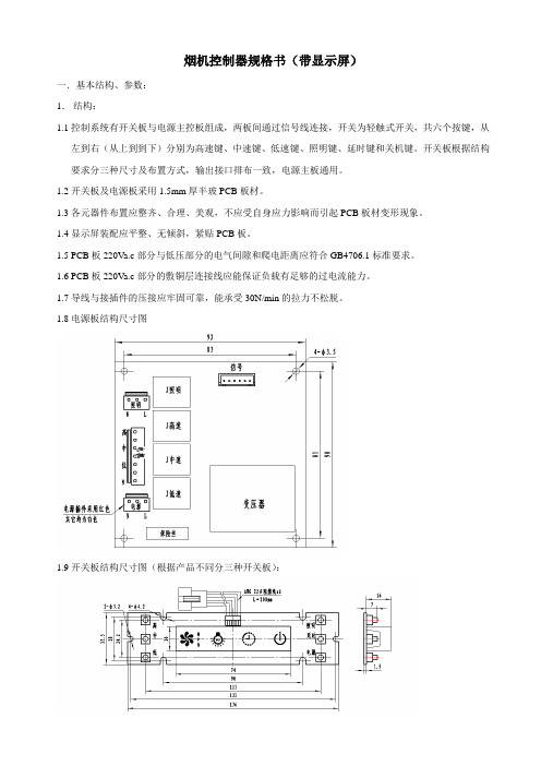
烟机控制器规格书(带显示屏)一.基本结构、参数:1.结构:1.1控制系统有开关板与电源主控板组成,两板间通过信号线连接,开关为轻触式开关,共六个按键,从左到右(从上到到下)分别为高速键、中速键、低速键、照明键、延时键和关机键。
开关板根据结构要求分三种尺寸及布置方式,输出接口排布一致,电源主板通用。
1.2开关板及电源板采用1.5mm厚半玻PCB板材。
1.3各元器件布置应整齐、合理、美观,不应受自身应力影响而引起PCB板材变形现象。
1.4显示屏装配应平整、无倾斜,紧贴PCB板。
1.5 PCB板220Va.c部分与低压部分的电气间隙和爬电距离应符合GB4706.1标准要求。
1.6 PCB板220Va.c部分的敷铜层连接线应能保证负载有足够的过电流能力。
1.7导线与接插件的压接应牢固可靠,能承受30N/min的拉力不松脱。
1.8电源板结构尺寸图1.9开关板结构尺寸图(根据产品不同分三种开关板):1.10开关板与电源板连接线1. 11上述电源板的元器件布置仅供参考,具体可按设计需要调整,但尺寸应符合要求。
2.基本参数:2.1额定输入工作电压:220V a.c;可工作电压范围:0.8倍~1.1倍额定工作电压。
2.2风机额定工作电压:220V a.c;驱动器件7A继电器。
2.3照明额定工作电压:220V a.c;驱动器件3A继电器。
2.4高速、中速、低速档继电器切换延时时间:0.1s。
2.5按键响应有效时间:0.15s≤T≤0.3s;按键为下压时有效。
2.6按键提示声时间: ≤1.5s。
2.7延时关机时间:3min±3s。
2.8变压器空载电流≤25mA;带载运行温升≤35K。
二.按键功能及显示要求:1、按键说明:1.1“电源”键:按键进入启动状态,5s内如无键操作则自动退出到待机状态。
1.2“高速”键:开启和关闭风机的高速档,为循环开/关方式,并与“中速”及“低速”键互锁。
“延时”键:工作状态下按键1次1.3“中速”键:开启和关闭风机的中速档,为循环开/关方式,并与“高速”及“低速”键互锁。
万家乐吸油烟机使用说明书
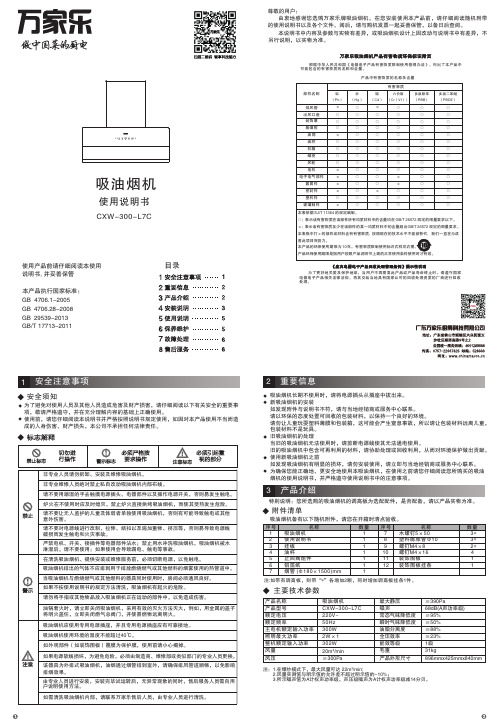
尊敬的用户:由衷地感谢您选购万家乐牌吸油烟机。
在您安装使用本产品前,请仔细阅读随机附带的使用说明书以及各个文件。
阅后,请与购机发票一起妥善保管,以备日后查阅。
本产品执行国家标准:GB4706.28-2008GB29539-2013GB/T 17713-2011GB 4706.1-2005吸油烟机使用说明书使用产品前请仔细阅读本使用说明书, 并妥善保管为了避免对使用人员及其他人员造成危害及财产损害,请仔细阅读以下有关安全的重要事项,敬请严格遵守,并在充分理解内容的基础上正确使用。
使用前,请您仔细阅读本说明书并严格按照说明书规定使用,如因对本产品使用不当而造成的人身伤害、财产损失,本公司不承担任何法律责任。
安全须知本说明书中内容及参数与实物有差异,或吸油烟机设计上因改动与说明书中有差异,不另行说明,以实物为准。
重要信息吸油烟机长期不使用时,请将电源插头从插座中拔出来。
新吸油烟机的安装如发现附件与说明书不符,请与当地经销商或服务中心联系。
请以环保的态度处置可回收的包装材料,以保持一个良好的环境。
请勿让儿童玩耍塑料薄膜和包装箱,这可能会产生窒息事故,所以请让包装材料远离儿童,包装材料不是玩具。
旧吸油烟机的处理当旧的吸油烟机无法使用时,请剪断电源线使其无法通电使用。
旧的吸油烟机中包含可再利用的材料,请协助处理或回收利用,从而对环境保护做出贡献。
使用新吸油烟机之前如发现吸油烟机有明显的损坏,请勿安装使用,请立即与当地经销商或服务中心联系。
为确保您能正确地、更安全地使用本吸油烟机,在使用之前请您仔细阅读您所购买的吸油烟机的使用说明书,并严格遵守使用说明书中的注意事项。
产品中有害物质的名称及含量根据中华人民共和国《电器电子产品有害物质限制使用管理办法》,列出了本产品中可能包含的有害物质的名称和含量。
为了更好地关爱及保护地球,当用户不再需要此产品或产品寿命终止时,请遵守国家电器电子产品相关法律法规,将其交给当地具有国家认可的回收处理资质的厂商进行回收处理。
【最新】油烟机电机接线图

【最新】油烟机电机接线图抽油烟机其实现在很多家庭都在使用抽油烟机这样的厨卫电器产品,当然有了它能给我们的厨房带来一定的新鲜空气,而且还可以帮助排除我们厨房的废气哦,可以说是一举两得。
在安装的时候一定要注意电机的接线问题,下面就给大家介绍一下抽油烟机电机接线图及分析。
抽油烟机电机接线图及分析要保证接线准确无误,最好用万用表R_10档来测试电机绕组的直流电阻,根据绕组出线的直流电阻值进行判断接线。
首先确定启动绕组,可以用万用表测量,与黑色电阻最大的那条就是启动绕组(电容线),与黑色电阻最小的为高速,阻值居中的为低速,红-1速(高)蓝-2速(低)黄-电容黑-电容-零线就是黑色,黄色接电容,黑色再接电源其中一条线,电源另外一条线接双速开关上分成二个速度。
一般的电机有4根引出线。
1,用万用表R_10档找出其中电阻值最大的两根线,在标准产品中,此二线一般以蓝、黑为代表,对于引出线之间直流电阻值要进行比较,辨别出R 值最大的两根。
并把电容器的两个端子连接到这两根线上。
2、把连接电容器的这两根线的其中一根(蓝线,或黑线)接到电源的零线(公共端子)上。
3、把剩余的两根导线分别且任意地接到油烟机的“快慢”档上,这两根线是电源的火线,快慢档就是用开关来控制电机的火线端子,(试机时如果快慢相反,对调快慢引出线在开关上的位置就可)。
4,接好后可以通电试验,此时可能电机会反转,出现此情况把接电容器的两根电机引出线对调就行了,一切正常后就可以进一步处理引线的绝缘和布线。
5.电源进线L为红色线,N为黑色线,两只照明灯的黑色线通到控制板,照明灯的另一端是蓝色线铰接在一起,从控制板出来3根线,分别是红色线、黑色线、白色线,这3根线中必定有1根是照明灯控制线,于是把照明灯的两根蓝色线和控制板出来的白色线连接,插上电源插头,控制板显示屏亮,照明灯不亮,按下控制板照明灯按钮,照明灯点亮,说明照明灯接线正确。
总结:以上就是对抽油烟机电机接线图以及分析的介绍,不知道大家都了解了多少呢,是不是心里已经有了一定的数,如果以后遇到这类问题是不是可以自己动手试一试呢?希望能对大家有一定的帮助。
除油烟机 安装及说明书
除 油 煙 機高排煙力以讓您使用得更舒適、更清靜。
安裝及使用前,請先詳細閱讀此說明書。
感謝您對本產品的惠顧,本系列產品始終秉持親愛的顧客:最佳的品質及完善的服務外,並追求低噪音及※本說明書內示意圖樣僅供參考,實際以實體為主。
安裝完畢後,請務必將此說明書交給顧客妥善保管。
若對本產品有任何使用上的疑問或需服務的地方請洽各區代理商服務站。
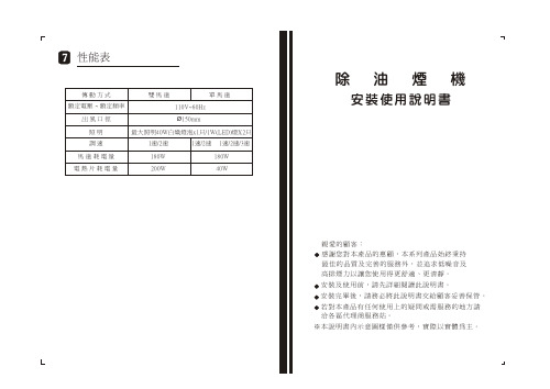
安裝使用說明書性能表傳 動 方 式 雙 馬 達 單 馬 達額定電壓出 風 口 徑 Ø150mm照 明 最大照明40W白熾燈泡x1只/1W(LED)燈X2只~ 額定頻率110V~60Hz調 速 1速/2速 1速/2速 1速/2速/3速 馬 達 耗 電 量 180W 180W 電 熱 片 耗 電 量 200W 40W二. 按裝施工說明.............P3四. 使用注意事項.............P5一. 按 裝 原 則...............P2 三. 使用方法.................P4七. 性能表..................P7五. 保 養.................P5六. 異常狀況之處理...........P6異常狀況之處理使用中發現異常狀況時,請將電源插頭拔掉,並就近洽經銷商或服務站或具專業資格人員至府上維修。
處理異常狀況時請將開關電源關掉。
異常狀況原 因 及 處 置 方 法電源線損壞請就近洽經銷商或服務站或具有專業資格人員至府上維修。
電源線規格:300V 0.75mm2*3c。
插頭規格:125V 7A 兩扁一圓插頭。
馬達不轉A. 查看開關或插頭接觸是否正常。
B. 查看燈泡是否會亮以確定電源是否正常。
C. 拆下保護網,用手轉動風葉,如轉不動則查看風葉是否 卡住。
若是,則請更換整組馬達。
D.如風葉用手輕動皆能運轉自如,則是電容器的問題:1.先查看電容器與馬達接線是否脫落。
2.若接線正常,就是電容器損壞,必須更換電容器。
A70 半嵌入式抽油烟机 中文操作手册说明书
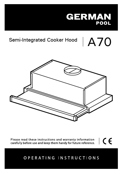
A70 Semi-Integrated Cooker HoodINDEXRECOMMENDATIONS AND SUGGESTIONS (3)CHARACTERISTICS (6)INSTALLATION (7)USE (9)MAINTENANCE (10)RECOMMENDATIONS AND SUGGESTIONSThe Instructions for Use apply to several versions of this appliance.Accordingly, you may find descriptions of individual features that do not apply to your specific appliance.INSTALLATION•The manufacturer will not be held liable for any damages resulting from incorrect or improper installation.• The minimum safety distance between the cooker topand the extractor hood is 650 mm (some models canbe installed at a lower height, please refer to theparagraphs on working dimensions and installation).• Check that the mains voltage corresponds to thatindicated on the rating plate fixed to the inside of thehood.• For Class I appliances, check that the domesticpower supply guarantees adequate earthing.Connect the extractor to the exhaust flue through a pipe of minimum diameter Ø 125 /5” , Ø 152/6” . The route of the flue must be as short as possible. • Do not connect the extractor hood to exhaust ducts carrying combustion fumes (boilers, fireplaces, etc.).• If the extractor is used in conjunction with non-electrical appliances (e.g. gas burningappliances), a sufficient degree of aeration mustbe guaranteed in the room in order to prevent thebackflow of exhaust gas. The kitchen must havean opening communicating directly with the openair in order to guarantee the entry of clean air.When the cooker hood is used in conjunction withappliances supplied with energy other than electric, the negative pressure in the room must not exceed 0,04 mbar to prevent fumes being drawn back into the room by the cooker hood.• In the event of damage to the power cable, it must be replaced by the manufacturer or by the technical service department, in order to prevent any risks.• If the instructions for installation for the gas hob specify a greater distance specified above, this has to be taken into account. Regulations concerning the discharge of air have to be fulfilled.• Use only screws and small parts in support of the hood.Warning: Failure to install the screws or fixing device in accordance with these instructions may result in electrical hazards.• Connect the hood to the mains through a two-pole switch having a contact gap of at least 3 mm.USE•The extractor hood has been designed exclusively for domestic use to eliminate kitchen smells.• Never use the hood for purposes other than for which it has been designed. • Never leave high naked flames under the hood when it is in operation. • Adjust the flame intensity to direct it onto the bottom of the pan only, making sure that it does not engulf the sides.• Deep fat fryers must be continuously monitoredduring use: overheated oil can burst into flames.• Do not flambè under the range hood; risk of fire.• This appliance can be used by children aged from8 years and above and persons with reducedphysical, sensory or mental capabilities or lack ofexperience and knowledge if they have been given supervision or instruction concerning use of the appliance in a safe way and understand the hazards involved. Children shall not play with the appliance. Cleaning and user maintenance shall not be made by children without supervision.• “CAUTION: Accessible parts may become hot when used with cooking appliances.”MAINTENANCE•Switch off or unplug the appliance from the mains supply before carrying out any maintenance work.• Clean and/or replace the Filters after the specified time period (Fire hazard). • The Grease filters must be cleaned every 2 months of operation, or more frequently for particularly heavy usage, and can be washed in a dishwasher. • The Activated charcoal filter is not washable and cannot be regenerated, and must be replaced approximately every 4 months of operation, or more frequently for particularly heavy usage.• Clean the hood using a damp cloth and a neutral liquid detergent.The symbol on the product or on its packaging indicates that this product may not be treated as household waste. Instead it shall be handed over to the applicable collection point for the recycling of electrical and electronic equipment. By ensuring this product is disposed of correctly, you will help prevent potential negative consequences for the environment and human health, which could otherwise be caused by inappropriate waste handling of this product. For more detailed information about recycling of this product, please contact your local city office, your household waste disposal service or the shop where you purchased the product.CHARACTERISTICSDimensionsComponentsRef. Q.ty Product Components1 1 Hood Body, complete with: Controls, Light, Blower,Filters8 1 Directional Air Outlet grille9 1 Reducer Flange Ø 125 / Ø 15220 1 Closing elementRef. Q.ty Installation Components12a 4 Screws 4,2 x 44,412b 2 Screws 4,2 x 12,712e 2 Screws 2,9 x 9,5Q.ty Documentation1Instruction ManualINSTALLATIONDrilling the Support surface and Fitting the HoodSCREW FITTING• The hood support surface must be 135 mm above the bottom surface of the wall units.• Drill the support with a ø 4,5 mm drill bit, using the drilling template provided.• Cut a hole ø 150 mm in size on the support surface, using the drilling template provided.• Fix using the 4 screws 12a (4,2 x 44,4) provided.SNAP-ON FITTING• The hood can be installed either directly on the bottom surface of the wall units using snap-on side supports.• Cut a fitted opening in the bottom surface of the wall unit, as shown.• Insert the hood until the side supports snap into place.• Lock in position by tightening the screws Vf from underneath the hood.Hood Type 45 50 55 60 70 80 90 L1360 410 460 510 610 710 810CLOSING ELEMENT• The space between the edge of the hood and the rear wall can be closed by applying the element 20provided, using the screws 12b.ConnectionsDUCTED VERSION AIR EXHAUST SYSTEM When installing the ducted version, connect the hood toor ø125 mm, the choice of which is left to the installer. • To install a ø 125 mm air exhaust connection, insert the reducer flange 9 on the hood body outlet.• Fix the pipe in position using sufficient pipe clamps (not supplied).• Remove possible charcoal filters.RECIRCULATION VERSION AIR OUTLET• Cut a hole ø 125 mm in any shelf that may be posi-tioned over the hood.• Insert the reducer flange 9 on the hood body outlet. • Connect the flange to the outlet on the shelf over the hood by using a flexible or rigid pipe ø125 mm. • Fix the pipe in position using sufficient pipe clamps (not supplied).• Fix the air outlet grid 8 on the recirculation air outlet by using the 2 screws 12e (2,9 x 9,5) provided. • Ensure that the activated charcoal filters have beeninserted.zELECTRICAL CONNECTION• Connect the hood to the mains through a two-pole switch having a contact gap of at least 3 mm.• When opening the sliding carriage for the first time after installing the hood, pull it out briskly until it clicks.USEControl panelL Light Switches the lighting systemon and off.M Motor Switches the extractor motoron and off.V Speed Sets the operating speed of theextractor:1. Low speed, used for a con-tinuous and silent airchange in the presence oflight cooking vapour.2. Medium speed, suitable formost operating conditionsgiven the optimum treatedair flow/noise level ratio.3. Maximum speed, used foreliminating the highestcooking vapour emission,including long periods. LM Motor Switches the extractor motoron and off.V Speed Sets the operating speed of theextractor:1. Low speed, used for a con-tinuous and silent airchange in the presence oflight cooking vapour.2. Medium speed, suitable formost operating conditionsgiven the optimum treatedair flow/noise level ratio.MAINTENANCEter efficiency).• When refitting the filters, make sure that the handle is visible on the outside.• Close the sliding suction panel.MAINTENANCECharcoal filter (Recycling version)REPLACING CHARCOAL FILTERSWarning: Turn the lights off and wait until the lamps cool down before you change the odour filter.• These filters are not washable and cannot be regenerated, and must be replaced approximately every four months or more frequently by particularly heavy use.• Pull out the sliding suction panel.• Remove the grease filters.• Remove the saturated carbon filter by releasing the fixing hooks• Fit the new filter by hooking it into its seating.• Replace the grease filters.•Close the sliding suction panel.LightingLIGHT REPLACEMENT28W-40W light.• Remove the metal grease filters.• Unscrew the bulbs and replace them with new ones having the same characteristics.•Replace the metal grease filters.請即進行保用登記﹗有關保用條款細則,請看本說明書最後一頁。
BOSCH 抽油烟机 产品说明书
Serie | 6, Built-in microwave oven with hot air, 60 x 45 cm, Stainless steelCMA585MS0B Included accessories 1 x grid high 1 x grid flat 1 x TurntableOptional accessoriesHEZ915003 : Glass roasting dish, 5,4 LThe built-in compact microwave defrosts,heats and cooks helping you prepare food in the kitchen.Pop-out controls: for an easy to clean front.Technical DataType of micro-wave oven : MW-Combi Type of control :Electronic Color / Material Front : Stainless steel Dimensions :454 x 594 x 570Cavity dimensions (mm) :220 x 420 x 420Length electrical supply cord (cm) : 180Net weight (kg) : 35.108Gross weight (kg) : 39.1EAN code :4242005036639Maximum micro-wave power (W) : 900Connection Rating (W) : 3350Current (A) : 16Voltage (V) :220-240Frequency (Hz) : 50Plug type :fixed connection'!2E 20A F -a d g d j !1/3Serie | 6, Built-in microwave oven with hot air, 60 x 45 cm, Stainless steel CMA585MS0BThe built-in compact microwave defrosts,heats and cooks helping you prepare food in the kitchen.Design-LCD Display, White -Electronic clock timer-Rotary dial, Retractable control dials, Touch controls, round,Start button-Straight bar handle -Touch key operation -Drop down door-stainless steel cavity interior -36 cm Metal turntableFeatures-Control panel lockAutomatic safety switch offDoor contact switch-AutoPilot, 15-LED light-Integral cooling fanProgrammes/functions-Built-in Microwave with hot air function with the heatingfunctions: Microwave, Hot Air Cooking, Hotair grilling, full width variable grill, pizza function-Microwave may be used separately or in combination-Grill and microwave power levels 90 W, 180 W, 360 W, 600 Wcombinable-900 W maximum microwave power and the following options:180 W, 360 W, 600 W, 90 W, 900 W-1.75 KW grill function-4 defrost and 3 cooking programmes in microwave function, 8programmes for combination function-Fast pre-heating functionAccessories-1 x Turntable, 1 x grid high, 1 x grid flatPerformance/technical information-Temperature range 40 °C - 230 °C -Cavity volume: 44 l -180 cm Cable length-Total connected load electric: 3.35 KW -Nominal voltage: 220 - 240 V -Appliance dimension (hxwxd): 454 mm x 594 mm x 570 mm-Niche dimension (hxwxd): 450 mm - 452 mm x 560 mm - 568mm x 550 mm -Please refer to the dimensions provided in the installationmanual2/3Serie | 6, Built-in microwave oven with hotair, 60 x 45 cm, Stainless steelCMA585MS0B3/3。
吸油烟机的接线图
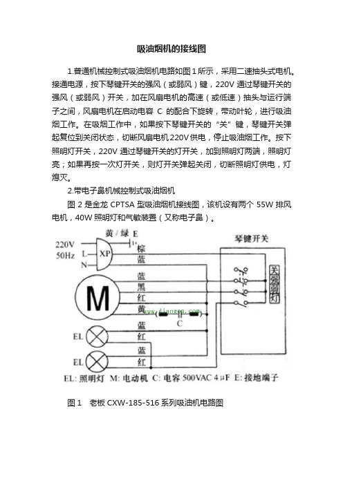
吸油烟机的接线图1.普通机械控制式吸油烟机电路如图1所示,采用二速抽头式电机。
接通电源,按下琴键开关的强风(或弱风)键,220V通过琴键开关的强风(或弱风)开关,加在风扇电机的高速(或低速)抽头与运行端子之间,风扇电机在启动电容C的配合下旋转,带动叶轮,进行吸油烟工作。
在吸烟工作中,如果按下琴键开关的“关”键,琴键开关弹起复位到关闭状态,切断风扇电机220V供电,停止吸油烟工作。
按下照明灯开关,220V通过琴键开关的灯开关,加到照明灯两端,照明灯亮;如果再按一次灯开关,则灯开关弹起关闭,切断照明灯供电,灯熄灭。
2.带电子鼻机械控制式吸油烟机图2是金龙CPTSA型吸油烟机接线图,该机设有两个55W排风电机,40W照明灯和气敏装置(又称电子鼻)。
图1 老板CXW-185-516系列吸油机电路图图2 金龙CPTSA型吸油烟机接线图(l)照明灯控制在开关K4和停止开关闭合时,220V电源电压就可加到照明两端,照明灯亮。
再按开关K4,则该开关复位到断开状态,切断照明灯220V供电,照明灯熄灭。
(2)左/右风扇手动控制按下左/右风扇开关K2、K3,220V电源电压通过这两个开关、气敏装置上的继电器J常闭触点、停止开关K5常闭触点,加到左/右风扇电机Ml、M2两端,在1.2VF的启动电容的配合下,左/右风扇电机运转进行吸油烟工作。
在吸油烟工作期间,如果按下开关K2(或K3时),则该开关弹起,复位到断开状态,切断风扇电机M1(或M2)的220V供电,风扇电机M1(或M2)停止运转。
在吸油烟工作期间,如果按下停止开关K5,则切220V供电,风扇电机、照明灯、气敏装置等220V供电,整机停止工作。
3.气敏自动控制气敏装置内部电路如图3所示,继电器J触点为常闭;QM是气敏管,接触可燃气体时电阻下降(气体浓度越高阻值越小);运算器IC2(Al、A2、A3、A4)负责气敏检测及控制,IC3(KD-9561)负责气敏报警控制。