完整版无线传感器网络仿真软件用户手册
传感器仿真软件使用说明书

传感器仿真软件使用说明书The Standardization Office was revised on the afternoon of December13, 2020THSRZ-2型传感器系统综合实验装置仿真软件使用说明书THSRZ-2型传感器系统综合实验装置仿真软件 ................. 错误!未定义书签。
实验一属箔式应变片――单臂电桥性能实验。
................. 错误!未定义书签。
实验二金属箔式应变片――半桥性能实验 ......................... 错误!未定义书签。
实验三金属箔式应变片――全桥性能实验 ......................... 错误!未定义书签。
实验四直流全桥的应用――电子秤实验 ............................. 错误!未定义书签。
实验五交流全桥的应用――振动测量实验 ......................... 错误!未定义书签。
实验六扩散硅压阻压力传感器差压测量实验 ..................... 错误!未定义书签。
实验七差动变压器的性能实验 ............................................. 错误!未定义书签。
实验八动变压器零点残余电压补偿实验 ............................. 错误!未定义书签。
实验九励频率对差动变压器特性的影响实验 ..................... 错误!未定义书签。
实验十差动变压器的应用――振动测量实验 ..................... 错误!未定义书签。
实验十一电容式传感器的位移特性实验 ............................. 错误!未定义书签。
实验十二容传感器动态特性实验 ......................................... 错误!未定义书签。
GenOSV1.4无线传感器网络产品说明书

GenOS V1.4无线传感器网络产品说明书目录◆产品介绍: (3)◆产品展示: (3)◆技术特点: (4)◆应用领域: (4)◆产品参数: (4)◆包装组成: (5)◆系统构成: (6)◆处理器介绍: (6)◆供电特性: (6)◆电池使用与保养: (7)◆Linux系统软件安装: (8)◆Linux系统连接: (10)◆Linux系统使用: (12)◆Windows系统软件安装: (14)◆Windows系统连接: (17)◆Windows系统使用: (17)◆无线射频: (19)◆存储系统: (20)◆系统指示: (21)◆扩展接口: (21)◆温湿度传感器: (21)◆版本修订信息: (22)◆产品介绍:GenOS V1.4是一款完全符合IEEE802.15.4协议规范的、组合式的低功耗无线传感器网络模块,能够充分满足用户对于传感器网络的可靠、容错以及扩展和高级开发功能等要求,不仅仅适用于zigbee协议的研究和开发,同时也能够满足不同场合下对于系统设备的灵活要求。
GenOS V1.4具备了联机程序下载、脱机程序独立运行以及大容量存储等优秀的功能。
GenOS V1.X系列产品除在功能上兼具了UC Berkeley的Telosb系列无线开发节点的通讯和传输以及部分测试功能之外,在GenOS V1.2的基础上进行了大量的裁剪,使得其在体积上大大缩小,并且更适合于不同领域的裁剪和开发之用。
GenOS V1.4在V1.2的基础之上改善了供电性能、射频性能以及接口性能等功能。
GenOS V1.4无线传感器网络节点全面支持TinyOS2.1技术,具备USB程序烧录技术和JTAG程序烧录技术、单总线技术的ID芯片等Telosb以及其兼容产品具备特性、同时了保证系统的脱机独立运行,系统增加了锂电池供电电路以及对应的电源处理电路和USB充电电路。
◆产品展示:独立天线型GenOS V1.4无线传感器网络节点◆技术特点:●RF完全符合802.15.4规范,采用TI CC2420●最高可达250kbps的无线通讯速率●分离的模块形式,将核心板与底板完全分离●通过USB进行程序下载、数据通讯,同时可以通过JTAG下载程序●通过标准的USB打印电缆与计算机连接,方便组网●采用TI MSP430F14X或MSP430F16X系列超低功耗处理器,完整安装高达8MHz的高频率晶体振荡器和32768Hz的低频率时钟晶体振荡器●支持TinyOS2.0以及TinyOS2.1()●板载3个TinyOS标准的LED状态指示灯●板载1个TinyOS标准IO连接的用户独立独立按键●串行通讯扩展口、GPIO扩展口、AD和DA扩展接口●板载SHT11数字温度湿度传感器●板载锂离子电池(选配)和对应的电源供电和充电系统(选配)●板载1MB Flash存储芯片,支持Deluge T2◆应用领域:无线传感器网络实验与开发各类环境监测系统其他各类符合要求的应用场合◆产品参数:处理器TI MSP430F1611程序空间48K-BytesRAM 10K-Bytes工作频率8MHz模数转换器ADC 12位数模转换器DAC 12位串行通讯UART无线传输模块TI CC2420发射功率-24dbm ~ 0dbm(因模块有所不同)接受灵敏度-94dbm(因模块有所不同)发射频率 2.4GHz ~ 2.4835GHz通讯方式USB-RS232接口1组存储扩展1M-Byte Flash电源系统USB直接供电锂离子电池供电(选配)USB对锂离子电池充电(选配)接口扩展DAC输出1组ADC输入3组SVSIN、SVSOUT各1组PWM输出信号1组GPIO输出3组系统指示USB收发指示各1个LEDUSB供电指示1个LEDUSB对锂电池充电1个LED系统状态指示3个LED核心供电指示1个LED系统外形127mmL * 67mmW * 38mmH独立天线型依天线类型而定包装组成:每一套完整的GenOS V1.4包含以下组件1.GenOS V1.4 USB连接与通讯板、控制核心系统(已经组合好)2.高品质防干扰USB供电与通讯电缆一条3.GenOS V1.4无线传感器网络产品说明书一份4.TinyOS2.1系统软件Linux虚拟机镜像2套(命令行模式的debian系统)◆系统构成:GenOS V1.4相对于其他telosb兼容产品,增加了更多更适合用户扩展的功能,这里以框图的形式将系统各个部分的功能以及连接表示如下:◆处理器介绍:GenOS V1.4所采用的TI公司的MSP430F1611低功耗处理器具有16位的RISC体系结构,48KB的Flash、10KB的RAM以及其特有的256B的Flash Memory。
Crossbow 无线传感器网络快速上手指南
1 (烧写程序) 115200 8 None 1 None 00 00 00 4C -none- Port 0 10001
2 (数据通信) 57600 8 None 1 None 00 00 00 4C -none- Port 0 10002
3. MoteView 客户端程序演示;
需要的设备: 至少 2 个 Mote 节点(IRIS,MICAz 或 MICA2,本手册以 IRIS 为例) ; 至少 1 个传感器板(本手册以 MTS400 为例) ; 1 个 MIB520 网关(或其他 MIB 系列网关,手册只以 MIB520 示例) ; 安装了 MoteView 的 PC 机(软件安装请参考本手册第一节 MoteView 软件安装) ;
3.3 使用 MoteView 客户端程序查看无线传感器网络数据
点击 MoteView 面板“Connect to WSN” 按钮,选择 “Acquire Live Data”以获取实时数据;
4
Doc. # BJSC-0001 Rev. A
Crossbow 无线传感器网络快速上手指南
“Gateway”选项卡指定 MIB520 网关,端口号设为 COM(n+1),波特率为 57600;
选择”Application Name”为 XMTS400,点击”Done”即可获取传感器网络的实时数据。
Doc. # BJSC-0001 Rev. B
5
MoteView 的详细使用说明请参考 MoteView_User_Mannual,下载地址:
/Support/wUserManuals.aspx 提醒:Crossbow 还提供更多手册供用户下载: 了解 Tinyos 开发和 MoteWorks 开发环境入门, 请参考 MoteWorks Getting Started Guide; 了解 XMesh 组网和协议请参考 XMesh User's Manual; 了解 XMesh 数据包定义和解析请参考 XServe User's Manual; 了解 Mote 节点和 MIB 网关详细信息请参考 MPR-MIB Wireless Module User's Manual; 了解传感器板和数据采集板详细资料请参考 MTS/MDA Sensor Board User's Manual; 国内手册下载地址: /%E8%B5%84%E6%BA%90%E4%B8%8B%E8%BD%BD/% E4%BA%A7%E5%93%81%E6%89%8B%E5%86%8C/tabid/80/Default.aspx
无线传感器网络实验手册cygwin

XLUC目录实验一开发环境搭建实验 (2)实验二程序烧录实验 (10)实验三硬件接口实验 (13)实验四 ADC采样实验 (19)实验五串口通讯实验 (24)实验六点对点射频实验 (32)实验七传感器添加实验 (39)实验八基于网关板的pc机数据采集和分析实验 (48)实验九基于sink节点数据采集和分析实验 (57)实验十基于web的数据录入和数据访问实验 (61)实验一开发环境搭建实验以下步骤描述了如何逐步搭建无线传感器网络实验开发环境注:本开发环境是在Windows XP操作系统下搭建的先决条件:∙AtoseNet环境:Cygwin atos4tinyos.msi安装包,在光盘的路径为,无线传感器网络1.5\TinyOS2\TinyOS_install\atos4tinyos.msi 。
∙Keil C51编译器安装包:c51v808a.exe,在光盘的路径为,无线传感器网络1.5\TinyOS2\TinyOS_install\c51v808a.exe 。
∙IIS服务器:准备一张Windows XP professional 的安装光盘。
∙SQL SERVER 2005数据库管理工具:准备一张SQL SERVER 2005的安装光盘。
创建AtoseNet环境:Cygwin1.打开无线传感器网络光盘,进入如下路径\TinyOS2\TinyOS_install\, 双击atos4tinyos.msi 进入安装过程2.进入如下界3.单机下一步4.选择合适的路径(这里选择缺省路径),点击“下一步”5.单击安装,进入安装进程如下6.安装完成后将出现如下两个界面7.选择完路径后单击“点击开始安装”8.进入Cygwin安装界面,安装完成后自动弹出如下界面:9.请任意键后即可完成安装。
桌面上会自动建立Cygwin的快捷方式,单击进入即可安装Keil C51 编译器10.打开无线传感器网络光盘,进入如下路径\TinyOS2\TinyOS_install\, 双击c51v808a.exe 进入安装过程11.单击“Next”并且选中“I agree to all the terms of the preceding LicenseAgreement”12.选择默认的路径13.选择安装路径后,单击“Next”:14.输入用户名等资料后单击“Next”进入安装进度界面:15.单击“Finish”完成安装过程。
M5600 U5600 无线压力传感器软件手册说明书
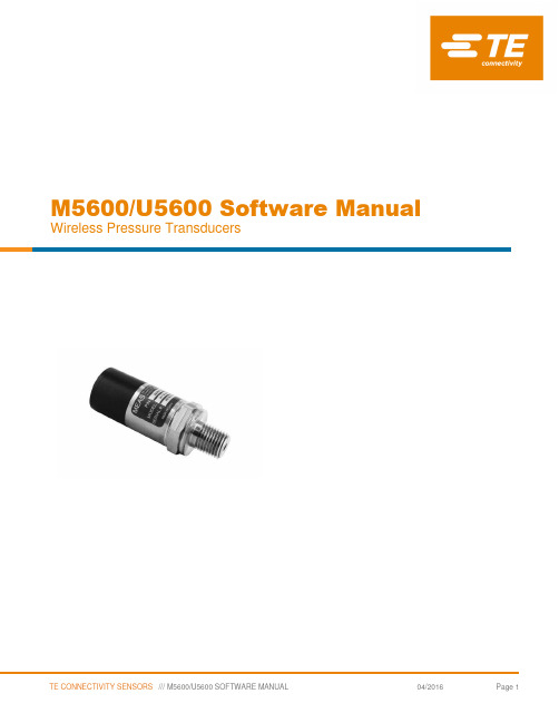
M5600/U5600 Software Manual Wireless Pressure TransducersContents1 Introduction Description 32 Manual Smartphone/Tablet Software Installation and Operation Manual 33 Manual Windows Version Software Installation and Operation Manual 44 Protocol Software Protocol Specification 161 IntroductionThe M5600 and U5600 pressure transducers use standard 2.4GHz wireless communication tag. The long battery life and integration design make these transducers a perfect fit for many industrial and commercial applications including marine, residential, campers, water, hydraulic, irrigation, pool, medical and sprinkler systems, or anywhere you would need to monitor pressure without the need for wires.By installing the Windows® version software on your PC or embedding the wireless signal in your integrated system, you can monitor pressure and temperature in real time.2 Smartphone/Tablet Software Installation1. Download and install the “TE Sensor Tag” app for iOS or Android™ from the Apple App Store or Google Play Store.2. Install the battery into the transducer.3. Turn on standard 2.4GHz wireless communication tag for smartphone/tablet.4. Run “TE Sensor Tag” app on smartphone/tablet and it will start searching for the transducer.5. Select the transducer (M5600 or U5600) found by the app to pair it to your smartphone/tablet.6. Once paired, the pressure and temperature charting will begin automatically. Data is collected every 5 seconds (programmed for bestbattery life).3 Windows Version Software Installation and Operation Manual Hardware & System Requirement∙PC with USB serial port support∙USB Dongle: BT900-US∙Operation system: Windows XP, Windows 7 or above∙Microsoft .NET Framework4.0 or aboveDongle Installation and Programming1. Insert the USB Dongle (BT900-US) into the USB socket of the PC.The PC will install the related USB drivers automatically.2. After installing FT232R USB UART, open the PC’s Device Manager and check if the USB Dongle has the port number assigned asbelow (COM5 in this example):If not assigned, then it is necessary to install the FTDI FT232 USB Serial Converter Driver following instructions from the below link: https:///tutorials/how-to-install-ftdi-drivers/windows---in-depthVerify COM port is assigned to the Dongle in the Device Manager before proceeding to the next step.3. Copy Window’s client software “TESS-M5600_U5600_Software.zip” to the PC and unzip it. Double-click to run UwTerminal in folder:TESS 5600\UwTerminal\. User interface should display as below:4. Click “Accept” to enter the configuration interface. Select the proper COM port where the Dongle is installed and leave the others atdefault settings.Then click “OK” to enter the command-line interface:5. Input “at &F *” (at space &F space *) and press “Enter”. The screen will display “ FFS Erased, Rebooting…”Close the window by clicking the “X” at the upper right corner.6. Run “BT900UartFwUpgrade.exe” in folder: TESS 5600\BT900_9.1.10.3 to update the firmware. Follow these steps: Press “OK” →specify the correct COM port →press “OK” → press “Start Upgrade” → let it run until finish →pressing “Quit.”7. Remove the USB Dongle and re-insert, repeat above steps 3 & 4.Input “at I 3” and press “Enter,” displaying “9.1.10.3” which is the latest version of the firmware.Input “at &F *” and press “Enter.” Screen will display “FFS Erased, Rebooting…”Input “at+dir” and press “Enter.”8. Right-click inside the window and click “load precompiled BASIC”After the “Open” window pops up, select “smartZ.umc” in folder “TESS 5600\” and press “Open”Text will scroll and after 1-2 minutes, it will display “DONE.”Close the “UwTerminal” window. Remove the USB Dongle and re-insert.Monitoring Software Operation Manual1. Double-click to run TESS 5600 for Windows in folder: TESS 5600\source\bin\Release\. The client software user interface shoulddisplay as below. Certain explanations can be found when moving the cursor onto the words.More explanations are provided as below:2. Ensure the Port Name matches the COM number in the Device Manager. Click the “Start” button, and then a “Scan” window will popup to search for available wireless devices. Double-click the MAC number matching the target device to select it.3. The software will start receiving and recording data on battery level and real-time pressure and temperature.Clicking the “Stop” button will stop the data taking process.4. When “Data Logging” is enabled and the interval set, a “Save“ window will pop up. When clicking the “S tart” button, all data will besaved in the folder appointed by the user (default: \\TESS\\data\\) as a *.dat file which can be opened with MS Excel.The “Date Time“ column can be formatted to display seconds as shown below:4 Software Protocol SpecificationUUID for the M5600/U5600 is available, which allows the user to compile their own program to recognize the sensor’s wireless signal and detect pressure, temperature and battery capacity.T is a 16 bits signed word, equals 0x7FFF if erroneous.P, Pmin and Pmax are 32 bits signed words, equal 0x7FFFFFFF if erroneous.T is a temperature value with 0.01°C resolution.P, Pmin and Pmax are pressure values with 0.1Pa resolutionCONVERSIONTemperature (°C) = T / 100Pressure (Pa) = P / 10Pressure (Psi) = P / 10 / 6894.7Battery Service:0% to 100% represents a supply voltage from 2.0V to 3.0V with 1%/bit resolution. STATUSNORTH AMERICA EUROPE ASIAMeasurement Specialties, Inc., a TE Connectivity company 45738 Northport Loop West Fremont, CA 94538Tel: +1 800 767 1888Fax: +1 510 498 1578************************MEAS France SAS,a TE Connectivity company26 Rue des Dames78340 Les Clayes-sous-Bois, FranceTel: +33 (0) 130 79 33 00Fax: +33 (0) 134 81 03 59************************Measurement Specialties (China) Ltd.,a TE Connectivity companyNo. 26 Langshan RoadShenzhen High-Tech Park (North) Nanshan District,Shenzhen, 518057ChinaTel: +86 755 3330 5088Fax: +86 755 3330 5099************************/sensorsolutionsAndroid is a trademark of Google Inc.Google Play is a trademark of Google Inc.iOS is a trademark or registered trademark of Cisco in the U.S. and other countries and is used under license.Microsoft, Encarta, MSN, and Windows are either registered trademarks or trademarks of Microsoft Corporation in the United States and/or other countries.Android and Windows are trademarks of their respective owners.The Bluetooth® word mark and logos are registered trademarks owned by the Bluetooth SIG, Inc. and any use of such marks by TE Connectivity is under license. Other trademarks and trade names are those of their respective owners.Measurement Specialties Inc., a TE Connectivity company.Measurement Specialties (MEAS), American Sensor Technologies (AST), TE Connectivity, TE Connectivity (logo) and EVERY CONNECTION COUNTS are trademarks. All other logos, products and/or company names referred to herein might be trademarks of their respective owners.The information given herein, including drawings, illustrations and schematics which are intended for illustration purposes only, is believed to be reliable. However, TE Connectivity makes no warranties as to its accuracy or completeness and disclaims any liability in connection with its use. TE Connectivity‘s obligations shall only be as set forth in TE Connectivity‘s Standard Terms and Conditions of Sale for this product and in no case will TE Connectivity be liable for any incidental, indirect or consequential damages arising out of the sale, resale, use or misuse of the product. Users of TE Connectivity products should make their own evaluation to determine the suitability of each such product for the specific application.© 2016 TE Connectivity Ltd. family of companies All Rights Reserved.Rev 02016/04/05。
IWPT系列无线温度传感器操作手册说明书

|IWPT SeriesINDUSTRIAL WIRELESS PRESSURE TRANSMITTERWhilst every effort has been taken to ensure the accuracy of this document, we accept no responsibility for damage, injury, loss, or expense resulting from errors or omissions, and reserve the right of amendment without notice.Information for usersThis equipment has been tested and found to comply with the limits for a Class B device, pursuant to part 15 of the FCC Rules. These limits are designed to provide reasonable protection against harmful interference in a residential installation. This equipment generates uses and can radiate radio frequency energy, and if not installed and used in accordance with the instructions, may cause harmful interference to radio communications. However, there is no guarantee that interference will not occur in a particular installation. If this equipment does cause harmful interference to radio or television reception, which can be determined by turning the equipment off and on, the user is encouraged to try to correct the interference by one or more of the following measures:•Reorient or relocate the receiving antenna•Increase the separation between the equipment and receiver•Connect the equipment into an outlet on a circuit different from that which the receiver is connected•Consult the dealer or an experienced radio/TV technician for helpCaution: To satisfy FCC RF Exposure requirements for mobile and base station transmission devices, a separation distance of 20cm or more should be maintained between the antenna of this device and persons during operation. To ensure compliance operation at closer than this distance is not recommended. The antenna used for this transmitter must not be co-located or operating in conjunction with any other antenna or transmitter. No other antenna may be used with this equipment other than the PCB antenna supplied with this equipment.This document may not be reproduced in any way without the prior written permission of the company.Cynergy3 Components Ltd7 Cobham Road, Ferndown Industrial Estate, WimborneDorset BH21 7PE, United KingdomTel:+44(0)1202897969,email:******************CONTENTS1.INTRODUCTION _______________________________________________________ 21.1 SAFETY INFORMATION _____________________________________________________ 21.2HARDWARE FEATURES ____________________________________________________ 22.UNPACKING__________________________________________________________ 33.PRODUCT IDENTIFICATION LABEL _____________________________________ 35.SETTING UP THE IWPT WIRELESS PRESSURE TRANSMITTER ___________ 46.TROUBLE-SHOOTING GUIDE__________________________________________ 67.SYSTEM PART NUMBERS______________________________________________ 78.SPECIFICATIONS & CERTIFICATIONS__________________________________ 9 1. INTRODUCTION1.1 Safety InformationThis manual contains information that must be observed in the interest of your safety and to avoid damage to assets. Please read this manual before installing and commissioning the device and keep the manual in an accessible location for all users.Contains FCC ID: W70MRF24J40MDMECaution: To satisfy FCC RF Exposure requirements for mobile and base station transmission devices, a separation distance of 20cm or more should be maintained between the antenna of this device and persons during operation. To ensure compliance operation at closer than this distance is not recommended. The antenna used for this transmitter must not be co-located or operating in conjunction with any other antenna or transmitter. No other antenna may be used with this equipment other than the PCB antenna supplied with this equipment.Please see the Certifications section for more information on RF Exposure Compliance 1.2 Hardware FeaturesThe IWPT range of Wireless Pressure Transmitters has been designed to measure the pressure of the medium connected and transmit the value to one of the IWR range of receivers where the value can be outputted as either a 4-20 mA or 1-5 V dc signal.The IWR-1 has a single output and the IWR-5 has five outputs, each of which can be linked to an IWPT transmitter. The IWPT pressure transmitter works on the license-free 2.4 GHz band.Ranges of up to 500 m are possible using the standard transmitter and receiver unit with the optional 3dBi antenna giving a range of up to 750 m. The transmitter is powered by a 3.6V lithium cell and care must be taken to insert the battery in the correct polarity.2. UNPACKINGThe instrument should be carefully inspected for signs of damage that may have occurred in transit. In the unlikely case that damage has been sustained, DO NOT use the instrument, but please retain all packaging for our inspection and contact your supplier immediately.3. PRODUCT IDENTIFICATION LABELThe unit delivered should be carefully inspected to ensure it is suitable for the application required. Detailed information on the product is included in the identification label and the user manual.Please ensure in particular, that the pressure range of the IWPT is suitable for the intended application and that the IWPT unit will not be subjected to pressures and/or temperatures greater than those specified in this manual.4.INSTALLING/CHANGING THE BATTERYA Lithium 3.6V battery is included inside the IWPT transmitter. The battery may be changed at any time but the correct polarity must be observed at all times! After the battery has been changed, the pushbutton SW1 should be pushed for 5s at the same time as the unit is switched on using SW3. This is to ensure the battery life count is set correctly when a new battery is installed.The internal LED will flash 5 times to indicate this procedure has been carried out successfully.The battery life is determined by the rate the transmitter sends the Pressure value to the receiver, this update rate can be selected using Dip Switch 1 and the default value is 10s. Please dispose of all batteries as specified by the legislator according to the Closed Substance Cycle and Waste Management Act or country regulations.! ! WARNING !MAKE SURE THE CORRECT BATTERY POLARITY IS OBSERVED!!! WARNING !INCORRECT BATTERIES MAY DAMAGE THE UNIT USE ONLY 3.6V LITHIUM C CELL BATTERIES5.1 Mounting InstructionsEnsure that:-- The instrument is used on a pressure medium that is compatible with the wetted parts- The correct seal is used and that the maximum torque (see below) is not exceeded- Fluid is not allowed to freeze in the pressure port as the diaphragm may be ruptured- No sharp objects are inserted into the pressure port as the diaphragm may be damagedTighten the unit in place using a wrench on the 18mm A/F hexagon provided on the unit. Ensure that no more than 15Nm is applied, that the system is de-pressurized, and that a suitable pressure seal is used.5.2 SETTING UP THE IWPT WIRELESS PRESSURE TRANSMITTERThe IWPT instrument is shipped in a default configuration which allows the unit to connect with any default IWR receiver unit and transmit the measured pressure every 10s simply by switching the unit on using SW3 on the internal circuit board.If a different update rate is required, or a different network frequency channel is required these parameters can be selected using DIP Switch 1 as detailed below:Switches 1, 2, 3 & 4 select the RF Network the IWPT will transmit on. The default network for both the IWPT transmitter and IWR receiver is network 1. RF NETWORK 1 2 3 4 1 0 0 0 0 2 0 0 0 1 3 0 0 1 0 4 0 0 1 1 5 0 1 0 0 6 0 1 0 1 7 0 1 1 0 8 0 1 1 1DIP SWITCHLED1BATTERYON/OFF Switch SW3SW1USB+9 1 0 0 010 1 0 0 111 1 0 1 012 1 0 1 113 1 1 0 014 1 1 0 115 1 1 1 016 1 1 1 1Switches 5, 6 & 7 select the Transmission rate of the unit. This effectively sets how often the pressure value is sent to the receiver.Transmit time 5 6 710 seconds 0 0 020 seconds 0 0 130 seconds 0 1 060 seconds 0 1 1120 seconds 1 0 0600 seconds 1 0 11 second 1 1 05 seconds 1 1 1Switches 8, 9, and 10 set the Channel Number of the transmitter. This is used with the 5 channel receiver unit (IWR-5) to select which Pressure transmitter is linked to which4-20 mA or 1-5 V dc output channel.Tx Channel Number 8 9 101 0 0 02 0 0 13 0 1 04 0 1 15 1 0 0The IWPT transmitter is now set up and ready to be used. Install the unit into the pipework as required and switch the unit ON using SW3. Pushbutton switch SW1 can be pushed to force the unit to transmit its current pressure and LED 1 will flash twice if the transmission has been received and acknowledged by an IWR receiver unit.If the unit has transmitted successfully the 4-20 mA or 1-5 V dc output of the connected receiver unit will output a value reflecting the pressure level being measured.6.TROUBLE-SHOOTING GUIDEProblem encountered Possible CausesLED1 doesn’t flash when push button SW1 is pressed Unit not switched on, switch on using SW3. The battery is not installed correctly.The battery needs replacing.LED1 only flashes once when SW1 is pressed IWR receiver not switched on. IWR receiver is not set up for the same RFnetwork.IWR receiver not within range of the transmitter.If an IWR-1 receiver is used, ensure that the transmitter is set to Tx Channel 1Output from the IWR receiver isn’t equivalent to the Pressure being monitored IWR receiver set up incorrectly, see IWR user manual for further details.Check that the green external LED on the receiver is flashing when the transmitter push button is pressed as the receiver may be out of range.7. SYSTEM PART NUMBERSPart Number Pressure Range Receiver Output IWPT-G1000-00 0-1 Bar g 4-20 mA or 1-5 V dc IWPT-G6000-00 0-6 Bar g 4-20 mA or 1-5 V dc IWPT-GM1P9-00 -1-+9 Bar g 4-20 mA or 1-5 V dc IWPT-G1002-00 0-10 Bar g 4-20 mA or 1-5 V dc IWPT-G1602-00 0-16 Bar g 4-20 mA or 1-5 V dc IWPT-CO184-00 -1-+24 Bar g 4-20 mA or 1-5 V dc IWPT-G2502-00 0-25 Bar g 4-20 mA or 1-5 V dc IWPT-G4002-00 0-40 Bar g 4-20 mA or 1-5 V dc IWPT-G1003-00 0-100 Bar g 4-20 mA or 1-5 V dc IWPT-G2503-00 0-250 Bar g 4-20 mA or 1-5 V dc IWPT-G4003-00 0-400 Bar g 4-20 mA or 1-5 V dc IWPTU-GP015-00 0-15 psi g 4-20 mA or 1-5 V dc IWPTU-GP030-00 0-30 psi g4-20 mA or 1-5 V dc IWPTU-CO446-00 -14.5 to +150 psi g4-20 mA or 1-5 V dc IWPTU-GP075-00 0-75 psi g4-20 mA or 1-5 V dc IWPTU-GP100-00 0-100 psi g4-20 mA or 1-5 V dc IWPTU-CO447-00 -14.5 to +350 psi g4-20 mA or 1-5 V dc IWPTU-GP150-00 0-150 psi g4-20 mA or 1-5 V dc IWPTU-GP300-00 0-300 psi g4-20 mA or 1-5 V dc IWPTU-GP750-00 0-750 psi g4-20 mA or 1-5 V dc IWPTU-GP1K5-00 0-1500 psi g4-20 mA or 1-5 V dc IWPTU-GP3K6-00 0-3600 psi g4-20 mA or 1-5 V dc IWPTU-GP5K8-00 0-5800 psi g4-20 mA or 1-5 V dc IWPTL-G0050-00 0-50 mbar g 4-20 mA or 1-5 V dc IWPTL-G0100-00 0-100 mbar g 4-20 mA or 1-5 V dc IWPTL-G0250-00 0-250 mbar g 4-20 mA or 1-5 V dc IWPTL-G0500-00 0-500 mbar g 4-20 mA or 1-5 V dc IWPTL-G0750-00 0-750 mbar g 4-20 mA or 1-5 V dc IWPTL-G1000-00 0-1000 mbar g 4-20 mA or 1-5 V dc IWPTL-A0500-00 0-500 mbar abs 4-20 mA or 1-5 V dc IWPTL-A0750-00 0-750 mbar abs 4-20 mA or 1-5 V dc IWPTL-A1000-00 0-1000 mbar abs 4-20 mA or 1-5 V dcPart Number Pressure Range Receiver Output IWPTLU-GP001-00 0-1 psi g 4-20 mA or 1-5 V dc IWPTLU-GP002-00 0-2 psi g 4-20 mA or 1-5 V dc IWPTLU-GP005-00 0-5 psi g 4-20 mA or 1-5 V dc IWPTLU-GP008-00 0-8 psi g 4-20 mA or 1-5 V dc IWPTLU-GP010-00 0-10 psi g 4-20 mA or 1-5 V dc IWPTLU-GP015-00 0-15 psi g 4-20 mA or 1-5 V dc IWPTLU-AP005-00 0-5 psi abs 4-20 mA or 1-5 V dc IWPTLU-AP010-00 0-10 psi g 4-20 mA or 1-5 V dc IWPTLU-AP015-00 0-15 psi g 4-20 mA or 1-5 V dcPart Number Number of Output ChannelsIWR-1 OneIWR-5 FiveIANT-3 3 dBi Antenna IWPT-SA Swivel Adaptor (1/4” BSP)8.SPECIFICATIONS & CERTIFICATIONSUnited States FCCThis equipment has been tested and found to comply with the limits for a Class B device, pursuant to part 15 of the FCC Rules. These limits are designed to provide reasonable protection against harmful interference in a residential installation. This equipment generates, uses, and can radiate radio frequency energy, and if not installed and used in accordance with the instructions, may cause harmful interference to radio communications. However, there is no guarantee that interference will not occur in a particular installation. If this equipment does cause harmful interference to radio or television reception, which can be determined by turning the equipment off and on, the user is encouraged to try to correct the interference by one or more of the following measures:• Reorient or relocate the receiving antenna• Increase the separation between the equipment and receiver• Connect the equipment into an outlet on a circuit different from that which the receiver is connected • Consult the dealer or an experienced radio/TV technician for helpWarning: Changes or modifications not expressly approved by Cynergy3 could void the user’s authority to operate the equipment.RF ExposureContains FCC ID: W70MRF24J40MDMEIn this equipment, the antenna supplied is a PCB antenna and an alternative antenna must not be used.System PerformanceAccuracy (non-linearity & hysteresis <±0.25% / FS (BFSL)Setting ErrorsZero & Full Scale,<±0.5% / FS Thermal Zero Shift <±0.04% / FS / °C Thermal Span Shift <±0.02% / °C typicalMedia Temperature -20 to +135 °C Ambient Temperature -20 to +50 °C Storage Temperature -20 to +80 °CPressure Housing 303 Stainless Steel O Ring Seals Viton DiaphragmCeramic Enclosure Material Acetal Weight310 gRF TransmitterContains FCC W70MRF24J40MDME Power Requirements Lithium Ion C 3.6V CellBattery Life 5 Years (10s transmission rate)Dimensions 132mm x 79mm x 52mm (L x W x D) Mounting Any OrientationSensata Technologies, Inc. (“Sensata”) data sheets are solely intended to assist designers (“Buyers”) who are developing systems that incorporate Sensata products (also referred to herein as “components”). Buyer understands and agrees that Buyer remains responsible for using its independent analysis, evaluation and judgment in designing Buyer’s systems and products. Sensata data sheets have been created using standard laboratory conditions and engineering practices. Sensata has not conducted any testing other than that specifically described in the published documentation for a particular data sheet. Sensata may make corrections, enhancements, improvements and other changes to its data sheets or components without notice.Buyers are authorized to use Sensata data sheets with the Sensata component(s) identified in each particular data sheet. HOWEVER, NO OTHER LICENSE, EXPRESS OR IMPLIED, BY ESTOPPEL OR OTHERWISE TO ANY OTHER SENSATA INTELLECTUAL PROPERTY RIGHT, AND NO LICENSE TO ANY THIRD PARTY TECHNOLOGY OR INTELLECTUAL PROPERTY RIGHT, IS GRANTED HEREIN. SENSATA DATA SHEETS ARE PROVIDED “AS IS”. SENSATA MAKES NO WARRANTIES OR REPRESENTATIONS WITH REGARD TO THE DATA SHEETS OR USE OF THE DATA SHEETS, EXPRESS, IMPLIED OR STATUTORY, INCLUDING ACCURACY OR COMPLETENESS. SENSATA DISCLAIMS ANY WARRANTY OF TITLE AND ANY IMPLIED WARRANTIES OF MERCHANTABILITY, FITNESS FOR A PARTICULAR PURPOSE, QUIET ENJOYMENT, QUIET POSSESSION, AND NON-INFRINGEMENT OF ANY THIRD PARTY INTELLECTUAL PROPERTY RIGHTS WITH REGARDTO SENSATA DATA SHEETS OR USE THEREOF.All products are sold subject to Sensata’s terms and conditions of sale supplied at SENSATA ASSUMES NO LIABILITY FOR APPLICATIONS ASSISTANCE OR THE DESIGN OF BUYERS’ PRODUCTS. BUYER ACKNOWLEDGES AND AGREES THAT IT IS SOLELY RESPONSIBLE FOR COMPLIANCE WITH ALL LEGAL, REGULATORY AND SAFETY-RELATED REQUIREMENTS CONCERNING ITS PRODUCTS, AND ANY USE OF SENSATA COMPONENTS IN ITS APPLICATIONS, NOTWITHSTANDING ANY APPLICATIONS-RELATED INFORMATION OR CONTACT US EUROPE+44 (0)1202 897969********************* Cynergy3 Components Ltd.7 Cobham Road, Ferndown Industrial Estate, Wimborne, Dorset,BH21 7PE, United Kingdom USACaution: To satisfy FCC RF Exposure requirements for mobile and base station transmission devices, a separation distance of 20cm or more should be maintained between the antenna of this device and persons during operation. To ensure compliance operation at closer than this distance is not recommended. The antenna used for this transmitter must not be co-located or operating in conjunction with any other antenna or transmitter. No other antenna may be used with this equipment other than the PCB antenna supplied with this equipment.Canada (IC)EnglishThis device complies with Industry Canada license-exempt RSS standard(s). Operation is subject to the following two conditions: (1) this device may not cause interference, and (2) this device must accept any interference, including interference that may cause undesired operation of the device.Under Industry Canada regulations, this radio transmitter may only operate using an antenna of the type and maximum (or lesser) gain approved for the transmitter by Industry Canada. To reduce potential radio interference to other users, the antenna type and its gain should be so chosen that the equivalent isotropically radiated power (e.i.r.p.) is not more than that necessary for successful communication. FrenchLe présent appareil est conforme aux CNR d’industrie Canada applicables aux appareils radio exempts de licence. L’explitation est autorisée aux deux conditions suivantes: (1) l’appareil ne doit pas produire de brouillage, et (2) l’utilisateur de l’appareil doit accepter tout brouillage, et (2) l’utilisateur de l’appareil doit accepter tout brouillage radioelectrique subi, même si le brouillage est susceptible d’en compromettre le fonctionnement.Conformément à la réglementation d’Industrie Canada, le présent émetteur radio peut fonctionner avec une antenna d’un type et d’un gain maximal (ou inférieur) approuvé pour l’émetteur par Industrie Canada. Dans le but de réduire les risques de brouillage radioélectrique à I’intention des autres utilisateurs, il fait choisir le type d’antenne et son gain de sorte que la puissance isotrope rayonnée équivalente (p.i.r.e) ne dépasse pas l’intensité nécessaire à l’établissement d’une communication satisfaisante.EuropeThe MRF24J40MD/ME wireless module used in this equipment has been tested to R&TTE Directive 1995/5/EC Essential Requirements for Health and Safety (Article 3.1(a)), Electromagnetic Compatibility (EMC) Article 3.1(b)) and Radio (Article 3.2) and are summarized in the table below. A Notified Body Opinion has also been issued for this module.Certification Standards ArticleSafety EN60950-2006+A11+A1:2010 (3.1(a))Health EN50371:2002-03 (3.1(a))EMC EN301 489-1 V1..8.1 (2008-04_ (3.1(b))EMC EN301-489-17 V2.1.1(2009-05) (3.1(b))Radio EN 300 328 V1.7.1(2006-10) (3.2)。
RFbeam K-TS1 TSviewLite软件用户手册说明书

User Manual
Getting Started with TSviewLite
RFbeam TSviewLite is a graphical user interface (GUI) for our K-TS1 testsystem. TSviewLite presents a comfortable user interface and allows taking measures with just a few mouse clicks.
Target
The “Synthetic Target” simulates a moving object. RF signal received at "target Rx antenna" of K-TS1 will be amplified, SSB modulated by a sine wave and sent back via the "target Tx antenna". The radar transceiver will interpret this signal as a moving object and return a sine wave at its IF output. K-TS1 simulates “I and Q” components, that are producing 90° phase shifted IF signals at a stereo sensor. For K-TS1 modules with firmware V3.01 or higher you can also simulate the direction of the simulated target by changing the sign of the fTX control. A positive value will simulate a forward moving target and a negative value a backward moving target.
无线传感网络教学实验开发平台操

7> 8>
检查主板上的 ZigBee 模块是否接好。如果接好,模块的 LED 灯会闪烁。 选择 Zigbee 操作菜单的第二项,启动 ZigBee 网络。
启动 ZigBee 网络
9>
等待几秒钟之后,LCD 显示加载 ZigBee 网ful”)。 网关板上的 ZigBee 模块 LED 灯由闪烁状态变为常亮。 点击“exit”返回上一级菜单。
11)配置 PC 软件网络扫描相关参数 � 选配置“扫描网络拓扑的时间间隔周期”是多少秒,建议设定在 1-5 秒的范围内。 � 点击“开始扫描网络拓扑” ,开始扫描网络。
- 22 -
开始扫描网络拓扑
扫描网络拓扑的时间间隔周期
12)如果扫描到网络中有节点,显示如下图
13)等扫描大约十次以上之后,我们就可以点击“关闭扫描传感网络拓扑图”按钮,关闭 扫描。以便完成其它操作。
LED 向右方向, 做流水显示。
返回上一级菜 单
2.2 蜂鸣器实验
(略)
2.3 光照度采集实验
实验内容: 光照度测试实验。
实验步骤: 1> 选择“硬件测试”界面进入。 2> 选择“Light”按钮。 3> 进入光敏采集实验界面。
-5-
光敏显示区: 200 为采集到的 光敏传感器数据
返回上一级菜 单
我们在这个实验中,为了进一步测试,可以用手去盖一个光敏传感器,观察采集到的光 敏传感器数据会有什么变化。
2.4 高精度温湿度实验
实验内容: 温度和湿度采集实验。 实验步骤: 1> 选择“硬件测试”界面进入。 2> 选择“Temp Humidity”按钮。 3> 进入高精度温湿度实验界面。
-6-
湿度显示区: 45.9% 为 采 集 到 的 SHT10 传感器上湿度数 据
- 1、下载文档前请自行甄别文档内容的完整性,平台不提供额外的编辑、内容补充、找答案等附加服务。
- 2、"仅部分预览"的文档,不可在线预览部分如存在完整性等问题,可反馈申请退款(可完整预览的文档不适用该条件!)。
- 3、如文档侵犯您的权益,请联系客服反馈,我们会尽快为您处理(人工客服工作时间:9:00-18:30)。
无线传感器网络仿真软件用户手册2014年12月1日目录1. 简介 (1)1.1. 背景 (1)1.2. 软件运行环境 (1)1.3. 使用场景 (2)1.4. 试用版使用限制 (2)2. 安装 (2)2.1. 双击安装程序 (2)2.2. 安装向导 (3)2.3. 选择安装目录 (3)2.4. 选择是否建立开始菜单和创建快捷方式 (4)2.5. 安装 (4)2.6. 安装完成 (5)2.7. Atos-SensorSim快捷方式 (5)2.8. 安装目录中的文件夹 (7)2.9. Atos-SensorSim主界面 (7)3. Atos-SensorSim使用 (8)3.1. 网络管理 (8)3.1.1. 生成网络 (8)3.1.2. 查看生成网络的拓扑 (8)3.1.3. 修改生成网络的节点默认通信半径 (9)3.1.4. 显示网络节点属性 (9)3.1.5. 修改网络节点属性 (10)3.1.6. 增加网络节点 (10)3.1.7. 删除网络节点 (11)3.1.8. 网络显示缩放 (12)3.1.9. 保存生成的网络 (12)3.1.10. 打开保存的网络文件 (13)3.1.11. 创建网络文件分组 (13)3.1.12. 删除网络文件分组 (15)3.1.13. 删除网络文件 (16)3.2. 无线传感器网络算法管理 (18)3.2.1. 显示系统目前导入的算法 (18)3.2.2. 开始算法演示 (18)3.2.3. 停止算法演示 (19)3.2.4. 显示算法运行的节点分布 (20)3.2.5. 显示算法的网络链接信息 (20)3.2.6. 显示算法的网络链路质量信息 (21)3.2.7. 显示算法运行过程中经过的路线 (21)3.2.8. 显示算法的查询结果信息 (22)3.2.9. 调节算法演示的运行速度 (22)3.2.10. 单步执行算法 (23)3.2.11. 查看算法运行参数 (24)3.2.12. 查看算法运行过程中发生的事件 (24)3.2.13. 查看算法运行过程中发生事件的数据通信量 (25)3.2.14. 查看算法运行过程中发生事件的能量消耗 (25)3.2.15. 查看算法运行过程中的总能量消耗 (26)3.2.16. 快速查看算法运行过程 (26)3.2.17. 创建算法分组 (27)3.2.18. 删除算法分组 (29)3.2.19. 删除算法 (31)3.3. 无线传感器网络实验管理 (31)3.3.1. 显示系统中已保存的实验 (31)3.3.2. 查看实验 (32)3.3.3. 查看实验网络 (32)3.3.4. 查看实验算法 (33)3.3.5. 运行实验 (33)3.3.6. 创建实验分组 (34)3.3.7. 删除实验分组 (35)3.3.8. 删除实验 (37)无线传感器网络仿真软件用户手册1.简介1.1. 背景由于传感器网络及其算法的复杂性,传感器网络中的绝大多数算法的性能无法通过理论分析得到。
因此,通常采用在模拟器中模拟运行算法的方法以比较算法的性能,对无线传感器网络中的各种协议进行分析。
现有传感器网络模拟器集中于对网络层及其下层的模拟,而对包括数据收集、查询处理、拓扑控制、定位、时间同步、组网部署、路由协议等在内完整的模拟涉及较少。
比较著名的模拟器如NS2,Glomosim等均是网络底层协议模拟器,且不具备基于图形化用户界面的算法演示、调试、比较等功能。
为了解决上述问题,设计并实现了一新型传感器网络模拟器Atos-SensorSim以简化各类传感器网络算法的模拟实现,并提供API开发接口,基于Atos-SensorSim 实现新的传感器网络算法和协议。
除参数配置、网络拓扑生成、算法演示等基本功能外,该模拟器提取了现有的无线传感器网络算法和协议中所需的常用功能,并将其封装成组件以重用。
实现了算法演示组件Animator,对算法的详细执行过程进行图形化显示,以便快速发现算法实现的问题以及进行算法调试。
Atos-SensorSim具备算法分析功能,通过配置参数,可实现不同参数条件下的实验自动运行、实验结果统计和实验结果图自动生成。
Atos-SensorSim极大地降低了模拟算法实现的难度,为比较传感器网络算法的性能提供了一个快捷的平台。
1.2. 软件运行环境由于采用Java语言开发,模拟器具有跨平台性,可运行于主流的Window和linux 操作系统。
具体如下:(1)支持Windows XP、Windows 2000、Windows Vista、Windows7等主流Windows 操作系统。
(2)支持Centos、RedHat linux、Ubuntu等主流Linux操作系统;1无线传感器网络仿真软件用户手册1.3. 使用场景(1)教学该模拟器可在高校无线传感器网络、物联网相关课程教学过程中使用,为学生演示无线传感器网络Mac协议、路由协议、拓扑控制、时间同步、定位算法、链路估计算法、数据收集及查询、安全与隐私保护等经典无线传感器网络算法的基本原理、算法流程。
(2)科研该模拟器也可用于高校无线传感网络相关研究方向的高校教师进行算法设计、调试、测试和性能比较的仿真平台。
1.4. 试用版使用限制Atos-SensorSim试用版,不支持算法导入、用户自定义算法开发、实验配置、实验结果图自动生成等高级功能,且仅集成了部分无线传感器网络算法。
在Atos-SensorSim正式版中,上述高级功能及算法种类将不受限制。
2.安装2.1. 双击安装程序2无线传感器网络仿真软件用户手册2.2. 安装向导点击【下一步】,选择安装目录。
2.3. 选择安装目录选择安装目录后,点击【下一步】。
3无线传感器网络仿真软件用户手册2.4. 选择是否建立开始菜单和创建快捷方式点击【下一步】,进入安装过程。
2.5. 安装4无线传感器网络仿真软件用户手册2.6. 安装完成点击【完成】2.7. Atos-SensorSim快捷方式开始菜单出现Atos-SensorSim快捷方式5无线传感器网络仿真软件用户手册6无线传感器网络仿真软件用户手册2.8. 安装目录中的文件夹安装Atos-SensorSim后,安装目录中的文件夹如下所示:2.9. Atos-SensorSim主界面点击Atos-SensorSim.exe,进入Atos-SensorSim主界面从主界面可以看出,Atos-SensorSim有三项主要的功能:网络管理、算法管理和实验管理。
其中,网络管理主要用于配置、生成、显示和保存用于后续实验的不同网络。
算法管理用于配置、显示、导入各种无线传感器网络算法,包括数据收集、路由、查询处理、隐私保护、安全、定位、拓扑控制、时间同步等。
实验管理用于配置网络和算法参数,运行实验,得到实验结果。
7无线传感器网络仿真软件用户手册3.Atos-SensorSim使用3.1. 网络管理3.1.1.生成网络用户输入自定义的网络部署区域宽度、网络部署区域高度、网络节点数目、网络描述、节点默认通信半径后,点击【生成】按钮,生成网络。
3.1.2.查看生成网络的拓扑点击【生成的网络拓扑】,显示生成网络的拓扑连接情况。
8无线传感器网络仿真软件用户手册3.1.3.修改生成网络的节点默认通信半径在节点通信半径文本框中输入新的节点通信半径值,例如将其从50m修改为70米,网络拓扑随之发生变化。
3.1.4.显示网络节点属性单击网络中的某个节点,从而选中该节点。
选中该节后后,在主界面的右下角出现【选中节点属性】界面,该界面中显示了选中节点的属性信息。
9无线传感器网络仿真软件用户手册3.1.5.修改网络节点属性在【选中节点属性】界面中,可对选中节点的属性进行修改。
例如,将该节点的通信半径从默认值50修改为10,则该节点与周围的节点不连通。
3.1.6.增加网络节点在【生成的网络】或者【生成的网络拓扑】界面中,进行鼠标双击动作,;或者右击鼠标,在弹出菜单中选择创建节点,则在鼠标所在位置上生成一个新的节点。
10无线传感器网络仿真软件用户手册3.1.7.删除网络节点单击网络中的某个节点,从而选中该节点。
右击鼠标,在弹出菜单中选择删除节点,则删除选中的节点。
(1)删除前界面(2)删除后界面11无线传感器网络仿真软件用户手册3.1.8.网络显示缩放当网络较小时,可通过拖动【网络显示缩放】标尺,对显示的网络大小进行缩放。
3.1.9.保存生成的网络生成网络后,点击【网络】-【另存为】菜单,可将生成的网络保存为文件。
12无线传感器网络仿真软件用户手册3.1.10.打开保存的网络文件主界面右侧以.net结束的文件为用户保存的网络文件,双击该文件,则打开该文件保存的网络,以图形化界面的方式在右侧显示。
3.1.11.创建网络文件分组在主界面左侧【Networks】界面中,右击鼠标,在弹出的菜单中点击【创建分组】,可创建新的网络分组,从而将多个网络文件放到同一个分组中,方便管理。
13无线传感器网络仿真软件用户手册在弹出菜单中输入新的网络分组名:点击【OK】后,则在Test分组中建立了一个Test1分组。
如下图所示。
14无线传感器网络仿真软件用户手册3.1.12.删除网络文件分组在主界面左侧【Networks】界面中,右击鼠标,在弹出的菜单中点击【删除分组】,则删除鼠标指针所在的网络分组、其包含所有的网络文件、以及其子网络分组。
15无线传感器网络仿真软件用户手册3.1.13.删除网络文件在主界面左侧【Networks】界面中,选中要删除的网络文件,右击鼠标,在弹出的菜单中点击【删除分组】,则删除选中的网络文件。
16无线传感器网络仿真软件用户手册17无线传感器网络仿真软件用户手册3.2. 无线传感器网络算法管理3.2.1.显示系统目前导入的算法点击【算法】按钮,在主界面左侧,显示显示系统目前导入的算法。
包括数据收集、查询处理、路由、隐私等若干类算法。
3.2.2.开始算法演示双击某算法,在界面右侧显示出该算法的基本信息和执行Demo。
单击【运行】按钮,则算法从启动到结束的过程中,算法运行参数、发生的所有事件、节点消耗的能量、算法运行的总能耗,将显示在界面的右下角。
界面中心以动画的方式显示节点间的无线通信交互情况。
18无线传感器网络仿真软件用户手册3.2.3.停止算法演示点击【停止】按钮,停止算法运行演示。
19无线传感器网络仿真软件用户手册3.2.4.显示算法运行的节点分布点击界面中部的【网络】Tab页,显示算法运行的节点分布3.2.5.显示算法的网络链接信息点击界面中部的【链路】Tab页,显示算法运行的网络链接信息20无线传感器网络仿真软件用户手册3.2.6.显示算法的网络链路质量信息点击界面中部的【链路质量】Tab页,显示算法运行的网络链路质量信息3.2.7.显示算法运行过程中经过的路线点击界面中部的【路线】Tab页,显示算法运行过程中经过的路线。