
VSAM系列抗晃电保护器使用手册
VSAM系列抗晃电保护器使用手册
使用须知
尊敬的客户:
您好!
首先非常感谢您选用我公司的VSAM抗晃电保护器。
VSAM抗晃电保护器,能帮助贵公司解决因晃电而带来的烦恼,为企业的生产保驾护航。
为了确保产品的正确使用,请您按以下要求进行操作:
1.在使用产品前,请认真阅读本说明书。
2.当接线完毕后,应仔细检查接线是否正确以及是否松动。
3.接线和操作方法应严格按说明书进行。
4.请认真填写产品保修卡并妥善保管。
5.不要随意撕毁产品标识。
6.不得私自对产品进行拆卸。
一、产品概述
在我国大部分地区由于雷击、短路、故障重合闸、企业外部或内部电网故障、大型设备启动等原因,可能造成供电电压有效值快速下降至90%---10%,持续时间为10 ms 到5 s。
这种现象称为“电压跌落”又称“晃电”,接触器在晃电期间触头可能弹开,并引起相关连锁设备动作,导致生产线停车,造成巨大的经济损失。
晃电作为一种特殊故障,危害很大,特别是对连续性运行企业。
晃电就像毒瘤一般的影响着企业生产、产品质量、文件丢失及增加企业的资金流失。
晃电的危害很大,特别是对连续性运行生产的企业。
晃电因此也是各大企业,一直以来很大的困扰,同时也是各大企业生产线上非常重视和关注的严重问题。
由于晃电的严重危害性,市面上也出现了很多治理晃电问题的产品,但那些产品的弊端是显而易见的。
比如:接线复杂,操作复杂,对操作人员技术知识要求严格,抗晃电时间太短,局限性太多。
此外,需要对客户现场接触器(节能型、非节能型等)进行严格区分,还存在精准度不够,且每台设备只能带一个接触器等问题!
而我公司在治理晃电领域有着丰厚的现场经验,熟知客户需求。
经过多年经验积累,自主研发的VSAM抗晃电保护器。
该产品能有效的预防接触器因晃电时电压降低而引起的脱扣,让接触器在晃电时保持吸合,避开晃电时脱扣,保证设备的正常连续性运行。
我公司VSAM抗晃电保护器的优势在于。
接线方便,安装方便,操作简单,精准度高,抗晃电时间范围广,可用于任何种类的AC220V接触器,可同时保护多台接触器。
经过对产品无数次试验和优化。
现以广泛用于,石油,化工,冶金,矿山,电力,环保,市政,军工等领域。
也赢得了无数的客户好评反馈,着实有效的帮助客户解决因晃电带来的烦恼。
我们将以优质的产品性能,一流的售后服务。
竭诚为您的企业生产保驾护航。
二、技术优势
1.万能型
用户不需要区分原有接触器的类型(节能型、非节能型等),对控制线圈电压为交流220V的接触器,一律适用。
2.抗晃电时间设定范围宽
根据用户的不同要求,0.1秒~ 9.9秒可设定。
3.无延时
正常启动或者停止不会出现延时。
4.超级电容储能
采用超级电容,用作晃电时模块的后备电源,具有充电时间短、放电电流大、循环充放电次数多、无记忆效应、充电控制电路简单等优点。
5.单片机控制
采用单片机控制,具有精、准、稳特点。
能够正确区别晃电和正常断电。
三、功能设置
1.用户根据自身需要设置延时时间0.1秒~ 9.9秒,时间步长为0.1秒。
2.VSAM抗晃电保护器充电时间为1分钟,接入市电AC220V抗晃电模块自
动开机,5S后处于就绪状态,VSAM抗晃电保护器开始工作,运行灯(绿灯)常亮。
3.在运行状态下,当市电AC220V中断5min后仍没有恢复,VSAM抗晃电保
护器停止并关机。
4.在晃电发生时,接触器不脱扣,有效抵抗晃电。
5.在VSAM抗晃电保护器发生故障时,抗晃电保护器报警,红色报警灯闪烁。
6.当VSAM抗晃电模块内部发生故障时,会自动并无间隔的切换到旁路功能
(如果切换时负载接触器处于合闸状态,保证接触器不脱扣),此时旁路指示灯常亮(黄灯),保证客户正常生产和使用。
四、工作参数
1. 工作电压:AC220V +15%~-20%
2. 使用环境温度:-20℃~ +60℃
3. 抗晃电时间范围:0.1秒~ 9.9秒
4. 时间调整步长:0.1秒
5. 适用范围:所有线圈电压AC220V的交流接触器。
注意:本产品不能用于直流接触器
五、 接线说明
VSAM 抗晃电保护器的接线如下所示:
1. 将AC220V 电源接入VSAM 抗晃电保护器的【电源输入L 、N 】接线端子,
用于VSAM 抗晃电保护器的供电,如图5-2所示。
2. 将接触器原线圈控制线在线圈处拆开,如图5-1所示。
3. 将接触器原线圈控制线接入VSAM 抗晃电保护器的 【原KM 线圈A1、A2】
接线端子,用于接触器的启停控制,如图5-2所示。
4. 将接触器控制线圈接入VSAM 抗晃电保护器的【KM 线圈A1、A2】的接线
端子,用于VSAM 抗晃电保护器对接触器进行启停控制与抗晃电保护,如图5-2所示。
接触器线圈原控制线
A B C
R S T 主进线主出线
KM KM
常开辅助触点
启动SB1停止SB2
L
N
接触器
A1
A2
图5-1 接触器原线圈接线示意图
A B C
R S T 主进线主出线
KM
接触器
A1A2
L
N A1A2A1A2
电源输入 原控制线 KM 线圈 AC220V original cable KM coil
KM
常开辅助触点
启动SB1
停止SB2
L
N
L N
VSAM 抗晃电保护器
接触器线圈原控制线
A1
A2
输入1输入2
输入3
输入4
输出1
输出2
图5-2 VSAM 抗晃电保护器接线端子图
注意:
(1) 接入VSAM 抗晃电保护器的电源为AC220V ; (2) 接线完毕后请仔细检查接线是否有短路、虚接;
(3) 接线完毕后请确认接入抗晃电保护器的AC220V 电压是否正常。
六、操作说明
VSAM抗晃电保护器在接线完成后,应仔细检查接线是否正确以及接线有无松动,然后按照用户实际情况设置抗晃电时间,VSAM的面板上有设置按钮,可以调节抗晃电时间。
VSAM抗晃电保护器在带电或断电的情况下都可以设定抗晃电时间:
1.左侧的“-”、“+”两键设置晃电时间为秒级,1秒~ 9秒循环可设;
2.右侧的“-”、“+”两键设置晃电时间为0.1秒级,0.1秒~ 0.9秒循环可设。
七、设备尺寸
1.安装方式:机架式、壁挂式安装;
2.外形尺寸:200mm×230mm×88mm;
图5-3 VSAM抗晃电保护器尺寸图
八、注意事项
3.本产品适用于所有控制线圈为AC220V的交流接触器。
4.本产品接线时应严格遵循使用手册,电源线与线圈控制线不能接反。
5.本产品应安装在清洁、干燥、无尘、无腐蚀的环境中。
6.本产品不得遭受雨淋、暴晒,以及物理性的暴力破坏。
埃森平台 MW 系列微型电路保护器说明书

Protective Devices Miniature Circuit Breakers PLN4Catalog1.11EATON CORPORATION CA019074ENProtective DevicesMiniature Circuit Breakers PLN4 (MW)• T op-quality miniature circuit breakers 1P+N with a width of 1 module unit requiring little space for installation• Contact position indicator red - green • Guide for secure terminal connection • C omprehensive range of accessories can be mounted subsequently • Rated currents up to 40 A • Tripping characteristics B, C• R ated breaking capacity 4.5 kA according to IEC/EN 60898-1DescriptionSG157112EATON CORPORATION CA019074EN 3EATON CORPORATION CA019074ENSpecifications | Miniature Circuit Breakers PLN6, PLN4Description• High selectivity between MCB and back-up fuse due to low let-through energy • B usbar positioning optionally above or below • Compatible with standard busbar• Switching toggle in colour designating the rated current • M eets the requirements of insulation co-ordination, distance between con-tacts ³ 4 mm, for secure isolation • 1-pole breaking capacityI cn 1 = 3 kA Accessories:Auxiliary switch for subsequent installation ZP-IHK 286052ZP-WHK 286053Tripping signal switch for subsequent installation ZP-NHK 248437Remote control and automatic switching device Z-FW/LP 248296Shunt trip release ZP-ASA/..248438, 248439Undervoltage releaseZ-USA/..248288-248291Busbars:see capter busbar systemsTechnical DataPLN6, PLN4ElectricalDesign according toCurrent test marks as printed onto the device IEC/EN 60898-1Rated voltage U n 230 VAC Rated frequency50/60 Hz Rated breaking capacity according to IEC/EN 60898-1I cnPLN6 6 kA PLN4 4.5 kA Characteristic B, CBack-up fuse>6 kA max. 100 A gL/gG >4.5 kA max. 80 A gL/gG Selectivity class3Endurance electrical components ³ 8,000 switching operationsMechanical Frame size 45 mm Device height 80 mmDevice width 17.5 mm (1MU for 1+N)Mountingquick fastening with 2 lock-in positions on DIN rail IEC/EN 60715Degree of protectionIP20Upper and lower terminals open-mouthed/lift terminalsTerminal protection finger and hand touch safe, DGUV VS3, EN 50274Terminal capacity1-16 mm 2Connection diagram1+N-poleDimensions (mm)Rated current I n (A)TypeDesignationArticle No.Units per package4.5 kA, Characteristic BSG157116PLN4-B6/1N 26317912/12010PLN4-B10/1N 26318012/12013PLN4-B13/1N 26318112/12016PLN4-B16/1N 26318212/12020PLN4-B20/1N 26318312/12025PLN4-B25/1N 26318412/12032PLN4-B32/1N 26318512/12040PLN4-B40/1N26318612/1201+N-pole4.5 kA, Characteristic CSG157116PLN4-C6/1N 26318912/12010PLN4-C10/1N 26319012/12013PLN4-C13/1N 26319112/12016PLN4-C16/1N 26319212/12020PLN4-C20/1N 26319312/12025PLN4-C25/1N 26319412/12032PLN4-C32/1N 26319512/12040PLN4-C40/1N26319612/1201+N-pole Explanation PLN4:P = xPole , LN = Miniature Circuit Breakers 1P+N, 1MU , 4 = 4.5 kA4EATON CORPORATION CA019074EN5EATON CORPORATION CA019074ENShort-circuit Selectivity PLN4In case of short-circuit, there is selectivity between the miniature circuit breakers PLN4 and the upstream fuses up to the specified values of the selectivity limit current I s [kA] (i. e. in case of short-circuit currents I ks under I s only the MCB will trip, in case of short-circuit currents above this value both protective devices will respond).*) basically in accordance with EN 60898-1 D.5.2.bShort-circuit selectivity Characteristic B towards fuse link DII-DIV *)Short-circuit selectivity Characteristic C towards fuse link DII-DIV *)PLN4DII-DIV gL/gG I n [A]20253550638010060.7 1.2 2.9 4.52) 4.52) 4.52) 4.52)100.60.9 1.9 3.1 4.52) 4.52) 4.52)130.50.7 1.5 2.5 4.52) 4.52) 4.52)160.50.7 1.4 2.3 4.3 4.52) 4.52)200.50.7 1.4 2.2 4.0 4.52) 4.52)250.50.6 1.3 2.0 3.8 4.52) 4.52)320.50.6 1.2 1.8 3.4 4.52) 4.52)40<0.51)0.61.1 1.7 3.1 4.52) 4.52)Short-circuit selectivity Characteristic B towards fuse link D01-D03*)Short-circuit selectivity Characteristic C towards fuse link D01-D03*)PLN4DII-DIV gL/gG I n [A]2025355063801002 1.5 3.8 4.52) 4.52) 4.52) 4.52) 4.52)40.7 1.2 3.3 4.52) 4.52) 4.52) 4.52)60.7 1.1 2.6 4.52) 4.52) 4.52) 4.52)100.50.8 1.7 2.8 4.52) 4.52) 4.52)130.50.7 1.5 2.5 4.52) 4.52) 4.52)160.50.6 1.2 2.0 3.6 4.52) 4.52)200.50.61.2 1.8 3.3 4.52) 4.52)25<0.51)0.6 1.1 1.7 3.0 4.52) 4.52)32<0.51)0.6 1.0 1.6 2.8 4.52) 4.52)40<0.51)0.6 1.0 1.5 2.6 4.0 4.52)PLN4D01-D03 gL/gG I n [A]20253550638010060.60.9 2.5 4.52) 4.52) 4.52) 4.52)100.50.8 1.6 3.4 4.52) 4.52) 4.52)130.50.7 1.3 2.7 4.0 4.52) 4.52)160.50.6 1.3 2.5 3.8 4.52) 4.52)20<0.51)0.61.32.43.64.52) 4.52)25<0.51)0.6 1.2 2.3 3.3 4.52) 4.52)32<0.51)0.6 1.1 2.1 3.0 4.52) 4.52)40<0.51)0.6 1.0 2.0 2.8 4.52) 4.52)PLN4D01-D03 gL/gG I n [A]2025355063801002 1.1 2.0 4.52) 4.52) 4.52) 4.52) 4.52)40.60.9 2.7 4.52) 4.52) 4.52) 4.52)60.60.9 2.3 4.52) 4.52) 4.52) 4.52)100.50.7 1.5 3.0 4.52) 4.52) 4.52)130.50.71.32.7 4.0 4.52) 4.52)16<0.51)0.6 1.1 2.23.14.52) 4.52)20<0.51)0.6 1.1 2.1 2.9 4.52) 4.52)25<0.51)0.5 1.0 2.0 2.7 4.52) 4.52)32<0.51)0.5 1.0 1.9 2.6 4.52) 4.52)40<0.51)0.50.9 1.7 2.3 4.0 4.52)1) Selectivity limit current I sunder 0.5 kA2) S electivity limit current I s = rated breaking capacity I cn of the MCBShort-circuit selectivity Characteristic B towards fuse link NH-00*)Short-circuit selectivity Characteristic C towards fuse link NH-00*)PLN4NH-00 gL/gG I n [A]202532354050638010060.50.91.52.33.24.52) 4.52) 4.52) 4.52)10<0.51)0.7 1.2 1.5 2.0 3.1 3.9 4.52) 4.52)13<0.51)0.6 1.0 1.3 1.7 2.5 3.1 4.52) 4.52)16<0.51)0.6 1.0 1.3 1.6 2.4 2.9 4.52) 4.52)20<0.51)0.50.9 1.3 1.5 2.3 2.8 4.3 4.52)25<0.51)0.50.9 1.1 1.4 2.1 2.6 4.0 4.52)32<0.51)0.50.8 1.0 1.3 1.9 2.4 3.6 4.52)40<0.51)0.50.80.9 1.1 1.7 2.2 3.3 4.52)PLN4NH-00 gL/gG I n [A]202532354050638010020.7 2.1 4.52) 4.52) 4.52) 4.52) 4.52) 4.52) 4.52)40.50.9 1.6 2.6 3.7 4.52) 4.52) 4.52) 4.52)60.50.8 1.4 2.1 2.9 4.52) 4.52) 4.52) 4.52)10<0.51)0.6 1.0 1.4 1.9 2.8 3.5 4.52) 4.52)13<0.51)0.60.9 1.3 1.7 2.5 3.1 4.52) 4.52)16<0.51)0.50.7 1.0 1.3 2.0 2.5 3.8 4.52)20<0.51)0.50.70.9 1.2 1.8 2.3 3.5 4.52)25<0.51)0.50.70.9 1.1 1.6 2.1 3.3 4.52)32<0.51)<0.51)0.60.8 1.1 1.5 2.0 3.1 4.52)40<0.51)<0.51)0.60.8 1.0 1.4 1.9 2.9 4.52)Load Capacity PLN4Let-through Energy PLN4Determined according to 60898-1.Maximum let-through energy PLN4, Characteristic BMaximum let-through energy PLN4, Characteristic CLoad capacity in case of MCB block installationCurrent carrying capacity at ambient temperature (I n = 2-13 A)Permitted permanent load at ambient temperature T (°C) with n devices: I DL = I n K T (T)K N (N).Current carrying capacity at ambient temperature (I n = 16-25 A)Current carrying capacity at ambient temperature (I n = 32, 40 A)Number of devices (n)L o a d c a p a c i t y f a c t o r K N500300500100015002000300040005000600070001000015000800090004009007008006001500100030002000500040002000090007000100008000600015000300005000060000400007000080000prospektiver Kurzschlußstrom [A]D u r c h l a ße n e r g i e I t [A s e c ]22prospektiver Kurzschlußstrom [A]D u r c h l a ße n e r g i e I t [A s e c ]22500300500100015002000300040005000600070001000015000800090004009007008006001500100030002000500040002000090007000100008000600015000300005000060000400007000080000Prospective short-circuit current [A]L e t t h r o u g h e n e r g y I 2t [A 2 s e c ]Prospective short-circuit current [A]L e t t h r o u g h e n e r g y I 2t [A2 s e c ]EatonEMEA Headquarters Route de la Longeraie 71110 Morges, Switzerland Eaton.eu© 2020 EatonAll Rights Reserved Printed in AustriaPublication No. CA019074EN Article number 302799-MK July 2023Grafics: SRA, Schrems9010238178694Eaton Industries (Austria) GmbH Scheydgasse 421210 Vienna AustriaFollow us on social media to get the latest product and support information.Eaton is a registered trademark.All other trademarks are property of their respective owners.To contact us please visit https:///contacts For technical questions please contact your local Eaton team.Changes to the products, to the information contained in thisdocument, and to prices are reserved; as are errors and omissions.Only order confirmations and technical documentation by Eaton is binding. Photos and pictures also do not warrant a specific layout or functionality. Their use in whatever form is subject to prior approval by Eaton. The same applies to trademarks (especially Eaton, Moeller,and Cutler-Hammer). The Terms and Conditions of Eaton apply, as referenced on Eaton Internet pages and Eaton order confirmations.Eaton is an intelligent power management company dedicated toimproving the quality of life and protecting the environment for people everywhere. We are guided by our commitment to do business right, to operate sustainably and to help our customers manage power - today and well into the future. By capitalizing on the global growth trends of electrification and digitalization, we’re accelerating the planet’s transition to renewable energy, helping to solve the world’s most urgent power management challenges, and doing what’s best for our stakeholders and all of society.For more information, visit .。
PCS-9613D_X_说明书_国内中文_国内标准版_X_R2.20

当把装置输出的接点连接到外部回路时,须仔细检查所用的外部电源电压,以防止所连接的回 路过热。 连接电缆 仔细处理连接的电缆避免施加过大的外力。
版权声明 © 2014 NR. 南京南瑞继保电气有限公司版权所有
我们对本文档及其中的内容具有全部的知识产权。除非特别授权,禁止复制或向第三方分发。凡侵犯本公司版权等知识产权的,本公司必 依法追究其法律责任。 我们定期仔细检查本文档中的内容,在后续版本中会有必要的修正。但不可避免会有一些错误之处,欢迎提出改进的意见。 我们保留在不事先通知的情况下进行技术改进的权利。 南京南瑞继保电气有限公司 技术支持,请联系: 电话:025-52107703、8008289967、4008289967 传真:025-52100770 或登陆网站:/ser_sup 购买产品,请联系: 公司地址:中国南京江宁区苏源大道 69 号 邮编:211102 公司网址: P/N:ZL_PCS-9613D_X_说明书_国内中文_国内标准版_X 电话:025-87178911,传真:025-52100511、025-52100512 电子信箱:market@ 版本:R2.20
严重的设备损坏。 警告! 意味着如果安全预防措施被忽视,则可能导致人员死亡,严重的人身伤害,
或严重的设备损坏。 警示! 意味着如果安全ห้องสมุดไป่ตู้防措施被忽视,则可能导致轻微的人身伤害或设备损坏。
本条特别适用于对装置的损坏及可能对被保护设备的损坏。 警告! 为增强或修改现有功能,装置的软硬件均可能升级,请确认此版本使用手册和您购买的产品相 兼容。 警告! 电气设备在运行时,这些装置的某些部件可能带有高压。不正确的操作可能导致严重的人身伤 害或设备损坏。 只有具备资质的合格专业工作人员才允许对装置或在装置临近工作。工作人员需熟知本手册中 所提到的注意事项和工作流程,以及安全规定。 特别注意,一些通用的工作于高压带电设备的工作规则必须遵守。如果不遵守可能导致严重的 人身伤亡或设备损坏。 危险! 在一次系统带电运行时,绝对不允许将与装置连接的电流互感器二次开路。该回路开路可能会 产生极端危险的高压。
威盟士断电报警器用户手册说明书

断电报警器VMS-3000-DDVer2.0目录第1章产品简介 (3)1.1产品概述 (3)1.2功能特点 (3)1.3主要技术指标 (3)1.4系统框架图 (4)1.5产品选型 (5)第2章硬件连接 (5)2.1设备安装前检查 (5)2.2接口说明 (5)2.2.1电源及485信号接线 (5)2.2.2继电器接口接线 (5)2.2.3具体型号接线 (5)2.3安装方式 (6)第3章配置软件安装及使用 (7)3.1传感器接入电脑 (7)3.2传感器监控软件的使用 (8)第4章通信协议 (9)4.1通讯基本参数 (9)4.2数据帧格式定义 (9)4.3寄存器地址 (9)4.4通讯协议示例以及解释 (10)第5章常见问题及解决方法 (10)第1章产品简介1.1产品概述该报警器能够进行单相电断电检测,三相三线、三相四线断电及缺相检测。
报警信号可选485输出,亦可选开关量干接点输出。
485输出为标准ModBus-RTU ,最远通信距离2000米,可直接接入现场的PLC 、工控表、组态屏或组态软件。
设备采用卡轨式外壳,即可壁挂安装也可现场安装于标准DIN35mm 导轨,广泛适用于机房机柜、通信基站、配电室、环网柜、开闭所的断电检测以及其它需断电报警的场所。
1.2功能特点采用我公司专利技术,可兼容检测单相AC220V 、三相三线制、三相四线制AC380V ,内部算法自动识别外部电网。
1.3主要技术指标供电DC10-30V最大功耗继电器输出 1.2W RS485输出0.4W检测电压单相三相三线制三相四线制变送器电路工作温度-20℃~+60℃,0%RH~80%RH 输出信号继电器输出常开触点RS485输出RS485(ModBus 协议)设备尺寸:设备尺寸图(单位:mm )1.4系统框架图本产品也可以多个传感器组合在一条485总线使用,理论上一条总线可以254个485传感器,另一端接入带有485接口的PLC、通过485接口芯片连接单片机,或者使用USB转485即可与电脑连接,使用我公司提供的传感器配置工具进行配置和测试(在使用该配置软件时只能接一台设备)。
亚特龙XT手动电动机保护器说明书
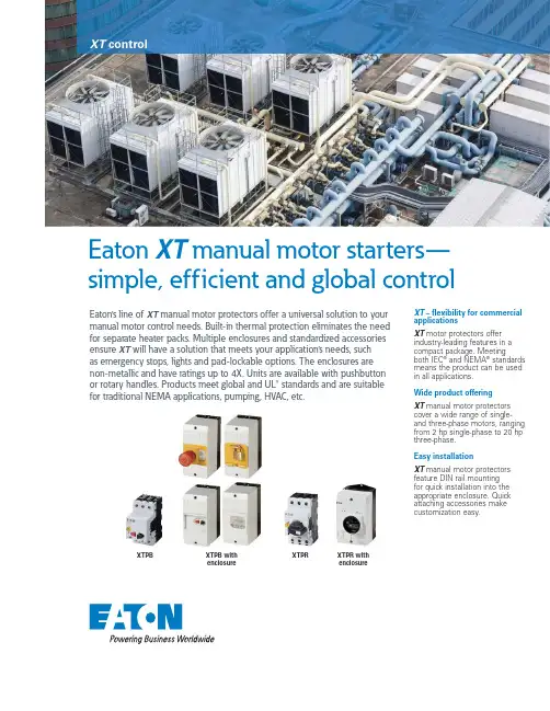
Eaton XT manual motor starters— simple, efficient and global controlEaton’s line of XT manual motor protectors offer a universal solution to your manual motor control needs. Built-in thermal protection eliminates the need for separate heater packs. Multiple enclosures and standardized accessories ensure XT will have a solution that meets your application’s needs, such as emergency stops, lights and pad-lockable options. The enclosures are non-metallic and have ratings up to 4X. Units are available with pushbutton or rotary handles. Products meet global and UL® standards and are suitable for traditional NEMA applications, pumping, HVAC, etc.XT – flexibility for commercial applicationsXT motor protectors offer industry-leading features in a compact package. Meetingboth IEC ® and NEMA ® standards means the product can be used in all applications. Wide product offeringXT manual motor protectors cover a wide range of single- and three-phase motors, ranging from 2 hp single-phase to 20 hp three-phase. Easy installationXT manual motor protectors feature DIN rail mounting for quick installation into the appropriate enclosure. Quick attaching accessories makecustomization easy.XTPBXTPB with enclosureXTPRXTPR withenclosureXT controlEaton is a registered trademark.All other trademarks are property of their respective owners.Eaton1000 Eaton Boulevard Cleveland, OH 44122United States © 2016 EatonAll Rights Reserved Printed in USAPublication No. PA122001EN / Z18550August 2016Manual motor protectorsCatalog Rated current FLAadjustment Maximum hp rating (three-phase)Maximum hp rating(single-phase)EnclosuresSurfaceFlushEnclosureotes:N Includes integrated neutral terminal. Enclosure only—order MMP and accessories separate.Indicating lights with neon bulbXTPAXILRBote:NIndicating light not UL Listed/Registered.Manual motorprotectors easily install in enclosuresFor additional information and accessories, visit /XT or reference the Eaton catalog—Volume 5, Tab 1.Follow us on social media to get the latest product and support information.。
美国Eaton公司VSA12、VSA16和VSA20型号的自动切换断路器功能说明说明书
ReclosersFunctional Specification GuideTypes VSA12, VSA16 and VSA20 ReclosersPS280014EN1 of 3 • Effective June 2017 • Supersedes all previousFunctional specification for Types VSA12, VSA16 and VSA20 reclosers1. Equipment Specifications1.1. Automatic circuit reclosers with vacuum interruption and air insulation2. Standards2.1. The recloser covered by this specification shall be designed, manufactured and tested in accordance withapplicable ANSI C37.60 and ANSI C37.61. 3. Quality3.1. The manufacturing facility shall be independently certified to meet ISO 9001 Standards.4. RatingsVSA12 VSA16 VSA20 Maximum Design Voltage (kV) 15.5 15.5 15.5 Nominal Operating Voltage (kV) 2.4-14.42.4-14.42.4-14.4 Basic Insulation Level-BIL (kV) 110 110 110 60 Hertz Withstand Voltage (kV) Dry, one minute 50 50 50Wet, ten seconds45 45 45 Max RIV at 1.0 MHZ/9.41 kV (microvolts) 100 100 100 Continuous Current rating (amps) 800 800 800 Symmetric Interrupting Current (amps)12,000 16,00020,000 Cable Charging Current (amps) 2 2 2 Magnetizing Current (amps) 28 28 28 General Purpose Capacitance Current 250 250 250Switching (amps)3 Second Current, Symmetric (amps) 12,000 16,000 20,000 Momentary Current, Asymmetric (amps) 19,20025,60032,0005. Mechanical Life5.1. 2500 Close-Open operations6. Duty cyclePERCENT OF NUMBER OF MAXIMUM INTERRUPTING UNIT CIRCUIT RATING OPERATIONS X/R RATIO 15-2088445-55 112 890-100 32 167. Features7.1. The recloser will be mechanically and electrically trip-free7.2. All three poles of the recloser will be operated simultaneously by a solenoid-spring operating mechanism.7.3. The recloser will be opened and closed by means of energy provided by a motor operating at 240 Vac, 60Hz and stored in springs for both tripping and closing operations.7.4. Bushings will be of “wet” process porcelain and will have a standard creepage distance of 12" inches. A17" creepage distance bushing will be available as an option.7.5. Bushing terminals will be of the universal clamp type and will accommodate conductors ranging in sizefrom 4/0 to 1000 MCM, inclusive,7.6. Current interruption will occur in vacuum interrupters, one interrupter per phase.7.7. It will be possible to replace one or all bushings without any re-alignment or adjustment of the vacuuminterrupters or operating mechanism.7.8. The recloser interrupting time will be 0.042 seconds7.9. Resistance-type heaters will be provided in the interrupter and operating mechanism cabinets, to preventmoisture condensation.7.10. The recloser will be shipped mounted in a substation mounting frame.7.11. The mounting frame extension will have a ground pad which will accommodate two No. 2/0 to 250 MCMconductors7.12. Sensing bushing current transformers, 1000:1 ratio, for use with the recloser control, will be mountedinternally in the recloser on bushings 1, 3, and 5.7.13. A 4 - digit counter will be provided in the operating mechanism.7.14. The recloser will use a motor operator to charge opening and closing springs; solenoids will be used forthe tripping and closing operations.7.15. A contact position indicator, externally visible, will be provided.7.16. Two external pull rings will be provided, one to close the recloser and one to trip the recloser.7.17. A spring operator condition indicator will be provided to indicate whether the closing springs are energized.The indicator consists of a mechanical flag for indication and will be visible from the front of the operatorcabinet.7.18. The recloser will be capable of manual trip and manual close on a maximum fault. Closing springs can becharged manually by means of a crank (150 turns), through a gear box.8. Spring Charging MotorSTANDARD ACCESSORYOperating voltage (Vac) 240 120Voltage Range (Vac) 160-257 90-127Maximum Current RMSA (amperes) 13 18Steady State Current (amperes) 8 9Motor Running Time (cycles) 40 409. Controls9.1. The recloser will be capable of operation with any of the following: Form 3, Form 3A, Form 4A or Form 4CType ME Recloser control.10. Approved ManufacturersEaton。
爱达顿HKW3400V系列电源保护设备说明说明书

Eaton HKW3400VEaton Series C complete molded case circuit breaker, K-frame, HKW, Complete breaker, Adjustable thermal, adjustable magnetic trip type, Three-pole, 400A, 600 Vac, 250 Vdc, 70 kAIC at 415 Vac, Line and load, 50°CGeneral specificationsEaton Series C complete molded case circuit breakerHKW3400V 7821169411244.1 in5.5 in5.5 in 11.84 lb Eaton Selling Policy 25-000, one (1) year from the date of installation of the Product or eighteen (18) months from the date of shipment of the Product, whichever occurs first.IEC Rated Product NameCatalog Number UPCProduct Length/Depth Product Height Product Width Product Weight WarrantyCertifications70 kAIC at 415 VacComplete breakerKHKW416-600 Vac or 220-250 Vdc right pigtail rear Complete breakerLine and load50°C600 Vac, 250 Vdc400 AAdjustable thermal, adjustable magnetic Three-pole Application of Tap Rules to Molded Case Breaker TerminalsUL listed 100%-rated molded case circuit breakersApplication of Multi-Wire Terminals for Molded Case Circuit BreakersCircuit breaker motor operators product aidPower metering and monitoring with Modbus RTU product aid StrandAble terminals product aidPlug-in adapters for molded case circuit breakers product aidMulti-wire lugs product aidMotor protection circuit breakers product aidCurrent limiting Series C molded case circuit breakers product aid Breaker service centersEaton's Volume 4—Circuit ProtectionMolded case circuit breakers catalogInstallation Instructions for DK, KDB, KD, HKD, KDC, KW, HKW, KWC, CKD, CHKD Circuit Breakers and Molded Case SwitchesInstruction Leaflet for the KES 310+ Electronic Trip UnitCircuit Breakers ExplainedCircuit breakers explainedSeries C F-Frame molded case circuit breakersEaton Specification Sheet - HKW3400VSeries C J-Frame molded case circuit breakers time current curves MOEM MCCB product selection guideSeries C G-Frame molded case circuit breakers time current curves Selling Policy 25-000 - Distribution and Control Products and ServicesInterrupt ratingTypeFrameCircuit breaker type Shunt tripCircuit breaker frame type TerminalsCalibrationVoltage rating Amperage RatingTrip TypeNumber of poles Application notesBrochuresCatalogsInstallation instructions MultimediaSpecifications and datasheets Warranty guidesEaton Corporation plc Eaton House30 Pembroke Road Dublin 4, Ireland © 2023 Eaton. All Rights Reserved. Eaton is a registered trademark.All other trademarks areproperty of their respectiveowners./socialmedia。
Bussmann 系列模块式保护器说明书
Recommended Bussmann series DIN-Rail end stops:
• Cat. no. BRKT-ND • Cat. no. BRKT-NDSCREW2
Table 3. Catalog numbers
#10-32 Phil-slot screw BCM603-1S BCM603-2S BCM603-3S
— — —
Screw with quick connect* BCM603-1SQ BCM603-2SQ BCM603-3SQ BMM603-1SQ BMM603-2SQ BMM603-3SQ
Poe class CC CC CC 10x38 (13/32”x1-1/2”) 10x38 (13/32”x1-1/2”) 10x38 (13/32”x1-1/2”) 3-Pole control circuit transformer block 2-pole CC with 1-pole 10x38 (13/32”x1-½”)
33
21
1.3
.8
40
60
1.6
2.4
77 10
3.0 .4
4
.2
39
20
20
1.6
59 2.3
.8
.8
16
.6
33
1.3
BMM603-3C with CVRI-CCM covers and TM26CB marker labels
The only controlled copy of this Data Sheet is the electronic read-only version located on the Bussmann Network Drive. All other copies of this document are by definition uncontrolled. This bulletin is intended to clearly present comprehensive product data and provide technical information that will help the end user with design applications. Bussmann reserves the right, without notice, to change design or construction of any products and to discontinue or limit distribution of any products. Bussmann also reserves the right to change or update, without notice, any technical information contained in this bulletin. Once a product has been selected, it should be tested by the user in all possible applications.
Eaton PDG33MH400E4MN 电源防御筒型电路保护器说明书
Eaton PDG33MH400E4MNPower Defense Globally Rated, Frame 3, Three Pole, 400A-High, 65kA/480V, PXR20 ARMS LSI w/ Modbus RTU and Relays, No TerminalsEaton Power Defense molded case circuit breakerPDG33MH400E4MN 786679472552109.1 mm 257.1 mm 138.9 mm 5.92 kg Eaton Selling Policy 25-000, one (1) year from the date of installation of theProduct or eighteen (18) months from thedate of shipment of the Product,whichever occurs first.RoHS Compliant UL 489IEC 60947-2CCC MarkedCSAProduct NameCatalog Number UPCProduct Length/Depth Product Height Product Width Product Weight WarrantyCompliancesCertifications400A High Override Complete breaker 3Three-polePD3 Global Class A PXR 20 LSI w/ARMSModbus RTU600 Vac600 VNo Terminals65 kAIC at 480 Vac 100 kAIC @240V (UL) 22 kAIC Icu @250 Vdc 400 A high overrideEaton Power Defense MCCB PDG33MH400E4MN 3D drawing Consulting application guide - molded case circuit breakers Power Xpert Protection Manager x64StrandAble terminals product aid Power Defense brochureAmperage Rating Circuit breaker frame type Frame Number of poles Circuit breaker type Class Trip TypeCommunication Voltage rating Voltage rating - max Terminals Interrupt rating Interrupt rating range Trip rating3D CAD drawing packageApplication notesBrochuresPower Defense molded case circuit breaker selection posterPower Defense technical selling bookletCatalogsMolded case circuit breakers catalogPower Xpert Release trip units for Power Defense molded case circuit breakersCertification reportsPDG3 CSA certification 100-400aPDG3B 450A-600A CB reportEU Declaration of Conformity - Power Defense molded case circuit breakersPDG3 45-400A CB reportPDG3 UL authorization 250-600a TMTUPDG3 UL authorization 250-600a PXRPDG3 CSA certification 250-600aPDG3 UL authorization 100-400aInstallation instructionsPower Defense Frame 1-2-3-4 IP door barrier assembly instructions - IL012278ENPower Defense Frame 3 interphase barrier - IL012229EN H03 Power Defense Frame 3 plug-in adapter installation instructions -IL012311ENPower Defense Frame 3 screw terminal end cap kit 600A, 3 pole -IL012264ENPower Defense Frame 4 locking devices and handle block instructions - IL012151ENPower Defense Frame 3 reverse feed connector kit Cat NumPDG3X3(2)(4)TA630RF instructions - IL012253ENPower Defense Frame 3 box terminal installation instructions -IL012299ENPower Defense Frame 3 multi-tap terminal kit Cat NumPDG3X3(2)(4)TA6006WSW instructions - IL012250ENPower Defense Frame 3 handle mech direct rotary handle instructions - IL012111ENPower Defense Frame 3 locking devices and handle block instructions - IL012150ENPower Defense Frame 3 terminal kit Cat Num PDG3X3(2)(4)TA400RF instructions - IL012251ENPower Defense Frame 3 shunt trip UVR instructions - IL012140EN Power Defense Frame 3 screw terminal_end cap kit, 400A, 3 pole – IL012262ENPower Defense Frame 3 trip unit replacement instructions - IL012157EN Power Defense Frame 3 Aux, Alarm, ST and UVR Animated Instructions.rh Power Defense Frame 4 shunt trip UVR instructions - IL012129EN Power Defense Frame 3 Direct Rotary Handle Assy With Interlock Version Instructions (IL012139EN).pdfPower Defense Frame 3 finger protection assembly installation instructions - IL012279ENPower Defense Frame 3 terminal cover assembly instructions -IL012281ENPower Defense Frame 3 rear connection installation instructions -IL012300ENPower Defense Frame 4 reverse feed connector kit instructions for PDG4X3(2)(4)TA800RF instructions - IL012254ENPower Defense Frame 3 interphase barriers 3-pole - IL012229EN H01 Power Defense Frame 3 multi-tap terminal kit Cat NumPDG3X3(2)(4)TA6006W Instructions - IL012248ENPower Defense Frame 3 reverse feed connector kit Cat NumPDG3X3(2)(4)TA400HRF instructions - IL012252ENPower Defense Frame 3 adapter kit installation instructions LZM3 to PD3 - IL012227ENPower Defense Frame 3 extendable shaft rotary handle mech -IL012112ENPower Defense Frame 3 multi wire connector kit -PDG3X3(2)(4)TA4006W and PDG3X3(2)(4)TA4003W instructions-IL012247EN H01Power Defense Frame 3 Breaker Instructions (IL012107EN).pdfPower Defense Frame 2/3/4/5/6 voltage neutral sensor module wiring instructions – IL012316ENPower Defense Frame 3 terminal spreader assembly instructions -IL012301ENInstallation videosPower Defense Frame 3 Handle Mech Variable Depth Rotary Handle Animated Instructions.rhPower Defense Frame 3 Shunt Trip_UVR Animated Instructions.pdf.rh Power Defense Frame 3 Handle Mech Direct Rotary Handle Animated Instructions.rhPower Defense Frame 3 Locking Devices and Handle Block Animated Instructions.pdf.rhPower Defense Frame 3 trip unit replacement animated instructions.rh MultimediaPower Defense Frame 3 Aux, Alarm, Shunt Trip, and UVR How-To Video Power Defense Frame 3 Direct Rotary Handle Mechanism InstallationEaton Corporation plc Eaton House30 Pembroke Road Dublin 4, Ireland © 2023 Eaton. All Rights Reserved. Eaton is a registered trademark.All other trademarks areproperty of their respectiveowners./socialmediaHow-To VideoPower Defense Frame 3 Trip Unit Installation How-To Video Power Defense molded case circuit breakersPower Defense Frame 2 Variable Depth Rotary Handle Mechanism Installation How-To Video Power Defense BreakersPower Defense Frame 6 Trip Unit How-To VideoPower Defense Frame 3 Variable Depth Rotary Handle Mechanism Installation How-To VideoPower Defense Frame 5 Trip Unit How-To Video Eaton Power Defense for superior arc flash safety Eaton Specification Sheet - PDG33MH400E4MN Power Defense time current curve Frame 3 - PD3Power Defense time current curves MCP Motor Circuit Protection – PD1, PD2, PD3Single and double break MCCB performance revisited Intelligent circuit protection yields space savings Making a better machineMolded case and low-voltage power circuit breaker healthImplementation of arc flash mitigating solutions at industrial manufacturing facilitiesIntelligent power starts with accurate, actionable data Safer by design: arc energy reduction techniques Molded case and low-voltage breaker healthSpecifications and datasheetsTime/current curvesWhite papers。
市场型微机综合保护技术说明书 (防跳)
微机保护测控装置技术使用说明书版本:V3.01*本说明书可能会被修改,请注意最新版本资料*技术部监制目录一.装置简介 (3)1.装置概述 (3)1.1装置简介 (3)1.2装置特点 (3)1.3引用标准 (3)1.4装置结构 (4)2主要技术指标 (5)2.1 技术参数 (5)2.2 环境参数 (6)2.2.1 电气环境 (6)2.2.2 自然环境 (7)2.2.3 机械环境 (7)二.微机保护测控装置 (8)1. 功能配置 (8)2.功能说明 (8)2.1 三段式相间过流保护 (8)2.2 过负荷保护 (10)2.3 三相一次重合闸 (10)2.4 相间合闸加速保护 (10)2.5 相间充电保护 (10)2.6 相间负序过流保护 (11)2.7 零序过流告警和跳闸保护 (11)2.8 过电压保护 (11)2.9 低电压保护 (11)2.10 零序过电压保护 (12)2.11 低周减载保护 (12)2.12 非电量保护 (12)2.13 系统异常工况报警及闭锁功能 (13)3.装置整定 (14)3.1 装置软压板整定 (14)3.2 装置定值整定 (14)3.3 装置参数整定 (16)4.附录 (17)4.1 装置背板图 (18)4.2 装置接线示意图 (18)三.使用说明 (19)1.1 装置介绍 (19)1.2液晶 (20)1.3 界面菜单 (20)1.4 模拟通道 (21)1.5 事件报告 (22)1.6 系统设置 (23)1.7 装置测试 (25)1.7.1 开出传动 (26)1.7.2 开入显示 (26)1.7.3 版本显示 (26)1.8 装置调试 (26)1.8.1 装置通电前检查 (26)1.8.2 绝缘检查 (27)1.8.3 上电检查 (27)1.8.4 采样精度检查 (27)1.8.5 接点输出校验 (27)1.8.6 定值校验 (27)1.8.7 跳合闸电流保持试验 (27)1.8.8 相序检查 (27)1.8.9 校准时钟 (27)2.安装 (28)一.装置简介1.装置概述1.1装置简介微机保护测控装置适用于110kV以下各电压等级的间隔单元的保护测控,具备完善的保护、测量、控制、进线备投自复及通信监视功能,为变电站、发电厂、高低压配电及厂用电系统的保护与控制提供了完整的解决方案,可有力地保障高低压电网及厂用电系统的安全稳定运行。
通用保护器10照明操作手册
危险!在操作手册中标有这个图标的地方是要您注意即将接近危险,可能的后果是:非常严重的伤害甚至死亡。
小心!标有这个图标的地方是要您注意危险状况。
可能的后果是:轻度或中度重伤和设备损坏。
重要!在操作手册中标有这个图标的地方提供了使您便于操作的提示和资料,不是有关有害或危险状况的警告。
■用黑色方块列出各项。
警告!当照明综保发生故障时,一定要先切断上一级电源才可开盖维修。
第一节安全指南综述这是本操作手册中所有各章节安全指南的一个摘要。
第三章储存和运输注意!安装前检查,整机装配良好,坚固螺栓无松动现象,手柄及按钮操作灵活。
通电试验,照明综保应无振动现象和明显噪声。
PDF created with pdfFactory trial version 警告!任何工作都要遵守本手册的安全指南,也要遵守矿方管理部门制订的特殊安全指南和操作手册,否则将导致最严重的事故,甚至造成死亡。
第一节安装照明综保安装前检查照明综保应装配良好,紧固螺栓无松动现象,手柄、按钮活动灵活,无卡滞现象。
接上电源,按下停止按钮,旋转隔离开关手柄到接通位置,显示屏亮,初始化完成后,按下起动按钮,检查动作是否正常可靠,照明综保应无振动现象和明显噪声。
第二节照明综保的使用条件及要求n适用于含有爆炸性气体环境(甲烷、煤尘)的煤矿井中;n在交流50Hz,电压为1140V或660V的线路中;n海拔不超过2000米,周围环境压力为(0.8~1.1)×105Pa;n周围环境温度为-5℃~+40℃;n周围空气相对湿度不大于95%(+25℃);n须防止水或其它液体浸入照明综保内部;n无剧烈振动、颠簸以及与水平面安装倾斜度不超过15°。
第三节测试运转注意!确保重新安装完运输时拆卸下来的所有固定元件。
PDF created with pdfFactory trial version 危险!您必须十分了解照明综保的操作方法,才能操作照明综保。
您必须经过对现有操作人员进行的作业培训,并通过实践加深对照明综保控制系统的了解。