mBPM 连接器使用手册
BPM平台说明书

技术文件技术文件名称:BPM平台应用说明书技术文件编号:WT-BPM-003版本:V1.0共 48页(包括封面)拟制方茂审核会签标准化批准华通科技有限公司目录1编写目的 (3)2术语、定义和缩略语 (3)2.1术语、定义 (3)2.2缩略语 (3)3模块描述 (3)3.1包划分及包关系 (3)4 B P M平台应用 (4)4.1第一部分项目开发环境搭建 (4)4.1.1项目下载 (4)4.1.2数据库配置、项目脚本生成 (5)4.1.3配置JBPM运行环境: (6)4.1.4利用BPM平台搭建项目开发环境: (8)4.2第二部分工作流流程配置 (10)4.2.1发布Jbpm流程图: (10)4.2.2生成菜单 (16)4.2.3执行流程 (17)4.2.4约定 (19)4.3第三部分主要数据库表的说明 (19)4.3.1BPM部分 (19)4.3.2IDP部分 (23)4.4第四部分数据库基础操作(mssql2005) (29)4.4.1还原(mssql2005) (29)4.4.2备份(mssql2005) (31)4.4.3Powerbuilder数据脚本生成 (33)5BPM主要接口,类,方法说明 (35)5.1com.wootion.bpm.jpbm 调用JPBM流程相关 (35)5.1.1com.wootion.bpm.jbpm.assignment.CurrencyAssignment.java (35)5.1.2com.wootion.bpm.jbpm.decision.CurrencyDecision.java (36)5.1.3com.wootion.bpm.jbpm.jbpmsession.JbpmSessionHandle.java (36)5.1.4com.wootion.bpm.jbpm.ProcessDefinitionUtil.java (36)5.2com.wootion.bpm.wfshow 流程展示模块 (36)5.2.1com.wootion.bpm.wfshow.action.ControlAction.java (36)5.2.2com.wootion.bpm.wfshow.action.ControlSaveAction.java (36)5.2.3com/wootion/bpm/wfshow/action/InspectAction.java (36)5.2.4com/wootion/bpm/wfshow/action/MyTaskListAction.java (37)5.2.5com/wootion/bpm/wfshow/action/WfListAction.java (37)5.2.6com/wootion/bpm/wfshow/action/WfShowAction.java (37)5.3com.wootion.bpm.bs 业务流程数据模块 (38)5.3.1com/wootion/bpm/bs/action/WfDealAction.java (38)5.3.2com/wootion/bpm/bs/bean/ApplicationRightContent.java (38)5.3.3com/wootion/bpm/bs/bean/DealContent.java (38)5.3.4com/wootion/bpm/bs/bean/DelContent.java (39)5.3.5com/wootion/bpm/bs/bean/PluginMgmtSession.java (39)5.3.6com/wootion/bpm/bs/bean/WfDealBean.java (39)5.3.7com/wootion/bpm/bs/operator/OperatorContent.java (39)5.3.8com/wootion/bpm/bs/GraphParamBean.java (40)5.3.9com/wootion/bpm/bs/GraphPDBean.java (40)5.3.10com/wootion/bpm/bs/GraphPDMessageBox.java (41)5.3.11com/wootion/bpm/bs/ModuleInstance.java (41)5.3.12com/wootion/bpm/bs/WfInstance.java (41)5.4com.wootion.mytask 我的任务管理类模块 (41)5.4.1com/wootion/mytask/inspect/InspectBean.java (41)5.4.2com/wootion/mytask/module/TaskActor.java (41)5.4.3com/wootion/mytask/name/NameUtil.java (42)5.4.4com/wootion/mytask/xml/TaskReader.java (42)5.4.5com/wootion/mytask/MyTaskCollector.java (42)5.5com.wootion.bpm.page 页面定义器模块 (42)5.5.1com/wootion/bpm/page/config/ShowConfigurePageBean.java (42)5.5.2com/wootion/bpm/page/data/plugin/DataPlugin.java (43)5.5.3com/wootion/bpm/page/data/service/ITBpmShowService.java (43)5.5.4com/wootion/bpm/page/data/DataDic.java (43)5.5.5com/wootion/bpm/page/data/ModuleData.java (43)5.5.6com/wootion/bpm/page/engine/BmpNodeTemplete.java (43)5.5.7com/wootion/bpm/page/engine/BpmFormTemplete.java (44)5.5.8com/wootion/bpm/page/list/DefaultListPageBean.java (44)5.5.9com/wootion/bpm/page/list/DefaultSearchPageBean.java (45)5.5.10com/wootion/bpm/page/list/SearchData.java (45)5.5.11com/wootion/bpm/page/transfers/HandleDataFromat.java (46)5.5.12com.wootion.bpm.page.module (46)5.5.13com.wootion.bpm.page.module.TextModule (46)5.5.14com.wootion.bpm.page.Node (46)5.6JBPM工具方法类(JBPMUtil.java) (47)5.6.1finishTaskInsOfNode():结束流程节点任务,扭转JBPM流程实例 (47)5.6.2assignAtStart():在流程发起节点分配任务实例 (47)5.6.3creatProcessIns():新增JBPM流程实例 (47)5.6.4getAvailableNodeOfpd():获得流程当前节点之后可经过的transition475.6.5setVariableOfProcessIns():将变量值存储到指定的JBPM实例中 (47)5.6.6getNameOfProcessState():获得指定流程实例的当前节点名 (47)5.6.7getVariableOfProcessIns():获得指定JBPM实例对象的键对应的值 (47)5.6.8getMyTaskList():获得指定用户名的角色的所有任务 (47)5.6.9getAllProcessList():获得所有流程的最新版本 (47)1编写目的本文件规定了华通科技工作流系统中各成分的设计考虑。
MiCOM P12y使用说明书

在可翻开的下盖板的下面,有一个电池舱,可使用½AA 型电池。该电池可作
为后备电源,保存保护装置存储器中的事件记录,故障记录和故障录波(仅对
P126 和 P127)。盖板下还有一个 9 针的母 D 型前部通讯端口。它的作用是通过
RS232 串行数据连接(SK1 口),在本地实现 PC 机和保护装置的通讯(最长距离
且跳闸原因也被复位后,指示灯熄
灭。
警告指示灯(L3:桔黄色 LED 指示灯,标注为 Warning):
灯亮表示 MiCOM P12y 保护装置有内部警告。当检测到一个“非严重”的内部 警告时,该指示灯将持续闪烁。只有当导致内部警告的原因不存在了(修理模块,故 障消失等),指示灯才会熄灭。
辅助电源(L4:绿色 LED 指示灯,标注为 Aux. Supply):
灯亮表示 MiCOM P12y 保护装置工作正常,装置电源的辅助电源存在。
可自由编程的指示灯(L5 to L8:标签自由标注):
这些 LED 指示灯可以由用户以提供的门槛(瞬动和延时信号)信息为基础自由 编程。用户选择他想用指示灯看到的信号,通过菜单将它们分配到每一个 LED 指示 灯上(用逻辑 OR)。当相关信号启动时,对应的指示灯亮。当相应的报警被确认了 之后,指示灯熄灭。
第 3 页/共 24 页 使用说明书
21 21 21 21 21 22 22 23 23 23 24 24 24
上海阿海珐电力自动化有限公司 MiCOMP12y 系列
第 4 页/共 24 页 使用说明书
1. 装置介绍
MiCOM P125、P126、P127 系列保护装置是法国 AREVA 公司继 K 系列、 MODN 系列以及 MX3 系列产品获得成功后新研制的换代产品。所设计的 MiCOM P125、 P126、P127 保护装置具有保护、控制和监视等多重功能,适用于工业, 配电网络和变电站中,可作为变压器和发电机变压器保护方案的一部分以及为高压 和超高压输电系统提供后备保护等。
米高M3P说明书

MICOLIFT M3P 微机使用说明书目录第一章简要介绍1.1前言___________________________________________________31.2功能简介_______________________________________________31.3附电梯专用控制系统功能_________________________________5第二章接口2.1MICOLIFT M3P配双速的端子连接________________________72.2MICOLIFT M3P配变频的端子连接________________________12图1:MICOLIFT M3P配双速端子接线图_________________________19图2:MICOLIFT M3P配变频端子接线图_________________________20图3:MICOLIFT M3P尺寸图___________________________________21第三章M3P调试器使用说明3.1显示屏、菜单___________________________________________223.2菜单描述_______________________________________________233.2.1 主菜单________________________________________________243.2.2 配置菜单(CONFIG) _____________________________________243.2.3 时间设置菜单(TIME) ___________________________________293.2.4 基站的设定(STATION) __________________________________303.2.5 呼梯菜单(CALL) _______________________________________323.2.6 输入输出菜单(IO菜单) _________________________________343.2.7 开门菜单(DOOR) ________________________________________353.2.8 故障记录菜单(ERROR HISTORY) ___________________________3613.2.9 密码菜单(PASSWORD) ____________________________________363.2.10脉冲监控菜单(PULSE MONITOR) ___________________________373.2.11输入选择菜单(INPUT SELECT)___________________________393.2.12时间菜单(TIME2)______________________________________403.3 自动测量井道数据方法_____________________________________403.4 电梯平层精度的调节_______________________________________413.5 减速距离的确定___________________________________________42第四章 故障描述_________________________________________________43 2第一章 简要介绍1.1 前言MICOLIFT M3P 全电脑控制微机自推出以来,以其无可比拟的可靠性、友好的人机界面,低廉的价格,迅速赢得了广大用户的信赖,成为电梯生产、改造及技术更新的首选产品,为当今电梯技术发展的主流方向。
Mini Beamer 传输器与接收器快速使用指南说明书
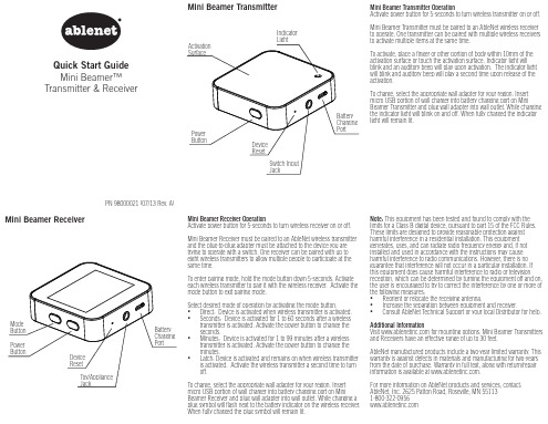
Note: This equipment has been tested and found to comply with the limits for a Class B digital device, pursuant to part 15 of the FCC Rules. These limits are designed to provide reasonable protection against harmful interference in a residential installation. This equipment generates, uses, and can radiate radio frequency energy and, if not installed and used in accordance with the instructions may cause harmful interference to radio communications. However, there is no guarantee that interference will not occur in a particular installation. If this equipment does cause harmful interference to radio or television reception, which can be determined by turning the equipment off and on, the user is encouraged to try to correct the interference by one or more of the following measures: • Reorient or relocate the receiving antenna. • Increase the separation between equipment and receiver. • Consult AbleNet Technical Support or your local Distributor for help.
MZM 100 B ST-1P2PW2RE-A 自动锁定闸电机监控连接器说明书

DATASHEETDataOrdering dataProduct type description MZM 100 B ST-1P2PW2RE-A Article number (order number)101211068EAN (European Article Number)4030661389103eCl@ss number, version 9.027-27-26-03eCl@ss number, version 11.027-27-26-03eCl@ss number, version 12.027-27-26-03ETIM number, version 7.0EC002593ETIM number, version 6.0EC002593Approvals - StandardsCertificates TÜVcULusEACGeneral dataStandards EN 60947-5-3EN ISO 13849-1EN ISO 14119IEC 61508Coding Universal codingLowCoding level according to ISO14119Working principle inductiveEnclosure material Glass-fibre, reinforced thermoplastic Gross weight645 gTime to readiness, maximum4,000 msReaction time, maximum150 msDuration of risk, maximum150 msGeneral data - FeaturesPower to lock YesActuator monitored YesLatching YesShort circuit detection YesCross-circuit detection YesSeries-wiring YesSafety functions YesIntegral system diagnostics, status YesNumber of safety contacts2Number of series-wiring of sensors31Safety classificationStandards EN ISO 13849-1IEC 61508Safety classification - Interlocking functionPerformance Level, up to eCategory4PFH value 3.54 x 10⁻⁹ /hSafety Integrity Level (SIL),3suitable for applications inMission time20 Year(s)Mechanical dataMechanical life, minimum1,000,000 OperationsNote (Mechanical life)Actuating speedOperations for door weights ≤ 5 kg Holding force, typically750 NHolding force, guaranteed500 NLatching force, minimum30 NLatching force, maximum100 NMechanical data - Connection techniqueType of connection Connector M23, 8+1-poleMechanical data - DimensionsLength of sensor40 mmWidth of sensor40 mmHeight of sensor179 mmAmbient conditionsDegree of protection IP65IP67Ambient temperature, minimum-25 °CAmbient temperature, maximum+55 °CStorage and transport-25 °Ctemperature, minimum+70 °CStorage and transporttemperature, maximumRelative humidity, minimum30 %Relative humidity, maximum95 %Note (Relative humidity)non-condensingnon-icingResistance to vibration to EN10 … 150 Hz, amplitude 0.35 mm60068-2-6Restistance to shock30 g / 11 msProtection class IIIAmbient conditions - Insulation valuesRated insulation voltage U32 VDCiRated impulse withstand voltage U0.8 kVimpOvervoltage category IIIDegree of pollution to VDE 01003Electrical dataOperating voltage, minimum20.4 VDCOperating voltage, maximum26.4 VDC600 mANo-load supply current, maximum IOperating current50 mARequired rated short-circuit100 Acurrent to EN 60947-5-1Note Cable length and cable section alter the voltage drop depending on the outputcurrentSwitching frequency, maximum 1 HzElectrical data - Magnet controlSwitching thresholds-3 V … 5 V (Low)15 V … 30 V (High) Classification ZVEI CB24I, Sink C0Classification ZVEI CB24I, Source C1C2C3Electrical data - Safety digital inputsSwitching thresholds−3 V … 5 V (Low)15 V … 30 V (High) Classification ZVEI CB24I, Sink C1Classification ZVEI CB24I, Source C1C2C3Electrical data - Safety digital outputs250 mARated operating current (safetyoutputs), maximum 1 VVoltage drop Ud0.5 mALeakage current IrVoltage, Utilisation category DC-1324 VDCCurrent, Utilisation category DC-130.25 A Classification ZVEI CB24I, Source C1Classification ZVEI CB24I, Sink C1Electrical data - Diagnostic outputs, maximum 2 VVoltage drop UdVoltage, Utilisation category DC-1324 VDCCurrent, Utilisation category DC-130.05 AStatus indicationNote (LED switching conditions display)Operating condition: LED green Error / functional defect: LED red Supply voltage UB: LED greenPin assignmentPIN 1A1 Supply voltage UBPIN 2X1 Safety input 1PIN 3A2 GNDPIN 4Y1 Safety output 1PIN 5OUT Diagnostic outputPIN 6X2 Safety input 2PIN 7Y2 Safety output 2PIN 8IN Solenoid controlPIN 9without functionScope of deliveryScope of delivery Actuators must be ordered separately.AccessoryRecommendation (actuator)MZM 100-B1.1NoteNote (General)As long as the actuating unit is applied to the solenoid interlock, the unlockedsafety guard can be relocked. In this case, the safety outputs are re-enabled, sothat the safety guard must not be opened.Ordering codeProduct type description:MZM 100(1)(2)(3)(4)(5)(1)without Solenoid interlock monitoredB Actuator monitored(2)ST2Connector plug M12, 8-poleST Connector plug M23, 8+1-pole(3)1P2P 1 p-type diagnostic output and 2 p-type safety outputs(only in connection with "Solenoid interlock monitored") 1P2PW serial diagnostic output and 2 p-type safety outputs(4)without electrically adjustable latching force 30 … 100 N(5)PicturesProduct picture (catalogue individual photo)ID: kmzm1f08| 1.4 MB | .jpg | 216.253 x 833.261 mm - 613 x 2362 px - 72 dpi| 235.7 kB | .png | 74.083 x 285.397 mm - 210 x 809 px - 72 dpiDimensional drawing basic componentID: 1mzm1g14| 20.7 kB | .swf || 5.2 kB | .png | 74.083 x 50.8 mm - 210 x 144 px - 72 dpi| 160.8 kB | .jpg | 352.778 x 242.358 mm - 1000 x 687 px - 72dpiDimensional drawing miscellaneousID: 1mzm1g15| 12.9 kB | .swf || 290.8 kB | .jpg | 352.425 x 362.656 mm - 999 x 1028 px - 72dpiWiring exampleID: kmzm1l03| 37.0 kB | .cdr || 86.9 kB | .jpg | 352.778 x 161.572 mm - 1000 x 458 px - 72 dpiContact arrangementID: km23-k9d| 18.5 kB | .cdr || 5.4 kB | .png | 74.083 x 77.611 mm - 210 x 220 px - 72 dpi| 149.1 kB | .jpg | 352.778 x 369.711 mm - 1000 x 1048 px - 72dpiSchmersal, Inc., 15 Skyline Drive, Hawthorne, NY 10532The details and data referred to have been carefully checked. Images may diverge from original. Further technical data can be found in the manual. Technical amendments and errors possible.Generated on: 6/28/2022, 2:51 AM。
BPM系统使用手册

浙江春风动力BPM系统使用手册目录登录 (2)导航条 (2)BPM系统---“个人常用” (2)进入“个人常用”导航页 (2)流程管理 (2)发起流程 (2)代办事项 (2)我的申请 (2)我处理的流程 (2)所有可查看的流程 (2)草稿箱 (2)个人信息 (2)修改密码 (2)个人信息 (2)考勤汇总 (2)打卡记录 (2)内部邮箱 (2)新建邮件 (2)代办邮件 (2)我的邮件 (2)已阅邮件 (2)BPM系统---“知识文档” (2)新增知识文档 ..................................................................................... 错误!未定义书签。
查看知识文档 (2)文档浏览 .............................................................................................. 错误!未定义书签。
登录1.浏览器环境A、IE浏览器:IE 9以上版本B、谷歌浏览器C、火狐浏览器D、360浏览器:极速模式E、搜狗浏览器:高速模式2.打开浏览器输入内网:http://192.168.1.241:88外网::88/3.分别输入账号和密码4.点击登录,如下图:导航条5.工作门户显示常用到的应用模块,如通知公告、代办流程、工作延误曝光台、代办邮件、待处理任务和工作周报等。
6.流程中心快速发起各种类别的流程:7.新闻门户8.功能图标BPM系统---“个人常用”进入“个人常用”导航页鼠标放在目录图标下小箭头处展开所有办事目录流程管理发起流程点击搜索图标,输入搜索关键字,再次点击搜索图标,即完成搜索。
1、生产设备(工装检具)采购申请为例A.提交确认表单填写无误后,点击提交按钮:B.存为草稿点击存为草稿按钮,在流程管理—草稿箱中可查看该条记录C.启用加签加签人:协作一起处理该流程的人员平行加签:加签人处理后,该流程进入到下一节点回到本关卡:加签人处理后,该流程流程回到原节点审批人处,需原节点审批人处理后进入下一节点停用加签代办事项显示所有需要登录人处理的流程信息功能介绍:当给予该登录人所在的审批结点以上按钮的权限时,按钮可点击,若显示为灰色不能点击时,该登录人对选中的代办流程没有操作权限。
mophie charge stream pad mini 用户手册说明书

WelcomeThank you for purchasing the mophie® charge stream™ pad mini. The charge stream pad mini will wirelessly charge Apple and Samsung Qi-compatible smartphones, mophie cases with wireless charging, and other devices with Qi wireless technology. The mophie charge stream pad mini charges on contact. Package contains•mophie charge stream pad mini• Micro-USB cable• Quick-start guideFeatures• Charges on contact. Simply place an Apple or Samsung Qi-compatible smartphone, a mophiecase with wireless charging, or other device withQi wireless technology on the charge streampad mini to immediately begin charging.• The rubberized top with built-in microsuction pad help your device stay in place to maintaina constant connection while it’s wirelesslycharging, and protect your device from scratches.• Low standby current draw lets you leave the wireless charging pad plugged in when it’s notin use.• Compact design for use in the office or at home.CompatibilityThe mophie charge stream pad mini will wirelessly charge Apple and Samsung Qi-compatible smartphones, mophie cases with wireless charging, and other devices with Qi wireless technology. Note: The charge stream pad mini will not fast charge devices capable of being fast charged. It will charge them at the standard Qi charging power of up to 5 watts.Charging your wireless device1. Remove the protective film from themicrosuction pad.2. Use the supplied micro-USB cable to connectthe charging pad to an adapter capable of atleast 1.8 amps.3. Place the wireless device on the charging padas shown in the illustration below. Make sure the center of the device is aligned over the center of the charging pad. Charging will begin on contact.Charging status indicatorThe charging pad has an LED that indicates its charging status:LED illuminated continuously:• The wireless device is properly charging.LED flashing continuously:• A metallic foreign object (keys, etc.) has been detected on the charging pad.Taking care of your charging pad• Keep your wireless charging pad dry and away from moisture and corrosive materials.• Do not clean your wireless charging pad with harsh chemicals, soaps or detergents. Just wipeit with a soft, water-dampened cloth.• Use a piece of tape to clean any dust and dirt from the microsuction pad on top of the charger. WarrantyAt mophie, we are dedicated to making the best quality products. To back this up, this product is warranted for 2 years. For full details regarding warranty terms and exclusions, please visit: /warranty. This warranty does not affect any statutory rights that you may be entitled to. K eep a copy of your purchase receipt as proof of purchase. Be sure to register your product at. Failure to register your product and/or provide proof of purchase may void the warranty. Exclusions & LimitationsExcept for the limited warranty expressly set forth or to the extent restricted or prohibited by applicable law, mophie expressly disclaims any and all other warranties express or implied, including any warranty of quality, merchantability, or fitness for a particular purpose, and you specifically agree that mophie shall not be liable for any special, incidental, indirect, punitive, or consequential damages of any type on any mophie product. In addition to and without limiting the generality of the foregoing disclaimers, the limited warranty does not, under any circumstances, cover the replacement or cost of any electronic device or personal property inside or outside of the mophie product.You may have additional warranty rights depending on your country, state or province. Further, some countries, states and provinces do not allow the exclusion or limitation of incidental or consequential damages or exclusions or limitations on the duration of implied warranties, so the above may not apply to you. If any provision of the warranty is found unlawful, void or unenforceable, that provision shall be deemed severable and shall not affect any remaining provision.Customer serviceTelephone: 1-888-8mophieInternational: +1 (269) 743-1340Web: /csWarningRead all instructions and warnings prior to using this product. Improper use of this product may result in product damage, excess heat, toxic fumes, fire, or explosion, for which damages you (“Purchaser”), and not mophie llc (“Manufacturer”) are responsible.N Do not store device in high-temperature environment, including heat caused by intense sunlight or other forms of heat. Donot place device in fire or other excessivelyhot environments.N Do not disassemble this device or attempt to re-purpose or modify it in any manner.N For questions or instructions for the various ways to charge using this device refer tothe Charging Your Wireless Device section ofthis manual.N Do not attempt to replace any part of this device. N If this device is accessible to or may be used by a minor, purchasing adult agrees to besolely responsible for providing supervision,instruction, and warnings. Purchaser agreesto defend, indemnify, and hold Manufacturerharmless for any claims or damages arisingfrom unintended use or misuse by a minor.N All products have gone through a thorough quality assurance inspection. If you find thatyour device is excessively hot, is emitting odor,is deformed, abraded, cut or is experiencingor demonstrating an abnormal phenomenon,immediately stop all product use and contact Manufacturer.N To comply with FCC RF exposure compliance requirements, the wireless charging pad mustbe used with a separation distance of at least 10cm from all persons.LegalThis product is meant for use only in conjunction with the appropriate device. Please consult your device packaging to determine whether this product is compatible with your particular device. Manufacturer is not responsible for any damages to any device incurred through the use of this product. Manufacturer shall not in any way be liable to you or to any third party for any damages you or any third party may suffer as a result of use, intended or unintended, or misuse of this product in conjunction with any device or accessory other than the appropriate device for which this product is designed. Manufacturer will not be responsible forany damages you or any third party may suffer as a result of misuse of this product as outlined above. Purchaser agrees to defend, indemnify, and hold Manufacturer harmless for any claims or damages arising from unintended use or misuse, including use with an unintended device.mophie, charge stream, Stay Powerful, mophie loves you, the five-circles design, and the mophie logo are trademarks of mophie inc. Apple is a trademark of Apple Inc. Samsung is a trademark of Samsung Electronics Co., Ltd. The ‘Qi’ symbol is a trademark of the Wireless Power Consortium. All rights reserved. Patents: /patents.This device complies with part 15 of the FCC Rules and RSS-Gen of IC Rules. Operation is subject to the following two conditions: (1) This device may not cause harmful interference, and (2) this device must accept any interference received, including interference that may cause undesired operation. NOTE: This equipment has been tested and found to comply with the limits for a Class B digital device, pursuant to part 15 of the FCC Rules. These limits are designed to provide reasonable protection against harmful interference in a residential installation. This equipment generates, uses, and can radiate radio frequency energy and, if not installed and used inaccordance with the instructions, may cause harmful interference to radio communications. However, there is no guarantee that interference will not occur in a particular installation.If this equipment does cause harmful interference to radio or television reception, which can be determined by turning the equipment off and on, the user is encouraged to try to correct the interference by one or more of the following measures:• Reorient or relocate the receiving antenna.• Increase the separation between the equipment and receiver.• Connect the equipment into an outlet on a circuit different from that to which the receiveris connected.• Consult the dealer or an experienced technician for help.CAUTION: To comply with the limits of the Class B digital device, pursuant to Part 15 of the FCC Rules, this device must be used with certified peripherals and shielded cables. All peripherals must be shielded and grounded. Operation with non-certified peripherals or non-shielded cables may result in interference to radio or reception.MODIFICATION: Any changes or modifications of this device could void the warranty.Statement of ComplianceHereby, ZAGG International declares that the radio equipment wireless charging pad is in compliance with Directive 2014/53/EU. The full text of the EU declaration of conformity is available at the following internet address: /cert_red WEEE DeclarationAll of our products are marked with the WEEE symbol; this indicates that this product must NOT be disposed of with other waste. Instead it is the user’s responsibility to dispose of their waste electrical and electronic equipment by handing it over to an approved re-processor, or by returning it to mophie inc. for reprocessing. For more information about where you can send your waste equipment for recycling, please contact mophie inc. or one of your local distributors.CRE-0650-B。
Bulgin M5 Buccaneer连接器产品说明书

BUCCANEERM5 SeriesSecure & reliable screw locking mechanism Robust PVC & PUR overmolded cables Cable length from 1m - 15mHigh degree of environmental protection - IP67 ratedThe most compact connector type in the M-Series range, Bulgin’s waterproof M5 sensor connectors come in straight and angled forms with PVC or PUR overmolded cable option s and a variety of panel mount receptacles.With an industry standard screw coupling mechanism and IP67 rating, this circular connector product line is particularly suited to automotive, process control, commercial electronics & instrumentation applications that require reliable and robust miniature sensors.Straight & right angled cable connectors Rear & front panel mount receptacles Available with 3 or 4 polesKey features:Part NumberPolesCodeTermination Lead Length PXMBNI05RPF03AFL00103A Flying Lead 100 mm Lead LengthPXMBNI05RPF03AFL00203A Flying Lead 200 mm Lead Length PXMBNI05RPF03AFL00303A Flying Lead 300 mm Lead Length PXMBNI05RPF04AFL00104A Flying Lead 100 mm Lead Length PXMBNI05RPF04AFL00204A Flying Lead 200 mm Lead Length PXMBNI05RPF04AFL00304A Flying Lead 300 mm Lead LengthPXMBNI05RPF03APC 03A PCB Terminal -PXMBNI05RPF04APC04APCB Terminal-Part NumberPoles Code Termination Lead Length PXMBNI05RPM03AFL00103A Flying Lead 100 mm Lead Length PXMBNI05RPM03AFL00203A Flying Lead 200 mm Lead Length PXMBNI05RPM03AFL00303A Flying Lead 300 mm Lead Length PXMBNI05RPM04AFL00104A Flying Lead 100 mm Lead Length PXMBNI05RPM04AFL00204A Flying Lead 200 mm Lead Length PXMBNI05RPM04AFL00304A Flying Lead 300 mm Lead LengthPXMBNI05RPM03APC 03A PCB Terminal -PXMBNI05RPM04APC04APCB Terminal-○ Rear panel mounting M5 nut ○ Mates with Flex Body connectors M5 Rear Panel Mounting FemalePXMBNI05RPFM5 Rear Panel Mounting MalePXMBNI05RPM○ Available in 3 and 4 poles ○ PCB or flying lead termination ○ Rear panel mounting M7 nut ○ Available in 3 and 4 poles ○ PCB or flying lead termination ○ Mates with Flex Inline Body connectorsPart NumberPoles Code Termination Lead Length PXMBNI05FPM03AFL00103A Flying Lead 100 mm Lead Length PXMBNI05FPM03AFL00203A Flying Lead 200 mm Lead Length PXMBNI05FPM03AFL00303A Flying Lead 300 mm Lead Length PXMBNI05FPM04AFL00104A Flying Lead 100 mm Lead Length PXMBNI05FPM04AFL00204A Flying Lead 200 mm Lead Length PXMBNI05FPM04AFL00304A Flying Lead 300 mm Lead LengthPXMBNI05FPM03APC 03A PCB Terminal -PXMBNI05FPM04APC04APCB Terminal-○ PCB or flying lead termination ○ Rear panel mounting M5M5 Front Panel Mounting Male○ Available in 3 and 4 poles ○ Mates with Flex Body connectors PXMBNI05FPMM5 Right Angled FemalePXPTPU05RAF Part NumberPoles Code Termination Lead Length Cable MaterialPXPPVC05RAF03ACL010PVC 03A Overmold Cable 1 M Lead Length PVC PXPTPU05RAF03ACL010PUR 03A Overmold Cable 1 M Lead Length PUR PXPPVC05RAF03ACL020PVC 03A Overmold Cable 2 M Lead Length PVC PXPTPU05RAF03ACL020PUR 03A Overmold Cable 2 M Lead Length PUR PXPPVC05RAF03ACL030PVC 03A Overmold Cable 3 M Lead Length PVC PXPTPU05RAF03ACL030PUR 03A Overmold Cable 3 M Lead Length PUR PXPPVC05RAF03ACL050PVC 03A Overmold Cable 5 M Lead Length PVC PXPTPU05RAF03ACL050PUR 03A Overmold Cable 5 M Lead Length PUR PXPPVC05RAF03ACL100PVC 03A Overmold Cable 10 M Lead Length PVC PXPTPU05RAF03ACL100PUR 03A Overmold Cable 10 M Lead Length PUR PXPPVC05RAF03ACL150PVC 03A Overmold Cable 15 M Lead Length PVC PXPTPU05RAF03ACL150PUR 03A Overmold Cable 15 M Lead Length PUR PXPPVC05RAF04ACL010PVC 04A Overmold Cable 1 M Lead Length PVC PXPTPU05RAF04ACL010PUR 04A Overmold Cable 1 M Lead Length PUR PXPPVC05RAF04ACL020PVC 04A Overmold Cable 2 M Lead Length PVC PXPTPU05RAF04ACL020PUR 04A Overmold Cable 2 M Lead Length PUR PXPPVC05RAF04ACL030PVC 04A Overmold Cable 3 M Lead Length PVC PXPTPU05RAF04ACL030PUR 04A Overmold Cable 3 M Lead Length PUR PXPPVC05RAF04ACL050PVC 04A Overmold Cable 5 M Lead Length PVC PXPTPU05RAF04ACL050PUR 04A Overmold Cable 5 M Lead Length PUR PXPPVC05RAF04ACL100PVC 04A Overmold Cable 10 M Lead Length PVC PXPTPU05RAF04ACL100PUR 04A Overmold Cable 10 M Lead Length PUR PXPPVC05RAF04ACL150PVC 04A Overmold Cable 15 M Lead Length PVC PXPTPU05RAF04ACL150PUR 04AOvermold Cable15 M Lead LengthPUR○ 1,2,3,5,10 & 15M cable options ○ Overmold Flex BodyPXPPVC05RAF○ Available in 3 and 4 poles ○ Mates with Flex Inline Body & panel mount connectorsM5 Right Angled MalePXPTPU05RAM Part NumberPoles Code Termination Lead Length Cable MaterialPXPPVC05RAM03ACL010PVC 03A Overmold Cable 1 M Lead Length PVC PXPTPU05RAM03ACL010PUR 03A Overmold Cable 1 M Lead Length PUR PXPPVC05RAM03ACL020PVC 03A Overmold Cable 2 M Lead Length PVC PXPTPU05RAM03ACL020PUR 03A Overmold Cable 2 M Lead Length PUR PXPPVC05RAM03ACL030PVC 03A Overmold Cable 3 M Lead Length PVC PXPTPU05RAM03ACL030PUR 03A Overmold Cable 3 M Lead Length PUR PXPPVC05RAM03ACL050PVC 03A Overmold Cable 5 M Lead Length PVC PXPTPU05RAM03ACL050PUR 03A Overmold Cable 5 M Lead Length PUR PXPPVC05RAM03ACL100PVC 03A Overmold Cable 10 M Lead Length PVC PXPTPU05RAM03ACL100PUR 03A Overmold Cable 10 M Lead Length PUR PXPPVC05RAM03ACL150PVC 03A Overmold Cable 15 M Lead Length PVC PXPTPU05RAM03ACL150PUR 03A Overmold Cable 15 M Lead Length PUR PXPPVC05RAM04ACL010PVC 04A Overmold Cable 1 M Lead Length PVC PXPTPU05RAM04ACL010PUR 04A Overmold Cable 1 M Lead Length PUR PXPPVC05RAM04ACL020PVC 04A Overmold Cable 2 M Lead Length PVC PXPTPU05RAM04ACL020PUR 04A Overmold Cable 2 M Lead Length PUR PXPPVC05RAM04ACL030PVC 04A Overmold Cable 3 M Lead Length PVC PXPTPU05RAM04ACL030PUR 04A Overmold Cable 3 M Lead Length PUR PXPPVC05RAM04ACL050PVC 04A Overmold Cable 5 M Lead Length PVC PXPTPU05RAM04ACL050PUR 04A Overmold Cable 5 M Lead Length PUR PXPPVC05RAM04ACL100PVC 04A Overmold Cable 10 M Lead Length PVC PXPTPU05RAM04ACL100PUR 04A Overmold Cable 10 M Lead Length PUR PXPPVC05RAM04ACL150PVC 04A Overmold Cable 15 M Lead Length PVC PXPTPU05RAM04ACL150PUR 04AOvermold Cable15 M Lead LengthPURPXPPVC05RAM○ Available in 3 and 4 poles ○ 1,2,3,5,10 & 15M cable options ○ Overmold Flex Inline Body○ Mates with Flex Body & panel mount connectorsM5 Flex Body FemalePXPTPU05FBF Part NumberPoles Code Termination Lead Length Cable MaterialPXPPVC05FBF03ACL010PVC 03A Overmold Cable 1 M Lead Length PVC PXPTPU05FBF03ACL010PUR 03A Overmold Cable 1 M Lead Length PUR PXPPVC05FBF03ACL020PVC 03A Overmold Cable 2 M Lead Length PVC PXPTPU05FBF03ACL020PUR 03A Overmold Cable 2 M Lead Length PUR PXPPVC05FBF03ACL030PVC 03A Overmold Cable 3 M Lead Length PVC PXPTPU05FBF03ACL030PUR 03A Overmold Cable 3 M Lead Length PUR PXPPVC05FBF03ACL050PVC 03A Overmold Cable 5 M Lead Length PVC PXPTPU05FBF03ACL050PUR 03A Overmold Cable 5 M Lead Length PUR PXPPVC05FBF03ACL100PVC 03A Overmold Cable 10 M Lead Length PVC PXPTPU05FBF03ACL100PUR 03A Overmold Cable 10 M Lead Length PUR PXPPVC05FBF03ACL150PVC 03A Overmold Cable 15 M Lead Length PVC PXPTPU05FBF03ACL150PUR 03A Overmold Cable 15 M Lead Length PUR PXPPVC05FBF04ACL010PVC 04A Overmold Cable 1 M Lead Length PVC PXPTPU05FBF04ACL010PUR 04A Overmold Cable 1 M Lead Length PUR PXPPVC05FBF04ACL020PVC 04A Overmold Cable 2 M Lead Length PVC PXPTPU05FBF04ACL020PUR 04A Overmold Cable 2 M Lead Length PUR PXPPVC05FBF04ACL030PVC 04A Overmold Cable 3 M Lead Length PVC PXPTPU05FBF04ACL030PUR 04A Overmold Cable 3 M Lead Length PUR PXPPVC05FBF04ACL050PVC 04A Overmold Cable 5 M Lead Length PVC PXPTPU05FBF04ACL050PUR 04A Overmold Cable 5 M Lead Length PUR PXPPVC05FBF04ACL100PVC 04A Overmold Cable 10 M Lead Length PVC PXPTPU05FBF04ACL100PUR 04A Overmold Cable 10 M Lead Length PUR PXPPVC05FBF04ACL150PVC 04A Overmold Cable 15 M Lead Length PVC PXPTPU05FBF04ACL150PUR 04AOvermold Cable15 M Lead LengthPURPXPPVC05FBF○ Available in 3 and 4 poles ○ Overmold Flex Body○ 1,2,3,5,10 & 15M cable options ○ Mates with Flex Inline Body & panel mount connectorsM5 Flex Inline Body MalePXPTPU05FIM Part NumberPoles Code Termination Lead Length Cable MaterialPXPPVC05FIM03ACL010PVC 03A Overmold Cable 1 M Lead Length PVC PXPTPU05FIM03ACL010PUR 03A Overmold Cable 1 M Lead Length PUR PXPPVC05FIM03ACL020PVC 03A Overmold Cable 2 M Lead Length PVC PXPTPU05FIM03ACL020PUR 03A Overmold Cable 2 M Lead Length PUR PXPPVC05FIM03ACL030PVC 03A Overmold Cable 3 M Lead Length PVC PXPTPU05FIM03ACL030PUR 03A Overmold Cable 3 M Lead Length PUR PXPPVC05FIM03ACL050PVC 03A Overmold Cable 5 M Lead Length PVC PXPTPU05FIM03ACL050PUR 03A Overmold Cable 5 M Lead Length PUR PXPPVC05FIM03ACL100PVC 03A Overmold Cable 10 M Lead Length PVC PXPTPU05FIM03ACL100PUR 03A Overmold Cable 10 M Lead Length PUR PXPPVC05FIM03ACL150PVC 03A Overmold Cable 15 M Lead Length PVC PXPTPU05FIM03ACL150PUR 03A Overmold Cable 15 M Lead Length PUR PXPPVC05FIM04ACL010PVC 04A Overmold Cable 1 M Lead Length PVC PXPTPU05FIM04ACL010PUR 04A Overmold Cable 1 M Lead Length PUR PXPPVC05FIM04ACL020PVC 04A Overmold Cable 2 M Lead Length PVC PXPTPU05FIM04ACL020PUR 04A Overmold Cable 2 M Lead Length PUR PXPPVC05FIM04ACL030PVC 04A Overmold Cable 3 M Lead Length PVC PXPTPU05FIM04ACL030PUR 04A Overmold Cable 3 M Lead Length PUR PXPPVC05FIM04ACL050PVC 04A Overmold Cable 5 M Lead Length PVC PXPTPU05FIM04ACL050PUR 04A Overmold Cable 5 M Lead Length PUR PXPPVC05FIM04ACL100PVC 04A Overmold Cable 10 M Lead Length PVC PXPTPU05FIM04ACL100PUR 04A Overmold Cable 10 M Lead Length PUR PXPPVC05FIM04ACL150PVC 04A Overmold Cable 15 M Lead Length PVC PXPTPU05FIM04ACL150PUR 04AOvermold Cable15 M Lead LengthPURPXPPVC05FIM○ Available in 3 and 4 poles ○ 1,2,3,5,10 & 15M cable options ○ Overmold Flex Inline Body○ Mates with Flex Body & panel mount connectors。
- 1、下载文档前请自行甄别文档内容的完整性,平台不提供额外的编辑、内容补充、找答案等附加服务。
- 2、"仅部分预览"的文档,不可在线预览部分如存在完整性等问题,可反馈申请退款(可完整预览的文档不适用该条件!)。
- 3、如文档侵犯您的权益,请联系客服反馈,我们会尽快为您处理(人工客服工作时间:9:00-18:30)。
mBPM 连接器使用手册mBPM连接器提供mBPM和外部系统集成的能力。
连接器工作原理
mBPM 连接器架构
1.数据由客户系统发送到mBPM
mBPM连接器访问客户系统数据库,获取需要同步的数据,通过Internet发送到mBPM 服务器。
mBPM服务器包含网关组件(gateway),该组件接收连接器发送来的数据,将其存储到mBPM数据库中。
2.数据由mBPM发送到客户系统
连接器通过Internet访问mBPM网关(gateway),网关获取mBPM内部数据返回给连接器。
连接器将获取的数据插入到客户系统。
连接器配置
mBPM连接器(Connector)放置于mBPM 连接器集成器(Connector Hub)中运行。
连接器集成器自动搜索并加载放置于其中的连接器。
以和Tong数据库同步的连接器“mBPM-connector-dotnetsyncdb”为例,配置方式如下
1.打开mBPM-connector-dotnethub.properties文件。
在“protection.activationkey=”后面填入连接器激活码。
如:“protection.activationkey=8642-NREC-6R3C-A2FW-VGS3-4VJ7-KD84-2GKP”
“language=cn”指定程序显示语言,可以选择cn(中文),pt(葡萄牙文)和en(英文) 2.mBPM-connector-dotnetsyncdb. properties文件标明了mBPM连接器的版本信息,不需要
修改。
3.打开“mBPM-connector-dotnetsyncdb. local.properties”文件。
syncdb.dbuser=Tong 数据库的用户名
syncdb.dbpassword= 数据库密码
syncdb.dbhost=localhost 数据库地址
syncdb.dbport=1433 数据库端口
syncdb.dbdatabase=ufdata_999_2007数据库名
syncdb.dbsecurity=windows 认证方式
er= mBPM网关用户名
syncdb.password= mBPM网关密码
syncdb.gateway=/gateway/ mBPM网关地址
4.配置完上述文件后,点击mBPM-Connector-Hub快捷方式运行连接器集成器。
运行成
功后系统工具栏右下方会显示连接器图标,表示连接器集成器正在正常运行中。
5.第一次运行时,连接器会根据机器CPU、网卡、安装路径以及文件名信息生成该组件
的组件码,用户会看到连接器弹出消息框,里面包含组件码。
将此组件码提供给TEKEVER支持人员,他们会根据此组件码生成激活码。
获得激活码后,将其填入“mBPM-connector-dotnethub.properties”文件的“protection.activationkey=”后面,再次启动连接器即可。