6150说明书
Chemlok 6150 胶合剂技术数据表说明书

Chemlok® 6150 Adhesive Technical Data SheetChemlok® 6150 adhesive is a one-coat adhesive usedto bond a variety of elastomers to various metals. It is composed of a mixture of polymers, organic compounds and mineral fillers dissolved or dispersed in an organic solvent system.Chemlok 6150 adhesive provides strong adhesion and environmental resistance to harsh environments. It is anon-chlorinated solvent adhesive that can be applied as a one- or two-coat system.Features and Benefits:Versatile – bonds a wide variety of elastomers to metals, plastics and fabrics; suitable for existing production lines; tolerates a wide variety of stock formulations.Convenient – requires only a single coat for most applications, reducing labor, solvent usage, inventory and shipping costs.Durable – provides rubber tearing bonds; provides superior adhesion to plated metals, lowering scrap rates. Elastomers:• Natural Rubber (NR) • Nitrile (NBR)• Polyisoprene (IR) • Butyl (IIR)• Styrene-butadiene (SBR) • EPDM Polymers• Polybutadiene (BR) • Polyepichlorohydrin (ECO)• Polychloroprene (CR)Application:Surface Preparation – Thoroughly clean metal surfaces prior to application. Remove protective oils, cutting oilsand greases by solvent degreasing or alkaline cleaning. Remove rust, scale or oxide coatings by suitable chemical or mechanical cleaning methods.Apply Chemlok 6150 adhesive to stainless steel, aluminum, brass and other nonferrous substrates within one-half hour after cleaning. For ferrous substrates such as steel, a long layover can be tolerated if no if no rust is formed.For further detailed information on surface preparation of specific substrates, refer to Chemlok Adhesives application guide.Mixing – Thoroughly stir adhesive before use, and agitate sufficiently during use to keep dispersed solids uniformly suspended. If needed, proper dilution for the various application methods is best achieved by experience. Give careful attention to agitation since dilution will accelerate settling.Applying – Apply adhesive by brush, dip, roll coat, spray or any other method that gives a uniform coating and avoids excessive runs and tears.When using Chemlok 6150 adhesive as a one-coat adhesive, the dry film thickness should be 17.8-30.5 micron (0.7-1.2 mil). When used as a covercoat over a primer, the dry film thickness of Chemlok 6150 adhesive should be15.2-20.3 micron (0.6-0.8 mil).Parker LORDEngineered Materials Group 111 LORD DriveCary, NC 27511-7923USAphone +1 877 ASK LORD (275 5673)Values stated in this document represent typical values as not all tests are run on each lot of material produced. For formalized product specifications for specific product end uses, contact the Customer Support Center.Information provided herein is based upon tests believed to be reliable. In as much as Parker LORD has no control over the manner in which others may use this information, it does not guarantee the results to be obtained. In addition, Parker LORD does not guarantee the performance of the product or the results obtained from the use of the product or this information where the product has been repackaged by any third party, including but not limited to any product end-user. Nor does the company make any express or implied warranty of merchantability or fitness for a particular purpose concerning the effects or results of such use.WARNING — USER RESPONSIBILITY . FAILURE OR IMPROPER SELECTION OR IMPROPER USE OF THE PRODUCTS DESCRIBED HEREIN OR RELATED ITEMS CAN CAUSE DEATH, PERSONAL INJURY AND PROPERTY DAMAGE.This document and other information from Parker-Hannifin Corporation, its subsidiaries and authorized distributors provide product or system options for further investigation by users having technical expertise.The user, through its own analysis and testing, is solely responsible for making the final selection of the system and components and assuring that all performance, endurance, maintenance, safety and warning requirements of the application are met. The user must analyze all aspects of the application, follow applicable industry standards, and follow the information concerning the product in the current product catalog and in any other materials provided from Parker or its subsidiaries or authorized distributors.To the extent that Parker or its subsidiaries or authorized distributors provide component or system options based upon data or specifications provided by the user, the user is responsible for determining that such data and specifications are suitable and sufficient for all applications and reasonably foreseeable uses of the components or systems.©2021 Parker Hannifin - All Rights ReservedInformation and specifications subject to change without notice and without liability therefor. Trademarks used herein are the property of their respective owners.Chemlok 6150 Adhesive — Technical Data SheetOD DS4428 07/21 Rev.2Drying/Curing – Allow the applied adhesive to dry until visual examination of the film has shown that all solvent has evaporated. This will take approximately 20-40 minutes at room temperature. Drying time can be shortened by either preheating the metal inserts or oven drying after application. Metal parts may be preheated to a maximum of 65°C (150°F) prior to adhesive application. For coated parts, moderate drying temperatures should be used, but temperatures as high as 149°C (300°F) may be used for very short periods of time. Maximum air flow at minimum temperatures will give the best results.Cleanup – Use solvents such as xylene and MEK to remove adhesive before heat is applied. Once cured, removal by solvent is not possible.Shelf Life/Storage:Shelf life is one year from date of shipment when stored by the recipient in a well ventilated area at 21-27°C (70-80°F) in original, unopened container. Do not store or use near heat, sparks or open flame. Keep container tightly closed when not in use.Chemlok 6150 adhesive is moisture sensitive. Minimizeexposure of the adhesive to moisture during application and storage. Avoid excessive exposure to high humidity.Cautionary Information:Before using this or any Parker LORD product, refer to the Safety Data Sheet (SDS) and label for safe use and handling instructions.For industrial/commercial use only. Must be applied by trained personnel only. Not to be used in household applications. Not for consumer use.。
6150AD主机说明书

6150AD 型剂量率仪
操作手册 适用型号 6150AD1~6150AD6, 6150AD1/H~6150AD6/H 6150AD1/E~6150AD6/E
к⎧㭊䘎、ᢰ有限公司
1
㩰乙㸖㑍㋧ゝ䇱㻿⹌㯟
目录
1. 应用 ........................................................................................................ 4 2.6150AD 型号 ..............................................................................................5 3.结构
8. 固定报警限值 ............................................................................................ 31 8.1 剂量率报警限值..................................................................................31
9.能量响应和角响应 ....................................................................................... 32 9.1 6150AD1,6150AD3.6150AD5 ......................................................... 33 9.2 6150AD1,6150AD3.6150AD5(/H 和/E 型) ..................................34 9.3 6150AD2,6150AD4.6150AD6.......................................................36 9.4 6150AD2,6150AD4.6150AD6(/H 和/E 型) ..................................37
新机构CK6150数控车床使用说明书(通用)

CK6150数控车床使用说明书中国·山东山东普鲁特机床有限公司目录1概述 (1)1.1 产品的主要用途 (1)1.2 机床的精度 (1)1.3 机床的使用环境 (1)1.4 机床对环境的影响 (1)2安全防护须知 (2)2.1 对上机操作、维修人员的要求 (2)2.2 基本操作要求 (2)2.3 接通电源之前的要求 (2)2.4 接通电源之后的要求 (3)2.5 常规检查 (3)2.6 温升 (3)2.7 开机前的准备工作 (4)2.8 工作中注意事项 (4)2.9 中断加工 (5)2.10 完成加工之后 (5)2.11 安全保护装置 (5)2.12 维修前的准备工作 (5)2.13 维修操作 (5)2.14 维修后的处理 (6)3 吊运与安装 (7)3.1 机床的运输与存放 (7)3.2 安装前的准备工作 (7)3.3 机床吊运 (7)3.4 机床安装 (7)3.5 内部装置连接的检查 (8)3.6 操作前的检查 (8)3.7 床身水平的最终调整 (9)3.8 安装后的维护和内部装置连接的检查 (9)5 机床结构 (11)5.1 机床布局 (11)5.2 机床部件简介 (11)6 机床的使用和安全防护 (13)6.1 机床的使用 (13)6.2 安全防护 (13)6.3 设置必要的安全警告标牌 (13)7 检查与维修 (14)7.1 常规检查 (14)7.2 定期检查 (15)7.3 润滑、冷却 (15)7.4 机床的调整和维修 (16)7.5 常见故障排除 (18)8 机床电气概述 (20)8.1 电气设备配置图 (20)8.2 机床电气主要参数 (21)8.3 机床电气的检查 (21)8.4机床送电 (22)8.5 机床电气维护和调整 (22)8.6 电气原理图(附图1) (23)8.7 控制面板接线图(附图2) (24)8.8线路板接线、布局图(附图3) (25)使用须知➢在使用本机床之前,请仔细阅读本《使用说明书》及《车床数控系统产品说明书》,并完全理解说明书全部内容,才能使本机床安全地运转。
安比菲伯特F6150HD 铬金属双向气缸阀说明书

F6150HDButterfly Valve with Lug types• Disc 304 stainless steel • Bubble tight shut-off • Resilient seat• Valve face-to-face dimensions comply with API 609 & MSS-SP-67• Completely assembled and tested, ready for installationType overviewType DN F6150HD150Technical dataFunctional dataValve size [mm]6" [150]Fluidchilled or hot water, up to 60% glycol Fluid Temp Range (water)-22...250°F [-30...120°C]Body Pressure Rating ANSI Class Consistent with 125, 232 psi CWP Close-off pressure ∆ps 200 psiFlow characteristic modified equal percentage Leakage rate 0% leakage, leakage rate A Servicing maintenance-free Flow Pattern2-way Controllable flow range 90° rotation Cv1579 Maximum Velocity 12 FPS Lug threads3/4-10 UNCMaterialsValve body Ductile cast iron ASTM A536Body finish epoxy powder coating (blue RAL 5002)Stem 416 stainless steel Stem seal EPDM (lubricated)SeatEPDMPipe connection for use with ANSI class 125/150 flanges Bearing RPTFEDisc304 stainless steel Gear operator materialsGears - hardened steel Suitable actuatorsNon-Spring PRB(X)Electrical fail-safePKRB(X)F6150HD Product featuresFlow/Mounting detailsDimensionsType DN WeightF6150HD15019 lb [8.6 kg]Valve with PRB(X) ActuatorA B C D E F Number of Bolt Holes12.0" [304] 2.3" [58]21.0" [533]16.0" [406] 5.4" [137] 5.4" [137]8F6150HDValve with PKR ActuatorA B C D E F Number of Bolt Holes12.0" [304] 2.2" [56]23.3" [591]18.3" [464] 5.4" [137] 5.4" [137]8PRXUP-MFT-TModulating, Non Fail-Safe, 24...240 V, NEMA4X with BACnetTechnical dataElectrical dataNominal voltageAC 24...240 V / DC 24...125 V Nominal voltage frequency 50/60 HzNominal voltage rangeAC 19.2...264 V / DC 19.2...137.5 V Power consumption in operation 20 W Power consumption in rest position 6 WTransformer sizing with 24 V 20 VA / with 240 V 52 VAAuxiliary switch2 x SPDT, 1 mA...3 A (0.5 A inductive), DC 5 V...AC 250 V (II, reinforced insulation), 1 x 10° / 1 x 0...90° (default setting 85°)Switching capacity auxiliary switch 1 mA...3 A (0.5 A inductive), DC 5 V...AC 250 V (II, reinforced insulation)Electrical Connection Terminal blocks, (PE) Ground-Screw Overload Protectionelectronic thoughout 0...90° rotation Data bus communicationCommunicative controlBACnet MS/TP Modbus RTU MP-Bus Functional data Torque motor 160 Nm Operating range Y 2...10 V Operating range Y note 4...20 mAInput Impedance100 kΩ for 2...10 V (0.1 mA), 500 Ω for 4...20 mA, 1500 Ω for On/Off Operating range Y variable Start point 0.5...30 V End point 2.5...32 VOperating modes optional variable (VDC, on/off, floating point)Position feedback U 2...10 V Position feedback U note Max. 0.5 mA Position feedback U variable VDC variable Direction of motion motor reversible with app Manual override 7 mm hex crank, supplied Angle of rotation 90°Running Time (Motor)35 s / 90°Running time motor variable 30...120 s Noise level, motor 68 dB(A)Position indicationintegral pointer Safety data Power source ULClass 2 Supply Degree of protection IEC/EN IP66/67Degree of protection NEMA/UL NEMA 4XEnclosureUL Enclosure Type 4XPRXUP-MFT-TApplicationOperationSafety dataAgency ListingcULus acc. to UL60730-1A/-2-14, CAN/CSA E60730-1:02, CE acc. to 2014/30/EU and 2014/35/EU Quality Standard ISO 9001Ambient humidity Max. 100% RH Ambient temperature -22...122°F [-30...50°C]Storage temperature -40...176°F [-40...80°C]Servicingmaintenance-free Weight Weight13 lb [5.9 kg]MaterialsHousing material Die cast aluminium and plastic casingProduct featuresPR Series valve actuators are designed with an integrated linkage and visual position indicators. For outdoor applications, the installed valve must be mounted with the actuator at or above horizontal. For indoor applications the actuator can be in any location including directly under the valve.The PR series actuator provides 90° of rotation and a visual indicator shows the position of the valve. The PR Series actuator uses a low power consumption brushless DC motor and is electronically protected against overload. A universal power supply is furnished to connect supply voltage in the range of AC 24...240 V and DC 24...125 V. Included is a smart heater with thermostat to eliminate condensation. Two auxiliary switches are provided; one set at 10° open and the other is field adjustable. Running time is field adjustable from 30...120 seconds by using the Near Field Communication (NFC) app and a smart phone.†Use 60°C/75°C copper wire size range 12...28 AWG, stranded or solid. Use flexible metal conduit. Push the listed conduit fitting device over the actuator’s cable to butt against the enclosure. Screw in conduit connector. Jacket the actuators input wiring with listed flexible conduit. Properly terminate the conduit in a suitable junction box. Rated impulse Voltage 4000 V. Type of action 1. Control pollution degree 3.AccessoriesGatewaysDescriptionType Gateway MP to BACnet MS/TP UK24BAC Gateway MP to Modbus RTU UK24MOD Gateway MP to LonWorksUK24LON Electrical accessoriesDescriptionType Service Tool, with ZIP-USB function, for programmable andcommunicative Belimo actuators, VAV controller and HVAC performance devicesZTH USMechanical accessoriesDescriptionType Hand crank for PR, PKR, PM ZG-HND PR ToolsDescriptionTypeConnection cable 10 ft [3 m], A: RJ11 6/4 ZTH EU, B: 3-pin Weidmüller and supply connectionZK4-GEN Service Tool, with ZIP-USB function, for programmable and communicative Belimo actuators, VAV controller and HVAC performance devicesZTH USPRXUP-MFT-TSensors Description TypeDuct/Immersion sensor Temperature 6" [150 mm] x 0.24" [6 mm] Pt100001DT-5BNDuct/Immersion sensor Temperature 2" [50 mm] x 0.24" [6 mm] Pt100001DT-5BHDuct/Immersion sensor Temperature 4" [100 mm] x 0.24" [6 mm] Pt100001DT-5BLDuct/Immersion sensor Temperature 8" [200 mm] x 0.24" [6 mm] Pt100001DT-5BP01DT-5BTDuct/Immersion sensor Temperature 18" [450 mm] x 0.24" [6 mm]Pt100001DT-5EH01DT-5EL01DT-5EN01DT-5EP01DT-5BRDuct/Immersion sensor Temperature 12" [300 mm] x 0.24" [6 mm]Pt100001DT-5ER01DT-5ET Electrical installationMeets cULus requirements without the need of an electrical ground connection.Universal Power Supply (UP) models can be supplied with 24 V up to 240 V.Disconnect power.Provide overload protection and disconnect as required.Two built-in auxiliary switches (2x SPDT), for end position indication, interlock control, fanstartup, etc.Only connect common to negative (-) leg of control circuits.Actuators may be controlled in parallel. Current draw and input impedance must be observed.Warning! Live electrical components!During installation, testing, servicing and troubleshooting of this product, it may be necessaryto work with live electrical components. Have a qualified licensed electrician or other individualwho has been properly trained in handling live electrical components perform these tasks.Failure to follow all electrical safety precautions when exposed to live electrical componentscould result in death or serious injury.Wiring diagramsOn/OffOn/OffPRXUP-MFT-T BACnetModulatingFloating PointTemperature Sensors Auxiliary SwitchesPRXUP-MFT-T Dimensions。
CA6150普通车床说明书
CA6150普通车床说明书目录1 引言 (3)2普通车床介绍 (4)2.1 C650普通车床运行说明 (4)2.1.1 主运动 (4)2.1.2 进给运动 (4)2.1.3 冷却系统 (4)2.2普通车床电气控制线路的特点 (4)3 工作原理分析 (5)3.1 电气控制线路分析 (5)3.1.1 主电路分析 (5)3.1.2 控制电路分析 (6)3.1.3 辅助电路分析 (8)3.2 机械部分工作简介 (8)4 元器件选择 (9)4.1 隔离开关 (10)4.2 空气开关 (10)4.3 熔断器 (10)4.3.1 熔断器 (10)4.3.2 熔体 (10)5模拟机床操作使用说明 (10)5.1 面板操作说明: (11)5.2 使用注意事项: (11)5.3 维护注意事项 (12)6 大修报告 (12)6.1 检修前的设备使用记录 (12)6.1.1 常见故障 (14)6.1.2 维修配件清单................................. 错误!未定义书签。
6.1.3 维修后的技术参数................................ 错误!未定义书签。
6.2 大修总结.......................................... 错误!未定义书签。
致谢..................................................... 错误!未定义书签。
参考文献.................................................. 错误!未定义书签。
附录一系统实物图. (16)附录二普通车床原理图...................................... 错误!未定义书签。
附录三装接位置图. (19)附录四大修工艺卡片 (20)附录五机床元件清单 (21)1 引言在金属切削机床中,车床所占的比例最大,应用也最广泛,在实际生产中有着不可替代的作用。
6150说明书
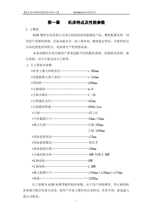
第一章机床特点及性能参数1.1概述6150数控车床是我公司设计制造的高性能数控产品,整机配置本着一切为用户设想的原则,具备功能齐全,加工效率高,精度稳定性好,可靠性高且自动化程度高等特点,是高效生产的理想设备。
本系列数控车床可据用户要求选配不同的数控系统、伺服驱动系统、液压系统、动力卡盘及动力刀架等。
1.2主要技术参数*床身上最大回转直径………………………ø 500mm*过拖板最大加工直径………………………ø 210mm*顶间距………………………………………1500mm-5*主轴端部……………………………………A2*主轴头锥孔…………………………………1∶20*主轴通孔直径………………………………ø82mm*主轴最高转速………………………………2000r/min*刀架…………………………………………四工位*刀具截面尺寸………………………………25mm×25mm*最大行程……………………………………X轴:250mmZ轴:1500mm*尾座套筒直径………………………………ø75mm*尾座套筒锥孔………………………………莫氏5#*尾座套筒行程………………………………150mm*主轴电机功率………………………………4KW/伺服5.5KW*X轴电机……………………………………1KW*Z轴电机……………………………………1.5KW*最大轮廓尺寸………………………………1760mm×1190mm×1470mm*重量…………………………………………2200kg以上参数为6150标准型数控机床参数。
由于用户的特殊性,您订购的机床参数可能会有部分改变,请用户在加工操作时认真核对,若有不清,请迅速与我公司联系。
第二章机床的吊运与安装2.1开箱用户在收到机床后应尽快打开包装箱检查,检查过程中应特别注意以下项目:a.检查整机包装是否完整?b.机床在运输过程中是否受潮?c.检查机床外观及各部件是否在运输过程中受损?d.按《发货清单》进行清查,是否有与《发货清单》不符合的地方。
CA6150设备操作规程3

CA6150卧式车床设备操作规程一、主要参数:1、最大工件回转直径为Φ500mm、最大工件长度为2000mm;2、主轴内锥孔为莫氏6号,主轴通孔直径为Φ52;3、主轴转速级数为24级,范围为9~1600r/min;4、主电机功率为7.5kw,快速移动电机功率为0.25kw。
二、操作前准备1、正确穿戴劳动防护用品。
系紧袖口、领口、下摆口;佩戴好护目镜。
2、检查操作手柄、开关、旋钮是否在正确位置,操纵是否灵活,刹车是否灵敏,刀架、尾座等是否锁紧,安全装置是否安全、可靠,床头箱等旋转部位护罩是否完好可靠。
3、检查确认卡盘等夹具、卡具的防松脱装置是否完好可靠。
4、在刀架中托板、道轨、尾座加润滑油,空跑几个回程,使润滑油与接触面充分结合。
5、接通电源,空车低速运转2-3分钟,并观察运转情况是否正常,查看电机、油泵。
如有噪音异味应停机检查或报告维修人员。
6、检查脚踏板是否完好、稳固、无油污,防止操作人员在脚踏板上移动时踩空、滑倒造成伤害三、操作步骤1、根据要加工的零件图选择安全、可靠的吊具和装夹方法。
2、选择合适刀具,刀具刃尽量与卡盘中心持平,刀杆不宜伸出过长。
3、按照工艺卡要求选择合理的切削三要素。
4、启动电源开关,开车,完成切削后停车。
5、清理铁切屑。
完全停车后用专用清理工具进行切削清理。
6、测量、卸工件。
在测量之前,把各手柄放置零位,防止测量时,突发异常。
测量后,量具放回工作台面。
测量合格后,卸下工件,平稳放置货架上。
7、收尾。
将各操作手柄置于停机位置,尾座、溜板箱移至床身右端,切断电源。
用专用工具清理床身、刀架、脚踏板铁屑,清扫作业场地铁屑。
清扫时,防止铁屑迸溅,造成对人员的伤害。
四、注意事项1、操作者禁止私自打开传动箱,在维修中需要打开箱体时,应先将车床断电。
2、车床皮带罩具备开门断电功能,在车床运转时应将皮带罩关好。
3、车床存在工件旋转、刀具划伤、铁屑烫伤、运动部件挤压、切削液飞溅等危险,操作者在使用车床前应经过技能培训。
6150数控车床技术参数
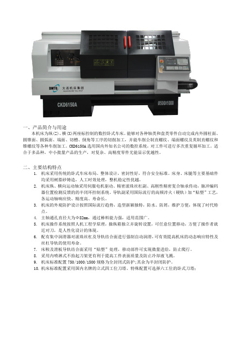
一、产品简介与用途本机床为纵(Z)、横(X)两座标控制的数控卧式车床。
能够对各种轴类和盘类零件自动完成内外圆柱面、圆锥面、圆弧面、端面、切槽、倒角等工序的切削加工,并能车削公制直螺纹、端面螺纹及英制直螺纹和锥螺纹等各种车削加工。
CKD6150A选用国内外知名公司的数控系统,对工件可进行多次重复循环加工。
适合于多品种,中小批量产品的生产,对复杂、高精度零件尤能显示优越性。
二、主要结构特点1.机床采用传统的卧式车床布局。
整体设计,密封性好,符合安全标准。
床身、床腿等主要基础件均采用树脂砂铸造,人工时效处理,整机稳定性优越。
2.机床纵、横向运动轴采用伺服电机驱动、精密滚珠丝杠副、高刚性精密复合轴承传动,脉冲编码器位置检测反馈的的半闭环控制系统。
导轨副采用国际流行的高频淬火(硬轨)加“贴塑”工艺,各运动轴响应快、精度高、寿命长。
3.机床的外观防护设计按照国际流行趋势,造型新颖独特,防水、防屑,维护方便;体现了时代特点。
4.主轴通孔直径大为Φ82mm,通过棒料能力强,适用范围广。
5.机床操作系统按照人机工程学原理,操纵箱独立并旋转设置,可任意位置移动,方便了操作者就近对刀,是人性化设计的体现。
6.配有集中润滑器对滚珠丝杠及导轨结合面进行强制自动润滑,可有效提高机床的动态响应特性及丝杠导轨的使用寿命。
7.床鞍及滑板导轨结合面采用“贴塑”处理,移动部件可实现微量进给,防止爬行。
8.采用内喷淋式不抬起刀架更有利于提高工件表面质量及防止冷却液飞溅。
9.机床标准配置750/1000/1500规格为全封闭式防护;其余为半封闭防护。
10.机床标准配置采用国内名牌的立式四工位刀塔。
特殊配置可选择六工位的卧式刀塔;三、主要技术参数1. 技术规格床身上最大工件回转直径≥φ500 mm刀架上最大工件回转直径≥φ280 mm最大工件长度≥1000mm最大加工长度≥930 mm最大车削直径≥φ500 mm主轴中心高≥250 mm床身导轨宽度≥400 mm2. 主传动标准配置主电动机(双速电机)≥6.5/8Kw主轴通孔直径≥φ82 mm主轴孔锥度前端Ф90mm 1:20主轴头≥C8主轴前端轴承内径≥φ120mm主轴转速范围≥35~1600 r/min3. 尾座装置•• 尾座套筒直径≥φ75mm尾座套筒行程≥150 mm尾座套筒锥孔锥度莫氏5号4.进给系统刀架最大行程横向(X) ≥280 mm••• 纵向(Z) ≥935mm滚珠丝杠直径×螺距横向(X)≥φ20×4 (mm)纵向(Z)≥φ40×6 (mm)••• 横向切削力(连续)横向(X)≥2500 N’••••纵向切削力(连续)纵向(Z)≥5000 N横向快速进给≥4000mm/min 纵向快速进给≥8000mm/min 切削进给范围≥0.01~500mm/r定位精度横向(X)≤0.03 mm纵向(Z)≤0.040mm(<500~1000)≤0.045mm(<1000~1500)≤0.050mm(≥1500)重复定位精度横向(X)≤0.012 mm纵向(Z)≤0.016mm(<500~1000)≤0.020 mm(<1000~1500)≤0.025 mm(≥1500)工件加工精度≤IT6~ IT7工件表面粗糙度≤Ra1.65.刀架装置标准配置:电动立式四工位刀架刀架电机功率≥180 W转速≥1500 r/min 刀杆截面25×25 mm重复定位精度≤0.008 mm换刀时间 (单工位) ≤3s6. CNC控制系统FANUC 0i Mate-MD数控系统,具有完善可靠的联锁、安全保护和故障自诊断报警等功能。
- 1、下载文档前请自行甄别文档内容的完整性,平台不提供额外的编辑、内容补充、找答案等附加服务。
- 2、"仅部分预览"的文档,不可在线预览部分如存在完整性等问题,可反馈申请退款(可完整预览的文档不适用该条件!)。
- 3、如文档侵犯您的权益,请联系客服反馈,我们会尽快为您处理(人工客服工作时间:9:00-18:30)。
第一章机床特点及性能参数1.1概述6150数控车床是我公司设计制造的高性能数控产品,整机配置本着一切为用户设想的原则,具备功能齐全,加工效率高,精度稳定性好,可靠性高且自动化程度高等特点,是高效生产的理想设备。
本系列数控车床可据用户要求选配不同的数控系统、伺服驱动系统、液压系统、动力卡盘及动力刀架等。
1.2主要技术参数*床身上最大回转直径……………………… 500mm*过拖板最大加工直径……………………… 210mm*顶间距………………………………………1500mm*主轴端部……………………………………A2-5*主轴头锥孔…………………………………1∶20*主轴通孔直径………………………………82mm*主轴最高转速………………………………2000r/min*刀架…………………………………………四工位*刀具截面尺寸………………………………25mm×25mm*最大行程……………………………………X轴:250mmZ轴:1500mm*尾座套筒直径………………………………75mm*尾座套筒锥孔………………………………莫氏5#*尾座套筒行程………………………………150mm*主轴电机功率………………………………4KW/伺服*X轴电机……………………………………1KW*Z轴电机……………………………………*最大轮廓尺寸………………………………1760mm×1190mm×1470mm*重量…………………………………………2200kg以上参数为6150标准型数控机床参数。
由于用户的特殊性,您订购的机床参数可能会有部分改变,请用户在加工操作时认真核对,若有不清,请迅速与我公司联系。
第二章机床的吊运与安装开箱用户在收到机床后应尽快打开包装箱检查,检查过程中应特别注意以下项目:a.检查整机包装是否完整b.机床在运输过程中是否受潮c.检查机床外观及各部件是否在运输过程中受损d.按《发货清单》进行清查,是否有与《发货清单》不符合的地方。
我公司对机床的保修期为一年,以出厂之日算起,若用户在开箱时发现问题,请速与我公司以及机床的代理商进行联系,以便能尽快解决问题。
1.2机床的吊运吊运带包装箱的机床,应按包装上的标志符号套系钢索,在起吊、卸放时应特别注意,不应使机床受到冲击和剧烈震动,吊运过程中不应过度倾斜,更不允许侧置或倒置机床。
搬运拆箱后的机床,应首先查看《机床外形及安装基础图》。
本公司推荐用户使用合适的叉车进行机床的搬运。
安装场地要求本机由多组垫铁支承,对于地基推荐采用整体式,其地基深度应大于500mm。
同时机床不应放在有太阳光线直射的地方,设备周围不应有粉尘、水、油或振动。
推荐环境温度:5~35℃推荐湿度:75%相对湿度电源要求我公司推荐用户采用独立电源,防止其它电气设备带来的电流、电压波动使机床出现故障。
机床要求有独立的接地点,且要求接地线尽可能地粗。
第三章机床试运行2.1准备工作试运行前应完成以下工作:a.彻底清除设备上的防锈油。
b.确定设备的所有螺钉都已紧固。
c.确定设备的液压油箱(带液压系统机床)、润滑油箱等已加满。
上电试运行机床上电后应先逐项检查以下项目:a.各冷却风扇是否工作正常b.机床油路是否通畅是否有漏油现象c.检查各压力表是否工作正常(带液压系统机床)d.机床的润滑系统是否已经开始工作e.机床各个运转部件中的皮带其张紧力是否合适确定以上各项均正常工作时,方可分别对以下各部件进行试运行。
a.主轴系统机床主轴系统应首先完成从低速到高速的运转,推荐用户按机床最高转速的10%运行主轴,然后每次增加最高转速的10%,直至机床最高转速,各个转速段运转时间不得少于二十分钟。
检查主轴部件在运转过程中是否平稳、顺畅;检查主轴部件在运转过程中是否有异响发出。
b.进给系统在机床润滑系统工作正常的情况下,可先在手动模式下移动拖板,让拖板及滑板触及各个限位开关,确认每一个限位开关都有效;检查整个移动部件在X向、Z向是否移动顺畅。
c.刀架系统确认刀架上各刀具安装正确后,检查是否会与机床其它部件发生干涉,确定安全后可通过换刀指令运转刀架。
检查整个刀架部件是否运转平稳、顺畅;换刀是否完全到位。
d.尾座系统松开尾座锁紧手柄及尾座套筒锁紧手柄,移动尾座及尾座套筒。
检查尾座部件各个运动机构是否移动顺畅;检查尾座部件各个锁紧手柄是否有效。
本机床已为用户设立了各项安全防护,但用户在操作时仍必须认真执行说明书上各项要求,同时在完成本章工作前必须认真阅读《操作说明书》其各种要求,规定应同时执行!第四章机床的水平调整用户在完成机床的试运行后应对机床进行水平调整,因为水平是机床整机所有精度的最初基准,只有完成水平调整才能保证机床最终的加工精度。
用户可按以下步骤调整机床水平。
a.逐个调节每个地脚螺钉及垫铁,使机床在无明显偏重的情况下,让每一个垫铁基本上受力均匀。
b.在床身导轨面上安放水平仪支架,或直接将水平仪支架稳固于滑板上并将水平仪置于水平仪支架上。
c.等距离(近似等于规定的局部误差的测量长度)移动水平仪支架或机床拖板,在每个测量点上观察水平仪读数,同时认真仔细地逐个调整相应地脚螺钉及垫铁。
d.重复以上步骤直至水平读数达到规定要求。
(具体要求请核对机床精度检验表或机床附带的《合格证明书》)e.锁紧全部地脚螺钉。
请用户注意,随着机床的使用时间加长,机床的水平可能会发生改变,故推荐用户每年至少对机床水平进行一次复查。
另外,若在使用过程中发生较大事故如:撞车、外力冲撞机床等,则要求用户必须对机床水平进行复查。
第五章主轴系统特点简介本机主轴为独立主轴单元,由电机经皮带直接带动主轴,无级变速。
本机主轴系统具有良好的精度、刚性及热稳定性,主轴轴承全部经仔细调整固定在最佳预紧状态,同时采用专用轴承润滑脂使主轴温升最低,热变形最小。
本机主轴单元为全封闭式,无任何调整装置。
机床在使用过程中可以做到不需日常维护也无需操作及维修人员进行加注润滑油等保养工作。
机床超过十天以上的停机用户必须按【第三章机床试运行】步骤运行主轴系统!由于用户根据自己的加工要求选用不同的夹具,这可能会使主轴转速受到损失进而降低工作转速,请用户在使用中认真选择所用的转速范围,否则将导致重大事故发生。
用户至少应征得我公司同意方可自行拆、修主轴,否则我公司不推荐用户自行对主轴进行拆、修、调整。
主轴系统的结构及调整皮带张紧主轴皮带在机床出厂时已调整至最佳状态,因皮带属易损件,经长时间工作后,其张紧力会发生变化,以至出现被拉长甚至断裂的情况,用户可按下列步骤重新装调皮带:a.松开主电机连接板上的全部锁紧螺钉;b.移动电机及电机连接板及后装入新皮带;c.左右移动电机及电机连接板使皮带张紧力合适;d.紧固全部锁紧螺钉。
皮带张紧力过大会加速皮带及相关轴承的磨损;张紧力过小则降低皮带的传递扭矩,使机床达不到使用要求。
我公司要求用户定期检查皮带的张紧,在张紧力不合适时应立即进行调整。
主轴调整图中所示的圆螺母即是用来调整前后轴承时使用,圆螺母外圆上分布有锁紧螺钉,松开螺钉,通过转动圆螺母来调整主轴。
主轴一经调整必须进行中、高速空转试验,使温升及各项精度指标达到规定要求。
加工中若出现撞车等重大事故,用户应立即复查主轴系统的各项精度,若有任何问题请速与我公司联系。
因主轴系统属于精密部件,用户至少应征得我公司同意同时在我公司专业技术人员指导下方可拆、修及调整主轴,否则我公司不推荐用户自行对主轴进行拆、修、调整。
主轴本机主轴为国标:A2-5号标准主轴头,其主要连接尺寸如下:卡盘普通三爪手动卡盘本机标准配置为:160mm普通三爪手动卡盘,用户应严格按照卡盘的最大、最小夹持范围进行加工使用,否则将会导致严重的事故发生!(参看卡盘说明书)用户应根据使用情况定期对卡盘进行保养。
(参看卡盘说明书)高速三爪手动卡盘(选件)高速三爪手动卡盘其结构与普通三爪手动卡盘基本一致,但在性能上有较大差异,本机附带生产厂商说明书,请用户严格按说明书要求进行使用及保养。
动力卡盘及回转油缸(选件)动力卡盘及回转油缸在机床出厂时已调整至最佳状态,用户在使用时应完成以下工作:a.按加工零件的尺寸要求合理安装卡爪;b.按加工零件的尺寸要求配车卡爪;(适用于软爪)c.根据零件的具体情况,调整液压系统中进入回转油缸油路的压力,使得动力卡盘在保证零件不发生夹持变形的前提下具有最大的夹持力。
(进入回转油缸油路的最大压力及动力卡盘最大的夹持力应按《动力卡盘及回转油缸说明书》中要求进行标定。
)由于用户要求使用的卡盘及回转油缸种类较多,本说明书在此不作过多说明,用户应参阅本机附带的生产厂商卡盘及回转油缸说明书,严格按其具体使用方法及维修保养说明进行加工及保养。
用户在使用一段时间后应对动力卡盘及回转油缸进行调整、维修保养,建议用户最好在我公司的专业人员指导下完成该项工作。
用户在使用中应严格遵守卡盘的极限转速要求,严格限制用户不得在卡盘极限转速以上使用该卡盘进行运转及加工!请用户注意,本机床最高转速指定为不装配任何卡盘时的主轴转速,用户在加工时可使用的实际最高转速应是卡盘的最高转速同时不得超过本机床最高主轴转速!第六章尾座系统特点简介本机尾座为手动尾座,尾座带有套筒锁紧和尾座体锁紧两个手柄以及用于控制尾座套筒伸出或退回的手轮。
在使用过程中,用户可根据机床的加工区域和零件具体情况,方便地移动尾座或尾座套筒,使其处于最好的加工位置。
为了保证加工的安全、可靠,机床在使用时应检查尾座的锁紧装置及锁紧力均已调整至最佳状态。
锁紧与移动用户需对尾座及尾座套筒进行锁紧与移动时,可参照以下步骤:a.松开套筒锁紧手柄,转动手轮,即可伸出或退回尾座套筒。
完全退回尾座套筒可以方便地取出安装在套筒内锥中的顶尖、心轴等机床工具或附件。
尾座套筒内还装有水平方向的锁紧扁尾,便于用户安装带扁尾的各类钻帽、铰刀、钻头等机床工具或附件。
b.松开尾座锁紧手柄,即可沿床身导轨方向移动尾座。
尾座体锁紧力调节在尾座底部压板下,用户可根据加工要求调节两个M16螺母的位置,改变尾座锁紧力以保证加工要求。
尾座体套筒中心位置调节尾座套筒中心的调整可利用装在尾座两边的定位螺钉来进行,由于出厂时尾座套筒中心已调至标准范围内,因此,这种调整仅用于消除(主轴)顶尖对(尾座套筒)顶尖间的对准偏差的场合。
另外当机床用于加工较小斜度时,也可借助以上的调整来完成。
用户在使用一段时间后应对尾座体顶部的油杯中加注润滑脂进行必要的维修保养。
本机标准配置为四工位电动刀架,用户在使用中应注意以下几点:a.在保证不与机床防护罩、尾座及车头端面板发生干涉的情况下正确安装刀具。
b.使用中,应根据加工需要合理分布刀具,避免刀架受力不均及长期局部磨损影响使用寿命。
c.在机床保修期内,我公司不推荐用户以任何方式自行拆、修刀架。