PixHawk下载与编译Bootloader文件
WIZ200WEB 用户手册说明书
Document History InformationRevision Data DescriptionVer. 1.0 2008. 12. Release with WIZ200WEB launching23WIZnet’s Online Technical SupportIf you have any questions or want more information about WIZnet products, submit your question to the Q&A Board on the WIZnet website.(www.wiznet.co.kr) A WIZnet engineer will have an answer for you as soon as possible.4Table of Contents1. Introduction ......................................................................................................................................... 7 1.1. Main Function .........................................................................................................................................................7 1.2. Specification ............................................................................................................................................................8 1.3.Contents (WIZ200WEB-EVB) (8)2. Block Diagram ..................................................................................................................................... 93. WIZ200WEB Base Board .................................................................................................................. 114. Getting Started .................................................................................................................................. 16 4.1.Configuration Tool (16)4.1.1. Basic Configuration .................................................................................................................................. 16 4.1.2. Firmware Upload ....................................................................................................................................... 17 4.1.3. Webpage Upload ...................................................................................................................................... 19 4.1.4. Use of Rom File Maker rev3.0 .. (20)4.2.Operation Test (22)4.2.1. Hardware Interface ................................................................................................................................... 22 4.2.2.Testing the Function of Web Server (23)5. Programmer’s Guide ........................................................................................................................ 26 5.1. Memory Map ....................................................................................................................................................... 26 5.2. WIZ200WEB Firmware ................................................................................................................................... 26 5.3. Compile .................................................................................................................................................................. 28 5.4.Downloading (28)6. WIZ200WEB Hardware Specification ............................................................................................ 31 6.1. Parameters ............................................................................................................................................................ 31 6.2. Specification ......................................................................................................................................................... 31 6.3.Board Dimensions and Pin Assignment (31)6.3.1. Pin Assignment .......................................................................................................................................... 31 6.3.2. Size .................................................................................................................................................................. 32 6.3.3.Connector Specification (33)7. Warranty (35)5TablesTable 1. WIZ200WEB Specification .................................................................................................................8 Table 2. Contents of WIZ200WEB ...................................................................................................................9 Table 3. WIZ200WEB PIN MAP ..................................................................................................................... 12 Table 4. Expansion Connector ....................................................................................................................... 15 Table 5. WIZ200WEB Testing Environment .............................................................................................. 22 Table 6. WIZ200WEB Main Source .............................................................................................................. 27 Table 7. WIZ200WEB PINMAP .. (31)6FiguresFigure 1. Block Diagram .................................................................................................................................. 10 Figure 2. WIZ200WEB Base Board Layout ............................................................................................... 11 Figure 3. AVR JTAG Connector...................................................................................................................... 12 Figure 4. AVR ISP Connector ......................................................................................................................... 12 Figure 5. WIZ200WEB PIN MAP ................................................................................................................... 12 Figure 6. WIZ200WEB LED .............................................................................................................................. 13 Figure 7. WIZ200WEB Switch ........................................................................................................................ 13 Figure 8. WIZ200WEB 16x2 LCD .................................................................................................................. 14 Figure 9. WIZ200WEB VR ................................................................................................................................ 14 Figure 10. WIZ200WEB T emperature Sensor .......................................................................................... 15 Figure 11. Configuration T ool ....................................................................................................................... 16 Figure 12. Board Search Window ................................................................................................................ 18 Figure 13. Open dialog box for uploading ............................................................................................. 19 Figure 14. Firmware uploading window ................................................................................................... 19 Figure 15. Complete Uploading ................................................................................................................... 19 Figure 16. Flash Rom Image File .................................................................................................................. 20 Figure 17. ROM File Maker ............................................................................................................................ 21 Figure 18. ROM Image File Make ................................................................................................................ 21 Figure 19. WIZ200WEB External Interface ................................................................................................ 22 Figure 20. WIZ200WEB index page ............................................................................................................ 23 Figure 21. WIZ200WEB Digital Output Page .......................................................................................... 24 Figure 22. WIZ200WEB Digital Input Page .............................................................................................. 24 Figure 23. WIZ200WEB Analog Input Page ............................................................................................. 25 Figure 24. WIZ200WEB Memory Map ....................................................................................................... 26 Figure 25. AVR Studio ...................................................................................................................................... 28 Figure 26. ATmega128 ISP .............................................................................................................................. 29 Figure 27. WIZ200WEB Boot Loader Program ....................................................................................... 30 Figure 28. WIZ200WEB Pin Map .................................................................................................................. 31 Figure 29. WIZ200WEB Module Dimension ............................................................................................ 32 Figure 30. WIZ200WEB Base Board Size................................................................................................... 33 Figure 31. RJ-45 PIN Assignment ................................................................................................................ 33 Figure 32. RJ-45 PIN Assignment ................................................................................................................ 34 Figure 34. RS-232 PIN Assignment . (34)71. IntroductionWIZ200WEB provides the tiny embedded web server operating on low-speed MCU. It controls digital output or monitors digital and analogue input through web browser. The webpage is stored in the serial flash memory of the board, and can be updated through network.1.1. Main FunctionOperates as HTTP ServerGuarantee system stability and reliability by using W5300, the hardwired chip Provides Configuration Tool Program for easy control and confiuration Supports 10/100 Mbps Ethernet RoHS Compliant81.2. SpecificationITEMDescriptionMCUATmega128(having internal 128K Flash, 4K SRAM, 4K EEPROM, external 32K SRAM, 512K Serial Flash)ProtocolsTCP/IP - W5300 (Ethernet MAC & PHY Embedded)UDP – Configuration HTTP Server DHCPNetwork Interface 10/100 Mbps Auto-sensing, RJ-45 Connector Input Voltage DC 5V Power ConsumptionUnder 180mATemperature 0°C ~ 80°C (Operation), -40°C ~ 85°C (Storage) Humidity10 ~ 90%Table 1. WIZ200WEB Specification1.3. Contents (WIZ200WEB-EVB)WIZ200WEB ModuleWIZ200WEB Base Board9CD (Configuration Tool Program, Firmware, Manual areincluded)LAN Cable5V Power AdaptorTable 2. Contents of WIZ200WEB☞ If any missing item is found, contact to the shop you purchased.2. Block Diagram10Figure 1. Block DiagramThe main MCU of WIZ200WEB is 8 bit AVR (ATmega128). The Ethernet is processed by W5300, the hardwired TCP/IP chip. When connected to the IP address of the board at the web browser, the webpage in the serial flash memory is transmitted and displayed. Each webpage enables controlof digital input & output, analogue input and network configuration on the web.3. WIZ200WEB Base BoardWIZ200WEB module can be tested by using base board.11Figure 2. WIZ200WEB Base Board Layout①PowerThe power can be controlled by using power switch after connecting the DC 5V (500mA)adaptor.②ATmega128 JTAG ConnectorFigure 3. AVR JTAG Connector12③ATmega128 ISP ConnectorFigure 4. AVR ISP Connector④WIZ200WEB Module ConnectorThe connector has below pin map.Figure 5. WIZ200WEB PIN MAPJ3 J23.3V 3.3V ADC0/PF0 ADC1/PF1GND GND ADC2/PF2 ADC3/PF3SCL/INT0/PD0 SDA/INT0/PD1 ADC4/PF4 ADC5/PF5RXD1/INT2/PD2 TXD1/INT3/PD3ADC6/PF6 ADC7/PF7ICP1/PD4 XCK1/PD5 AREF PB4T1/PD6 T2/PD7 PB5 PB6SS/PB0 SCK/PB1 PB7 PE7MOSI/PB2 MISO/PB3 PE5 PE6RXD0/PE0 TXD0/PE1 PE3 PE4GND GND /RESET PE2Table 3. WIZ200WEB PIN MAP13⑤ Serial Connector(UART0)The debugging information is transmitted through Serial connector when proceeding development.⑥ Serial Connector(UART1)The debugging information is transmitted through Serial connector when proceeding development. ⑦ LED4 LEDs are installed in the WebServer Base Board, and connected to PORTB.4~7. .Figure 6. WIZ200WEB Base Board LED⑧ System Reset Switch⑨ SwitchSwitch is connected to PORTE.5~6. It is the slide switch.Figure 7. WIZ200WEB Base Board Switch⑩ 16X2 character LCD16x2 LCD is controlled with the method of 4 bit control It is connected to PORTD andPORTE.14Figure 8. WIZ200WEB Base Board 16x2 LCD⑪Variable ResistorIn order to test the analog data easily, you can use variable resistor and get the input valueof analog variable. Variable resistor is connected to ADC0 channel.Figure 9. WIZ200WEB Base Board VR⑫Digital Temperature SensorMicrochip’s TC77 having 12bit resolutions is used for temperature sensor. Temperaturesensor can be controlled by SPI and selected through PB0.Figure 10. WIZ200WEB Base Board Temperature Sensor15⑬Extension ConnectorIt is the connector (J12) to extend to GPIO and the function pins of ATmega128NO FUNCTION NO FUNCTION1 NC2 5V3 NC4 GND5 SCL/INT0/PD06 ADC0/PF07 SDA/INT0/PD1 8 ADC1/PF19 RXD1/INT2/PD2 10 ADC2/PF211 TXD1/INT3/PD3 12 ADC3/PF313 ICP1/PD4 14 ADC4/PF415 XCK1/PD5 16 ADC5/PF517 T1/PD6 18 ADC6/PF619 T2/PD7 20 ADC7/PF721 SS/PB0 22 AREF23 SCK/PB1 24 PE725 MOSI/PB2 26 PB627 MISO/PB3 28 PE529 PB4 30 PE431 PB5 32 PE333 PB6 34 PE235 PB7 36 /RESET37 PE1/TXD0 38 NC39 PE0/RXD0 40 NCTable 4. Expansion Connector4. Getting Started4.1.Configuration Tool4.1.1.Basic Configuration16Figure 11. Configuration T oolⓐVersion : It displays Firmware version.ⓑ Board List : If “Search” button is clicked, all MAC address of WIZ200WEB modules are displayed in the Board List.ⓒLocal IP/Port : IP Address of WIZ200WEBⓓSubnet : Subnet Mask of WIZ200WEBⓔGateway : Gateway Address of WIZ200WEBⓕ Web Page Upload : It is possible to upload ROM Image file to the internal flash memory ofWIZ200WEB. For the detail, refer to “4.1.3. Webpage Upload”.ⓖEnable DHCP Mode : It is the option for DHCP mode. Select a MAC Address to be used for17‘Enable DHCP mode’ at the ‘board list’. If you click “Setting” button, the board acquires IP and Subnet Mask by using DHCP . (By acquiring IP address from DHCP server, it can take some time) After acquiring network information from DHCP , re-booting is processed. If you click “Search” button again, you can check changed values. If you click MAC Address on the ‘Board list’, IP Address, Subnet Mask and Gateway information are displayed. If network information is not acquired due to any problem, IP , Subnet and Gateway Address are initialized to 0.0.0.0.ⓗ Search : “Search” function is used for searching module on the same LAN. If all the modules on the same subnet are searched by using UDP broadcast, their MAC addresses are displayed on the “Board List”.ⓘ SettingThis function is used for changing the configuration values of WIZ200WEB. After changing any configuration value, “Setting” button should be clicked for applying the value. With this, the values can be saved in the EEPROM and maintained even after shutting down the power of module. The process is as below.① Select a MAC address at the “Board list”. The configuration values of selected module aredisplayed in each field. ② Change the value of each field.③ If you click “Setting” button, the configuration is completed.④ The module is initialized with the changed configuration. (automatically re-booted) ⑤ In order to check changed value, search the module with “Search” button.ⓙ UploadFirmware is uploaded through network.Firmware upload process is described in detail at the “4.1.2 Firmware Upload” ☞ The initialization takes about 20~30 seconds after uploading the firmware.ⓚ Exit : It closes Configuration tool program.4.1.2. Firmware Upload① Execute Configuration Tool program and click ‘Search’ button.② If the module is correctly connected to the network, its MAC address is displayed on the ‘Board list’.18Figure 12. Board Search Window③Select a module at the ‘Board list’ and click ‘Upload’ button.☞ Before uploading through Ethernet, the network information should be set for correct network communication. By using PING test, it is possible to check if the value is appropriate for network communication.④As below dialog box is shown, select the Binary file and click ‘OPEN’ button.19Figure 13. Open dialog box for uploading☞ Be sure to use the firmware only for WIZ200WEB.⑤You can see below status window showing ‘Processing’.Figure 14. Firmware uploading window⑥If the file is uploaded, ‘Complete Uploading’ message is displayed.Figure 15. Complete Uploading4.1.3.Webpage Upload①Execute Configuration Tool program and click ‘Search’ button.②If the module is correctly connected to the network, its MAC address is displayed on the20‘Board list’.③ Select the board at the ‘Board list’ and click ‘web page Upload’ button.☞ Before uploading through Ethernet, the network information should be set for correct network communication. By using PING test, it is possible to check if the value is appropriate for network communication.④ As below dialog box shows, select the Flash Rom File System (*.rom) file and click ‘OPEN’ button.Figure 16. Flash Rom Image File☞ The Flash Rom File System should be created by using “Rom File Maker Tool rev3.0”. For the detail, refer to “4.1.4. Use of Rom File Maker rev3.0”⑤ If the file is uploaded, ‘Complete Uploading’ message is displayed.4.1.4. Use of Rom File Maker rev3.0Rom File Maker rev3.0 is the tool for creating ROM Image which enables the webpage to be stored in the Flash memory.Select the webpage by using ‘Add Files’ button.☞ There is limitation of file number in selecting at a time. (Normally, max 15 files can be selected simultaneously). If there are more files, use “Add Files” button for the several times.21Figure 17. ROM File MakerSelect ‘Rom Image File’ option. If you click ‘Make Image’ button, ‘*.rom’ file can be created.Figure 18. ROM Image File Make224.2. Operation TestIn this chapter, we will show how WIZ200WEB operates through a sample testing. The hardware and software requirements for testing are as below.PCWIZ200WEBHardware1) LAN Port1) WIZ200WEB Board 2) LAN Cable3) DC5V Power AdaptorSoftware1) Configuration Tool Program 2) Web BrowserTable 5. WIZ200WEB Testing Environment4.2.1. Hardware InterfaceFigure 19. WIZ200WEB External InterfaceHardware installation process is as below.STEP 1: By using RJ45 Ethernet cable, connect the board to the network.Serial CableLAN CablePower23STEP 2: Connect 5V DC adaptor to WIZ200WEB board.4.2.2. Testing the Function of Web ServerSTEP1: Supply the power to WIZ200WEB board.STEP2: Configure the board by using Configuration Tool.STEP3: Execute the web browser and input the IP address of the WIZ200WEB to access the webpage.STEP4: If connection is appropriately processed, ‘index.html’ page is displayed on the web browser.Figure 20. WIZ200WEB index pageSTEP5: Click ‘Digital Ouput’ menu at the web browser, and control the LED and LCD installed on the WIZ200WEB Base Board.24Figure 21. WIZ200WEB Digital Output PageSTEP6: Click ‘Digital Input’ menu, and check the status of switch installed on the WIZ200WEB Base Board. Switch status is updated every one second.Figure 22. WIZ200WEB Digital Input PageSTEP7: Click ‘Analog Input’ menu and check the voltage level according to Variable Resistor(VR) which is installed on the WIZ200WEB Base Board. The VR is updated every second.25Figure 23. WIZ200WEB Analog Input PageSTEP8: Click “ T emperature Read” menu and check current temperature by using the temperature sensor, TC77 installed on the WIZ200WEB Base Board.265. Programmer’s Guide5.1. Memory MapThe memory map of WIZ200WEB is composed of 128Kbyte code memory and 64Kbyte data memory. The data memory is composed of internal SRAM and W5300. In addition, 4Kbyte EEPROM is built in AVR. Environment variables of the board are saved in this EEPROM.Below figure shows the system memory map of the test board.Figure 24. WIZ200WEB Memory Map5.2. WIZ200WEB FirmwareThe firmware performs ProcessWebServer, ProcessDhcp and ProcessConfig in the main() Function ProcessWebServer() operates as webserver. It processes HTTP protocol from web browser, reads the web page in the Flash memory, and sends it. ProcessConfig() function processes network related configuration. ProcessDhcp() function does DHCP related functions.ITEM(Folder name) FileFunctionmainmain.c WIZ200WEB F/W main() config_task.c Net Configuration Task dhcp_task.cDHCP Client Management27iinchipiinchip_conf.h System Dependant Definition of W5300 w5300.c w5300 I/O Function socket.cw5300 Socket APIinet dhcp.c Processing DHCP Client Protocol httpd.c Processing HTTP Protocolmcu delay.c Processing the delay of ATmega128 serial.c UART related Functiontimer.c Timer interrupt Process Function types.h AVR Data Type & Global Definition util sockutil.cSocket related Utility Function util.cUtility Functionevbconfig.c Function to configure network related information dataflash.c Function to process Serial Flashevb.c Function to control devices on the board such as LED, Switch & LCDlcd.c Function to process LCD spi.c Function to process SPIromfile.cFunction to process ROM File SystemTable 6. WIZ200WEB Main Source285.3. CompileThe sources mentioned in the Chapter 5.2, are compiled by aligning in the SRC. The firmware compile can be performed by using WINAVR and AVRSTUDIO.Install the WINAVR and AVRSTUDIO in the PC. For the easy working, open the firmware project file "~/main/ex03_webserver/wiz-web.aps” through AVRSTUDIO project file.Check compile setting of Configuration option of ‘Project’ menu. For the setting method, refer to ‘AVR Studio User Guide’.The firmware provided by WIZnet is based on AVR-GCC 3.4.6. In another version, the operation can be abnormal.Figure 25. AVR StudioWhen compile is completed, hex file is created in the folder that user defined before. This file is programmed to ATmega128.5.4. DownloadingFor the Hex file downloading, use AVR Studio and AVR ISP cable.1)Connect the AVRISP cable to J9 of the Base Board.2)Connect the power adaptor and turn on the switch.3)Execute AVRStudio.exe4)Select Atmega128 at the Device section5)Select HEX file at the FLASH section6)Click Program button.For more detail, refer to ‘AVR Tool Guide.pdf’.29Figure 26. ATmega128 ISPIn order to update the firmware through network, the bootloader should be programmed first. Bootloader is written to be input at 0x1E000. For the re-programming the firmware file, removethe Atmega128 and program the ‘Boot.hex’ file. At this time, do not check the option of “Erase Device Before Programming” for not removing the bootloader.30 Figure 27. WIZ200WEB Boot Loader Program316. WIZ200WEB Hardware Specification 6.1. ParametersPower 5V DC, 3.3VDimension 60 x 42 x 14 (L x W x H) Temperature Operating : 0 ~ 80 ℃Ethernet 10/100 Base-T Ethernet (Auto detection)6.2. SpecificationMCUATmega128FLASH 128KByte (MCU Internal) + 512Kbyte(External Serial Flash) SRAM 4KByte (MCU Internal) + 32Kbyte (External) EEPROM4KByte (MCU Internal)6.3. Board Dimensions and Pin Assignment6.3.1. Pin AssignmentFigure 28. WIZ200WEB Pin MapJ3J23.3V 3.3V ADC0/PF0 ADC1/PF1 GNDGNDADC2/PF2 ADC3/PF3 SCL/INT0/PD0SDA/INT0/PD1ADC4/PF4 ADC5/PF5 RXD1/INT2/PD2 TXD1/INT3/PD3ADC6/PF6 ADC7/PF7 ICP1/PD4 XCK1/PD5 AREF PB4 T1/PD6 T2/PD7 PB5 PB6 SS/PB0 SCK/PB1 PB7 PE7 MOSI/PB2 MISO/PB3 PE5 PE6 RXD0/PE0 TXD0/PE1 PE3 PE4 GNDGND/RESETPE2Table 7. WIZ200WEB PINMAP6.3.2.Size32 Figure 29. WIZ200WEB Module Dimension33Figure 30. WIZ200WEB Base Board Size6.3.3.Connector SpecificationRJ45 : Ethernet Port PinoutsFigure 31. RJ-45 PIN Assignment34Pin Signal1 TX+2 TX-3 RX+6 RX-Figure 32. RJ-45 PIN AssignmentRS-232Pin Number Signal Description1 NC Not Connected2 RxD Receive Data3 TxD Transmit Data4 NC Not Connected5 GND Ground6 NC Not Connected7 NC Not Connected8 NC Not Connected9 NC Not ConnectedFigure 33. RS-232 PIN Assignment357. WarrantyWIZnet Co., Ltd offers the following limited warranties applicable only to the original purchaser. This offer is non-transferable.WIZnet warrants our products and its parts against defects in materials and workmanship under normal use for period of standard ONE(1) YEAR for the WIZ200WEB board and labor warranty after the date of original retail purchase. During this period, WIZnet will repair or replace a defective products or part free of charge.Warranty Conditions:The warranty applies only to products distributed by WIZnet or our official distributors.1. The warranty applies only to defects in material or workmanship as mentioned above in 7.Warranty.2. The warranty applies only to defects which occur during normal use and does not extendto damage to products or parts which results from alternation, repair, modification, faulty installation or service by anyone other than someone authorized by WIZnet Inc. ; damage to products or parts caused by accident, abuse, or misuse, poor maintenance, mishandling, misapplication, or used in violation of instructions furnished by us ; damage occurring in shipment or any damage caused by an act of God, such as lightening or line surge.Procedure for Obtaining Warranty Service1. Contact an authorized distributors or dealer of WIZnet Inc. for obtaining an RMA (ReturnMerchandise Authorization) request form within the applicable warranty period.2. Send the products to the distributors or dealers together with the completed RMArequest form. All products returned for warranty must be carefully repackaged in the original packing materials.3. Any service issue, please contact to ***************.kr。
海康威视网络摄像机操作手册 V5.0.3

注意事项提醒用户防范 潜在的伤害或财产 损失危险。
警告: 请使用满足 SELV(安全特低电压)要求的电源,并按照 IEC60950_1 符合 Limited Power Source(受限电源)的额定电压为 5V/12V 直流或 24V 交流电源供电(供电电源的要求详见说明书) 。 如果设备工作不正常,请联系经销商或最近的服务中心,不要以任何方式拆卸或修改设备(未经许可的修改或维修所导 致的问题,责任自负) 。 为减少火灾或电击危险,请勿让本产品受到雨淋或受潮。 本安装应该由专业的服务人员进行,并符合当地法规规定。 应该在建筑物安装配线中组入易于使用的断电设备。 有关在天花板上安装设备的指示:安装后,请确保该连接至少可承受向下 50 牛顿(N)的拉力。
杭州海康威视数字技术股份有限公司|版权所有(C)
3 网络摄像机 . 操作手册
目录
1 网络连接 ............................................................................................................................................................. 4 1.1 有线网络 ................................................................................................................................................. 4 1.2 无线网络 .....................................................................
PIXHACK硬件资料及使用教程
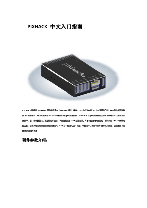
PIXHACK 中文入门指南PIXHACK是根据PIXHAWK硬件架构平台上由CUAV设计,并有CUAV生产的一款32位开源硬件飞控,由于硬件主要架构跟pix完全相同,所以完全兼容3DR APM固件以及pix原生固件。
PIXHACK在pix原版基础上优化了供电芯片,删减不必要接口,接口做调整优化,改为前后方插线。
主要的亮点是IMU分离设计,内置小型通用减震结构,并采用了CNC一体铣成型工艺,抗干扰性还是稳定性都有质的提升。
Pixhack经过Cuav长达一年的设计,无数个版本的优化及测试,已经达到了比较稳定理想的效果:硬件参数介绍硬件参数介绍:处理器 1. 32位2M闪存STM32F427 Cortex M4,带硬件浮点处理单元主频:168MHZ,256K RAM2. 32位STM32F103备份协处理器内置传感器Pixhack 采用IMU分离设计,内置通用性减震,一般飞行器不需要做减震处理(如果震动太大及频率过高还需减震)1.L3GD20 3轴数字16位陀螺仪2.LSM303D 3轴14位 加速度/磁强计3.MPU6000 6轴加速度计/磁强计4. MS5611 高精度气压计工作环境及电压温度范围:-5~50度PM传感器工作电压2-6SPM传感器输出电压5.4V 3APWM OUT输入供电电压最高9V(支持高压舵机,而原版Pixhawk不支持高于5.5V的供电)2路电源自动冗余(PM口和PWM OUT口),PM口优先供电,出现故障自动切换到PWM OUT口供电外观尺寸主控尺寸68mmX44mmX15MM 重量:68g数据接口1. 5个UART 1个兼容高电压,2个带有硬件流控制2. 1个CAN3. Spektrum DSM/DSM2/DSM-X卫星接收机兼容输入4. Futaba SBUS兼容输入和输出5. PPM信号输入6. RSSI(PWM或者电压)输入7. I2C协议设备扩展8. 预留SPI接口9. 3.3和6.6VADC输入10. 外部MICRO USB接口11. 13个PWM/舵机输出12. 多音蜂鸣器及解锁按键 状态led 接口外围设备支持固定翼多旋翼直升机车船固件支持支持接收机类型接收机类型S-Bus, DSM2,PPM 。
Bootloader编译与下载

Bootloader编译与下载Bootloader编译与下载3.1 实验目的:完成Bootloader编译与下载。
3.2 实验内容:参照指导书给出的步骤,一步一步地完成Bootloader编译与下载。
3.3 实验设备:1)硬件环境(硬件连接方法与Android版本一样)设备硬件连接方法必用的设备:串口线一根,网线一根,USB OTG线缆一根。
UART port0 : 作为监测中使用的端口连接串行线。
Ethernet port : 利用 Ethernet,为了高速传送,连接 LAN 线缆。
USB OTG Cable : 利用 USB,为了更新映像时使用,进行连接。
引导模式开关位于试验箱的右下角在下载映像文件之前注意设置引导模式开关设定引导模式NAND Flash 引导模式IROM 引导模式2)软件环境Linux 开发环境- VMWare在XP系统安装虚拟机,通过虚拟机加载一个Linux系统开发环境- Linux内核(CD提供ubuntu 8.04版本)串口监测工具 : minicom开发工具 : 交叉编译器 (CD提供gcc 4.4.1)3.4 实验步骤:操作步骤:提供CD 中“ubuntu_8.04”目录复制到“D:\”目录中。
在这个目录中,双击“ubuntu8.04_android.vmx”文件,运行ubuntu 8.04。
运行Ubuntu 8.04 映像前,需要安装VMware Player 或者WMware Workstation。
出版 CD 中提供了 VMware Player (路径 : tools\vmware-player\VMware-player-3.1.2-301548.exe)。
如果双击“ubuntu8.04_android.vmx”文件,如错误!未找到引用源。
],运行已安装的VMware Player 或者VMware Workstation。
这时,按下 Power On this virtual machine按钮。
PixHawk飞控板烧写BootLoader流程

新的Pixracer飞控是没有Bootloader的,没有Bootloader,就没办法通过控制台给飞控板烧写固件。
因此要先对飞控烧写Bootloader。
本文主要介绍通过JLINK及配套的Flash ISP 软件进行Bootloader烧写的步骤。
1、下载并构建Bootloader。
我是在ubuntu虚拟机上操作的,Windos下没试过。
刚下载下来的问价夹内容如下图所示。
编译过后文件夹如下所示,可以看到增加了很多文件夹,这些文件夹即Bootloader 所在子文件夹:找到飞控对应的文件夹,我用的是px4fmu-v4,故打开biuld_px4fmuv4-bl文件夹,该路径下的px4fmuv4_bl.bin文件即为Bootloader。
2、连接仿真器国内卖JLINK的厂商基本上都是抄人家的,所以自己在使用JLINK时也要以实测为准。
我手上两个JLINK就截然不同。
下图左边的JLINK,第19脚说是5v输出,实测是0。
对于右边的JLINK的,1脚的VTref居然会输出V3.3,所以目标板可以直接以这个为电源来调试。
对于左边的JLINK,目标板必须要提供电源给JLINK的1脚。
且目标板需单独供电。
J-Link接口如下所示,注意缺口方向。
由于本人采用SWD模式下载。
故按照有图所示连接方式。
1,、7、9、20分别连接PIXRACER中控的FMU_VDD_3V3、FMU_SWDIO、FMU_SWCLK、GND等引脚。
3、下载并安装Jlink驱动及Flash ISP软件解压之后如下图所示,安装V486b即可。
下载之后安装即可。
4、烧写Bootloader打开Flash ISP软件开始-->所有程序-->SEGGER-->J-link ARM v4.86b-->J-flash软件打开后出现以下对话框,选择Creat a new project->Start J-flash.J-flash界面如下图所示:点击Options->Project Options,对General、Target Interfice、CPU、Flash等进行设置。
Pixhawk飞控设置飞行模式教程及LED灯意义
飞行模式中文意思:0:Stabilize自稳,1:Acro特技,2:AltHold定高,3:Auto自动,4:Guided引导,5:Loiter留待(常叫悬停),6:RTL返航,7:Circle绕圈,9:Land降落,11:Drift飘移,13:Sport运动,14:Flip翻转,15:AutoTune自动调参,16:PosHold定点,17:Brake暂停M:Copter中有14种飞行模式可供选择,有10种是常用的。
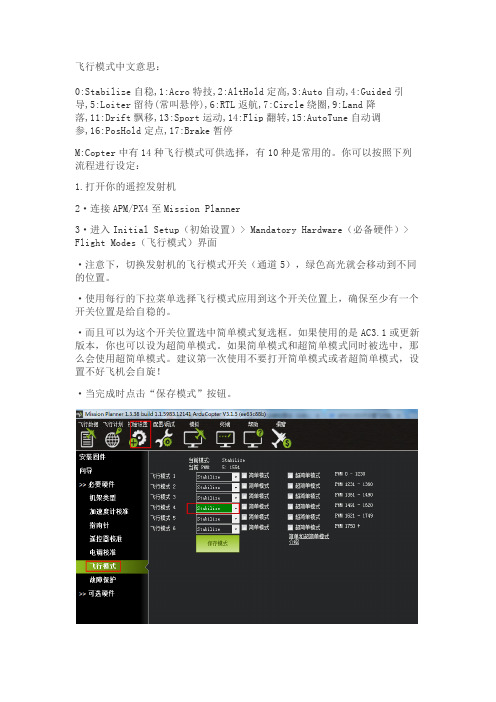
你可以按照下列流程进行设定:1.打开你的遥控发射机2·连接APM/PX4至Mission Planner3·进入Initial Setup(初始设置)> Mandatory Hardware(必备硬件)> Flight Modes(飞行模式)界面·注意下,切换发射机的飞行模式开关(通道5),绿色高光就会移动到不同的位置。
·使用每行的下拉菜单选择飞行模式应用到这个开关位置上,确保至少有一个开关位置是给自稳的。
·而且可以为这个开关位置选中简单模式复选框。
如果使用的是AC3.1或更新版本,你也可以设为超简单模式。
如果简单模式和超简单模式同时被选中,那么会使用超简单模式。
建议第一次使用不要打开简单模式或者超简单模式,设置不好飞机会自旋!·当完成时点击“保存模式”按钮。
飞行模式注解1、稳定模式Stabilize稳定模式是使用得最多的飞行模式,也是最基本的飞行模式,起飞和降落都应该使用此模式。
此模式下,飞控会让飞行器保持稳定,是初学者进行一般飞行的首选,也是FPV第一视角飞行的最佳模式。
一定要确保遥控器上的开关能很方便无误地拨到该模式,应急时会非常重要。
2、比率控制模式Acro这个是非稳定模式,这时apm将完全依托遥控器遥控的控制,新手慎用。
3、定高模式ALT_HOLD定高模式(AltHold)是使用自动油门,试图保持目前的高度的稳定模式。
Huawei DevEco Studio使用指南_鸿蒙学堂

文档内容来自鸿蒙官方网站,鸿蒙学堂 整理
Huawei DevEco Studio 使用指南
2.3 运行 Hello World.........................................................................................................11 3 工程管理......................................................................................................................................14
3.2 支持的设备模板和编程语言 ........................................................................................ 17 3.3 创建一个新的工程.........................................................................................................18
2.2 配置开发环境 ................................................................................................................... 4 2.2.1 npm 设置............................................................................................................. 4 2.2.2 设置 Gradle 代理................................................................................................ 5 2.2.3 设置 DevEco Studio 代理................................................................................ 6 2.2.4 下载 HarmonyOS SDK .................................................................................... 8
长虹说明书
长虹窗式空调使用说明书篇二:长虹白板软件使用说明书长虹白板软件使用说明书用户使用手册(v1.6.3)目录一. 系统特点 ............................................................................. ...............................................................................4二. 系统安装 ............................................................................. ...............................................................................62.1. 运行环境 ............................................................................. . (6)2.2. 系统安装 ............................................................................. . (7)三. 基础操作 ............................................................................. ...............................................................................83.1. 运行程序 ............................................................................. . (8)3.2. 基本操作 ............................................................................. . (9)3.2.1 切换模式 ............................................................................. .. (9)3.2.2 关闭白板软件 ............................................................................. (9)3.2.3 快捷功能区 ............................................................................. .. (10)3.3. 工具条操作 ............................................................................. . (11)3.4. 主要功能 ............................................................................. (12)3.4.1 书写功能 ............................................................................. (12)3.4.2 绘图功能 ............................................................................. (14)3.4.3 工具功能 ............................................................................. (20)3.4.4 背景功能 ............................................................................. (27)3.4.5 管理页面 ............................................................................. (29)3.4.6 素材 ............................................................................. ................................................................................293.4.7 资源 ............................................................................. ................................................................................323.4.8 实验 ............................................................................. ................................................................................353.4.9 题库 ............................................................................. ................................................................................383.5. 对象编辑 ............................................................................. .. (39)3.6. 页面缩放 ............................................................................. .. (42)3.7. 文件功能 ............................................................................. .. (42)3.8. 异常退出自动恢复功能 ............................................................................. (43)前言一、东方中原互动教学支撑系统的介绍东方中原互动教学支撑系统(以下简称东方中原白板软件)可以结合电子白板或液晶平板通过与电脑、投影机,组成一个交互式的协作会议或教学环境,配备的电子笔可代替鼠标和粉笔,在电子白板或液晶平板上书写、绘图、直接操控电脑。
- 1、下载文档前请自行甄别文档内容的完整性,平台不提供额外的编辑、内容补充、找答案等附加服务。
- 2、"仅部分预览"的文档,不可在线预览部分如存在完整性等问题,可反馈申请退款(可完整预览的文档不适用该条件!)。
- 3、如文档侵犯您的权益,请联系客服反馈,我们会尽快为您处理(人工客服工作时间:9:00-18:30)。
PixHawk下载与编译Bootloader文件
购买现成的飞控都是已经烧录好程序的,所以只连接地面站更新固件调试参数就可以了。
但是自己根据官方开源方案设计的PCB就必须烧录引导程序芯片才可以正常工作。
本文以PixHawk(PixFmu2.4.5)为例讲解。
一、安装下载与编译软件PX4 Toolchain
1.1、下载编译文件
进入官网/dev/toolchain_installation_win下载最新安装程序,(这里是以windows操作系统为例,其它系统可以下载对应安装程序)如何下图:
右击目标另存为安装文件。
1.2、安装编译文件
双击安装文件,根据提示安装软件,安装成功后在电脑程序栏处找到PX4 Toolchain
(本例安装版本:px4_toolchain_installer_v14_win),此软件包含以下分支应用,HTerm,PX4 Console,PX4 Eclipse,PX4 Software Download,TeraTerm,Uninstall PX4.
二、下载与编译Bootloader文件
2.1、打开下载软件PX4 Toolchain / PX4 Console软件
2.2、根据提示输入命令(红色字体部分,进入下载网址并下载Bootloader文件,)
Administrator@WIN-09210921 /d/px4
$ git clone https:///PX4/Bootloader.git 回车
完成后,将会在安装文件夹下新建Bootloader文件夹并下载官网相关文件到些文件夹。
2.3、根据提示输入命令(红色字体部分,选择文件夹)
Administrator@WIN-09210921 /d/px4
$ cd Bootloader 回车
2.4、根据提示输入命令(红色字体部分,下载并生成bootloader文件)
Administrator@WIN-09210921 /d/px4/Bootloader
$ make 回车
2.5、根据提示输入命令(红色字体部分,初始化文件)
Administrator@WIN-09210921 /d/px4/Bootloader
$ git submodule init 回车
2.6、根据提示输入命令(红色字体部分,升级文件)
Administrator@WIN-09210921 /d/px4/Bootloader
$ git submodule update 回车
2.7、根据提示输入命令(红色字体部分,下载stylefix文件)
Administrator@WIN-09210921 /d/px4/Bootloader
$ make 回车
注意:以上步骤即可以生成PIX所需要的bootloader文件,官网上提供三个版本的文件可以供下载(master(最新版本),stylefix(合适版本),vetting(通过审核版本)),但是这里默认下载生成的是最新(master版本)的文件。
经过测试,最新版本的文件可能不成熟等原因,会造成飞控可以连接地面站却下载不了固件,又或者可以下载固件却连接不了地面站。
所以要按照以下步骤更新为stylefix(合适版本)。
2.8、更新成stylefix文件
打开下载软件PX4 Toolchain \ PX4 Console,
根据提示输入命令(红色字体部分)
Administrator@WIN-09210921 /d/px4
$ cd Bootloader 回车
2.9、根据提示输入命令(红色字体部分)
Administrator@WIN-09210921 /d/px4/Bootloader
$ git checkout –b stylefix origin/stylefix 回车
2.10、根据提示输入命令(红色字体部分)
Administrator@WIN-09210921 /d/px4/Bootloader
$ make 回车
以上步骤完成生成stylefix版本的bootloader文件
三、下载Firmware文件(主程序源代码)
2.1、运行(主程序源代码)
保存路径(软件安装目录下,自动生成)
Administrator@WIN-09210921 /d/px4
$ git clone https:///PX4/Firmware.git
以上开始下载更新程序(过程约20分钟,具体时间视电脑与网络为准)
四、更新Firmware文件(官网上经常会更新文件)
4.1、根据提示输入命令(红色字体部分)打开Firmware
Administrator@WIN-09210921 /d/px4
$ cd Firmware
4.2、根据提示输入命令(红色字体部分)后回车,初始化更新文件
Administrator@WIN-09210921 /d/px4/Firmware
$ git submodule init
4.3、等以上步骤完成后(约1分钟左右),根据提示输入命令(红色字体部分)后回车Administrator@WIN-09210921 /d/px4/Firmware
$ git submodule update
以上开始下载更新程序(过程约20分钟,具体时间视电脑与网络为准)。