国巨电容规格书
插件国巨电阻规格书
Page-1Approval SheetforCarbon Film ResistorsCFR series±2% & ±5%YAGEO CORPORATIONHeadquarters: 3F, No.233-1, Pao Chiao Rd., Shin Tien, Taipei, Taiwan,R.O.C.Tel: 886-2-2917-7555 Fax: 886-2-2917-4286URL: Page-2Page-31. PRODUCT : CARBON FILM RESISTORS(Normal & Miniature Style)2. PART NUMBER : Part number of the carbon film resistor is identified by the name,power, tolerance, packing, temperature coefficient, special type and resistance value.Example :CFR -12 J T J 52 100RSeries Size Resistance Packing Temperature Special ResistanceName Code Tolerance Style Coefficient Type Value of Resistance(1) Style: CFR SERIES(2) Power Rating: -12=1/6W 、25S=1/4WS 、-25=1/4W 、50S=1/2WS 、-50=1/2W 、 1WS=1WS 、100=1W 、2WS=2WS 、200=2W(3) Tolerance: G=±2% J=±5%(4) Packaging Type : R =Paper Taping Reel T =Tape on Box Packing B =Bulk Packing(5) T .C .R : J=±350ppm/℃ — =lgnore(6) Special Type : 26=26mm 、52=52.4mm 、73=73mm 、 PN =PANAsert AV =AVlsert(7) Resistance Value: 1R 、10R 、100R 、10K 、100K 、330K 、1M………Page-43. BAND-CODE:4. ELECTRICAL CHARACTERISTICSTabe I*Standard resistance is 1Ω~ 10M Ω, below or over this resistance on request. *Rated Continuous Working Voltage (RCWV)=Value Resistance Rating Power ×FIG.1 TEMPERATURE COEFFICIENTPage-55. DERATING CURVE & HOT-SPOT TEMPERATURE6. DIMENSIONS7. ENVIRONMENTAL CHARACTERISTICS(1) Short Time Over Load TestAt 2.5 times of the rated voltage. (If the voltage exceeds the maximum load voltage, the maximum load voltage will be used as the rated voltage) applied for 5 seconds, the resistor should be free from defects after the resistor is released from load for about 30 minutes and the change of the resistance value should be within ±(0.25%+0.05Ω) as compared with the value before the test.Page-6(2) Dielectric Withstanding VoltageThe resistor is placed on the metal V Block. Apply a Table I dielectric withstanding between the terminals connected together with the block for about 60 seconds. The resistor shall be able to withstand without breakdown or flashover.(3) Temperature Coefficient TestTest of resistors above room temperature 125°C to 130°C (Testing Temperature) at the constant temperature silicon plate for over 4 to 5 minutes. Then measure the resistance. The Temperature Coefficient is calculated by the following equation and its value should be within the range of requested.600010t t 1R R R t Coefficien e Temperatur sistor Re ×−×−=R= Resistance value under the testing temperature R 0= Resistance value at the room temperature t = The testing temperature t o = Room temperature(4) Insulation ResistanceApply test terminal on lead and resistor body. The test resistance should be high than 10,000 Mohm.(5) SolderabilityImmerse the specimen into the solder pot at 230±5°C for 5±0.5 seconds. At least 95% solder coverage on the termination.(6) Resistance to SolventThe specimen into the appropriate solvent of Methyleme Chloride condition ofultrasonic machine for 1 minutes. The specimen is no deterioration of coatings and color code.(7) Terminal StrengthDirect Load – Resistors shall be held by one terminal and the load shall be gradually applied in the direction of the longitudinal axis of the resistor unit the applied load reacheds 5 pounds. The load shall be held for 10 seconds. The load of weight shall be ≧2.5kg(24.5N).Page-7(8) Pulse OverloadApply 4 times of rated voltage to the specimen at the 1 second on and 25 seconds off cycle, subjected to voltage application cycles specified in 10000. The change of the resistance value shall be within ±(2%+0.05Ω).(9) Load Life in HumidityPlace the specimen in a test chamber at 40±2°C and 90~95% relative humidity. Apply the rated voltage to the specimen at the 1.5 hours on and 0.5 hour off cycle. The total length of test is 1000 hours. The change of the resistance value shall be within ±(1.5%+0.05Ω).(10) Load Life TestPlaced in the constant temperature chamber of 70±3°C the resistor shall be connected to the lead wire at the point of 25mm. Length with each terminal, the resistors shall be arranged not much effected mutually by the temperature of the resistors and the excessive ventilation shall not be performed, for 90 minutes on and 30 minutes off under this condition the rated D.C. voltage is applied continuously for 1000+48/-0 hours then left at no-load for 1hour, the change of the resistance value measured at this time to the value before the test shall be within ±(1.5%+0.05Ω). There shall be no remarkable change in the appearance and the color code shall be legible after the test.(11) Temperature Cycling TestThe temperature cycle shown in the following table shall be repeated 5 times consecutively. The measurement of the resistance value is done before the first cycle and after ending the fifth cycle, leaving in the room temperature for about 1 hour, the change shall be within ±(1%+0.05Ω). After the test the resistor shall be free from the electrical or mechanical damage.Temperature Cycling Conditions: Step Temperature(°C) Time (minute)1 +25+10 -5 10 to152 -65+0 -3 30 3 +25+10 -5 10 to15 4+150+3 -030Page-8(12) Resistance to Soldering HeatThe terminal lead shall be dipped into the solder pot at 350±10°C for 3±0.5 seconds up to 3 mm. The change of the resistance value shall be within ±(1%+0.05Ω).8. PACKING METHODS Bandolier for Axial leadsThe resistors are supplied on bandolier, either 1000 resistors in ammopack or 5000 resistors on reel.9. TAPE ON REEL PACKING & TAPE ON BOX PACKING10. SPECIAL TYPE (FORMING DIMENSIONS)。
贴片电阻电容的规格、封装、尺寸
E96 1.00 1.02 1.05 1.07 1.10 1.13 1.15 1.18 1.21 1.24 1.27 1.30 1.33 1.37 1.40 1.43 1.47 1.50 1.54 1.58 1.62 1.65 1.69 1 1.78 1.82 1.87 1.91 1.96 2.00 2.05 2.10 2.15 2.21 2.26 2.32 2.37 2.43 2.49 2.55 2.61 2.67 2.74 2.80 2.87 2.94 3.01 3 3.16 3.24 3.32 3.40 3.48 3.57 3.65 3.74 3.83 3.92 4.02 4.12 4.22 4.32 4.42 4.53 4.64 4.75 4.87 4.99 5.11 5.23 5.36 5 5.62 5.76 5.90 6.04 6.19 6.34 6.49 6.65 6.81 6.98 7.15 7.32 7.50 7.68 7.87 8.06 8.25 8.45 8.66 8.87 9.09 9.31 9.53 9
1.78 1.80 1.82 1.84 1.87 1.89 1.91 1.93 1.96 1.98 2.00 2.03 2.05 2.08 2.10 2.13 2.15 2.18 2.21 2.23 2.26 2.29 2.32 2
2.37 2.40 2.43 2.46 2.49 2.52 2.55 2.58 2.61 2.64 2.67 2.71 2.74 2.77 2.80 2.84 2.87 2.91 2.94 2.98 3.01 3.05 3.09 3
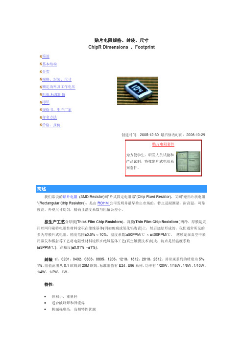
简述 基本结构 分类 规格、封装、尺寸 额定功率及工作电压 阻值,标准阻值 标识 规格书、生产厂家 命名方法 价格、报价
贴片电阻规格、封装、尺寸 ChipR Dimensions 、Footprint
国巨_贴片电容_规格说明UPY-GP_NP0_16V-to-50V_16
P r o d u c t S p e c i f i c a t i o n –M a r c h 7, 2017 V .16DATA SHEETSURFACE-MOUNT CERAMIC MULTILAYER CAPACITORSGeneral purposeClass 1, NP016 V TO 50 V0.22 pF to 100 nFRoHS compliant & Halogen FreeSCOPEThis specification describes NP0 series chip capacitors with lead-free terminations. APPLICATIONS●Consumer electronics for example-Tuners-Television receivers-All types of cameras●Telecommunications●Data processing FEATURES●Supplied in tape on reel●Nickel-barrier end termination ●RoHS compliant●Halogen Free compliant ORDERING INFORMATION - GLOBAL PART NUMBER, PHYCOMP CTC & 12NCAll part numbers are identified by the series, size, tolerance, TC material, packing style, voltage, process code, termination and capacitance value.Y A G E O B R A N D o r d e r i n g c o d eGLOBAL PART NUMBER(PREFERRED)CC XXXX X X NPO X BN XXX(1) (2) (3) (4) (5)(1) SIZE – INCH BASED (METRIC)0201 (0603)0402 (1005)0603 (1608)0805 (2012)1206 (3216)1210 (3225)1812 (4532)(2) TOLERANCEB= ±0.1 pFC= ±0.25 pFD= ±0.5 pFF= ±1%G= ±2%J= ±5%K= ±10%(3) PACKING STYLER= Paper/PE taping reel; Reel 7 inchK= Blister taping reel; Reel 7 inchP= Paper/PE taping reel; Reel 13 inchF= Blister taping reel; Reel 13 inchC= Bulk case(4) RATED VOLTAGE7= 16 V8= 25 V9= 50 V(5) CAPACITANCE VALUE2 significant digits+number of zerosThe 3rd digit signifies the multiplying factor, and letter R is decimal pointExample: 121 = 12 x 101 = 120 pF0.6 ±0.03 0.3 ±0.03 Refer to table 2 to 50.10 0.20 0.20 0402 1.0 ±0.05 0.5 ±0.05 0.20 0.30 0.40 0603 1.6 ±0.10 0.8 ±0.10 0.200.60 0.40 0805 2.0 ±0.10 (1) 1.25 ±0.10 (1) 0.25 0.75 0.70 2.0 ±0.20 (2) 1.25 ±0.20 (2) 1206 3.2 ±0.15 (1) 1.6 ±0.15 (1) 0.25 0.75 1.40 3.2 ±0.30 (2) 1.6 ±0.20 (2) 1210 3.2 ±0.20 2.5 ±0.20 0.25 0.75 1.40 18124.5 ±0.203.2 ±0.200.250.752.20NOTE1. Dimension for size 0805 and 1206, C ≤ 1 nF2. Dimension for size 0805 and 1206, C > 1 nFDIMENSIONO U T L I N E SFig. 2 Surfacemounted multilayer ceramic c apacitor dimension CONSTRUCTION The capacitor consists of a rectangular block of ceramic dielectric in which a number of interleaved metal electrodes are contained. This structure gives rise to a high capacitance per unit volume.The inner electrodesare connected to the two end terminationsand finally covered with a layer of plated tin (NiSn). The terminations are lead-free.A cross section of the structure is shown in Fig.1.Surface mounted multilayer ceramic capacitor constructionC APACITANCE RANGE & THICKNESS FOR NP0CAPACITANCE RANGE & THICKNESS FOR NP0T able 3Sizes from 0201 to 0603 (continued)CAP.020*********25 V50 V16 V25 V50 V16 V25 V50 VNOTE1.Values in shaded cells indicate thickness class in mm2.Capacitance value of non E-12 series is on requestCAPACITANCE RANGE & THICKNESS FOR NP0T able 4Sizes from 0805 to 1812CAP.080512061210181216 V25 V50 V16 V25 V50 V25 V50 V 50 VNOTE1.Values in shaded cells indicate thickness class in mm2.Capacitance value of non E-12 series is on requestCAPACITANCE RANGE & THICKNESS FOR NP0T able 5Sizes from 0805 to 1812 (continued)CAP.080512061210181216 V25 V50 V16 V25 V50 V25 V50 V50 VNOTE1.Values in shaded cells indicate thickness class in mm2.Capacitance value of non E-12 series is on requestTHICKNESS CLASSES AND PACKING QUANTITYELECTRICAL CHARACTERISTICSN P0D I E L E C T R I C C A P A C I T O R S;N I S N T E R M I N A T I O N SUnless otherwise stated all electrical values apply at an ambient temperature of 20±1 °C, an atmospheric pressure of 86 to 106 kPa, and a relative humidity of 63 to 67%.DESCRIPTION VALUE Capacitance range 0.22 pF to 100 nF Capacitance toleranceC < 10 pF ±0.1 pF, ±0.25 pF, ±0.5 pFC ≥ 10 pF±1%, ±2%, ±5%, ±10% Dissipation factor (D.F.)C < 30 pF≤ 1 / ( 400 + 20C )C ≥ 30 pF≤ 0.1 % Insulation resistance after 1 minute at U r (DC) Rins≥ 10 GΩ or R ins × C r≥ 500 seconds whichever is less Maximum capacitance change as a function of temperature(temperature characteristic/coefficient):±30 ppm/°COperating temperature range: –55 °C to +125 °C T able 7Fig. 4 Typical capacitance change with respect tothe capacitance at 1 V as a function of DC voltage Fig. 3 Typical temperature coefficient as a function oftemperatureSample limits (broken lines).Requirement levels (dotted lines)Fig. 5 Typical tan δ as a function of temperature SOLDERING RECOMMENDATIONT able 8SOLDERING METHOD SIZE02010402060308051206≥ 1210Reflow Reflow only≥ 0.1 µF≥ 1.0 µF≥ 2.2 µF≥ 4.7 µF Reflow only Reflow/Wave--- < 0.1 µF< 1.0 µF< 2.2 µF< 4.7 µF---TESTS AND REQUIREMENTST able 9Test procedures and requirementsTEST TEST METHOD PROCEDURE REQUIREMENTSMounting IEC 60384-21/22 4.3The capacitors may be mounted on printed-circuit boardsor ceramic substratesNo visible damageVisualinspectionand dimension check4.4 Any applicable method using × 10 magnification In accordance with specificationCapacitance 4.5.1 Class 1:f = 1 MHz for C ≤ 1 nF, measuring at voltage 1 V rms at 20 °Cf = 1 KHz for C > 1 nF, measuring at voltage 1 V rms at 20 °CWithin specified toleranceDissipation factor (D.F.) 4.5.2 Class 1:f = 1 MHz for C ≤ 1 nF , measuring at voltage 1 V rms at 20 °Cf = 1 KHz for C > 1 nF, measuring at voltage 1 V rms at 20 °CIn accordance with specificationInsulationresistance4.5.3 At U r (DC) for 1 minute In accordance with specificationTemperature coefficient 4.6 Capacitance shall be measured by the steps shown in thefollowing table.The capacitance change should be measured after 5 min at eachspecified temperature stage.Temperature Coefficient shall be calculated from the formula asbelowTemp, Coefficient =610TxC1C1-C2Δ[ppm/℃]C1: Capacitance at step cC2: Capacitance at 125℃∆T: 100℃(=125℃-25℃)(2) Class IICapacitance Change shall be calculated from the formula asbelow∆C =C1C1-C2x 100%C1: Capacitance at step cC2: Capacitance at step b or d<General purpose series>Class1:∆ C/C: ±30ppmClass2:X7R: ∆ C/C: ±15%Y5V: ∆ C/C: 22~-82%<High Capacitance series>Class2:X7R/X5R: ∆ C/C: ±15%Y5V: ∆ C/C: 22~-82%TEST TEST METHOD PROCEDURE REQUIREMENTS4.7 A force applied for 10 seconds to the line joining theterminations and in a plane parallel to the substrate Forcesize ≥ 0603: 5N size = 0402: 2.5N size = 0201: 1NBond strength of plating on end face 4.8 Mounting in accordance with IEC 60384-22 paragraph 4.3 No visible damageConditions: bending 1 mm at a rate of 1 mm/s, radius jig 5mm<General purpose series>∆C/CClass 1:NP0: within ±1% or 0.5 pFwhichever is greaterResistance to soldering heat IEC 60384-21/224.9Precondition: 150 +0/–10 °C for 1 hour, then keep for 24±1 hours at room temperaturePreheating: for size ≤ 1206: 120 °C to 150 °C for 1 minutePreheating: for size >1206: 100 °C to 120 °C for 1 minuteand 170 °C to 200 °C for 1 minuteSolder bath temperature: 260 ±5 °CDipping time: 10 ±0.5 secondsRecovery time: 24 ±2 hoursDissolution of the end face plating shallnot exceed 25% of the length of theedge concerned<General purpose series>∆C/CClass 1:NP0: within ±0.5% or 0.5 pFwhichever is greaterD.F. within initial specified valueR ins within initial specified valueSolderability 4.10Preheated the temperature of 80 °C to 140 °Cand maintained for 30 seconds to 60 seconds.1. Temperature: 235±5°C / Dipping time: 2 ±0.5 s2. Temperature: 245±5°C / Dipping time: 3 ±0.5 s(lead free)Depth of immersion: 10mm The solder should cover over 95% of the critical area of each terminationRapid change of temperature 4.11Preconditioning;150 +0/–10 °C for 1 hour, then keep for24 ±1 hours at room temperature5 cycles with following detail:30 minutes at lower category temperature30 minutes at upper category temperatureRecovery time 24 ±2 hoursNo visual damage<General purpose series>∆C/CClass 1:NP0: within ±1% or 1 pFwhichever is greaterD.F. meet initial specified valueR ins meet initial specified valueTEST TEST METHOD PROCEDURE REQUIREMENTSDamp heat with U r load IEC 60384-21/224.13 1.Preconditioning, class 2 only:150 +0/-10 °C /1 hour, then keep for24 ±1 hour at room temp2.Initial measure:Spec: refer to initial spec C, D, IR3.Damp heat test:500 ±12 hours at 40 ±2 °C;90 to 95% R.H. 1.0 U r applied4.Recovery:Class 1: 6 to 24 hours5.Final measure: C, D, IRP.S. If the capacitance value is less than the minimum valuepermitted, then after the other measurements have beenmade the capacitor shall be preconditioned according to“IEC 60384 4.1” and then the requirement shall be met.No visual damage after recovery<General purpose series>∆C/CClass 1:NP0: within ±2% or 1 pFwhichever is greaterD.F.Class 1:NP0: ≤ 2 x specified valueR insClass 1:NP0: ≥ 2,500 MΩ or R ins x C r≥ 25swhichever is lessEndurance 4.14 1.Preconditioning, class 2 only:150 +0/-10 °C /1 hour, then keep for24 ±1 hour at room temp2.Initial measure:Spec: refer to initial spec C, D, IR3.Endurance test:Temperature: NP0: 125 °CSpecified stress voltage applied for 1,000 hours:Applied 2.0 x U r for general product.4.Recovery time: 24 ±2 hours5.Final measure: C, D, IRP.S. If the capacitance value is less than the minimum valuepermitted, then after the other measurements have beenmade the capacitor shall be preconditioned according to“IEC 60384 4.1” and then the requirement shall be met.No visual damage<General purpose series>∆C/CClass1:NP0: within ±2% or 1 pF whichever is greaterD.F.Class1:NP0: ≤ 2 x specified valueR insClass1:NP0: ≥ 4,000 MΩ or R ins x C r≥ 40s whichever is lessVoltage proof IEC 60384-1 4.6Specified stress voltage applied for 1 minuteU r≤ 100 V: se ries applied 2.5 U r100 V < U r≤ 200 V series applied (1.5 U r + 100)200 V < U r≤ 500 V series applied (1.3 U r + 100)U r > 500 V: 1.3 U rI: 7.5 mANo breakdown or flashoverREVISION HISTORYREVISION DATE CHANGENOTIFICATIONDESCRIPTIONVersion 16 Mar. 7, 2017 - - 0805 L4 spec updatedVersion 15 Nov. 21, 2016 - - Product range updatedVersion 14 Jul. 22, 2016 - - Add 0805/8.2nF and 10nF/ 16V to 50V, T=1.25mm Version 13 May. 16, 2016 - - Product range updatedVersion 12Feb. 16, 2016- - Product range updatedVersion 11Sep. 11, 2014- - Product range updatedVersion 10Feb. 18, 2014- - Product range updatedVersion 9Jun. 17, 2013- - Product range updatedVersion 8Aug 05, 2011- - Dimension updatedVersion 7Jun 14, 2011- - Size1210 T=1.0mm SPQ added - Dimension updatedVersion 6Jan 06, 2011- - Dimension updatedVersion 5Dec 29, 2010- - Dimension updatedVersion 4Nov 23, 2010- - Dimension updatedVersion 3Apr 20, 2010- - The statement of "Halogen Free" on the cover added- Dimension updatedVersion 2Oct 26, 2009- - Typo updatedVersion 1Jun 02, 2009- - 12NC code updatedVersion 0Apr 15, 2009- - New datasheet for general purpose NP0 series with RoHS compliant- Replace the "16V to 50V" part of pdf files: NP0_16V_7, NP0_16V-to-100V_6, NP0_25V_7, NP0_50-to-500V_11- Combine 0201 from pdf files: UP-NP0X5RX7RY5V_0201_6.3-to-50V_2and UY-NPOX5RX7RY5V_0201_6.3-to-50V_2- Define global part number- Description of "Halogen Free compliant" added。
国巨贴片电容X7R规格书——日科

100 pF 150 pF 220 pF 330 pF 470 pF 680 pF 1.0 nF 1.5 nF 2.2 nF 3.3 nF 4.7 nF 6.8 nF 10 nF 15 nF 22 nF 33 nF 47 nF 68 nF 100 nF 150 nF 220 nF 330 nF 470 nF 680 nF 1.0 µF 2.2 µF 4.7 µF 10 µF 22 µF 47 µF
May. 26, 2015 V.12
Product specification
4
19
Surface-Mount Ceramic Multilayer Capacitors
General Purpose & High Cap.
X7R
6.3 V to 50 V
CAPACITANCE RANGE & THICKNESS FOR X7R
terminations
electrodes
MLB457
ceramic material
Fig. 1 Surface mounted multilayer ceramic capacitor construction
DIMENSION
Table 1 For outlines see fig. 2 TYPE 0201 0402 0603 0805 1206 1210 1812
0.85±0.1
1.25±0.2 0.8±0.15 1.25±0.2 1.25±0.2 1.25±0.2 1.25±0.2
1. Values in shaded cells indicate thickness class in mm 2. Capacitance value of non E-6 series is on request 3. For product with 5% tolerance, please contact local sales force before ordering
国巨阻规格书

OUTLINES
YNSC088
Fig. 8 Chip resistor outlines
marking layer
overcoat
protective glass
resistive layer (Jumper chip is a conductor) inner electrode termination(Ni/matte tin) inner electrode
3.10 ±0.10
AC1218
3.10 ±0.10
AC2010
5.00 ±0.10
AC2512
6.35 ±0.10
For dimension, please refer to Table 1
APPLICATIONS All general purpose applications
Car electronics, industrial application
FEATURES Comply with AEC-Q200 standard
Superior resistance against sulfur containing atmosphere
(3) PACKAGING TYPE R = Paper/PE taping reel
K = Embossed taping reel
(4) TEMPERATURE COEFFICIENT OF RESISTANCE
– = Base on spec
(5) TAPING REEL
07 = 7 inch dia. Reel 13 = 13 inch dia. Reel
Reduce environmentally hazardous waste
国巨_贴片电容_规格说明-ST_NPOX7R_16V-to-3KV_4
DIMENSION Table 1 For outlines see fig. 3
TYPE L1 (mm) W (mm) T (mm)
0402 0603 0805 1206
1210
1808 1812
1.0 ± 0.15 1.6 ± 0.20 1.6 ± 0.25
0.5 ± 0.15 0.8 ± 0.15 0.8 ± 0.25
force before order.
Surface-Mount Ceramic Multilayer Capacitors
Soft Termination
NPO & X7R
Product specification 3
16V to 3KV
19
CONSTRUCTION
The capacitor consists of a rectangular block of ceramic dielectric in which a number of interleaved metal electrodes are contained. This structure gives rise to a high capacitance per unit volume. The inner electrodes are connected to the two end flexible terminations and finally covered with a layer of plated tin (NiSn). The terminations are lead-free. A cross section of the structure is shown in Fig.1 and Fig.2.
贴片电容型对照表三星国巨风华选型替代必备
风华高科电容多层片式陶瓷电容0805 CG 104 J 500 N T1 2 3 4 5 6 71、尺寸2、介质种类3、标称电容量(PF)4、误差级别5、工作电压6、端头类别7、包装方式型号英寸毫米代码介质材料表示方法实际值代码误差表示方法实际电压标记端头材料标记包装0402 0.04*0.02 1.00*0.5 CG COG和NPO 100 10*100J ±5% 6R3 6.3V S 纯银T 编带0603 0.06*0.03 1.6*0.8 101 10*101G ±2% 100 10V C 纯铜 B 散装0805 0.08*0.05 2.00*1.25 102 10*102 C ±0.25PF 250 25V N 三层电镀1206 0.12*0.06 3.2*1.6 500 50V三星电容多层片式陶瓷电容CL 10 C 101 J B 8 N N N C1 2 3 4 5 6 7 8 9 10 11CL表示:多层陶瓷贴片电容2、尺寸3介质种类4、标称电容量(PF)5、误差级别6、工作电压7、厚度8端头类别型号英寸毫米代码介质材料表示方法实际值代码误差表示方法实际电压标记尺寸(mm)标记端头材料0402 0.04*0.02 1.00*0.5 CPRSTUL COGP2HR2HS2HT2HU2JS2L100 10*100 J ±5% R 4V 3 0.3 N 三层电镀0603 0.06*0.03 1.6*0.8 101 10*101 G ±2% Q 6.3V 4 0.50805 0.08*0.05 2.00*1.25 102 10*102 C ±0.25PF P 10V 89ACD0.8 0.9 0.650.851.001206 0.12*0.06 3.2*1.6 OALB 16V 25V 35V 50VAB Y F X X5RX7RX7SY5VX6SKMZ±10%±20%+80/-20%CDEFGHIJK100V200V250V350V500V630V1000V2000V3000V国巨(YAGEO)电容多层片式陶瓷电容CC ×××× × ×NPO ×BN ×××1 2 3 4 51、尺寸2、误差精度3、包装形式4、实际电压值5、标称电容量型号英制型号公制代码误差表示方法实际值代码电压代码实际值0201 0603 BCDFGJ±0.1PF±0.25PF±0.5PF±1%±2%±5%R 纸卷盘7inch 7 16V 100 10*1000402 1005 K 吸塑卷盘7inch 8 25V 101 10*101 0603 1608 P 纸卷盘13inch 9 50V 102 10*102 0805 2012 F 吸塑卷盘13inch1206 3216 C 散装1210 32251812 4532TDK贴片电容型号TDK贴片电容的参数识别C 2012 X7R 1H 104 K T系列名称体积材料电压容量误差包装0603=0201 CH 0J=6.3V C=0.25 T=卷带1005=0402 COG 1A=10V D=0.5 B=袋装1608=0603 JB 1C=16V J=5%2012=0805 JF 1E=25V K=10%3216=1206 X7R 1H=50V M=20%3225=1210 X5R 2A=100V Z=+80-20%4532=1812 Y5V 2E=250V5650=2220 2J=630V4520=1808 3A=1KV3D=2KV3F=3KV。
国巨电容规格书
Conditions
NPO
Requirements
X7R
Y5V
Bending rate 1mm/s, jig. Radius ∆C/C ≤ 1%
∆C/C ≤ 10%
∆C/C ≤ 20%
340mm
260±5°C for 10±0.5s in static ∆C/C ≤ 0.5% or 0.5pF, -5% ≤ ∆C/C ≤ 10% -10% ≤ ∆C/C ≤ 20%
Code 9~11 Material
NPO X7R Z5U Y5V
Code 15~17
Capacitance Value
(2 significant digits + No.
of Zeros)
The 3rd digit:
0=×1
3 = × 103
1 = × 10 4 = × 104
2 = × 102 5 = × 105
CC1812 4.5±0.20 3.2±0.20 0.50 1.80 0.25 0.75 2.20
CC2220 5.7±0.20 5.0±0.20 0.50 1.80 0.25 0.75 2.20
Unit: mm
-3-
YAGEO CORPORATION
Aging Rate
∆C/C (%) 10
Aging Curve
国巨电容国巨贴片电容国巨电阻规格书国巨电阻规格书中文国巨电容型号国巨电子电容厂国巨电子
YAGEO CORPORATION
1. SUBJECT: This specification applies on the chip capacitor made by Yageo Corporation.
国巨 电容 MSDS
SAFETY DATA SHEETNo.R-100810-001Date : February 10,2013SECTION 1. - - - - - - - - - CHEMICAL IDENTIFICATION- - - - - - - - - Product name: MLCC (Multi-Layer Ceramic Capacitor) Product code: NPO,X7R,X5R,Y5V SERIES Manufacturer’s name : Yageo Corporation Nantze BranchAddress : No.16, West 3rd St, N.E.P.Z., Kaohsiung 81170, Taiwan,R.O.C. TEL: 886-7-3614101 FAX :886-7-9616898SECTION 2. - - - - - COMPOSITION/INFORMATION ON INGREDIENTS - - - - - NPO(NME) SERIES Material Ceramic Inner electrode Termination Termination plating NPO SERIES Material Ceramic Inner electrode Termination Termination plating BaTiO3 Nickle Copper Nickle Tin X7R / X5R SERIES Material Ceramic Inner electrode Termination Termination plating BaTiO3 Nickle Copper Nickle Tin wt% 46.2-94 1.6-12.8 2.95-24.5 0.075-5 0.26-17.95 CAS No 12047-27-7 7440-02-0 7440-50-8 7440-02-0 7440-31-5 wt% 67-87 3.2-8.4 4.3-19.3 0.4-1.9 1.2-5.6 CAS No 12047-27-7 7440-02-0 7440-50-8 7440-02-0 7440-31-5 TiO2 Silver Palladium Silver Nickle Tin wt% 88-92.5 3.9-7.1 0.4-0.8 2.2-2.9 0.2-0.3 0.65-0.8 CAS No 13463-67-7 7440-22-4 7440-05-3 7440-22-4 7440-02-0 7440-31-5Y5V SERIES Material Ceramic Inner electrode Termination Termination plating BaTiO3 Nickle Copper Nickle Tin wt% 73.2-85 7.3-12.4 4.1-17.4 0.11-0.5 0.4-1.65 CAS No 12047-27-7 7440-02-0 7440-50-8 7440-02-0 7440-31-5SECTION 3. - - - - - - - - - - HAZARDS IDENTIFICATION - - - - - - - - Hazardous product for human health if swallowed SECTION 4. - - - - - - - - - - FIRST-AID MEASURES- - - - - - - - - - Main effect : Risk of stomachache Eye contact : No irritation in human. Skin contact : No irritation in human.Ingestion : If swallowed, wash out mouth with water provided person is conscious. First aid : Consult with a physician in all cases.and take to hospital. SECTION 5. - - - - - - - - - FIRE FIGHTING MEASURES - - - - - - - - - Common extinguishing means : In case of fire in close proximity,all means of extinguishing are acceptable,e.g. foam,dry chemical, carbon dioxide,water. Inappropriate extinguishing means : No restrictionSpecific hazards : Non-combustible if temperature is lower than 1200 degree C. Protective measure in case of intervention : The product does not require any apecialprecaution Extinguishing instruction : Keep person removing from an upwind of fire. SECTION 6. - - - - - - - - ACCIDENTAL RELEASE MEASURES- - - - - - - - Sweep up, place in a bag and collect for waste disposal. Prevent discharge into the environment(sewers,river,soil,- - - )SECTION 7. - - - - - - - - - - HANDLING AND STORAGE- - - - - - - - - - Handling : Keep in a above environment , and original packing ,closed to be free of chlorine and bromide material contaminant . Storage : Keep storage place temperature from 20 to 40 degree C,humidity from 45 to 75% RH . SECTION 8. - - - - - - EXPOSURE CONTROLS/PERSONAL PROTECTION- - - Engineering control : Premises ventilation Authorized limit values : Not applicable Respiratory protection : Not applicable Hand protection : Not applicable Eye protection : Not applicable Skin protection : Not applicable Other precaution : Not applicableSECTION 9. - - - - - - - PHYSICAL AND CHEMICAL PROPERTIES - - - - - - Physical state : Solid Appearance : Gray brown / Silver metal Order : None PH value : Not applicable Decomposition temperature : Not applicable Flash point : Not applicableBoiling point : Not applicable Melting point : About 1200 degree C Flammable limits(LEL) : Not applicable Flammable limits(UEL) : Not applicableSECTION 10. - - - - - - - - -STABILITY AND REACTIVITY - - - - - - - - Stability : Stable on normal temperature and pressure Condition to avoid : High temperature and humidity Hazardous reaction with : Not applicable Hazardous decomposition Products : Not applicable SECTION 11. - - - - - - - - - TOXICOLOGICAL INFORMATION - - - - - - - Acute effects : Not applicable Toxicity : Not traceableSECTION 12. - - - - - - - - - ECOLOGICAL INFORMATION - - - - - - - - - Biological oxygen demand : Not applicable Chemical oxygen demand : Not applicableBiological /Chemical oxygen demand ratio : Not applicable Biochemical factor : Not applicable Ecotoxicity : Not applicable SECTION 13. - - - - - - - - - DISPOSAL CONSIDERATIONS - - - - - - - - Installated or dump in a incinerator equipped in accordance with all federal, state , local and national environmental regulations. SECTION 14. - - - - - - - - - - TRANSPORT INFORMATION - - - - - - - - No classification assigned. Not subject to Transport-regulation Dangerous Substances under IATA Dangerous Goods Regulations. SECTION 15. - - - - - - - - - REGULATORY INFORMATION - - - - - - - - - Designation according to Sony SS-00259 ,EU WEEE/ROHS and customer ’s related standard. No classification assigned. SECTION 16. - - - - - - - - - - OTHER INFORMATION- - - - - - - - - - - These data are based on our present knowledge.However,they shall not constitute a guarantee for any specific product feature and shall not establish a legally valid contractual relationship.。
国巨-100 pF to 100 μF X5R规格书
ORDERING INFORMATION - GLOBAL PART NUMBER, PHYCOMP CTC & 12NC All part numbers are identified by the series, size, tolerance, TC material, packing style, voltage, process code, termination and capacitance value. YAGEO BRAND ordering code GLOBAL PART NUMBER (PREFERRED )
Fig. 1 Surface mount multilayer ceramic capacitor construction
OUTLINES T (MM) L2 / L3 (mm) min.
0.10
W (mm)
0.3 ± 0.03 (1) 0.3 ± 0.05 (2) 0.5 ± 0.05 (1) 0.5 ± 0.15 (2) 0.5 ± 0.20 (3) 0.8 ± 0.10 (1) 0.8 ± 0.15 (2) 0.8 ± 0.20
(3)
L4 (mm) min.
0.20
For dimension see Table 1
max.
0.20
0402
0.20
0.30
0.40
1.0 ± 0.20 (3) 1.6 ± 0.10 (1)
0603
1.6 ± 0.15 (2) 1.6 ± 0.20
(3)
0.20 Refer to table 2 to 4
GLOBAL PART NUMBER (preferred), PHYCOMP CTC (for North America) and 12NC (traditional) codes are acceptable to order Phycomp brand products. GLOBAL PART NUMBER (PREFERRED ) For detailed information of GLOBAL PART NUMBER and ordering example, please refer to page 2. 12NC
- 1、下载文档前请自行甄别文档内容的完整性,平台不提供额外的编辑、内容补充、找答案等附加服务。
- 2、"仅部分预览"的文档,不可在线预览部分如存在完整性等问题,可反馈申请退款(可完整预览的文档不适用该条件!)。
- 3、如文档侵犯您的权益,请联系客服反馈,我们会尽快为您处理(人工客服工作时间:9:00-18:30)。
CC 0805 K K X7R 9 B N 104
Code 1~2 Series Name CC = Multi-layer
chip cap. CA = Cap. Array CL=Low. Inductance
Code 3~6
Size Code
inches (mm)
0402 (1005)
Code 9~11 Material
NPO X7R Z5U Y5V
Code 15~17
Capacitance Value
(2 significant digits + No.
of Zeros)
The 3rd digit:
0=×1
3 = × 103
1 = × 10 4 = × 104
2 = × 102 5 = × 105
1-2℃/Sec ramp 溫昇 Preheat 150-183℃:2-3 minutes Time above 183℃:60-100 seconds Peak Temperature:230±10℃
Module should only be in oven for 5.5-6 minute
-5-
IR: 4000MΩ or
Whichever is less
RxC ≥ 50s
Precondition for Class 2 Ur ≤
RxC ≥ 40s
Whichever is less
16Vwhichever s lessPCB Layout for Reliability test:
Solder resist
CC1812 4.5±0.20 3.2±0.20 0.50 1.80 0.25 0.75 2.20
CC2220 5.7±0.20 5.0±0.20 0.50 1.80 0.25 0.75 2.20
Unit: mm
-3-
YAGEO CORPORATION
Aging Rate
∆C/C (%) 10
Aging Curve
1000hours
Tan δ: ≤ 2xspecified
Tan δ: ≤ 7%, 12.5%, 15%
Class 2 only 1000 hours, At
Value
IR: 2000MΩ or
upper category temperature, No
RxC ≥ 50s
IR: 2000MΩ or
voltage (for Ur ≥ 1KV)
X7R/Y5V: 1Vrms/1KHz
Z5U: 0.5Vrms/1KHz
NPO 16V, 0±60ppm/K NPO >16V, 0±30ppm/K
C < 5pF; ±0.25pF C ≥ 5pF; ±0.5pF C ≥10pF; ±5%, ±10% C < 10pF: Tan δ≤10(3/C+0.7)x10-4 or 30 x10-4 whichever is less.
1minute
At 2.5Ur (for Ur ≤ 100V)
No breakdown
1.5Ur + 100V (for Ur > 100V)
1.5Ur,Ur=1000V
1.2Ur,Ur>1000V for 5Second
Rins > 10GΩ or RinsxC≥500s, Whichever is less.
Solder land
-6-
0402 0603 0402 0603 0805 1206 1210 0402 0603 0805 1206 1210 1812 0603 0805 1206 1210 1812 0805 1206 1210 1812 1206 1210 1812 1206 1812 1206 1808 1812 1808 1812
Rins > 10GΩ or RinsxC≥100s, whichever is less.
-2-
YAGEO CORPORATION
4. DIMENSION (mm)
T L1
W
L3
L2
L
Style
L
W
T
L1;L2
L3
MIN. MAX. MIN. MAX. Min.
CC0402 1.0±0.05 0.5±0.05 0.45 0.55 0.15 0.30 0.40
At upper category temperature, ∆C/C:2% or 1pF
∆C/C: ≤ 20%
2xUr applied (1.5Ur for
whichever is greater
-40% ≤ ∆C/C ≤ 30%
Ur>50V,1.2Ur for Ur ≥ 1KV) for
Tan δ: ≤ 7%
6 = × 106
Letter R is decimal point
Code 14 Series N = Non BME B = BME
Code 13 Termination B = Ni-barrier
A = PdAg
Code 12 Rated voltage 5 = 6.3V 6 = 10V 7 = 16V 8 = 25V 9 = 50V 0 = 100V A= 200V B = 500V C= 1000V D= 2000V E= 3000V Y= 250V Z= 63V
0603 (1608)
0805 (2012)
1206 (3216)
1210 (3225)
1808 (4520)
1812 (4532)
2220
(5750)
Code 7
Capacitance tolerance
A = ±0.05pF G = ±2%
B = ±0.1pF
J = ±5%
C = ±0.25pF K = ±10%
-40% ≤ ∆C/C ≤ 30%
(500 hours for Y5V)
Tan δ: ≤ 7%
Class 2 only 56 days at 40°C, Tan δ: ≤ 2xspecified
Tanδ: ≤ 7%, 12.5%, 15%
90 to 95% RH, No voltage(for
Value
D = ±0.5pF
M = ±20%
F = ±1%
Z= -20%+80%
Code 8 Packing style R = Paper tape reel ϕ 7 inch P = Paper tape reel ϕ 13 inch K = Embossed plastic tape reel ϕ 7 inch. F = Embossed plastic tape reel ϕ 13 inch. B = Bulk Bag C = Bulk Cassette
0
-10
-20
-30 1
10
100
NPO X7R Y5V
1000 Hours
-4-
YAGEO CORPORATION
Reflow Profile
Temp
℃
245 225
183
150
235±10
120-180 Sec.
60-100 Sec.
Time (seconds)
Profile Parameters 參數
Endurance
Conditions
NPO
Requirements
X7R
Y5V
Bending rate 1mm/s, jig. Radius ∆C/C ≤ 1%
∆C/C ≤ 10%
∆C/C ≤ 20%
340mm
260±5°C for 10±0.5s in static ∆C/C ≤ 0.5% or 0.5pF, -5% ≤ ∆C/C ≤ 10% -10% ≤ ∆C/C ≤ 20%
solder bath
whichever is greater
235±5°C for 2±0.5 s in a static 75% minimum coverage of metallic area solder bath
NPO/X7R:-55°C to +125°C, ∆C/C ≤ 1% or 1pF, ∆C/C: ≤ 15%
YAGEO CORPORATION
5. TESTS AND REQUIREMENTS
IEC 384-10 4.9 4.10 4.11 4.12 4.14
4.15
Test items Bending Resistance to soldering heat Solderability Rapid change of temperature Damp heat, steady state
∆C/C: ≤ 20%
5 cycles
whichever is greater
Y5V: -25°C to +85°C, 5 cycles
At 40°C, 90 to 95% RH and Ur ∆C/C:2% or 1pF
∆C/C: ≤ 15%
applied (max. 500V, for 56 days whichever is greater
CC0603 1.6±0.10 0.8±0.10 0.70 0.90 0.20 0.60 0.40
CC0805 2.0±0.10 1.25±0.10 0.50 1.35 0.25 0.75 0.55
CC1206 3.2±0.15 1.6±0.15 0.50 1.35 0.25 0.75 1.40
CC1210 3.2±0.20 2.5±0.20 0.50 1.80 0.25 0.75 1.40