
Profibus通信使用说明书
应答 ID
功能
0 0 无要求
1,2 1 回答参数值(Word)
2 2 回答参数值(Long Word)
3 3 拒绝要求(应答出错号)
8 根据PKW接口,没有权利变更参数
注意事项: ・数据方向、以PLC侧为主体进行收发信。 ・收信PZD的分配,通过PNU=915、IND1~10进行。(PKE2数据为PNU=800时的IND。) ・送信PZD的分配,通过PNU=916、IND1~10进行。(PKE2数据为PNU=800时的IND。)
916来改变PZD领域里的分配,即发信时将需要读取数据的IND号码写入PWE2, 收信时通过PZD领域内对应的字来读取想要知道的数据。
2010-11-12 李 锋
Private!
私人制作,仅供参考!
N/A
5/19
2.传送指令(2/2)
PNU IND
项目
915 1 PSB送信数据分配1
915 …
…・
PLC→DDC送信数据
No 领域
内容
数据范围
单位及幅值
1
PKE
2 3
PKW
IND(变频器只识别高8位) PWE1
参照传送指令(P5,6)
4
PWE2
1
STW1(控制字Word1)
(参照P7)
2
频率指令 F*
-32768~32767
16384/100%
3
不使用
4
STW2(控制字Word2)
(参照P8)
5 PZD 6
(参照P9)
-32768~32767
16384/100%
(PWE1:Long Word 上位侧、PWE2:Word 或者 Long Word 下位侧)
备注
通过PNU=915 IND1,2分配定义
备注
通过PNU=916 IND1,2分配定义
PKE 15 14 13 12 11 10 9 8 7 6 5 4 3 2 1 0
3 4
PZD
不使用 STW2(控制字Word2)
(参照P8)
5
不使用
6
不使用
(PWE1:Long Word 上位侧、PWE2:Word 或者 Long Word 下位侧)
DDC→PLC收信数据
No 领域
内容
数据范围
单位及幅值
1
PKE
2
IND(变频器只识别高8位)
3 PKW
PWE1
参照传送指令(P5,6)
注意事项:
・数据方向、以PLC侧为主体进行收发信。 ・变频器只能识别IND的高8位,所以需要将需要的IND号码写入发信IND字的高8位
比如,需要将IND设为5,则发送的IND字应设为0500H ・因为变频器只能识别8位IND数值,所以大于255的IND无法被传输,即通过PNU=
800,无法读取变频器内部数据(IND为301到399) ・需要读取IND大于255的数据(变频器内部数据),必须先通过PKW领域使用PNU=
4
PWE2
1
ZSW1(状态字Word1)
(参照P9)
2
频率指令 F*
-32768~32767
16384/100%
3 4
PZD
电流检出 Idet ZSW2(状态字Word2)
-32768~32767
8000/100%
(参照P10)
5
不使用
6
不使用
(PWE1:Long Word 上位侧、PWE2:Word 或者 Long Word 下位侧)
PNU:参数No.(0~1999)
备注
通过PNU=915 IND1~10分配定义
备注
通过PNU=916 IND1~10分配定义
FRENIC4600FM5 Profibus 通讯说明书
AK(要求)
ID
功能
0 无要求
1 要求参数值
2 变更参数值(Word)
3 变更参数值(Long Word)
AK(应答)
DDC→PLC收信数据
No 领域
内容
1
ZSW1(状态字Word11)
2
频率指令 F*
3 4
PZD
电流检出 Idet ZSW2(状态字Word2)
5
不使用
6
不使用
数据范围 (参照P7)
-32768~32767
单位及幅值 16384/100%
(参照P8)
数据范围 (参照P9)
-32768~32767 -32768~32767
不使用 加速率 T_AC
0~65535
100/SEC
7
减速率 T_DC
0~65535
100/SEC
8
不使用
9
不使用
10
不使用
(PWE1:Long Word 上位侧、PWE2:Word 或者 Long Word 下位侧)
DDC→PLC收信数据
No 领域
内容
数据范围
单位及幅值
1
PKE
2 3
PKW
IND(变频器只识别高8位) PWE1
915 10 PSB送信数据分配10
916 1 PSB收信数据分配1
916 …
…・
916 10 PSB收信数据分配10
918 - 节点地址
922 - 传文选择 923 1~255 内部参数号码分配
944 - 故障计数器
16384/100%
(PWE1:Long Word 上位侧、PWE2:Word 或者 Long Word 下位侧)
Z
DDC→PLC收信数据
No 领域
内容
数据范围
数据单元量
1
PKE
2
IND(变频器只识别高8位)
3 PKW
PWE1
传送指令参照(P5,6)
4
PWE2
1 2
PZD
ZSW1(状态字Word) 频率指令 F*
AK
SPM
PNU(Parameter number)
AK:要求/应答ID(0~15)
SPM:自发信息用跳动位(未使用)
PNU:参数No.(0~1999)
AK(要求)
ID
功能
0 无要求
1 要求参数值
2 参数值变更(Word)
3 参数值变更(Long Word)
注意事项:
AK(应答)
应答 ID
功能
0 0 无要求
单位及幅值 16384/100%
数据范围 (参照P9)
-32768~32767
单位及幅值 16384/100%
PPO型4:无PKW领域、PZD领域6Word
PLC→DDC送信数据
No 領域
内容
1
STW1(控制字Word1)
2
频率指令 F*
3 PZD 4
不使用 STW2(控制字Word2)
5
不使用
6
不使用
R
○
参照内部数据一览表
(P14~17)
R
○
*上面红底处,因IND数值限制(不能超过255),实际无法执行,详见下面的说明。
为PROFI-drive规格
单位及幅值
16384/100% 8000/100% 100/SEC 100/SEC
1000/100% 1000/100%
1/SEC
FRENIC4600FM5 Profibus 通讯说明书
ZSW1
R
STW2 R/W
ZSW2
R
NSOLL_A R/W
数据范围
参照控制字Word1(P7) 参照状态字Word1(P9) 参照控制字Word2(P8) 参照状态字Word2(P10)
-32768~32768
F4600 VM5
○ ○ ○ ○ ○
800 51 输出电流
IDET
R
-32768~32768
参照传送指令(P5,6)
4
PWE2
1
ZSW1(状态字Word1)
(参照P9)
2
频率指令 F*
-32768~32767
16384/100%
3
电流检出 Idet
-32768~32767
8000/100%
4
ZSW2(状态字Word2)
(参照P10)
5 6Biblioteka PZD不使用 不使用
7
不使用
8
不使用
9
故障(1)
故障(1)参照(P12)
(参照P10)
单位及幅值
16384/100% 16384/100%
FRENIC4600FM5 Profibus 通讯说明书
注意事项: ・数据方向、以PLC侧为主体进行收发信。
2010-11-12 李 锋 私人制作,仅供参考!
Private!
N/A
3/19
PPO型5:PKW领域4Word、PZD领域10Word
N/A
1/19
PPO型2:PKW领域4Word、PZD领域6Word
PLC→DDC送信数据
No 领域
内容
数据范围
单位及幅值
1
PKE
2
IND(变频器只识别高8位)
3 PKW
PWE1
参照传送指令(P5,6)
4
PWE2
1
STW1(控制字Word1)
(参照P7)
2
频率指令 F*
-32768~32767
16384/100%
需要改变收发信PZD领域内各字的定义时,可以在PKW内通过PNU=915或916来进行,IND值为对应的PZD领域内 字的顺序号,PKE2则为PNU=800时的IND号码,具体的例子见P19
PROFIBUS-DP主站接口卡用户使用说明书
FW239-DP 应用介绍报告人报告人::张晓刚2概述功能使用SP/XP/FW239-DP + Pro V2.5 + SP002DP 可以将标准的PROFIBUS-DP 从站设备连入Jx300X 、Jx300XP 、ECS-100、ECS-100X 系统,通过DP/PA 耦合器、DP/PA 链接器还可以将PA 设备连入系统。
一块FW239-DP 可同时连接DP 和PA 设备 适用范围连接标准PROFIBUS 从站设备不适用范围主主通信,将DP 主站设备连入系统,如某些不支持从站功能的S7-400 CPU非标准PROFIBUS 设备3FW239-DP4TB239-DP5SP/XP239-DP系统结构系统通讯原理8系统配置规范主站接口卡必须与AdvanTrol-Pro(V2.50)软件包配合使用。
在JX-300X 、JX-300XP 、ECS-100系统中,主站接口卡和控制站的数量和不大于15个。
在ECS-100X 系统中,主站接口卡和控制站的数量和不大于31个,其中FW239-DP 的数量不大于15个。
每块主站接口卡可以带最多31个DP 从站。
每块主站接口卡最大可以有3.5k Byte 的输入数据和3.5k Byte 的输出数据。
每块主站接口卡的实时数据位号数不大于4096个。
每块主站接口卡参与控制的输入数据不大于512Byte ,参与控制的输出数据不大于512Byte(和主控卡站间交换数据长度)。
每块主站接口卡只能由一个控制器控制其输出,一个控制器也只能控制一块主站接口卡的输出。
9DP 配置在JX-300X 、JX-300XP 系统中,需要配置SP/XP239-DP 标准35mm 导轨。
在ECS-100/X 系统中,需要配置FW239-DP 、TB239-DP 总线连接器。
总线电缆。
上位机软件。
Advantrol (V2.5)+SP002 DP。
10PA 配置链接器:6ES7 157-0AA82-0XA0耦合器:6ES7 157-0AC81-0XA0普通24V 电源PA 电缆 T 型头:6GK1 905-0AA00(每个仪表需要一个)(或分线盒,根据具体情况而定)终端电阻:6GK1 905-0AE00(一包5个,每条PA 线需要一个)标准导轨:6ES7390-1AB60-0AA0(160mm )或6ES7390-1AE80-0AA0(482mm )11PA 配置规则一个DP 系统的所有DP 从站(包括IM157)个数之和最大为31每个DP 从站(IM157)下面最多可以连接61个PA 从站,槽位的总数最大为(236-PA 从站个数) 每个IM157最多可以连接5个DP/PA 耦合器每个DP/PA 耦合器下面可连接的PA 从站的个数由DP/PA 耦合器的供电电流以及PA 设备的耗电情况决定 增加耦合器可以增加PA 系统的供电电流每个IM157最大的组态数据、参数数据、诊断数据、以及I/O 数据最大均为240字节在上层的DP 系统,链接器作为一个DP 从站并作为一个网关连接下层的总线系统(PA 现场设备)12安装方式FW239-DP 卡安装在ECS-100机笼内任意I/O 槽位上(不能插在主控制卡或数据转发卡槽位),占用两个I/O 槽位的宽度;端子板TB239-DP 直接插在机笼背面和FW239-DP 对应I/O 槽位的DB25接口上。
西门子S7-1200-PROFIBUS-CM-1242-5操作说明

1.4
运行要求............................................................................................................................... 8
1.5
PROFIBUS 组态示例............................................................................................................ 9
合格的专业人员
本文件所属的产品/系统只允许由符合各项工作要求的合格人员进行操作。其操作必须遵照各自附带的文件说明,特 别是其中的安全及警告提示。 由于具备相关培训及经验,合格人员可以察觉本产品/系统的风险,并避免可能的危 险。
Siemens 产品
请注意下列说明:
商标 责任免除
警告 Siemens 产品只允许用于目录和相关技术文件中规定的使用情况。如果要使用其他公司的产品和组件,必须得到 Siemens 推荐和允许。正确的运输、储存、组装、装配、安装、调试、操作和维护是产品安全、正常运行的前 提。必须保证允许的环境条件。必须注意相关文件中的提示。
5.2 5.2.1 5.2.2 5.2.3 5.2.4 5.2.5
诊断 .................................................................................................................................... 25 诊断方法............................................................................................................................. 25 DP 从站诊断....................................................................................................................... 26 标准诊断............................................................................................................................. 28 DP-V1 中的设备特定诊断 ................................................................................................... 30 DP-V0 中的设备特定诊断 ................................................................................................... 34
AELTA DVPPF02-H2 PROFIBUS DP 从站通讯模块 说明书

DVPPF02-H2
PROFIBUS DP 从站通讯模块 操作手册
DVP-0205310-01
PROFIBUS DP 从站通讯模块 DVPPF02-H2
注意事项
3 此操作手册提供功能规格、安装、基本操作与设定,以及有关于网络协议内容的介绍。 3 本机为开放型 (OPEN TYPE) 机壳,因此使用者使用本机时,必须将其安装于具防尘、防潮及免于电击/
5 GSD 文件介绍 .....................................................................................................................................9 6 LED 指示灯说明与故障排除................................................................................................................9 7 应用范例(一).................................................................................................................................10
PROFIBUS-DP用户手册(V1.01)

文档编号 版本 密级 PRONET-S002 V1.01内部公开 南京埃斯顿自动控制技术有限公司研发部资源类别:共25页PROFIBUS-DP 用户手册拟制: 日期: 审核: 日期: 批准: 日期:修订记录日期 修订版本 描述 作者 2008/08/28 1.00 初稿完成 徐慧2009/09/14 1.01 Profibus-DPV0, DPV1 , DPV2合并在DP100模块的一个DSP程序。
易健第一章:前言本说明书内容主要介绍PROFIBUS接线,配置,功能和软件协议。
z第二章:PROFIBUS简介z第三章:产品概述z第四章:安装信息z第五章:PROFIBUS-DP通讯z第六章:GSD文件说明及参数设定z第七章:LED灯指示说明及故障排除方法z第八章:参数模式/对象字典z第九章:参数描述第二章:PROFIBUS 简介2.1 PROFIBUS 概况PROFIBUS是一个国际化、开放性且独立于供货商的(vendor-independent)通讯协议标准,广泛应用于生产、制造、加工和建筑自动化以及其它自动化控制领域。
PROFIBUS 根据不同需求及应用,有三种主要类型:PROFIBUS-DP、PROFIBUS-PA及PROFIBUS-FMS:z PROFIBUS-DP(Decentralized Periphery):PROFIBUS-DP是一种速率快且成本低的通讯系统,专为高速数据传输而设计的。
PROFIBUS-DP被广泛使用,尤其在远程I/O系统、马达控制中心以及变频器的应用上。
采用PROFIBUS-DP连接自动化系统与分散外围装置间通讯时,可达到最佳化的效果。
z PROFIBUS-PA(Process Automation):PROFIBUS-PA(通常附有 MBP-IS 传输技术)是一种用于过程自动化的PROFIBUS通讯系统,PROFIBUS-PA以PROFIBUS-DP为基础,在数据传输上为PROFIBUS-DP通讯协议的延伸,专门支持本质安全防爆应用,可藉由本质安全防爆MBP-IS接口,应用在有爆炸危险的区域。
利用PROFIBUS协议进行网络通信
利用PROFIBUS协议进行网络通信PROFIBUS是世界上第一个开放式现场总线标准,目前技术已成熟,其应用领域掩盖了从机械加工、过程掌握、电力、交通到楼宇自动化的各个领域。
PROFIBUS于1995年成为欧洲工业标准(EN50170),1999年成为国际标准(1EC61158-3)。
在S7-200 系列plc的CPU中,CPU22X都可以通过增加EM277 PROFIBUS-DP 扩展模块的方法支持PROFIBUS DP 网络协议。
最高传输速率可达12Mbit/s。
采纳PROFIBUS的系统,对于不同厂家所生产的设备不需要对接口进行特殊的处理和转换,就可以通信。
PROFIBUS 连接的系统由主站和从站组成,主站能够掌握总线,当主站获得总线掌握权后,可以主动发送信息。
从站通常为传感器、执行器、驱动器和变送器。
它们可以接收信号并赐予响应,但没有掌握总线的权力。
当主站发出恳求时,从站回送给主站相应的信息。
PRORFIBUS除了支持主/从模式,还支持多主/多从的模式。
对于多主站的模式,在主站之间按令牌传递挨次打算对总线的掌握权。
取得掌握权的主站,可以向从站发送,猎取信息,实现点对点的通信。
西门子S7通过PROFIBUS现场总线构成的系统,其基本特点如下:(1)PLC、I/O模板、智能仪表及设备可通过现场总线连接,特殊是同厂家的产品供应通用的功能模块管理规范,通用性强,掌握效果好。
(2)I/O模板安装在现场设备(传感器、执行器等)四周,结构合理。
(3)信号就地处理,在肯定范围内可实现互操作。
(4)编程仍采纳组态方式,设有统一的设备描述语言。
(5)传输速率可在9.6kb/s~12Mb/s间选择。
(6)传输介质可以用金属双绞线或光纤。
1.PROFIBUS的组成PROFIBUS由三个相互兼容的部分组成,即PROFIBUS-FMS,PROFIBUS-DP及PROFIBUS-PA。
(1)PROFIBUS-DP(Distributed Periphery 分布I/O系统)PROFIBUS-DP是一种优化模板,是制造业自动化主要应用的协议内容,是满意用户快速通信的最佳方案,每秒可传输12兆位。
创安睿控 CA600 系列 Profibus-DP 卡用户指南说明书
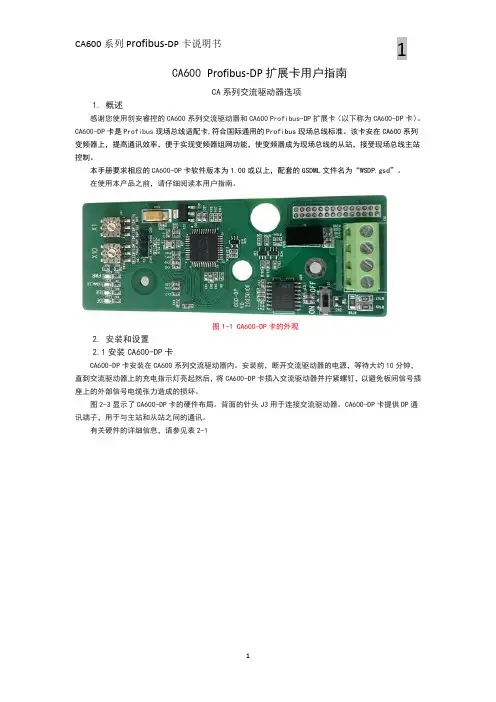
CA600Profibus-DP扩展卡用户指南CA系列交流驱动器选项1.概述感谢您使用创安睿控的CA600系列交流驱动器和CA600Profibus-DP扩展卡(以下称为CA600-DP卡)。
CA600-DP卡是Profibus现场总线适配卡,符合国际通用的Profibus现场总线标准。
该卡安在CA600系列变频器上,提高通讯效率,便于实现变频器组网功能,使变频器成为现场总线的从站,接受现场总线主站控制。
本手册要求相应的CA600-DP卡软件版本为1.00或以上,配套的GSDML文件名为“WSDP.gsd”。
在使用本产品之前,请仔细阅读本用户指南。
图1-1CA600-DP卡的外观2.安装和设置2.1安装CA600-DP卡CA600-DP卡安装在CA600系列交流驱动器内。
安装前,断开交流驱动器的电源,等待大约10分钟,直到交流驱动器上的充电指示灯亮起然后,将CA600-DP卡插入交流驱动器并拧紧螺钉,以避免板间信号插座上的外部信号电缆张力造成的损坏。
图2-3显示了CA600-DP卡的硬件布局。
背面的针头J3用于连接交流驱动器。
CA600-DP卡提供DP通讯端子,用于与主站和从站之间的通讯。
有关硬件的详细信息,请参见表2-1图2-3CA600-DP卡(硬件)表2-1CA600-DP卡的硬件说明符号硬件名称功能描述J3引脚接头用于连接交流驱动器S1Profibus终端电阻110ΩCN1Profibus通信端子SW1,SW2Profibus站号设定DE Profibus-DP通讯指示灯(绿)CA600-DP卡的指示灯说明见表2-2。
ER Profibus-DP故障指示灯(红)COMM_ER变频器通讯指示灯(绿)PWR电源指示灯(绿)表2-2CA600-DP卡的指标说明指示信号状态描述解决方案DE绿色常亮PN正常N/AOFF状态与驱动器通讯断开将P8-11设置为1,并检查交流驱动器是否支持CA600-DP卡。
Profibus协议报文说明
编号:_______________本资料为word版本,可以直接编辑和打印,感谢您的下载Profibus协议报文说明甲方:___________________乙方:___________________日期:___________________1、通信端口参数另外.Profibu««DP的物埋层是采鬼异步串FI遇信,佐输数据格式是以UART 将式进行传输的.每个字符TH1位长,包括一位起始位,一仲数据何.一位偶校骗位和一位停止伸.其中起始仰为。
’悴I上位为L如卜所示.支持的波特率:2、报文格式2 2.J l>rofibus*DP 报文睹式任何亚信仪方要碇佗正常地也据迎5*必须预先设定d 1<文格式,ProHbu^DP 协议中传输报文的格式主要白以卜五种类型:n SI)!;无数据域.用r杏询总线上激活的站点・该报文格式用于上站与从站间的站点查询。
建立好通讯网络后,山站使会向从站发携总线上在线站点的查询,在线的从站收到查询本从站的清求帧,四会回应相应的应答倾n在通信时.主站会时不时地发送杳询帧,确保能与总线上的所有站点进行通信。
2) SD::可变数据域,参数最多,是Profib堆中使用最多的种顿结枸。
3) SD:固定8字节数字域5) SC:用,对上站请求帧的知」叫嗣是由从站发出.SC0x115表2・3 FC功能码说明其中FC劝能码中的第四位(FCB)与第五位(FCV)标志的含义为:FC功能码中的低四位功能码定义为:根据Profibus-DP的通信机制,主站与从站建通信时,预先发送总线查洵帧得知哪地从站处于•总线激活状态,一旦确定总线上的激活站点后,便开始对激活站点进行参数化、组态并诊断,只有当所有配骨正确后才可进入数据交换阶段。
1)诊断报文2)参故化报文3>组态报文OxES4)数据交换报丈数据报文(主站•从站)3、详细的报文含义DC 04 04(主站间的令牌帧,04 04 &示当前的令牌被地址为04的主站持仃)1001 04 49 4E16(主站查询总线上的激活站点,采用轮询的方式,现在查询地址为01的从站)10 02 04 49 4F 16(主站查询总线上的激活站点,采用轮询的方式,现在脊询地址为02的从站)10 04 02 00 06 16(地址为02的从站处。
PROFIBUS转MODBUS-RTU网关使用手册说明书
PROFIBUS转MODBUS-RTU网关PBMD485-K20(主站)PBMD232-K20(主站)使用手册北京微硬创新科技有限公司2009-3目录使用须知 (3)产品系列概述 (3)您关心的技术参数 (3)典型应用网络图 (4)产品功能 (4)1. 硬件连接及STEP7参数配置说明 (5)1.1. 硬件接口及指示灯说明 (5)1.1.1硬件接口说明 (5)1.1.2指示灯说明 (7)1.2. PBMD232/485-K20 STEP7参数配置说明 (7)1.2.1. GSD文件说明 (7)1.2.2. Modbus报文的配置及网关启动操作 (8)1.3. PBMD232/485-K20的通讯状态字及控制字介绍 (9)1.3.1通信状态字 (10)1.3.2通信控制字 (10)2. STEP7硬件建立及配置 (11)2.1. 西门子PLC的PROFIBUS主站配置 (11)2.2. 网关PBMD232/485-K20作为PROFIBUS从站的配置过程 (16)2.2.1. PROFIBUS从站配置——网关做MODBUS主站 (16)3. Modbus-RTU 协议简介 (20)3.1.MODBUS存储区 (20)3.2.MODBUS功能码 (20)3.2.1.读取输出状态(01H) (20)3.2.2.读取输入状态(02H) (21)3.2.3.读取保存寄存器(03H) (21)3.2.4.读取输入寄存器(04H) (22)3.2.5.强制单线圈(05H) (22)3.2.6.预置单保持寄存器(06H) (23)3.2.7.强制多线圈(0FH) (23)3.2.8.预置多寄存器(10H) (23)3.3.MODBUS异常码 (24)附录A:从站状态监测功能说明 (25)附录B:如何使用串口调试助手截取MODBUS报文 (27)附录C:如何使用Modbus Slave连接PBMD232/485-K20(主站) (29)使用须知● 如果您已经熟悉Modbus-RTU协议以及熟练使用西门子配置软件Step7,仅仅关心本产品的使用问题,请参看1.2节《PBMD232/485-K20 STEP7参数配置说明》。
10P-0008 PROFIBUS DP通信卡说明书
10P-0008 PROFIBUS DP Communication CardTo be used with AC10P Series InverterProduct ManualIssue 12016 Parker Hannifin Manufacturing Ltd.All rights strictly reserved. No part of this document may be stored in a retrieval system, or transmitted in any form or by any means to persons not employed by a Parker SSD Drives company without written permission from Parker Automation Wuxi, a division of Parker Hannifin Ltd . Although every effort has been taken to ensure the accuracy of this document it may be necessary, without notice, to make amendments or correct omissions. Parker Automation Wuxi cannot accept responsibility for damage, injury, or expenses resulting therefrom.WARRANTYRefer to Parker Hannifin Manufacturing Limited Terms and Conditions of Sale. These documents are available on request at /ADC . Parker Hannifin Manufacturing Limited reserves theright to change the content and product specification without notice.ContentsI.Overview (1)1.1Introduction (1)1.2 Function (1)II.Specification and appearance (2)2.1 Appearance (2)2.2 Specification (2)2.3 LED display (3)2.4 Terminating resistor (3)III.Installation and connection (4)3.1 Connection between communication card and inverter (4)3.2 Pins definition (5)IV.Profibus-DP communication (6)4.1 Profibus introduction (6)4.2 Communication parameters setting (6)4.3 Profibus communication address setting (7)4.4 PPO type or periodic data format (7)4.4.1 PKW parameter section (8)4.4.2 PZD process data (10)V.GSD file (11)VI.Application (11)6.1 System configuration (12)6.2 New project (12)6.3 Adding PROFIBUS DP bus (14)6.4 Adding GSD file (18)6.5 Parameters configuration (24)6.6 Program example (25)I.Overview1.1IntroductionThe 10P-0008 is compatible with all master stations that support the PROFIBUS protocol. 10P-0008 can be a PROFIBUS-DP slave which can connect Parker’s AC10P series inverter to PROFIBUS network.1.2 Function(1)10P-0008 can read/write inverter parameters by PKW.(2)10P-0008 can interact inverter control data with status data by PZD.(3)With baud rate self-adaption function, the max baud rate is 12Mbps. However the maximum baud rate to the inverter is based on Modbus, which is 57600bps.II.Specification and appearance2.1Appearance(Unit: mm)Fig 2-1Communication card dimension2.2SpecificationFig 2-2 Communication card appearance and structure component2.3 LED display2.4 Terminating resistorTerminating resistors must be fitted to the first and last devices in the system. A "device" may be a drive or PC/PLC.• If the device is at the front of the network it must have terminating resistors. • If the device is at the end of the network it must have terminating resistors. • All other devices in the system should not have terminators.As shown in Fig 2-2, terminating resistors switch is used to select whether to connect terminatingDB15POW DPADDH ADDL ERR COMMDB9 of DP portTerminating resistors switchMounting bracketresistor in the bus. If the two switches are ON, terminating resistor is connected, if the two switches are OFF, terminating resistor is not connected.Fig 2-3 matched terminal resistor diagramNote: If the terminal resistor of the PB Connector is used, please do not use terminal resistor of 10P-0008.III.Installation and connection3.1Connection between communication card and inverterCommunication card is connected to drive by DB15 D type connector.Fig 3-1 connection between communication cardand inverterThere are 3kinds of communication cables.D type DB15 connector pins are as following::3.2 DB9 Pins definitionIV.Profibus-DP communication4.1 Profibus introductionPROFIBUS is a vendor independent, open fieldbus standard for a wide range of applications in manufacturing, process and building automation. Vendor independence and openness are guaranteed by the PROFIBUS standard EN50170. With PROFIBUS, devices from different manufacturers can inter-communicate. Suitable interfaces exist for PLCs, which include the Siemens, Mitsubishi and Allen Bradley range.PROFIBUS-DP (De-central Periphery) is described in DIN 19245 Part 3, and forms part of EN 50170 with P-Net and WorldFIP. However it is important to note that P-Net and WorldFIP are wholly incompatible with PROFIBUS, using different wiring and transmission technologies.The PROFIBUS-DP network uses a high speed version of the RS485 standard, permitting baud rates of up to 12Mbaud.A maximum of 32 PROFIBUS-DP stations (nodes) may be contained within a single networksegment. Use of RS485 repeaters allows a total of up to 126 stations.PROFIBUS-DP is a multimaster, master-slave, token passing network. More detailed information, including a detailed guide to products available, may be obtained from the various world-wide PROFIBUS user organisations.Connection using shielded, twisted-pair cable(EIA RS-485).Either of the two cable types detailed below can be used but we recommend Type A as it allows higher speed and longer cable length.Table 4-1 parameters of transmission cableTable 4-2Maximum line length Per segment4.2 Communication parameters settingPlease set function codes of inverter correctly before using Profibus-DP card. Please refer to the below table:Table 4-34.3 Profibus communication address settingThere are two Hex rotary selectors on the outer shell of communication card (please refer to Fig 4-1), they are used to set the address of Profibus-DP slave, the valid address range is 0x01-0x7D, the decimal range is 1-125, the other address is invalid.ADDHADDLFig 4-1 Address setting selectors4.4 PPO type or periodic data formatThe Profibus DP protocol uses so-called PPOs (Parameter/Process Data Object)in cyclic communication. PPO type data format include two parts, PKW (parameter section) and PZD (process data section).4.4.1 PKW parameter sectionPKW section includes PKE,IND, PWE1 and PWE2, which has in total 4 words. PKW can read and write parameter values.4.4.1.1 PKECommand: request or reply ID.High byte of parameter index: parameter index is 2 bytes. High byte of parameter index corresponds to high byte address of inverter parameters.4.4.1.2 INDLow byte of parameter index: low byte of parameter index corresponds to low byte address of inverter parameters.4.4.1.3 PWEPWE corresponding to parameters values are 2 words, which includes PWE1 and PWE2. When master executes reading command, both PWE1 and PWE2 are 0. When master executes writing command,PWE1 is 0, PWE2 is parameter value. When master operates successfully, PWE1 returns to 0, PWE2 returns to actual parameter values. If master operates failed, PWE1 returns to 0, PWE2 returns to error code.4.4.1.4 Examples of PKWFor example, master reads F111 value. The command value of reading parameter is 1, parameter actual address is 0x010B. If parameter value is 10000=0x2710, and response is failed,Note: please refer to user’s manual of drive for function code.For example, master writes 0x64 to F112. The command value of writing parameter is 2. Parameter actual address is 0x010C. If response is failed, error code 0x01 is returned, it means4.4.2 PZD process dataPZD process data can read and change the inverter parameters periodically in order to control4.4.2.1 PZD1, PZD2The mapping relation between PZD1, PZD2 and inverter is stable, user can not set the mapping relation.(1)When master transmits the data to slave,PZD2 = HSW (frequency setting value, mapping to function code F113, which address is 0x010D)(2)When slave sends data to masterPZD1 = ZSW (status word, mapping to drive running status parameters, which address4.4.2.2 PZD3—PZD10The mapping relation between PZD3—PZD10 and drive parameters is set by master according to GSD configuration information. When master configures slave parameters, master will send mapping address between PZD3-PZD10 and drive parameters. If adapter modulereceives 0x0000 parameter address, it means user does not set parameter address, this PZD will beV.GSD fileGSD file is ASCII-format device description file in a specified form. Each device (master/slave stations) on PROFIBUS has to have its own GSD file.GSD file of 10P-0008 is AC10PROF.gsd.VI.ApplicationThis chapter gives information on configuring the PROFIBUS master station (Simens PLC S7-300) and AC10P inverter for communication through 10P-0008 PROFIBUS DP adapter module.6.1 System configurationFirst system device should be connected correctly, then set the parameters of drive.The parameters setting are as below:F200=3 or 4, F201=3 or 4, F203=10, F900=1, F901=2, F903=0, F904=6.6.2 New projectOpen “SIMA TIC Manager”, the page is as below:Fig 6-1Select File-> New Project Wizard, and click “Next”, as shown in Fig 6-2Fig 6-2Select CPU model according to PLC S7-300. We take the example of CPU315-2PN/DPin here. Click “Next”, as it is shown in Fig 6-3.Fig 6-3Select blocks and blocks language. Normally OB1 and LAD language are default value, as it is shown in Fig6-4.Then click “Next”,Fig 6-4Input project name, and click “Finish”, as it is shown inFig6-5Fig 6-5 The new page is shown in Fig6-6Fig 6-66.3 Adding PROFIBUS DP busSelect “SIMA TIC 300 Station”, and as it is shown in Fig6-7Fig 6-7Double click “Hardware”, Hardware configuration page is shown in Fig6-8.Fig 6-8Double click “MPI/DP, and next Fig is shown, to select interface type “PROFIBUS”.Fig6-9Click “Properties” in Fig 6-9, below fig is shown. The address of DPmaster can be changed.Fig6-10Click “New” in Fig 6-10, below fig is shown. Set baud rate of DP bus, and click“OK”.Fig6-11In the below figure, PROFIBUS 1.5Mbps is DP bus, and click “OK”.Fig6-12Below figure is shown, and click “OK”Fig6-13A bus is shown in configuration figure, as shown in Fig6-14Fig6-146.4 Adding GSD fileSelect “Options”-> “Install GSD File”, as shown in Fig6-15.Fig 6-15 Find out and select GSD file, and click “Install”.Fig6-16 GSD file installation was completed successfully.Fig6-17After finishing installing GSD file, below Fig is shown. DP module is shown in the right blank. Select bus and double click “10P-0008”, to add DPslave.Fig6-18After adding slave, slave of 10P-0008 is shown in DP bus.Fig6-19Double click DPslave module, and click “PROFIBUS” to show new page.Fig6-20Set address of DP slave in the blow page, it should be same with address of 10P-0008. Then click “OK”.Fig6-21Select slot 1, and double click “PPO1:4PKW,2PZD” in the right blank of blow f ig.Fig6-22The parameters of “4PKW 2PZD” are configured to slot 1 and slot 2.Fig6-23After configuring parameters, click the button in the HW Config window.Fig6-256.5 Parameters configurationDouble click “10P-0008” in the fig6-23, fig6-26 is shown. The mapping relation between PZD1, PZD2 and drive parameters is stable, user is forbidden to setting it. User can set the mapping relation between PZD3-PZD10 and drive parameters in the “Device-Specific parameters”. User can set the mapping relation according to actual requirement. The default setting is 0x0000 if user does not set the mapping relation. System does not have operation for the setting value 0x0000. “out” in “PZD out” is aimed at DP master, which corre sponds to output area of DP master. “in” in “PZD in” is aimed at DP master, which corresponds to input area of DP master. In our example, 4PKW+2PZD is selected, and the parameters of PZD1 and PZD2 need not to be set.Fig6-266.6 Program exampleSFC14,SFC15 command instructionSFC14: continuous data of reading DPslaveFig6-27LADDR means the slave initial address in input area of master, W#16#100 means IW256.RET_V AL means error code.RECORD means initial address of reading data in DP slave.SFC15: continuous data of writing DPslaveFig6-28LADDR means initial address of slave in output area of master. W#16#100 means QW256. RECORD means initial address of writing data in DP slave.RET_V AL means error code.Run the program in the Fig6-29. The input/output data corresponding to PKW will be updated. It can realize to read/write drive parameters by PKW.Fig6-29Run the program shown in Fig6-30. The input/output data corresponding to PZD1 and PZD2 will be updated. And the data of drive parameters corresponding to PZD can be updated.Fig6-30。
安川变频器Profibus 通讯手册 SI-P
6. Plug the 2CN connector of Profibus-DP Control Card SI-P into the 2CN connector (60 pins) on the control board of the inverter. Gently push the SI-P card until the stand-off posts engage the two holes on the option card. Secure the SI-P card (See part of the side view).
Page 2
VS-616G5 Option Instruction Manual: Profibus-DP Control Card SI-P
INTRODUCTION
The Profibus-DP Control Card SI-P is used to connect the VS-616G5 inverter to a Profibus-DP network. The option card supports 32 bytes of input data, 32 bytes of output data, data transmission rates of up to 12 Mbps, and uses a RS-485 electrical interface.
VS-616G5
Option Instruction Manual
Profibus-DP Control Card SI-P
! WARNING